K e e l i n g C o m p a n y
|
|
|
- Cory Elliott
- 5 years ago
- Views:
Transcription


1 e e l i n g C o m p a n y GOLF IRRIGATION WIRE Page 87


2 GOLF IRRIGATION WIRE e e l i n g C o m p a n y Page 88
3 e e l i n g C o m p a n y It is the responsibility of the installer to connect all electronic irrigaon equipment for which he is responsible to earth ground in accordance with Arcle 250 of the Naonal Electrical Code ( NEC.) Use grounding electrodes that are UL listed or manufactured tomeet the minimum requirements of Arcle 250 of the 2005 edion of the NEC. At the very minimum, the grounding circuit will include a copper clad steel ground rod, a solid copper ground plate and 100 pounds of PowerSet earth contact material, as defined below and per the following detail. This detail is the minimum requirement for supplementary grounding of any electronic equipment. Other details, for a multude of field situaons, are available form the American Society of Irrigaon Consultants, ASIC Guideline ( Design Guides.) GOLF IRRIGATION WIRE Page


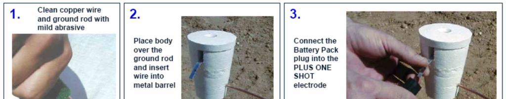
 shall be connected to the ground rod by the installer using a Cadweld GR1161GPLUS One-Shot welding kit [Paige Electric part number 1820037P.")
4 GOLF IRRIGATION WIRE e e l i n g C o m p a n y The ground grid components must be installed with the dimensional relaonships shown in the detail above. WIRES, CABLES, AND ELECTRONIC EQUIPMENT MUST BE INSTALLED OUT- SIDE THE SPHERE OF INFLUENCE OF THE GROUNDING ELECTRODES. Ground rods are to have a minimum diameter of 5/8 and a minimum length of 10 feet. These are to be driven into the ground in a vercal posion or an oblique angle not to exceed 45 degrees at a locaon 10 feet from the electronic equipment. The rod is to be stamped with the UL logo [Paige Electric part number ] A 6 AWG solid bare copper wire (about 12 feet long) shall be connected to the ground rod by the installer using a Cadweld GR1161GPLUS One-Shot welding kit [Paige Electric part number P.] This wire shall be connected to the electronic equipment ground lug. The copper grounding plate assemblies shall be 4 x 96 x [Paige Electric part number L.] A 25 -foot connuous length (no splices allowed unless us- ing exothermic welding process) of 6 AWG solid bare copper wire is to be a ached to the plate by the manufacturer using an approved welding process. This wire is to be connected to the electronic equipment ground lug. If the equipment ground lug only accepts one wire, connect the second wire to the first with a brass split bolt, as close to the equipment lug as possible. The ground plate is to be installed to a minimum depth of 30, or below the frost line if it is lower than 30, at a locaon 8 feet from the electronic equipment and underground Page 90 CONTINUES ON NEXT PAGE


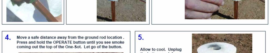
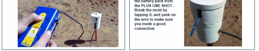
5 wires and cables. e e l i n g C o m p a n y Two 50-pound bags of PowerSet [Paige Electric part number ] earth contact material must be spread so that it surrounds the copper plate evenly along its length within a 6 wide trench. Salts, ferlizers, bentonite clay, cement, coke, carbon, and other chemicals are not to be used to improve soil conducvity because these materials are corrosive and will cause the copper electrodes to erode and become less effecve with me. Install all grounding circuit components in straight lines. When necessary to make bends, make sweeping turns, as shown. When connecng bare copper wire to the ground lug of electronic equipment, it must be fed through a dedicated 1.5 plasc sweep ell. The earth-to-ground resistance of this circuit is to be measured using a Megger, or other similar instrument, and the reading is to be no more than 10 ohms. If the resistance is more than 10 ohms, addional ground plates and PowerSet are to be installed using ASIC Guidelines GOLF IRRIGATION WIRE ( www. asic. org, Design Guides.) It is required that the soil surrounding copper electrodes within the sphere of influence be kept at a minimum moisture level of 15% (by volume) at all mes. All underg round circuit connecons are to be made using an exothermic welding process by ulizing products such as the Cadweld PLUS One-Shot kits. Solder shall not be allowed to make connecons. In order to e n s u re proper ignion of the One-Shot, the Cadweld PLUS C o n t rol Unit igniter must be ulized [ Paige Electric part number CU.] The 6 AWG bare copper wires are to be installed in as straight a line as possible, and if it is necessary to make a turn or a bend it shall be done in a sweeping curve with a minimum radius of 8 and a minimum included angle of 90. Mechanical clamps shall be permi ed temporarily during the resistance test process, but are to be replaced with Cadweld PLUS One-Shot kits immediately thereaer. ALL GROUNDING COMPONENTS MUST BE CONNECTED TO THE EQUIPMENT BEFORE ANY OTHER CONNECTION IS MADE. Page 91
6 GOLF IRRIGATION WIRE e e l i n g C o m p a n y Page 92


7 e e l i n g C o m p a n y GOLF IRRIGATION WIRE Page 93


8 GOLF IRRIGATION WIRE e e l i n g C o m p a n y Page 94
courtesy of Hunter Industries Inc. courtesy of Rain Bird C o r p o r a t i o n courtesy of Hunter Industries Inc. The wiring guide
 courtesy of Hunter Industries Inc. courtesy of Rain Bird C o r p o r a t i o n courtesy of Hunter Industries Inc. The wiring guide W h y? Because you need an irrigation wire and cable pro. Who understands
2/15/2015. Current will always try to return to its source. In order for there to be current, there must be a complete circuit
 Current will always try to return to its source In order for there to be current, there must be a complete circuit Current will take as many paths or circuits available to it to return to the source The
SDCS-03 DISTRIBUTION NETWORK GROUNDING CONSTRUCTION STANDARD GROUNDING RESISTANCE MEASUREMENTS AND IMPROVEMENT
 SEC DISTRIBUTION GROUNDING STANDARD SDCS-03 DISTRIBUTION NETWORK GROUNDING CONSTRUCTION STANDARD (PART-III) REV-01 GROUNDING RESISTANCE MEASUREMENTS AND IMPROVEMENT This specification is property of SEC
CONTINUING EDUC ATION
 3 CONTINUING EDUC ATION FOR WISCONSIN ELECTRICIANS 2017 NEC Article 250 2 Hours WISCONSIN CONTRACTORS INSTITUTE N16 W23217 Stone Ridge Drive Suite 290 Waukesha, WI 53188 262-409-4282 www.wcitraining.com
This Manual Part recommends design criteria for resistors suitable for railway signaling circuits other than electronic.
 2016 Part 14.2.15 Recommended Design Criteria for Resistors Revised 2016 (6 Pages) A. Purpose z00381hn 3/12/15 8:34 AM z00381hn 3/12/15 8:37 AM This Manual Part recommends design criteria for resistors
COMMERCIAL ITEM DESCRIPTION RODS, GROUND (WITH ATTACHMENTS)
") INCH-POUND 30 May 2002 SUPERSEDING A-A-55804 11 March 1996 COMMERCIAL ITEM DESCRIPTION RODS, GROUND (WITH ATTACHMENTS) The General Services Administration has authorized the use of this commercial item
INCH-POUND 30 May 2002 SUPERSEDING A-A-55804 11 March 1996 COMMERCIAL ITEM DESCRIPTION RODS, GROUND (WITH ATTACHMENTS) The General Services Administration has authorized the use of this commercial item
Wire Mesh Cable Tray System for Channeling of Cable Wiring
 Wall Mount A Simple-to-Install basket for safe and proper installation of facility wiring in the ceiling and under the floor. Floor Mount Wire Mesh Cable Tray System for Channeling of Cable Wiring Features
SDCS-03 DISTRIBUTION NETWORK GROUNDING CONSTRUCTION STANDARD (PART-I) UNDERGROUND NETWORK GROUNDING. Rev. 01
 UNDERGROUND NETWORK GROUNDING. Rev. 01") SDCS-03 DISTRIBUTION NETWORK GROUNDING CONSTRUCTION STANDARD (PART-I) UNDERGROUND NETWORK GROUNDING Rev. 01 This specification is property of SEC and subject to change or modification without any notice
SDCS-03 DISTRIBUTION NETWORK GROUNDING CONSTRUCTION STANDARD (PART-I) UNDERGROUND NETWORK GROUNDING Rev. 01 This specification is property of SEC and subject to change or modification without any notice
RADIO AND TELEVISION SATELLITE EQUIPMENT
 ARTICLE 810 RADIO AND TELEVISION SATELLITE EQUIPMENT Introduction to Article 810 Radio and Television Satellite Equipment This article covers transmitter and receiver (antenna) equipment and the wiring
Foundation Specifications
 Installation Instructions Bulletin 237746 Foundation Specifications for High-Wind 4.5-Meter Earth Station Antennas Revision C 1.0 INTRODUCTION 1.1 This document specifies typical foundation characteristics,
Lightning Protection Equipment
 LINE CARD Grounding Exothermic Lightning Protection Lightning Protection Equipment Manufacturing Engineering Services Training Typical Roof Lightning Protection Layout MOUNTED VERTICALLY (WITH FASTENERS
Factory Assistance: Phone: Fax: Page 1
 CABLE RUNWAY ACCESSORIES Radius Drop / Stringer Drop Provides 3 bend radius Radius drop fits 6, 12 and 18 runway made from 1-1/2 x 3/8 tubing Steel construction Includes (3) cable spools, (1) bolt, (1)
CHAPTER 15 GROUNDING REQUIREMENTS FOR ELECTRICAL EQUIPMENT
 CHAPTER 15 GROUNDING REQUIREMENTS FOR ELECTRICAL EQUIPMENT A. General In a hazardous location grounding of an electrical power system and bonding of enclosures of circuits and electrical equipment in the
AC Decoder Installation Instructions PC-Driven Models
 AC Decoder Installation Instructions PC-Driven Models Specification PC-Driven Models can control up to 250 Decoder Modules per Gateway Input Power Supply: 100 240 VAC, 50/60 Hz Gateway Input Current: 1.6A/1.0A
Attendee Announcements
 Attendee Announcements Seminar Raffle Be sure to drop your raffle ticket in the drum at today s Keynote located in the Mile High Ballroom. You have a chance to win a $250 American Express Gift Card. One
EPG. by Chris C. Kleronomos
 April 1994 EFFECTIVE EQUIPMENT GROUNDING ECOS Electronics Corporation by Chris C. Kleronomos The quality of the electrical wiring and grounding in a facility containing sensitive electronic equipment is
VPN: ISBXLR. Copyright Black Box Corporation. All rights reserved Park Drive Lawrence, PA Fax
 VPN: ISBXLR Copyright 2003. Black Box Corporation. All rights reserved. 1000 Park Drive Lawrence, PA 15055-1018 724-746-5500 Fax 724-746-0746 JULY 2003 RM649-R2 RM657 RM664 RM861 RM650 RM658-R2 RM665-R2
Status Date Prepared Reviewed Endorsed Approved
 Discipline Engineering Standard NSW Category Electrical Title Reference Number PDS 05 (RIC Standard: EP 12 10 00 11 SP) Document Control Status Date Prepared Reviewed Endorsed Approved Mar 05 Standards
SECTION WIREWAYS FOR RADIOLOGY EQUIPMENT
 PART 1 - GENERAL 1.1 DESCRIPTION SECTION 26 05 36 WIREWAYS FOR RADIOLOGY EQUIPMENT SPEC WRITER NOTE: Delete between //----// if not applicable to project. Also, delete any other item or paragraph not applicable
IC System TM Design Guide v 2.3
 IC System TM Design Guide v 2.3 Updated August 2016 IC System TM Product Definitions... 3 Integrated Control Interface (ICI)... 4 Integrated Control Module (ICM)... 5 Integrated Control Surge Device (ICSD)...
Ground Clamps Cable Tray
 commercial and industrial fittings: ing Fittings and Solderless Connectors Clamps Cable Tray Terminates ground wire to cable tray. For aluminum or copper conductors. 1 4 hex wrench tightens both tray and
Wire Mesh Cable Tray System for Channeling of Cable Wiring
 Wire Mesh Cable Tray System for Channeling of Cable Wiring A Simple-to-Install basket for safe and proper installation of facility wiring in the ceiling and under the floor. Wall Mount Ceiling Mount s
Outline. Grounding Washer, Electrical Equipment Bond (WEEB) Acme Cable Clips Acme Conduit Entry (ACE) Questions
 Acme Cable Clips Acme Conduit Entry (ACE) Questions") www.we-llc.com Outline Grounding Washer, Electrical Equipment Bond (WEEB) Acme Cable Clips Acme Conduit Entry (ACE) Questions Bonding & Grounding Grounding Terms Equipment Grounding: The National Electrical
www.we-llc.com Outline Grounding Washer, Electrical Equipment Bond (WEEB) Acme Cable Clips Acme Conduit Entry (ACE) Questions Bonding & Grounding Grounding Terms Equipment Grounding: The National Electrical
American Electrical Institute
 American Electrical Institute Oregon Electricians Continuing Education Grounding & Bonding (Article 250) 4 Hours American Electrical Institute PO Box 31131 Spokane, WA 99223 www.aeitraining.com Article
Article 250 Grounding & Bonding
 Article 250 Grounding & Bonding AMERICAN ELECTRICAL INSTITUTE N16 W23217 Stone Ridge Dr. Waukesha, WI 53188 855-780-5046 www.aeitraining.com DISCLAIMER NOTE: This course is APPROVED for continuing education
Toro OSMAC RDR Field Satellite Electric Actuation Models Installation Instructions
 Toro OSMAC RDR Field Satellite Electric Actuation Models Installation Instructions Introduction The OSMAC RDR Satellite Controller is designed for installation on a substantial concrete foundation with
UFGS (November 2008) UNIFIED FACILITIES GUIDE SPECIFICATIONS
 UNIFIED FACILITIES GUIDE SPECIFICATIONS") USACE / NAVFAC / AFCESA / NASA UFGS-27 05 28.36 40 (August 2011) ----------------------------------- Preparing Activity: NASA Superseding UFGS-27 05 28.36 40 (November 2008) UNIFIED FACILITIES GUIDE SPECIFICATIONS
USACE / NAVFAC / AFCESA / NASA UFGS-27 05 28.36 40 (August 2011) ----------------------------------- Preparing Activity: NASA Superseding UFGS-27 05 28.36 40 (November 2008) UNIFIED FACILITIES GUIDE SPECIFICATIONS
Asset Protection Cathodic Protection Soil Resistivity Measurement. Work Instruction No.:
 Asset Protection Cathodic Protection Soil Resistivity Measurement Approved by: Manager Pipeline Standards 1 PURPOSE This work instruction describes the processes to be followed when measuring soil resistivity.
Wisconsin Contractors Institute Continuing Education
 IMPORTANT NOTE: You should have received an email from us with a link and password to take your final exam online. Please check your email for this link. Be sure to check your spam folder as well. If you
Installing a COMROD AS1R Whip Antenna with Anchor Post
 Installing a COMROD AS1R Whip Antenna with Anchor Post IS10012 Issue 1.0...15 September 2010 Nautel Limited 10089 Peggy's Cove Road, Hackett's Cove, NS, Canada B3Z 3J4 T.877 6 nautel (628835) or +1.902.823.2233
BUILD A HIGH PERFORMANCE TWO ELEMENT TRI-BAND CUBICAL QUAD. By Bob Rosier K4OCE INTRODUCTION THEORY AND GENERAL INFORMATION
 BUILD A HIGH PERFORMANCE TWO ELEMENT TRI-BAND CUBICAL QUAD INTRODUCTION By Bob Rosier K4OCE Lots of DX can be worked with a dipole at the QRP level, however, a beam will obviously give you additional gain
UNIFIED FACILITIES GUIDE SPECIFICATIONS
 USACE / NAVFAC / AFCEC / NASA UFGS-27 05 28.36 40 (May 2017) --------------------------------- Preparing Activity: NASA Superseding UFGS-27 05 28.36 40 (August 2014) UNIFIED FACILITIES GUIDE SPECIFICATIONS
kv AC substation
 132-400 kv AC substation Outdoor AC substations Earthing systems ETS-50-08-01, Rev. 0 technical standard Document no. 13/90592-127 ETS-50-08-01 v. 0 REVISION VIEW Document no.: 13/90592-127 Version Author
Lightning Strikes. Presented to the Greater Norwalk Amateur Radio Corporation Inc. February 8, 2017 Steven M. Simons W1SMS
 Lightning Strikes Presented to the Greater Norwalk Amateur Radio Corporation Inc. February 8, 2017 Steven M. Simons W1SMS ARRL CT State Technical Coordinator The Power of Lightning What is a Ground? Design
SPECIAL SPECIFICATION LIGHTNING PROTECTION SYSTEM
 2004 Specifications CSJ 3622-01-001, ETC. SPECIAL SPECIFICATION 8398 LIGHTNING PROTECTION SYSTEM 1. Description. This Special Specification governs the design and installation of Lightning Protection System
TD1016: An overview of Lightning Protection for Ham Radio Stations.
 TD1016: An overview of Lightning Protection for Ham Radio Stations. PolyPhaser 2225 Park Place Minden, NV 89423, USA TF: 800.325.7170 T: +1.775.782.2511 F: +1.775.782.2551 www.polyphaser.com TD1016: An
NORMATIVE REFERENCES
 American National Standards Institute NORMATIVE REFERENCES ANSI C135.30 1988 (expired 1993) Zinc-Coated Ferrous Ground Rod Electrodes for Overhead or Underground Lines American Society for Testing and
SAFETY AND HEALTH STANDARD ELECTRICAL GROUNDING Effective Date: 07/17/10 Standard: Document Number: KUCSH0039 Rev: 4
 SAFETY AND HEALTH STANDARD ELECTRICAL GROUNDING Effective Date: 07/17/10 Standard: 16.10 Document Number: KUCSH0039 Rev: 4 16.10.1 INTRODUCTION 16.10.1.1 The intent of this standard is to ensure that continuity
GROUNDING. What is it? Al Lewey K7ABL. Disclaimer
 GROUNDING What is it? Al Lewey K7ABL Disclaimer Disclamier Mechanical Engineer with some electrical background My primary reference is References UP THE TOWER The Complete Guide to Tower Construction By
NORMATIVE REFERENCES
 American National Standards Institute NORMATIVE REFERENCES ANSI C135.30 1988 (expired 1993) Zinc-Coated Ferrous Ground Rod Electrodes for Overhead or Underground Lines American Society for Testing and
LBI-39067B Standard for Site Grounding and Protection
 Standard for Site Grounding and Protection ericssonz Table of Contents Page 1. OBJECTIVE... 3 1.1. GROUND THEORY... 3 1.2. SCOPE... 3 1.3. GENERAL... 4 1.4. RESPONSIBILITY... 4 1.4.1. Minimum Requirements...
CONTINUOUS COUNTERPOISE ON POLES
 Project Procedure CONTINUOUS COUNTERPOISE ON POLES 07/25/2011 PAGE 1 OF 5 1.0 PURPOSE The purpose of this procedure is to provide guidance and direction for the installation of continuous counterpoise
14 AWG 2 AWG: 600 Volt
 INDUSTRIAL AUTOMATION & PROCESS CONTROL CABLES 18.70 600V Type MC Metal Clad and Teck-Style Cables Overview Metal Clad Interlocked PVC Outer Jacket Teck-Style PVC Outer Jacket Introduction Polyester Wrap
Grounding and Lightning arrestors
 CHAPTER - Four Grounding and Lightning arrestors 4.1. Introduction Electrical connection of neutral point of a supply system or the non current carrying part of electrical equipments to the general mass
High Voltage Pylon Earth Measurements
 High Voltage Pylon Earth Measurements Speaker: Gavin van Rooy Authors: Frank Barnes and Gavin van Rooy Tycom (Pty) Ltd PO Box 3546, Randburg, 2125, South Africa E-mail: frank@tycom.co.za Phone: 011 787
White Paper Security Cameras, CATV, GPS and Satellite Protection
 White Paper Security Cameras, CATV, GPS and Satellite Protection 1485-042 White Paper Security Cameras, CATV, GPS and Satellite Protection Security Cameras, CATV, GPS & Satellite Protection Outdoor Closed
UNDERSTANDING. Ground Resistance Testing. I Voltmeter (E) Grounding. electrode. under test. Ground rod and clamp
 Grounding. electrode. under test. Ground rod and clamp") UNDERSTANDING Ground Resistance Testing Current supply E Ammeter (I) I Voltmeter (E) Grounding electrode under test X Auxiliary potential electrode Y Auxiliary current electrode Z R Rx R1 R2 Rn-1 Rn EARTH
UNDERSTANDING Ground Resistance Testing Current supply E Ammeter (I) I Voltmeter (E) Grounding electrode under test X Auxiliary potential electrode Y Auxiliary current electrode Z R Rx R1 R2 Rn-1 Rn EARTH
CORFLEX VFD CORFLEX VFD Part Number: Drive Cable
 Part Number: Drive Cable Armored Variable Frequency Drive Cable UL Type MC HL, 600V, 90 C rated - LEAD FREE Description 3 conductor with 3 ground wires, continuous corrugated and welded, impervious aluminum
I dedicate this book to the Lord Jesus Christ, my mentor and teacher. Proverbs 16:3 NOTICE TO THE READER ABOUT THE AUTHOR
 April 28, 2018 NOTICE TO THE READER The publisher does not warrant or guarantee any of the products described herein or perform any independent analysis in connection with any of the product information
HV Substation Earthing Design for Mines
 International Journal of Engineering Research and Development e-issn: 2278-067X, p-issn: 2278-800X, www.ijerd.com Volume 4, Issue 6 (October 2012), PP. 100-107 HV Substation Earthing Design for Mines M.
99 Straight Sections 100 fittings, splices & connectors. 103 fasteners
 99 Straight Sections 100 fittings, splices & connectors 102 accessories 103 Cable unway is available in two styles, tubular side rails that are lightweight yet strong and solid-bar side rails that offer
Foundation Specifications for 5.6-Meter Modular Earth Station Antennas
 Installation Instructions Bulletin 237029 Foundation Specifications for 5.6-Meter Modular Earth Station Antennas Revision A Introduction This document specifies typical foundation characteristics, designs,
SDCS-03 DISTRIBUTION NETWORK GROUNDING CONSTRUCTION STANDARD (PART-II) OVERHEAD NETWORK GROUNDING. Rev. 01
 OVERHEAD NETWORK GROUNDING. Rev. 01") SEC DISTRIBUTION GROUNDING STANDARD SDCS-03 Part-II Rev.01 SDCS-03 DISTRIBUTION NETWORK GROUNDING CONSTRUCTION STANDARD (PART-II) OVERHEAD NETWORK GROUNDING Rev. 01 This specification is property of SEC
SEC DISTRIBUTION GROUNDING STANDARD SDCS-03 Part-II Rev.01 SDCS-03 DISTRIBUTION NETWORK GROUNDING CONSTRUCTION STANDARD (PART-II) OVERHEAD NETWORK GROUNDING Rev. 01 This specification is property of SEC
Need for grounding Codes and Standards for grounding Wind Turbine Generator grounding design Foundation + Horizontal Electrode grounding design
 IEEE PES Transmission and Distribution Conference 2008 Panel Session Large Wind Plant Collector Design Wind Farm Collector System Grounding by Steven W. Saylors, P.E. Chief Electrical Engineer Vestas Americas
SECTION TRACER WIRE FOR NONMETALLIC PIPE
 PART 1 GENERAL 1.1 DESCRIPTION A. The CONTRACTOR shall furnish and install a conductive tracer wire with all buried plastic water mains, services and appurtenances in accordance with the Water Utilities
Outdoor Installation 2: Lightning Protection and Grounding
 Outdoor Installation 2: Lightning Protection and Grounding Training materials for wireless trainers This one hour talk covers lightning protection, grounding techniques and problems, and electrolytic incompatibility.
Foundation Specifications for 7.6-Meter Modular Earth Station Antennas
 Installation Instructions Foundation Specifications for 7.6-Meter Modular Earth Station Antennas Bulletin 237186A Revision A Introduction This document specifies typical foundation characteristics, designs,
ENGINEERING REPORT PHASES I & II MITIGATOR PERFORMANCE TESTS
 ENGINEERING REPORT PHASES I & II MITIGATOR PERFORMANCE TESTS INDUCED AC MITIGATION PERFORMANCE ON A STEEL GAS TRANSMISSION PIPELINE REPORT OF JANUARY 29, 2014 Copyright MATCOR, Inc. 2014 MITIGATOR TM VS.
WIRE MESH CABLE TRAY
 2014 WIRE MESH CABLE TRAY INSTALLATION GUIDE (CABLE BASKET) WIRE MESH CABLE TRAY (CABLE BASKET) PRODUCT INFORMATION - MAIN UNIT TECHNICAL PARAMETERS Materials Surface Finishing Thickness of coating Application
UNDERSTANDING. Ground Resistance Testing. Soil Resistivity. Ground Resistance. 3-Point Measurements. 4-Point Measurements. Clamp-On Measurements
 UNDERSTANDING Ground Resistance Testing Current supply E Ammeter (I) I Voltmeter (E) Ground electrode under test X Auxiliary potential electrode Y Auxiliary current electrode Z R Rx R1 R2 Rn-1 Rn EARTH
High Voltage Pylon earth Measurements. Tycom (Pty) Ltd Frank Barnes Comtest (Pty) Ltd Presented by Gavin van Rooy
 Ltd Frank Barnes Comtest (Pty) Ltd Presented by Gavin van Rooy") High Voltage Pylon earth Measurements Tycom (Pty) Ltd Frank Barnes Comtest (Pty) Ltd Presented by Gavin van Rooy Abstract The earth connection of high voltage electrical power line pylons is obviously
High Voltage Pylon earth Measurements Tycom (Pty) Ltd Frank Barnes Comtest (Pty) Ltd Presented by Gavin van Rooy Abstract The earth connection of high voltage electrical power line pylons is obviously
WaveTrax. Fiber Cable Management System
 Table of Contents 1. Overview... 3 2. Ordering Information... 8 Fiber Trough System... 8 Express T (Expand Trough Runs without Cutting)... 18 Mounting Brackets... 20 Vertical Fiber Management Solutions...
CA - CONTROLLER ASSEMBLY
 Controller Assemblies for online configuration. CA - CONTROLLER ASSEMBLY RB1 Rain Bird ESP-MC 12, 24 stations Rain Bird ESP-LXMEF 8, 12, 16, 20, 24, 28, 32, 36, 40, 44, 48 stations Rain Bird ESP-LXMD 50,
Zann Jones
 Zann Jones www.zannjones.com All graphics, photos, and content were created by Zann Jones. They are here to be enjoyed, but unauthorized duplication beyond personal use is prohibited. All information presented
Industrial and Commercial Power Systems Topic 7 EARTHING
 The University of New South Wales School of Electrical Engineering and Telecommunications Industrial and Commercial Power Systems Topic 7 EARTHING 1 INTRODUCTION Advantages of earthing (grounding): Limitation
From dc to 10 GHz the. VSWR shall not exceed 1.3 &.04 (f) where f is the frequency in Gigahertz (GHz).
 where f is the frequency in Gigahertz (GHz).") 121 Series Coaxial Snap On & Screw On Types / 50 Ohm & 75 Ohm These 50 and 75 Ohm coaxial connectors are easily inserted into your printed circuit board using an insertion tool. Solder is eliminated and
121 Series Coaxial Snap On & Screw On Types / 50 Ohm & 75 Ohm These 50 and 75 Ohm coaxial connectors are easily inserted into your printed circuit board using an insertion tool. Solder is eliminated and
6M HALO VERSON II + OPTIONAL 2M GROUND PLANE
 The halo is an omnidirectional, horizontally polarized antenna with about the same gain as a dipole but without the low elevation nulls off the ends (+5.5 to +3.5dBi variation for the Halo vs. +7.9 to
Agenda. Earthing of Telecom Installations using Single Point Earthing. Reference Documents. How many earths? Earthing Issue...
 Earthing of Telecom Installations using Single Point Earthing R. Saji Kumar DGM (IT) O/o The Chief General Manager Trivandrum Agenda Reference Documents Earthing Issue & the Problems Earthing Principle
National Radio Astronomy Observatory Socorro, NM EVLA Memorandum 41 Lightning Protection for Fiber Optic Cable. T. Baldwin June 05, 2002
 National Radio Astronomy Observatory Socorro, NM 87801 EVLA Memorandum 41 Lightning Protection for Fiber Optic Cable T. Baldwin June 05, 2002 Summary Double-armor triple-sheath fiber optic cable will be
60Hz Ratings. Typical Applications. Features & Characteristics. Ratings
 The PCR is a solid-state device designed to simultaneously provide DC isolation and AC continuity/grounding when used with cathodically protected structures, such as pipelines, tanks, grounding systems,
Product Specification provides test and performance results for insulated terminals and splices for Class 1 E Nuclear applications.
 This specification covers the requirements for application of PIDG terminals, splices, and end caps in various operating environments. Each consists of a precision formed metal wire barrel and a copper
Model Color Wire Combination Range Wire Combination Range (mm) Quantity Cat. No. Box of V. Carton of 1, Gray.
 Quantity Cat. No. Box of V. Carton of 1, Gray.") Wire-Nut Wire Connectors Yellow and red Wire-Nut Wire Connectors can easily be applied using the Twist-a-Nut Screwdriver. Five color-coded models cover wire sizes from 22 to 6 AWG Fixed, square-wire spring
Wire-Nut Wire Connectors Yellow and red Wire-Nut Wire Connectors can easily be applied using the Twist-a-Nut Screwdriver. Five color-coded models cover wire sizes from 22 to 6 AWG Fixed, square-wire spring
Customer Requirements RF Antenna Installations
 Application Terms Attachment requirements and clearances on the Pole for Radio Frequency (RF) antenna equipment installations. This standard is intended to allow electrical workers to perform their normal
CABLE TRAYS & STRUTS CATALOUGE
 CABLE TRAYS & STRUTS CATALOUGE We are the Manufacturer for Copper Bonded Ground Rod and Contract Manufacturing Company for other products made from Brass, Copper, Gunmetal, Bronze, Cast Iron, Malleable
Harger Lightning & Grounding. *Grounding and Bonding* The Foundation For Effective Electrical Protection
 Harger Lightning & Grounding *Grounding and Bonding* The Foundation For Effective Electrical Protection Objectives 1. Define the difference between grounding & bonding and to describe the roles they play
IMMS-CI-HW. Communications Controller Interface. Installation Instructions IMMS. Controller. Interface. AC From Transformer 24 VAC REM 24 VAC SEN
 CI 4 Comm. IMMS-CI-HW Communications Interface POWER From Transformer Ground To REM Installation Instructions To SmartPort Sensor 1 Sensor 2 Sensor 3 From Sensors Sensor Common IMMS Interface From SI or
S INGLE CIRCU I T 120V. LABELING: cul listed. GES Track Components. Flex Connector GES 23 GES 17. Dead Ends GES 41. (use with any connector)
") S INGLE CIRCU I T 120V G E S 1 CIR 120V Power supply for ElectraLED track lighting fixtures Architectural grade, extruded aluminum housing Milled grounding bar provides continuous ground contact Continuously
S INGLE CIRCU I T 120V G E S 1 CIR 120V Power supply for ElectraLED track lighting fixtures Architectural grade, extruded aluminum housing Milled grounding bar provides continuous ground contact Continuously
Stray Voltage and Swimming Pools
 Stray Voltage and Swimming Pools Marty L. Page, P.E. Southern Company malpage@southernco.com October 19 th 2009 2009 Jodie Lane National Conference for Stray Voltage Detection, Mitigation & Prevention
1. TRACER WIRE. I. Application. Material Specification. Page 1 of 16
 Page 1 of 16 1. TRACER WIRE I. Application A Tracer Wire must be installed on all non-metallic watermains and sanitary force mains. The wire shall be installed in such a manner as to be able to properly
SECTION UNDERGROUND POWER DUCT AND SUB-STRUCTURES. A. Section : Trenching, Backfilling, and Compacting
 SECTION 33 71 19 UNDERGROUND POWER DUCT AND SUB-STRUCTURES PART 1 GENERAL 1.1 RELATED WORK A. Section 31 23 33: Trenching, Backfilling, and Compacting B. Section 32 01 00: Site Restoration and Rehabilitation
Collection of standards in electronic format (PDF) 1. Copyright
 1. Copyright") Collection of standards in electronic format (PDF) 1. Copyright This standard is available to staff members of companies that have subscribed to the complete collection of SANS standards in accordance
Collection of standards in electronic format (PDF) 1. Copyright This standard is available to staff members of companies that have subscribed to the complete collection of SANS standards in accordance
TRANSMITTAL LETTER. As Builts Change Order Contract Copy of Letter Insurance. For approval Approved as submitted Resubmit copies for approval
 Redwood City Electric, Inc. TRANSMITTAL LETTER To: Transworld Construction, Inc. 1178 Folsom Street San Francisco, CA 94103 Date: 05/31/12 Job #: 9340 Regarding: SFO DATA CENTER Attn: Rob Acero We are
Earth Grounding Resistance
 Earth Grounding Resistance Principles, testing methods and applications DIAGSE intermittent electrical problems AVOID unnecessary downtime LEARN earth ground safety principles Why ground, why test? Why
SECTION EXPANSION FITTINGS AND LOOPS FOR HVAC PIPING
 SECTION 230516 - EXPANSION FITTINGS AND LOOPS FOR HVAC PIPING PART 1 - GENERAL 1.1 RELATED DOCUMENTS A. Drawings and general provisions of the Contract, including General and Supplementary Conditions and
Page Electric Utility Service Specifications
 T Y P I C A L U N D E R G R O U N D S E R V I C E R E Q U I R E M E N T S 200 Amps Maximum - UG-1 Sheet 1 of 3 87 T Y P I C A L U N D E R G R O U N D S E R V I C E R E Q U I R E M E N T S 200 Amps Maximum
ELECTRIC GROUNDING AND WIRING REQUIREMENTS BOOTHS-METAL
 BELL SYSTEM PRACTICES Plant Series SECTION 508-100-100 Issue 3, October 1970 AT&TCo Standard ELECTRIC GROUNDING AND WIRING REQUIREMENTS BOOTHS-METAL I. GENERAL 1.01 This section is reissued to: Revise
Call Today Ship Today!
 JUST LIKE HAVING IT ON THE SHELF MOLDS WELD METAL ACCESSORIES M-100 M-101 M-102 M-10 M-106 M-112 M-12 M-151 M-15 M-156 M-159 M-161 SAME DAY SERVICE ( Market) 15CP 25CP 25CI 32CI 5CI Mini- Clamp Flint Ignitors
Overview The Thomas & Betts Method is Better. Just Four Easy Steps to a Perfect Connection! Step 1. Step 2
 Overview The Thomas & Betts Method is Better. The Thomas & Betts method of installing compression connectors on power cables is designed to provide a high degree of reliability in electrical wiring. This
Unit IV Drawing of rods, wires and tubes
 Introduction Unit IV Drawing of rods, wires and tubes Drawing is a process in which the material is pulled through a die by means of a tensile force. Usually the constant cross section is circular (bar,
Application Specification Releasable Poke-in Connector 08JUL 2015 REV:A
 Application Specification 114-137055 Releasable Poke-in Connector 08JUL 2015 REV:A 1. INTRODUCTION This specification covers the requirements for application of Releasable Poke-in connector for use on
CenturyLink Technical Publication Grounding - Central Office and Remote Electronic Equipment Environments
 CenturyLink Technical Publication Grounding - Central Office and Remote Electronic Equipment Environments Copyright 1990, 1996, 1999, 2001, 2002, 2003, 2006, 2012 77355 Printed in U.S.A. Issue H All Rights
Lynx SmartHub with LSM. Installation and User Guide
 Lynx SmartHub with LSM Installation and User Guide Table of Contents Toro s Commitment to Excellence 3 Introduction 3 Cabinet Installation 4 Wallmount 4 Earth Ground 5 Power Source 6 Pedestal Installation
SECTION CABLE TRAYS
 SECTION 16139 CABLE TRAYS PART 1 - GENERAL 1.1 RELATED DOCUMENTS A. Drawings and general provisions of the Contract, including General and Supplementary Conditions and Division 1 Specification Sections,
Quality Control Checklist - Design Drawings
 Quality Control Checklist - Design Drawings Date Company Name Address Telephone Fax Email Job Number 1) Drawing Set a) Drawing one is site/location/incoming power i) Should contain location map if not
ANALOG RESISTANCE METER USER S MANUAL
 Page 1 of 14 MILLER 400A ANALOG RESISTANCE METER USER S MANUAL Page 2 of 14 CONTENTS Page Description.. 3 Operating Instructions 4 Applications 5 4-Electrode Applications.. 5 Earth Resistivity Measurement...
Operation Manual K
 Operation Manual K104-0009 Please read these instructions completely before using this tool. By reading all the instructions you will get the maximum benefit and the best solder/welded joints. The K104-0009
All-Copper Grounding Network Ensures Reliability At Satellite Communications Station
 All-Copper Grounding Network Ensures Reliability At Satellite Communications Station Heavy-gage copper conductors ground 100-acre facility. Tower, Inc., a leading infrastructure provider for the wireless,
The Lightning Event. White Paper
 The Lightning Event White Paper The Lightning Event Surge Protection Solutions for PTC 1 The Lightning Event There are volumes of information available on what we believe lightning is and how we think
Technologies, Inc. Installation Instructions for Anchors & Components. Rev PAGE 1 / 11
 Installation Instructions for Anchors & Components PAGE 1 / 11 GROUND ANCHOR INSTALLATION INSTRUCTIONS NOTE: 1) The tensioning bolt can be inserted in the head from either side. 2) In areas of severe cold
6B.6 Substation Grounding
 1 No v 1 6 1 No v 1 6 Iu d a Mo r a r a n d ma n a g e r R a c h e le Ha n n o n Vo l.6 -S u b s ta tio n a n d Hig h Vo lta g e E q u ip me n t;p a r tb -S u b s ta tio n Co n fig u r a tio n s 1. Scope