Attendee Announcements
|
|
|
- Collin Sherman
- 5 years ago
- Views:
Transcription
1 Attendee Announcements Seminar Raffle Be sure to drop your raffle ticket in the drum at today s Keynote located in the Mile High Ballroom. You have a chance to win a $250 American Express Gift Card. One winner will be drawn at the Opening Keynote and the Tech Talks Keynote. You must be present to win. Seminar Evaluations All attendees will be receiving an with regards to the seminar and we encourage you to respond to the surveys. The survey results will be compiled by ISE EXPO team members, summarized, and will be shared with the seminar speakers. The seminar feedback is an important aspect of continually improving ISE EXPO. Seminar Certificates Attendees will be able to log into the Attendee Resource Center (ARC) using their first name, last name, and their Badge ID (this number will appear on the badge and also on any registration confirmations) to view/print their seminar certificates. If a certificate is needed onsite, the attendee may visit the ISE EXPO registration counter between the hours of 1 PM 3 PM August 15 & August 16 and ask for a certificate to be printed. Attendees will be able to access the ARC website up to 2 3 months after the event to print CEC certificates. Subscribe ISE magazine is the most trusted educational and solutions resource for 21,000 professionals across the ICT industry. Each month, ISE delivers 20+ educational articles and showcases leading technology solutions in an approachable and interesting format, available in both print and digital. Visit to begin or renew your subscription.
2 Grounding & Testing A Communications Perspective Ed Rousselot National Telecom Sales Engineer 2
3 3
4 Agenda What is a Ground and why is it important to have a good one Soil resistivity and soil resistance Considerations with installing a Ground Electrode System (for our purposes, rods ) Measure the effectiveness of the ground electrode system by means of ground testing 4
5 What is a Ground? A ground is a conducting connection by which an electrical circuit or equipment is connected to the earth or some conducting body. Source: IEEE Standard 81 Low impedance conductor used to provide a safe path for the dissipation of: - fault currents - lightning strikes - static charges - EMF/RFI signals Simply put. 5
6 Simply Put The characteristic of a grounded system is that there is a steady flow of current that is going to the path of least resistance. We do not want that path of least resistance to be through someone or some delicate equipment. We want it to be through a ground electrode system. This current can be measured using an ammeter that measures milliamps. 6
7 Brief Look at Benefits of Proper Grounding Safety Us and our Equipment Noise on our Circuits 7
8 8


9 9
10 10
11 11

12 12

13 13
14 Ground Resistance vs. Soil Resistivity Ground Resistance: The resistance (opposition to current flow) of an installed electrode system Measured in Ohms Measured using three or four-point stake testers or a clamp-on tester Soil Resistivity: The electrical properties of the soil for conducting current Measured in Ohm-cm (Ohm centimeters) Measured using a four-point stake tester 14
15 Resistivity Soil Resistivity: The electrical properties of the earth for conducting current 15
16 Why Test Resistivity? Tells you how good (conductive) your soil is Good indication on whether or not a generic ground specification design will work Helps reduce surprises at the end of the installation An indication of the degree of corrosion to be expected on components of the ground system 16
17 Resistivity of Different Soils Soil Type Resistivity Range Ohm cm Loam 100 5,000 Clay ,000 Shales ,000 Limestone ,000 Surface Limestone 10,000 1,000,000 Slates 1,000 10,000 Sandstone 2, ,000 Sand & Gravel 5, ,000 Granites, Basalts, etc. 100,000 Evershed & Vignoles Bulletin
18 Soil Resistivity Ranges ,000 Ohm cm Standard Design OK 15,000-25,000 Ohm cm - Standard Design Maybe 25,000-50,000 Ohm cm - Special Circumstances 50,000 + Ohm cm Perhaps not practical 18
19 Measuring Soil Resistivity Use a 4-terminal earth resistivity tester Space the rods an equal distance apart a in next slide Insert the rods a distance of 1/20 th into the ground a Measures the average soil resistivity to a depth equal to the rod separation 19
20 Measuring Earth Resistivity a a a C1 P1 P2 C2 a a/20 20
21 Actual Site Testing Procedures Test at multiple locations across the site 21

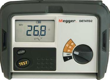
22 Four-Point Resistivity Tester Also Tests Resistance 22
23 Why Measure Soil Resistivity Periodically? To check that climatic conditions have not changed the ground such that it no longer meets the requirements To check for seasonal variations To check that changes to buildings, the lot, the streets, etc. have not affected resistivity 23
24 Ground Resistance Ground Resistance: The resistance (opposition to current flow) of an installed electrode system 24
25 Typical Permissible Ground Resistance Values Telecom - varies depending on the standard used: - Electronic equip mfg. vary from fraction of an ohm upward -At premise must equalize with power ground which is 25Ω Typical values from an insurance company: - Industrial plant: 5 - Chemical plant: 3 - Computer system: 3 Typical values for a power company: - Generating station: 1 maximum - Large sub-station: 1 maximum - Small sub-station: 5 maximum Why 25 Ohms? 25

26 25 Ohm ground keeps US safe NEC Section 250 IEEE STD 81 26
27 Ground Electrode System Components Ground Electrodes Ground Conductors Ground Bars Bonding Connectors Mechanical Compression Welded 27
28 Ground Electrodes 28
29 Ground Electrodes Do Not Have To Be Rods Ground Electrode Types - Ground Plates Ground Rods: Copper Clad Steel Solid Copper Galvanized Stainless Steel Enhanced Ground Mesh 29
30 Ground Electrodes Types of Grounding Systems Multiple-Rod Electrode Single Rod Electrode Multiple Pole Grounds 30
31 Ground Electrodes Utility Pole Ground Wire 12 below ground Butt Plate? Ground Rod 31

32 Another type of butt ground 32
33 Ground Electrodes Considerations Soil Resistivity - Some soils, (such as sandy soils), have such high resistivity that conventional ground rods or ground electrode systems may be unable to attain the desired ground resistance. Enhanced ground electrodes or ground enhancement materials may be required to meet the grounding specification. Some of these are 33
34 Enhanced Ground Electrodes Ufer Grounds - Concrete encased electrode tying into tower footing or building-pad rebar 34

35 Enhanced Grounding Material Low Resistance Reduces seasonal variation Carbon-based Not permanent Washes away over time Only consider when deep or multiple rods are not practical 35
36 Enhanced Grounding Material Soil treating material placed in circular trench and covered with earth Appx 1 ft. Ground rod Appx 18 in. 36


37 Enhanced Grounding Material 37

38 Ground Electrodes Considerations Soil Ph - affects the rate of corrosion of metal ground components that are in contact with the soil cont. 38
39 Ground Electrodes Considerations Soil Characteristics - Some sites may have only a few inches of soil (or none) sitting on top of bedrock. Consider- Ground mesh & plates Horizontal rods (Don t drill into bedrock such as granite. Such rock does not make a good ground.) cont. 39
40 Ground Rods Considerations Ground Rod Diameter Doubling diameter of ground rod reduces resistance only 10%. Using larger diameter ground rods is mainly a strength issue. In rocky conditions, a larger diameter ground rod might be advantageous. Cont. 40
41 Ground Rods Considerations Ground Rod Length - Doubling length theoretically reduces resistance 40%. Actual reduction depends on soil resistivities of multi-layered soils. Cont. 41
42 Ground Rods Considerations Multiple Ground Rods Two well-spaced rods driven into the ground provide parallel paths. They are, in effect, two resistances in parallel. The rule for two resistances in parallel does not apply exactly. (The resultant resistance is not one-half of one of the rod s resistance.) The reduction for equal resistance rods is about: 40 percent for 2 rods 60 percent for 3 rods 66 percent for 4 rods Spaced apart greater than their length 42


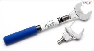
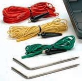
43 What Else Can YOU Control? Torque Bullet Bonds 43


44 Which kind does your locate contractor use? 44
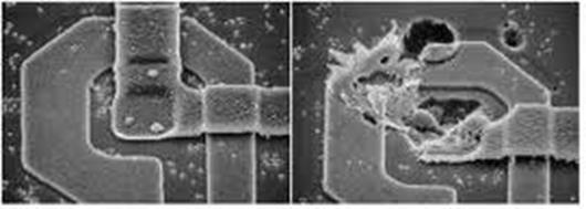
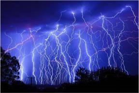
45 Causes of Ground System Deterioration Weather influences exert mechanical strain on ground rods Cable locates Corrosion over time Catastrophic events like lightning strikes or large fault currents can cause instant degradation that may not be visible Soil resistivity can change over time due to environmental conditions Facility expansion can create different needs in the ground system 45
46 Risks from Ground System Deterioration Potentially deadly electrical shock situations Plant-wide equipment damage Disruption in the performance of sensitive equipment with tight voltage parameters Heat build-up on a single piece of electrical equipment and, eventually, fire 46
47 Ground Electrode System Testing Ok, the system is designed and installed. Let s Test! 47
48 Choose the Proper Instruments Use a dedicated ground tester - designed to measure grounds Don t use a generalized ohmmeter or multimeter Don t use an insulation resistance tester Don t use the ground test of a telecom multifunction test set 48
49 Safety First! This is not a safety course 49
50 Three-Terminal Ground-Resistance Testing 50
51 Review Ohm s Law Resistance = Voltage Current Ohms = Volts Amps If we know Voltage and Current, we can calculate Resistance So, If we have 50 Volts and 2 Amps, we have 25 Ohms (25 = 50 2) 51
52 Three-Terminal Ground Resistance Tester Current Supply Ammeter (I) Ground Rod Under Test (Isolated) Voltmeter (E) Potential Probe P Current Probe C X Earth Earth 52
53 Fall of Potential Ground Rod Under Test (X) (Isolated) Ground Rod Position 53
54 Resistance in Ohms Resistance Curve True Resistance X Ground Rod Position Distance of Potential Probe from X C Current Probe Position 54
55 Rules of Thumb on C Probe Spacing From Ground Rod X Single ground rod - 50 feet Small grid of 2 ground rods feet Large system (several rods or plates in parallel) >200 feet Complex systems (large number of rods or other electrodes and other metallic structures bonded together) - far greater distances are required 55
56 Resistance in Ohms Insufficient Probe Spacing Ground Rod Under Test (X) (Isolated) Potential Probe (P) Current Probe (C) No Flattening No True Resistance Distance of Potential Probe from X 56
57 Advantage: Advantages/Disadvantages of Fall of Potential Testing Conforms to IEEE 81 - only approved method. Disadvantage: Time consuming 57
58 61.8% Rule Ground Rod Under Test (X) (Isolated) 61.8% Ground Rod Position 58
59 61.8% Rule/Method Based on the full Fall of Potential method Take measurement at only one point Advantage Quick and easy Disadvantage Assumes that conditions are perfect with respect to: Adequate spacing of C and P probes Resistivity of the soil being the same 59
60 Ground Testing on Asphalt Lazy Spike Does not have to be wet (Isolated) MEGGER DET5/4R 3 POLE 4 POLE MEASURE 60
61 Ground Testing Methods Fall of Potential Method* 61.8% Rule Method* Simplified Fall of Potential Four Potential Method Intersecting Curves Method Slope Method Dead Earth Method Star-Delta Method *Covered here 61
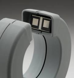
62 Stake-less or Clamp Ground Testing 62
63 Review Ohm s Law Resistance = Voltage Current Ohms = Volts Amps If we know Voltage and Current, we can calculate Resistance So, If we have 50 Volts and 2 Amps, we have 25 Ohms (25 = 50 2) 63
64 64

65 CAUTION Ammeter does not measure the value of the ground 65
66 Considerations When Using Stake-less/Clamp-On Method Effective only in situations with multiple grounds in parallel such as pole grounds 66
67 Multiple Grounds in Parallel 67
68 Considerations When Using Stake-less/Clamp-On Method Effective only in situations with multiple grounds in parallel such as pole grounds Requires a good return path so it cannot be used on isolated grounds 68
69 Clamp Won t Work No Return Path CATIV n600v Megger 69
70 Considerations When Using Stake-less/Clamp-On Method Effective only in situations with multiple grounds in parallel such as pole grounds Requires a good return path so it cannot be used on isolated grounds Cannot be used if an alternate, lower resistance, return path exists not involving the soil 70

71 Must Measure at the Correct Part of the Loop Connecting Wire Lightning Rods CATIV n600v Megger 71


72 Power Company Feed NID What is being measured? Clamp-on set must be BELOW this point. To power company ground (Has many parallel connections to power company feed.) 6 Rods are 6 to 8 apart Multiple ground rods bonded underground 72

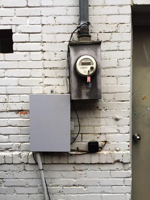
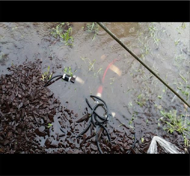
73 Reality 73

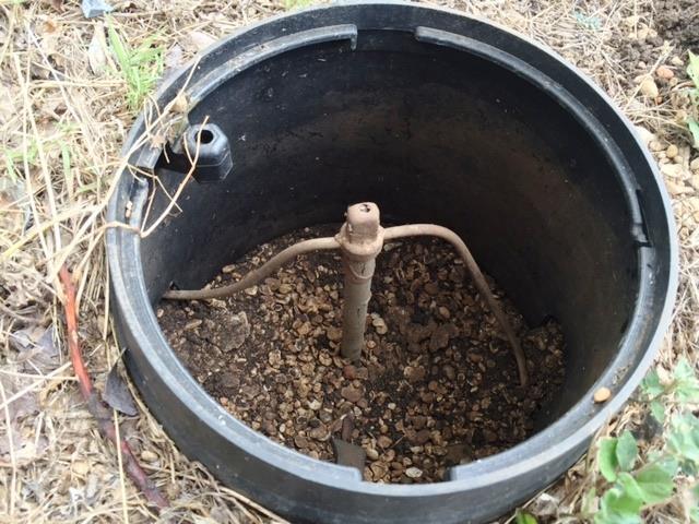
74 What is Being Measured? Grounding Conductor Bonded to MGN Utility Pole Butt Plate Ground Rod 74


75 What is Being Measured? Only Connectivity Not Ground Resistance Wire Connecting Each Leg to Rod Ground Rods At Each Leg CATIV n600v Megger Buried Wire Connecting the Rods 75

76 Pedestal Ground Bus SHIELD CONNECTION Ground Bar 76
77 CATIV n600v Megger Ground bar Measuring continuity 77

78 This is what the ground wires look like that we have to clamp around to test. Right? 78

79 Sometimes It s Not Easy 79
80 80

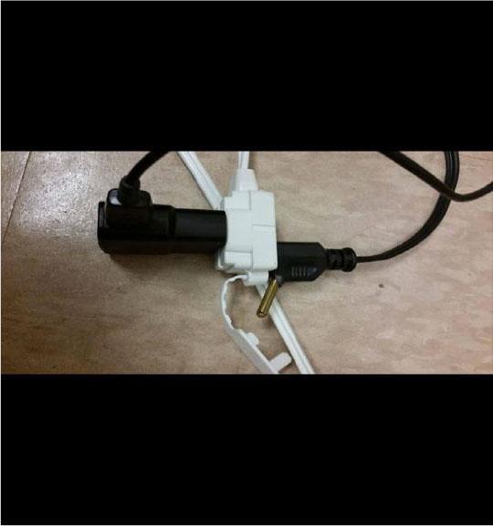
81 What Now? Could be worse 81
82 82
83 Quick Review 83
84 Addressing Ground System Problems Use longer ground rods Use multiple ground rods Chemically treat the soil Place the system in lower resistivity soil if possible 84
85 So, we tested our ground system and we passed! Do we ever need to test it again? 85
86 Why Measure Ground Resistance Periodically? (You have seen this before but ) To determine the effectiveness of ground rods and connections Seasonal changes Water table changes Changes in the site and/or building To check that standards set by codes are still being met To check that specific design parameters have been met To check that the ground rods and bonds are still present 86
87 Questions 87
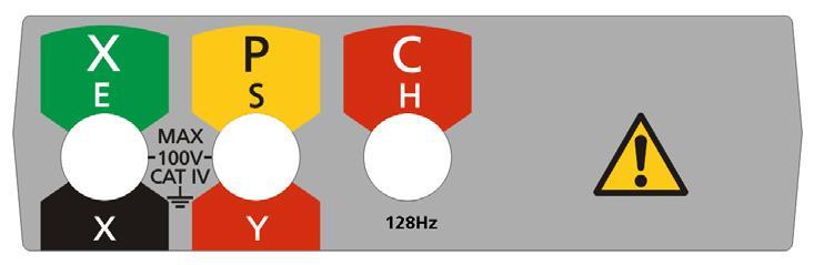
UNDERSTANDING. Ground Resistance Testing. Soil Resistivity. Ground Resistance. 3-Point Measurements. 4-Point Measurements. Clamp-On Measurements
 UNDERSTANDING Ground Resistance Testing Current supply E Ammeter (I) I Voltmeter (E) Ground electrode under test X Auxiliary potential electrode Y Auxiliary current electrode Z R Rx R1 R2 Rn-1 Rn EARTH
Safety Issues Caused by High Earth Resistance and Identifying Them Using Instruments
 Safety Issues Caused by High Earth Resistance and Identifying Them Using Instruments Thomas Szollossy Senior Technical Support Engineer Power Quality Thailand PQSynergy 2017, Chiang Mai, Thailand Introduction
Grounding for Power Quality
 Presents Grounding for Power Quality Grounding for Power Quality NEC 250.53 states that ground resistance should be less than 25 ohms. Is this true? Grounding for Power Quality No! NEC 250.53 states
Appendix. Appendix. Getting Down to Earth. AVO, International NJATC 07
 IBEW NECA Appendix ATTITUDE SKILL KNOWLEDGE FOR APPRENTICESHIP & TRAINING THE ELECTRICAL INDUSTRY Appendix Getting Down to Earth AVO, International Appendix IBEW NECA ATTITUDE SKILL KNOWLEDGE FOR APPRENTICESHIP
Understand the importance of Ground Resistance Testing & much more! (800) (508)
 (508)") Soil Resistivity Ground Resistance 3-Point Measurements 4-Point Measurements Clamp-On Measurements Understand the importance of Ground Resistance Testing & much more! (800) 343-1391 (508) 698-2115 www.aemc.com
Soil Resistivity Ground Resistance 3-Point Measurements 4-Point Measurements Clamp-On Measurements Understand the importance of Ground Resistance Testing & much more! (800) 343-1391 (508) 698-2115 www.aemc.com
Industrial and Commercial Power Systems Topic 7 EARTHING
 The University of New South Wales School of Electrical Engineering and Telecommunications Industrial and Commercial Power Systems Topic 7 EARTHING 1 INTRODUCTION Advantages of earthing (grounding): Limitation
EPG. by Chris C. Kleronomos
 April 1994 EFFECTIVE EQUIPMENT GROUNDING ECOS Electronics Corporation by Chris C. Kleronomos The quality of the electrical wiring and grounding in a facility containing sensitive electronic equipment is
High Voltage Pylon Earth Measurements
 High Voltage Pylon Earth Measurements Speaker: Gavin van Rooy Authors: Frank Barnes and Gavin van Rooy Tycom (Pty) Ltd PO Box 3546, Randburg, 2125, South Africa E-mail: frank@tycom.co.za Phone: 011 787
High Voltage Pylon earth Measurements. Tycom (Pty) Ltd Frank Barnes Comtest (Pty) Ltd Presented by Gavin van Rooy
 Ltd Frank Barnes Comtest (Pty) Ltd Presented by Gavin van Rooy") High Voltage Pylon earth Measurements Tycom (Pty) Ltd Frank Barnes Comtest (Pty) Ltd Presented by Gavin van Rooy Abstract The earth connection of high voltage electrical power line pylons is obviously
High Voltage Pylon earth Measurements Tycom (Pty) Ltd Frank Barnes Comtest (Pty) Ltd Presented by Gavin van Rooy Abstract The earth connection of high voltage electrical power line pylons is obviously
Harger Lightning & Grounding. *Grounding and Bonding* The Foundation For Effective Electrical Protection
 Harger Lightning & Grounding *Grounding and Bonding* The Foundation For Effective Electrical Protection Objectives 1. Define the difference between grounding & bonding and to describe the roles they play
PRACTICAL PROBLEMS WITH SUBSTATION EARTHING
 1 PRACTICAL PROBLEMS WITH SUBSTATION EARTHING Dr Hendri Geldenhuys Craig Clark Eskom Distribution Technology This paper considers the issues around substation sites where the soil resistivity is of particularly
CONTINUING EDUC ATION
 3 CONTINUING EDUC ATION FOR WISCONSIN ELECTRICIANS 2017 NEC Article 250 2 Hours WISCONSIN CONTRACTORS INSTITUTE N16 W23217 Stone Ridge Drive Suite 290 Waukesha, WI 53188 262-409-4282 www.wcitraining.com
2/15/2015. Current will always try to return to its source. In order for there to be current, there must be a complete circuit
 Current will always try to return to its source In order for there to be current, there must be a complete circuit Current will take as many paths or circuits available to it to return to the source The
GOOD GROUNDING PRACTICES. A Brief Introduction to the Basics of Electrical Grounding for Power Systems
 GOOD GROUNDING PRACTICES A Brief Introduction to the Basics of Electrical Grounding for Power Systems Introduction to Grounding TABLE OF CONTENTS 1.0 Introduction to Grounding 2.0 Standard Industrial Grounding
American Electrical Institute
 American Electrical Institute Oregon Electricians Continuing Education Grounding & Bonding (Article 250) 4 Hours American Electrical Institute PO Box 31131 Spokane, WA 99223 www.aeitraining.com Article
Article 250 Grounding & Bonding
 Article 250 Grounding & Bonding AMERICAN ELECTRICAL INSTITUTE N16 W23217 Stone Ridge Dr. Waukesha, WI 53188 855-780-5046 www.aeitraining.com DISCLAIMER NOTE: This course is APPROVED for continuing education
UNDERSTANDING. Ground Resistance Testing. I Voltmeter (E) Grounding. electrode. under test. Ground rod and clamp
 Grounding. electrode. under test. Ground rod and clamp") UNDERSTANDING Ground Resistance Testing Current supply E Ammeter (I) I Voltmeter (E) Grounding electrode under test X Auxiliary potential electrode Y Auxiliary current electrode Z R Rx R1 R2 Rn-1 Rn EARTH
UNDERSTANDING Ground Resistance Testing Current supply E Ammeter (I) I Voltmeter (E) Grounding electrode under test X Auxiliary potential electrode Y Auxiliary current electrode Z R Rx R1 R2 Rn-1 Rn EARTH
SDCS-03 DISTRIBUTION NETWORK GROUNDING CONSTRUCTION STANDARD (PART-I) UNDERGROUND NETWORK GROUNDING. Rev. 01
 UNDERGROUND NETWORK GROUNDING. Rev. 01") SDCS-03 DISTRIBUTION NETWORK GROUNDING CONSTRUCTION STANDARD (PART-I) UNDERGROUND NETWORK GROUNDING Rev. 01 This specification is property of SEC and subject to change or modification without any notice
SDCS-03 DISTRIBUTION NETWORK GROUNDING CONSTRUCTION STANDARD (PART-I) UNDERGROUND NETWORK GROUNDING Rev. 01 This specification is property of SEC and subject to change or modification without any notice
Outdoor Installation 2: Lightning Protection and Grounding
 Outdoor Installation 2: Lightning Protection and Grounding Training materials for wireless trainers This one hour talk covers lightning protection, grounding techniques and problems, and electrolytic incompatibility.
Tower and Station Grounding
 Tower and Station Grounding Southwest Dallas County Amateur Radio Club 1/17/2017 Presented By Maurice Martin KM5RF Why Ground? What You Don't Want! During lightning, the surrounding air is immediately
SDCS-03 DISTRIBUTION NETWORK GROUNDING CONSTRUCTION STANDARD GROUNDING RESISTANCE MEASUREMENTS AND IMPROVEMENT
 SEC DISTRIBUTION GROUNDING STANDARD SDCS-03 DISTRIBUTION NETWORK GROUNDING CONSTRUCTION STANDARD (PART-III) REV-01 GROUNDING RESISTANCE MEASUREMENTS AND IMPROVEMENT This specification is property of SEC
National Radio Astronomy Observatory Socorro, NM EVLA Memorandum 41 Lightning Protection for Fiber Optic Cable. T. Baldwin June 05, 2002
 National Radio Astronomy Observatory Socorro, NM 87801 EVLA Memorandum 41 Lightning Protection for Fiber Optic Cable T. Baldwin June 05, 2002 Summary Double-armor triple-sheath fiber optic cable will be
Importance of Grounding in Power System. Presented by Mr. H Jayakumar Ex- Joint Director CPRI
 Importance of Grounding in Power System Presented by Mr. H Jayakumar Ex- Joint Director CPRI OBJECT OF EARTHING Prime Object of Earthing is to Provide a Zero Potential Surface in and around and under the
SAFETY AND HEALTH STANDARD ELECTRICAL GROUNDING Effective Date: 07/17/10 Standard: Document Number: KUCSH0039 Rev: 4
 SAFETY AND HEALTH STANDARD ELECTRICAL GROUNDING Effective Date: 07/17/10 Standard: 16.10 Document Number: KUCSH0039 Rev: 4 16.10.1 INTRODUCTION 16.10.1.1 The intent of this standard is to ensure that continuity
Grounding Recommendations for On Site Power Systems
 Grounding Recommendations for On Site Power Systems Revised: February 23, 2017 2017 Cummins All Rights Reserved Course Objectives Participants will be able to: Explain grounding best practices and code
Best Practices for Power and Transient Protection on Rosemount Radar Transmitters
 Technical Note Rosemount Radar Transmitters Best Practices for Power and Transient Protection on Rosemount Radar Transmitters BACKGROUND INTRODUCTION This document describes best practices for power and
Stake-less earth / ground testing
 APPLICATION NOTE Stake-less earth / ground testing NEW DET14C and DET24C CLAMPS GETTING-AROUND ANY CHALLENGE What is stake-less testing? How does it work? Where and how can it be used? What are the potential
White Paper Security Cameras, CATV, GPS and Satellite Protection
 White Paper Security Cameras, CATV, GPS and Satellite Protection 1485-042 White Paper Security Cameras, CATV, GPS and Satellite Protection Security Cameras, CATV, GPS & Satellite Protection Outdoor Closed
Safety earthing. Sector Energy PTI NC. Copyright Siemens AG All rights reserved. Theodor Connor
 Safety earthing Sector Energy PTI NC Theodor Connor Copyright Siemens AG 2008. All rights reserved. Content Introduction Theoretical background Soil Analysis Design of earthing system Measurements on earthing
RADIO AND TELEVISION SATELLITE EQUIPMENT
 ARTICLE 810 RADIO AND TELEVISION SATELLITE EQUIPMENT Introduction to Article 810 Radio and Television Satellite Equipment This article covers transmitter and receiver (antenna) equipment and the wiring
Grounding and Lightning arrestors
 CHAPTER - Four Grounding and Lightning arrestors 4.1. Introduction Electrical connection of neutral point of a supply system or the non current carrying part of electrical equipments to the general mass
Asset Protection Cathodic Protection Soil Resistivity Measurement. Work Instruction No.:
 Asset Protection Cathodic Protection Soil Resistivity Measurement Approved by: Manager Pipeline Standards 1 PURPOSE This work instruction describes the processes to be followed when measuring soil resistivity.
Stray Voltage and Swimming Pools
 Stray Voltage and Swimming Pools Marty L. Page, P.E. Southern Company malpage@southernco.com October 19 th 2009 2009 Jodie Lane National Conference for Stray Voltage Detection, Mitigation & Prevention
AC Voltage- Pipeline Safety and Corrosion MEA 2015
 AC Voltage- Pipeline Safety and Corrosion MEA 2015 WHAT ARE THE CONCERNS ASSOCIATED WITH AC VOLTAGES ON PIPELINES? AC concerns Induced AC Faults Lightning Capacitive coupling Safety Code Induced AC Corrosion
GROUND TESTERS For all of your Ground Testing needs...
 GROUND TESTERS For all of your Ground Testing needs... An array of Ground Testers to choose from Whether you are doing a simplified 2-Point, a more complete 3- or 4-Point Fall-of-Potential test, a soil
DET4 Series. 4-Terminal Earth/Ground Resistance and Soil Resistivity Testers. DET4 Series Earth/Ground Resistance & Soil Resistivity Testers
 4-Terminal Earth/Ground Resistance and Soil Resistivity Testers DET4 Series 2, 3 and 4 point testing Stakeless (clamp-on) testing capability ART (Attached Rod Technique) capability Multiple, user selectable
Wisconsin Contractors Institute Continuing Education
 IMPORTANT NOTE: You should have received an email from us with a link and password to take your final exam online. Please check your email for this link. Be sure to check your spam folder as well. If you
SDCS-03 DISTRIBUTION NETWORK GROUNDING CONSTRUCTION STANDARD (PART-II) OVERHEAD NETWORK GROUNDING. Rev. 01
 OVERHEAD NETWORK GROUNDING. Rev. 01") SEC DISTRIBUTION GROUNDING STANDARD SDCS-03 Part-II Rev.01 SDCS-03 DISTRIBUTION NETWORK GROUNDING CONSTRUCTION STANDARD (PART-II) OVERHEAD NETWORK GROUNDING Rev. 01 This specification is property of SEC
SEC DISTRIBUTION GROUNDING STANDARD SDCS-03 Part-II Rev.01 SDCS-03 DISTRIBUTION NETWORK GROUNDING CONSTRUCTION STANDARD (PART-II) OVERHEAD NETWORK GROUNDING Rev. 01 This specification is property of SEC
Lightning Strikes. Presented to the Greater Norwalk Amateur Radio Corporation Inc. February 8, 2017 Steven M. Simons W1SMS
 Lightning Strikes Presented to the Greater Norwalk Amateur Radio Corporation Inc. February 8, 2017 Steven M. Simons W1SMS ARRL CT State Technical Coordinator The Power of Lightning What is a Ground? Design
Earth Grounding Resistance
 Earth Grounding Resistance Principles, testing methods and applications DIAGSE intermittent electrical problems AVOID unnecessary downtime LEARN earth ground safety principles Why ground, why test? Why
Understanding Ground Resistance Testing
 Understanding Ground Resistance Testing CURRENT SUPPLY E I AMMETER (I) VOLTMETER (E) X AUXILIARY POTENTIAL ELECTRODE Y AUXILIARY CURRENT ELECTRODE Z Rx R1 R2 Rn-1 Rn Ground Rod and Clamp Resistance in
Understanding Soil Resistivity Testing
 Technical Hotline: (0) -9 Technical Hotline: (0) -9 www.aemc.com www.aemc.com Understanding Testing Effects of on Ground Electrode Resistance Factors Affecting APPLICATION NOTES OCTOBER Understanding Testing
GROUNDING. What is it? Al Lewey K7ABL. Disclaimer
 GROUNDING What is it? Al Lewey K7ABL Disclaimer Disclamier Mechanical Engineer with some electrical background My primary reference is References UP THE TOWER The Complete Guide to Tower Construction By
FAQ ON EARTHING STANDARDS 16/08/2018
 FAQ ON EARTHING STANDARDS 16/08/2018 This document has been updated to include changes made to substation earthing layouts that have been made necessary due to copper theft. The main changes to be aware
Grounding Essentials for the Shack
 Grounding Essentials for the Shack Lightning Protection AC Power Safety RF Grounding (RF feedback - Tx) RF Noise (RFI - Rcvr) 2014/2015 * What is Lightning? 30-50 million volts 18,000 Amps Xenon lights
LIGHTNING EARTHING SYSTEM : A PRACTICAL GUIDE
 International Lightning Protection Association 1 st Symposium Valencia Spain 24th 25th of November, 2011 LIGHTNING EARTHING SYSTEM : A PRACTICAL GUIDE Alain Rousseau SEFTIM (France) ABSTRACT To make a
Soil Resistivity Ground Resistance 3-Point Measurements 4-Point Measurements Clamp-On Measurements
 Soil Resistivity Ground Resistance 3-Point Measurements 4-Point Measurements Clamp-On Measurements 200 Foxborough Blvd. Foxborough, MA 02035 (800) 343-1391 (508) 698-2115 FAX (508) 698-2118 sales@aemc.com
HV Substation Earthing Design for Mines
 International Journal of Engineering Research and Development e-issn: 2278-067X, p-issn: 2278-800X, www.ijerd.com Volume 4, Issue 6 (October 2012), PP. 100-107 HV Substation Earthing Design for Mines M.
Lightning Protection. Wisconsin Broadcasters Association Broadcasters Clinic. 14 th October 2009 Jeff Welton Regional Sales Manager, Central U.S.
 Lightning Protection Wisconsin Broadcasters Association Broadcasters Clinic 14 th October 2009 Jeff Welton Regional Sales Manager, Central U.S. Nautel Limited 2009 This presentation has been produced for
Need for grounding Codes and Standards for grounding Wind Turbine Generator grounding design Foundation + Horizontal Electrode grounding design
 IEEE PES Transmission and Distribution Conference 2008 Panel Session Large Wind Plant Collector Design Wind Farm Collector System Grounding by Steven W. Saylors, P.E. Chief Electrical Engineer Vestas Americas
from ocean to cloud LAND CABLE INTERFERENCE MODEL AND CABLE CROSSINGS WITH POWER INTERCONNECTS
 LAND CABLE INTERFERENCE MODEL AND CABLE CROSSINGS WITH POWER INTERCONNECTS Mr. Ritesh Dass (Cable&Wireless Worldwide) Email: ritesh.dass@cw.com Cable&Wireless Worldwide, 32-43 Chart Street, London, N1
GROUNDED ELECTRICAL POWER DISTRIBUTION. Excerpt from Inverter Charger Series Manual BY: VIJAY SHARMA ENGINEER
 GROUNDED ELECTRICAL POWER DISTRIBUTION Excerpt from Inverter Charger Series Manual BY: VIJAY SHARMA ENGINEER .0 Conductors for Electrical Power Distribution For single-phase transmission of AC power or
Cisco Aironet 13.5-dBi Yagi Mast Mount Antenna (AIR-ANT1949)
") Cisco Aironet 13.5-dBi Yagi Mast Mount Antenna (AIR-ANT1949) Overview This document describes the 13.5-dBi Yagi mast mount antenna and provides instructions for mounting it. The antenna operates in the
Cisco Aironet 13.5-dBi Yagi Mast Mount Antenna (AIR-ANT1949) Overview This document describes the 13.5-dBi Yagi mast mount antenna and provides instructions for mounting it. The antenna operates in the
Surge Protection and Grounding Issues
 Surge Protection and Grounding Issues Presented to SCTE Chicago Chapter January 21, 2004 By: Nisar Chaudhry VP Electrical Engineering, CTO Introduction Transients caused by disturbances on the power lines
Electrical TP-18 February 2017 ELECTRICAL TECHNICAL PAPER 18 FREQUENTLY ASKED QUESTIONS ABOUT CATHODIC PROTECTION SYSTEM EQUIPMENT TESTING
 ELECTRICAL TECHNICAL PAPER 18 FREQUENTLY ASKED QUESTIONS ABOUT CATHODIC PROTECTION SYSTEM EQUIPMENT TESTING CATHODIC PROTECTION SYSTEM EQUIPMENT TESTING Question No. 1 What should I (the contractor) check
Equipment Rack Grounding. Technical Note
 Equipment Rack Grounding Technical Note Equipment Rack Grounding Surge Protection Solutions for PTC 1 Equipment Rack Grounding Equipment racks and cabinets can provide an unwanted path for lightning surge
Overview of Grounding for Industrial and Commercial Power Systems Presented By Robert Schuerger, P.E.
 Overview of Grounding for Industrial and Commercial Power Systems Presented By Robert Schuerger, P.E. HP Critical Facility Services delivered by EYP MCF What is VOLTAGE? Difference of Electric Potential
To Float or Not to Float? Analysis of a floating vs. grounded output Associated Power Technologies
 To Float or Not to Float? Analysis of a floating vs. grounded output Associated Power Technologies Introduction In electrical circuits, voltage is always measured between two points: a point of high potential
BUILD A HIGH PERFORMANCE TWO ELEMENT TRI-BAND CUBICAL QUAD. By Bob Rosier K4OCE INTRODUCTION THEORY AND GENERAL INFORMATION
 BUILD A HIGH PERFORMANCE TWO ELEMENT TRI-BAND CUBICAL QUAD INTRODUCTION By Bob Rosier K4OCE Lots of DX can be worked with a dipole at the QRP level, however, a beam will obviously give you additional gain
Grounding and Bonding
 Grounding and Bonding 2017 Communications Academy Joe Blaschka Jr., PE Grounding/Bonding What is it? Why do we do it? What does the National Electrical Code say? What about fixed locations? What about
Telephone Cable Locating Techniques
 Chapter 2 Telephone Cable Locating Techniques Introduction Read Chapter One of this manual to learn more general information about each of the following signal application methods. The following paragraphs
There are a wide variety of ground resistance testers available on the
 Featured Products: Choosing the Right Ground Resistance Tester There are a wide variety of ground resistance testers available on the market today. These vary in design, features, and complexity, and include
K e e l i n g C o m p a n y
 e e l i n g C o m p a n y GOLF IRRIGATION WIRE Page 87 GOLF IRRIGATION WIRE e e l i n g C o m p a n y Page 88 e e l i n g C o m p a n y It is the responsibility of the installer to connect all electronic
NEW OR UPGRADED ELECTRICAL SERVICE
 NEW OR UPGRADED ELECTRICAL SERVICE The following steps summarize the general process and procedures necessary for CVEA to complete construction of a new or upgraded service. Variances may be necessary
SPECIAL SPECIFICATION LIGHTNING PROTECTION SYSTEM
 2004 Specifications CSJ 3622-01-001, ETC. SPECIAL SPECIFICATION 8398 LIGHTNING PROTECTION SYSTEM 1. Description. This Special Specification governs the design and installation of Lightning Protection System
A Case Study on Selection and Application of Lightning Arrester and Designing its Suitable Grounding Grid
 A Case Study on Selection and Application of Lightning Arrester and Designing its Suitable Grounding Grid 1 Arpan K. Rathod, 2 Chaitanya H. Madhekar Students Electrical Engineering, VJTI, Mumbai, India
Overvoltage Protection
 Overvoltage Protection S T U D E N T M A N U A L March 31, 2005 2 STUDENT TRAINING MANUAL Prerequisites: Single-Phase Transformer Load Checks Objectives: From memory, you will be able to describe the electrical
Topic 6 Quiz, February 2017 Impedance and Fault Current Calculations For Radial Systems TLC ONLY!!!!! DUE DATE FOR TLC- February 14, 2017
 Topic 6 Quiz, February 2017 Impedance and Fault Current Calculations For Radial Systems TLC ONLY!!!!! DUE DATE FOR TLC- February 14, 2017 NAME: LOCATION: 1. The primitive self-inductance per foot of length
National Marine Manufacturers Association Compliance Specialist Examination A.C. Electrical (2018 Model Year) ABYC E-11 Supplement 56
 ABYC E-11 Supplement 56") 1. Two Electrical Technicians are discussing markings that are required for AC wiring. Tech A says that AC conductors must be rated for 600 volts and must have their jackets and individual conductors marked
1. Two Electrical Technicians are discussing markings that are required for AC wiring. Tech A says that AC conductors must be rated for 600 volts and must have their jackets and individual conductors marked
Lesson 11: Antennas. Copyright Winters Version 1.0. Preparation for Amateur Radio Technician Class Exam
 Lesson 11: Antennas Preparation for Amateur Radio Technician Class Exam Topics Antenna ½ wave Dipole antenna ¼ wave Vertical antenna Antenna polarization Antenna location Beam antennas Test Equipment Exam
Minimizing Lightning and Static Discharge in Broadcasting
 Minimizing Lightning and Static Discharge in Broadcasting Lightning and static discharge represent two of the most damaging and unpredictable events faced by broadcasters. Together or separately they are
Tower Grounding Training For Telecommunications Networks
 Tower Grounding Training For Telecommunications Networks Contact us Today for a FREE quotation to deliver this course at your company?s location. https://www.electricityforum.com/onsite-training-rfq The
Customer Requirements RF Antenna Installations
 Application Terms Attachment requirements and clearances on the Pole for Radio Frequency (RF) antenna equipment installations. This standard is intended to allow electrical workers to perform their normal
Electrical Wiring: Commercial, Seventh Canadian Edition
 Electrical Wiring Commercial Canadian 7th Edition Mullin SOLUTIONS MANUAL Full download at: https://testbankreal.com/download/electrical-wiring-commercialcanadian-7th-edition-mullin-solutions-manual/ Unit
Ten-Tec Model 3402 and 3403 Broadband Antennas Installation and Operation Manual PN 74393
 1. Introduction Ten-Tec Model 3402 and 3403 Broadband Antennas Installation and Operation Manual PN 74393 The Ten-Tec Model 3402 Broadband Terminated Vee Beam Antenna offers continuous coverage between
A DUMMIES GUIDE TO GROUND FAULT PROTECTION
 A DUMMIES GUIDE TO GROUND FAULT PROTECTION A DUMMIES GUIDE TO GROUND FAULT PROTECTION What is Grounding? The term grounding is commonly used in the electrical industry to mean both equipment grounding
UNITED STATES OF DEPARTMENT OF AGRICULTURE Rural Utilities Service BULLETIN 1751F-815. Electrical Protection of Outside Plant
 UNITED STATES OF DEPARTMENT OF AGRICULTURE Rural Utilities Service BULLETIN 1751F-815 SUBJECT: TO: Electrical Protection of Outside Plant All Telecommunications Borrowers RUS Telecommunications Staff EFFECTIVE
Helical Pier Frequently Asked Questions
 Helical Pier Basics Q: What is a Helical Pier? A: A helical pier or pile is an extendable deep foundation system with helical bearing plates welded to a central steel shaft. Load is transferred from the
Upgrading Your Electrical Distribution System To Resistance Grounding
 Upgrading Your Electrical Distribution System To Resistance Grounding The term grounding is commonly used in the electrical industry to mean both equipment grounding and system grounding. Equipment grounding
SECTION TRACER WIRE FOR NONMETALLIC PIPE
 PART 1 GENERAL 1.1 DESCRIPTION A. The CONTRACTOR shall furnish and install a conductive tracer wire with all buried plastic water mains, services and appurtenances in accordance with the Water Utilities
GROUND RESISTANCE TESTERS
 GROUND RESISTANCE TESTERS For all of your Ground Integrity Testing needs... An array of Ground Resistance Testers to choose from... Whether you are doing a simplified 2-Point, a more complete - or 4-Point
Troubleshooting accelerometer installations
 Troubleshooting accelerometer installations Accelerometer based monitoring systems can be tested to verify proper installation and operation. Testing ensures data integrity and can identify most commonly
EVALUATION OF THE EARTH RESISTANCE VALUE FOR ESE LIGHTNING ARRESTOR TECHNIQUE FOR THE SOLAR PLANTS IN INDIA
 EVALUATION OF THE EARTH RESISTANCE VALUE FOR ESE LIGHTNING ARRESTOR TECHNIQUE FOR THE SOLAR PLANTS IN INDIA Rajat Verma Project Engineer BHEL EDN, BANGALURU, MYSORE ROAD, KARNATAKA 560024, India ABSTRACT
Instruction Manual. TT1000 Tower Earth Tester. Rev 01
 Instruction Manual TT1000 Tower Earth Tester Rev 01 Contents 1 Introduction... 3 2 Features... 3 3 Operation... 4 3.1 Test Lead Configuration... 5 3.2 Probe Integrity Test... 6 3.3 Impedance measurement...
The Variable Threshold Neutral Isolator (VTNI)
") The Variable Threshold Isolator (VTNI) Installation Instructions INTRODUCTION The is designed specifically for installation between the primary neutral of a power utility distribution system and the secondary
The Variable Threshold Isolator (VTNI) Installation Instructions INTRODUCTION The is designed specifically for installation between the primary neutral of a power utility distribution system and the secondary
Earthing of Low Voltage Electrical Systems: Personnel Protection Equipment Protection
 ELEC9713 Industrial and Commercial Power Systems Earthing of Low Voltage Electrical Systems: Personnel Protection Equipment Protection 1. Introduction Earthing of electrical equipment and power systems
CONTINUOUS COUNTERPOISE ON POLES
 Project Procedure CONTINUOUS COUNTERPOISE ON POLES 07/25/2011 PAGE 1 OF 5 1.0 PURPOSE The purpose of this procedure is to provide guidance and direction for the installation of continuous counterpoise
Chapter 1. Applied Grounding and Bonding. Applied Grounding and Bonding 9/18/2011. Introduction. Introduction. Paul Dobrowsky Member NEC Panel 5
 Applied Grounding and Bonding Paul Dobrowsky Member NEC Panel 5 1 Introduction This presentation is a representative sample from the following Chapters of Applied Grounding and Bonding. Chapter 1, Introduction
EMC Philosophy applied to Design the Grounding Systems for Gas Insulation Switchgear (GIS) Indoor Substation
 Indoor Substation") EMC Philosophy applied to Design the Grounding Systems for Gas Insulation Switchgear (GIS) Indoor Substation Marcos Telló Department of Electrical Engineering Pontifical Catholic University of Rio Grande
EMC Philosophy applied to Design the Grounding Systems for Gas Insulation Switchgear (GIS) Indoor Substation Marcos Telló Department of Electrical Engineering Pontifical Catholic University of Rio Grande
SPECIFICATIONS FOR THE INSTALLATION OF CONDUIT SYSTEMS IN RESIDENTIAL SUBDIVISIONS. Notification of Completed Conduit Sections
 SPECIFICATIONS FOR THE INSTALLATION OF CONDUIT SYSTEMS IN RESIDENTIAL SUBDIVISIONS Section 1 Definitions 2 Scope of Work 3 Extent of Work 4 Inspection and Performance of Work 5 Trenching 6 Duct Installation
Cisco Aironet Omnidirectional Mast Mount Antenna (AIR-ANT2506)
") Cisco Aironet Omnidirectional Mast Mount Antenna (AIR-ANT2506) This document outlines the specifications, describes the omnidirectional mast mount antenna, and provides instructions for mounting it. Designed
Cisco Aironet Omnidirectional Mast Mount Antenna (AIR-ANT2506) This document outlines the specifications, describes the omnidirectional mast mount antenna, and provides instructions for mounting it. Designed
Earthing of Electrical Devices and Safety
 Earthing of Electrical Devices and Safety JOŽE PIHLER Faculty of Electrical Engineering and Computer Sciences University of Maribor Smetanova 17, 2000 Maribor SLOVENIA joze.pihler@um.si Abstract: - This
University of Jordan School of Engineering Electrical Engineering Department. EE 219 Electrical Circuits Lab
 University of Jordan School of Engineering Electrical Engineering Department EE 219 Electrical Circuits Lab EXPERIMENT 1 REPORT MEASUREMENT DEVICES Group # 1. 2. 3. 4. Student Name ID EXPERIMENT 1 MEASUREMENT
SOUTH DUBLIN COUNTY COUNCIL Traffic Management Centre Roads (Traffic and Transportation) Department
 Department") SOUTH DUBLIN COUNTY COUNCIL Roads (Traffic and Transportation) Department TECHNICAL SPECIFICATION 2 SDCC-TS-02 INDUCTIVE LOOPS & ABOVE GROUND DETECTION REQUIREMENTS FOR THE DESIGN AND INSTALLATION OF TRAFFIC
SOUTH DUBLIN COUNTY COUNCIL Roads (Traffic and Transportation) Department TECHNICAL SPECIFICATION 2 SDCC-TS-02 INDUCTIVE LOOPS & ABOVE GROUND DETECTION REQUIREMENTS FOR THE DESIGN AND INSTALLATION OF TRAFFIC
SW Region Asset Specifications: Four Strand Barbed Wire Fence Specifications
 Lands Division Sustainable Resource Development SW Region Asset Specifications: Four Strand Barbed Wire Fence Specifications Prior to commencement of construction, contact must be made with the following
REQUIRED SKILLS AND KNOWLEDGE UEENEEE104A. Topic and Description NIDA Lesson CARD #
 REQUIRED SKILLS AND KNOWLEDGE UEENEEE104A KS01-EE104A Direct current circuits T1 Topic and Description NIDA Lesson CARD # Basic electrical concepts encompassing: electrotechnology industry static and current
Electrical Occupations
 Job Ready Assessment Blueprint Electrical Occupations Test Code: 3029 / Version: 01 Copyright 2011. All Rights Reserved. General Assessment Information Blueprint Contents General Assessment Information
Back to the Basics Current Transformer (CT) Testing
 Testing") Back to the Basics Current Transformer (CT) Testing As test equipment becomes more sophisticated with better features and accuracy, we risk turning our field personnel into test set operators instead of
Back to the Basics Current Transformer (CT) Testing As test equipment becomes more sophisticated with better features and accuracy, we risk turning our field personnel into test set operators instead of
Examples of Design for Cathodic Protection Systems
 Examples of Design for Cathodic Protection Systems CURRENT REQUIREMENTS From Estimated Exposed Surface Area Estimating current requirements from expected exposed surface is always subject to error. There
Device Interconnection
 Device Interconnection An important, if less than glamorous, aspect of audio signal handling is the connection of one device to another. Of course, a primary concern is the matching of signal levels and