EAST WEST UNIVERSITY
|
|
|
- Ferdinand McCarthy
- 6 years ago
- Views:
Transcription
 Submitted to the Department of Electrical and Electronic Engineering Faculty of Sciences and Engineering East West University In partial fulfillment of the requirements")
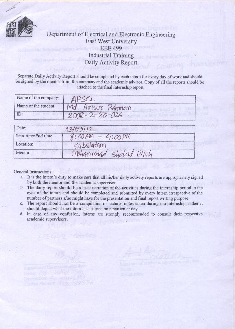
1 EAST WEST UNIVERSITY INTERNSHIP REPORT ON SUBSTATION OF ASHUGANJ POWER STATION COMPANY LIMITED (APSCL) By Md. Anisur Rahman: ( ) Submitted to the Department of Electrical and Electronic Engineering Faculty of Sciences and Engineering East West University In partial fulfillment of the requirements for the degree of Bachelor of Science in Electrical and Electronic Engineering (B.Sc. in EEE) Spring, 2013 Approved By Academic Advisor Anwarul Azim Lecturer Department Chairperson Dr. Mohammad Mojammel Al-Hakim Chairperson and Associate Professor
2 Training Certificate 2
3 Authorization Page I declare that I am the sole author of this internship report. I authorize East West University to lend this internship report to other institutions or individuals for the purpose of industrial attachment. I further authorize East West University to reproduce this internship report by photocopy or other means, in total or in part, at the request of other institutions or individuals for the purpose of industrial attachment. Md. Anisur Rahman 3
4 Approval Letter 4
5 Acknowledgement First of all I would like to thank the almighty Allah for giving me the chance to complete my internship and preparing the internship report. In the preparation of this internship report, I acknowledge the encouragement and assistance given by a number of people from Ashugonj Power Station Company Ltd. I am grateful to Engr. Md. Nurul Alam, Managing Director APSCL, Engr. Noor Mohammad, Manager (Substation), Engr. Md. Shahid Ullah, Assistant Engineer (Substation) and also Engr. Mohammad Kaium for their valuable suggestions and assurance. I would also like to thank my advisor Anwarul Azim, Lecturer, Department of Electrical & Electronic Engineering, East West University, Bangladesh. I would also like to mention the name of Dr. Mohammad Mojammel Al Hakim, Chairperson and Associate Professor of the Department of Electrical & Electronic Engineering, East West University and all of our teachers for their support. Lastly, I want to show our gratefulness to all the respondents who spared their precious time in answering our questionnaires. 5
6 Executive Summary The power sector in Bangladesh faced numerous problems characterized by lack of supply capacity, frequent power cuts, unacceptable quality of supply, and poor financial and operational performance of the sector entities. The generation of electricity is one of the most complex processes in the world. A lot of steps are needed to be completed to supply the power to the grid. In Bangladesh public and private sector produces 63% and 37% of electricity respectively. Public sector produces electricity through Bangladesh Power Development Board (BPDB), Ashuganj Power Station Company LTD (APSCL) and Electricity Generation Company of Bangladesh (EGCB). APSCL individually produces 15% of the total production. To fulfill the large demand of electric power in Bangladesh, the Ashuganj Power Station Company Ltd. (APSCL) plays a vital role in power generation being the second power station in Bangladesh. The APSCL produces 731 MW of electric power and supplies to the national grid. During our internship period we observed and gathered various knowledge and experiences over the topics which we have learned inside the class room or from books. In this report we have focused on the process which is used in APSCL for power generation, various equipments which are used for switchgear protection, power distribution system and substation. Substation is an important part of a power station to distribute power and protection purpose. We acquired knowledge about various types of transformers, bus-bars, circuit breakers (SF6 and Oil), lightning arresters, CT, PT and other equipments of the substation which were clearly taught and shown by the senior engineers of the substation of APSCL. There are various types of tests (Megger test, CT test, Relay test) which are performed by the technicians and engineers of the APSCL. With the help of the engineers and technicians we observed these tests successfully during our internship period. 6
7 Training Schedule Date Topic Mentor Time Duration Training Hour 24/08/2012 Introduce APSCL and Substation Engr. Md. Shahidullah Assistant Engineer (S/S) 8 am 1 pm 2 pm 4 pm 7 25/08/2012 Current Transformer (CT) Engr. Md. Shahidullah Assistant Engineer (S/S) 8 am 1 pm 2 pm 4 pm 7 26/08/2012 Feeder energize and de-energize Engr. Md. Shahidullah Assistant Engineer (S/S) 8 am 1 pm 2 pm 4 pm 7 27/08/2012 Battery Room Engr. Md. Shahidullah Assistant Engineer (S/S) 28/08/2012 Bus Coupler Engr. Md. Shahidullah Assistant Engineer (S/S) 29/08/2012 CT Testing Engr. Md. Shahidullah Assistant Engineer (S/S) 8 am 1 pm 2 pm 4 pm 8 am 1 pm 2 pm 4 pm 8 am 1 pm 2 pm 4 pm /08/2012 Potential Transformer (PT) Engr. Md. Shahidullah Assistant Engineer (S/S) 8 am 1 pm 2 pm 4 pm 7 31/08/2012 Isolator Maintenance Engr. Md. Shahidullah Assistant Engineer (S/S) 8 am 1 pm 2 pm 4 pm 7 01/09/2012 Single Phase Transformer Engr. Md. Shahidullah Assistant Engineer (S/S) 8 am 1 pm 2 pm 4 pm 7 02/09/2012 Circuit Breaker Engr. Md. Shahidullah Assistant Engineer (S/S) 8 am 1 pm 2 pm 4 pm 7 03/09/2012 Coupling Transformer Engr. Md. Shahidullah Assistant Engineer (S/S) 8 am 1 pm 2 pm 4 pm 7 04/09/2012 Different Switchgear Equipments Engr. Md. Shahidullah Assistant Engineer (S/S) 8 am 1 pm 2 pm 4 pm 7 05/09/2012 Auxiliary Transformers Engr. Md. Shahidullah Assistant Engineer (S/S) 8 am 1 pm 2 pm 4 pm 7 06/09/2012 Control Room Engr. Md. Shahidullah Assistant Engineer (S/S) 07/09/2012 Different types Relay Engr. Md. Shahidullah Assistant Engineer (S/S) 8 am 1 pm 2 pm 4 pm 8 am 1 pm 2 pm 4 pm 7 7 7
8 Page Contents TABLE OF CONTENTS CHAPTER 01: INTRODUCTION OF APSCL Introduction Company Profile Production Report Future projects of APSCL Objective of the Internship Scope And Methodology CHAPTER 02: INTRODUCTION OF SUBSTATION Introduction Main Equipment of the Substation Feeder Outgoing Feeder kv Outgoing Feeders kv Outgoing Feeders kv Outgoing Feeders kv Outgoing Feeders CHAPTER 03: TRANSFORMERS Introduction Types of Transformer Power Transformers Single Phase Transformer Earthing Transformer Auxiliary Transformer Coupling Transformer Transformer Protection Coolant Buchholz Relay Maintenance of a Power Transformer CHAPTER 04: INSTRUMENT TRANSFORMERS Introduction Current Transformer kv Voltage Level CT kv Voltage Level CT Current Transformer (CT) Testing Megger Test Primary Current Injection Potential Transformer kv Voltage Level PT kv Voltage Level PT CHAPTER 05: SWITCHGEAR PROTECTION & CONTROL SYSTEM Introduction Equipments of Switchgear Isolator
9 5.2.2 Bus Bar Lighting Arrester Sky Wire (Over Head Ground Wire) Insulators Pin Type Insulator Suspension Type Insulator Strain Insulator Wave Trap Earthling Switch Bus Coupler Circuit Breaker Oil Circuit Breaker: SF6 Circuit Breaker Protective Relay Differential Relay Over Current Relay Master Trip Relay Supervision Relay Auxiliary Relay Earth Fault Relay Restricted Earth Fault Relay Directional Relay Under Voltage Relay Relay Testing Battery Room Control Room CHAPTER 06: CONCLUSION Recommendations Discussion Reference: Appendix:
10 LIST OF FIGURES Figure 2.1: Power Generation and Distribution network at APSCL [7] Figure 2.2: Energy Balance Diagram of APSCL [8] Figure 2.4: Single Line Diagram of 230 kv Feeder of APSCL [8] Figure 2.5: Single Line Diagram of 132 kv Outgoing Feeder of APSCL [8] Figure 2.6: Single Line Diagram of 33 kv Feeder of APSCL [8] Figure 3.1: Single Phase Transformer at APSCL [7] Figure 3.2: Earthing Transformer at APSCL [7] Figure 3.3: Auxiliary Transformers at APSCL [7] Figure 3.4: Coupling Transformer between 132 kv and 230 kv Buses [7] Figure 3.5: Cooling Fans of Transformer at APSCL [7] Figure 3.6: Buchholz Relay of Transformer [7] Figure 4.1: 230 kv Voltage Level CT at APSCL [7] Figure 4.2: 132 kv Voltage Level CT at APSCL [7] Figure 4.3: Megger Test Machine at APSCL [7] Figure 4.4: Primary Current Injection Process [7] Figure 4.5: 132 kv Voltage Level PT at APSCL [7] Figure 4.6: 230 kv Voltage Level PT Reduces Line Voltage [7] Figure 5.1: Isolator at APSCL [7] Figure 5.2: Over Voltage Protection at APSCL [7] Figure 5.3: Various Types of Lighting Arrester [7] Figure 5.4: Sky Wire at APSCL [7] Figure 5.5: Insulators (a) Pin type, (b) Suspension type and (c) Strain type [7] Figure 5.6: Wave Trap at APSCL [7] Figure 5.7: Bus Coupler at APSCL [7] Figure 5.8: Oil Circuit Breaker at APSCL [7] Figure 5.9: SF6 Circuit Breaker at APSCL [7] Figure 5.10: REB500 Relay Front View (left) and Hinged Frame Rear Wall [12] Figure 5.11: Battery Room of Substation at APSCL [7] Figure 5.12: Substation Control Room [7]
11 LIST OF TABLES Table 1.1: Production Report of ASPCL [3] Table 4.1: Rating of 230 kv Current Transformer [8] Table 4.2: Rating of 132 kv Current Transformer [8] Table 4.3: Rating of 132 kv Potential Transformer [8] Table 5.1: Rating of Oil Circuit Breaker [8] Table 5.2: Nameplate Rating of SF6 Circuit Breaker in APSCL [8]
12 CHAPTER 01: INTRODUCTION OF APSCL 1.1 Introduction Ashugonj power station is the second largest power station in Bangladesh. The present total power generation capacity of its 9 units is 674 MW. As a part of the power sector development and reform program of the government of Bangladesh, Ashugonj power station company ltd. has been incorporated under the companies act 1994 to 28 June There are three types of power plants in APSCL such as thermal power plant, gas turbine power plant and combine cycle power plant. So here is lot of opportunity to learn about various types of power plant. The vision of APSCL is to become the leading power generation company in Bangladesh and the mission is to increase Ashuganj Power Station s generation capacity to 1500 MW by 2015 [1]. The main objective of APSCL is enhance the station s dependable capacity in order to comply with the government s target to provide electricity for all by 2021 and increase overall thermal efficiency of the station by installing new plant in order to generate more power consuming the same amount of gas. 1.2 Company Profile Ashuganj Power Station Company Ltd owns the second largest power station in Bangladesh. The installed capacity by its 9 units is 777 MW and present de-rated capacity is 731 MW. Ashuganj Power Station fulfills about 15% of power requirements of the country [2]. Corporate Office : Ashuganj Power Station Company Ltd., Brahmanbaria. Registration No. : C (2328)/2000 Date of Incorporation : 28 June 2000 Status : Public Limited Company Business : Power Generation No. of Generating Units : 9 (6 Steam Turbine + 2 Gas Turbine+ 1 Gas Engine) Installed Capacity : 777 MW Present de-rated capacity : 731 MW Area of Land : Acres 12
13 Plant 1: Thermal Power Plant (TPP) Two Steam Units of 64 MW Unit # 1 & 2 each-commissioned in Plant 2: Combined Cycle Power Plant (CCPP) Gas Turbine Units-GT1 and GT2 of capacity 56 MW each-commissioned in 1982 and 1986 respectively. One Steam Turbine (ST) of capacity 34 MW with waste heat recovery boiler commissioned in MW Gas Engine Power Plant was commissioned in Plant 3: Thermal Power Plant (TPP) Unit # 3 of 150 MW capacity was commissioned in Unit # 4 of 150 MW capacity was commissioned in Unit # 5 of 150 MW capacity was commissioned in Production Report The production report of APSCL was very good. Its present capacity is almost the installed capacity. It s lost little accuracy. In the following table 1.1 is shown the unit wise installed capacity and present capacity at APSCL. Table 1.1: Production Report of ASPCL [3]. Description Unit-1 Unit-2 Unit-3 Unit-4 Unit-5 GT-1 GT-2 ST(CC) 50MW GE Total Date of Comm. Installed Capacity(MW) Present Capacity(MW) 17 Jul 08 Jul 17 Dec 04Mar Mar 15 Nov 23 Mar Mar 01 Mar
14 1.4 Future projects of APSCL Considering the future power demand, APSCL has started to undertake some projects in order to decommission the old and inefficient plant after the implementing the new projects. APSCL has already been floated a tender of 225 MW CCPP project through their own arrangement of funding. According to schedule the 225 MW project is expected to be implemented last quarter of 2013 [4]. The following are near future power project of APSCL: MW CCPP Project, MW CCPP (North) and MW CCPP (South). 1.5 Objective of the Internship The primary objective of the internship for us was monitoring, evaluating and understanding of generation process, management process and also overall transiting and maintenance process of a power plant. The internship was a part of completing our requirement for electrical and electronic engineering program. The secondary objectives were as follows: Understanding of corporate job pattern. Understanding of generation & substation system in a power plant. Understanding protection techniques. Understanding maintenance process. To have an idea about sub-station equipments and maintenance. To have a practical idea about what we learnt in Electrical and electronic engineering program at the university. 1.6 Scope And Methodology The scope of organization part covers the organizational structure, background, and objectives, functional departmentalization, generation process, design strategy of Ashuganj Power Station Company Ltd as a whole. This report focuses on substation, control and 14
15 protection of substation equipments, maintenance of individual equipments of substation and power distribution of Ashuganj Power Station Company Ltd. The information s that are used in this report is collected in different methods: The primary sources of information were the direct interactions with APSCL engineers and employees. They also provide us some documents and diagrams from their offices. The secondary information s were collected from website of APSCL and using their annual reports. Different websites and books also provide us information s which are mentioned in reference part. 15

16 CHAPTER 02: INTRODUCTION OF SUBSTATION 2.1 Introduction A sub-station is a subsidiary station where electricity is transformed for distribution by lowvoltage network. The sub-station is interconnected to generators, transformer, transmission and distribution lines and all other protecting and maintaining equipment s. We observed the activities of substation were i) transformation of power from one voltage level to another switching for alternate connections, ii) isolation of failed or overloaded lines and equipment, iii) controlling system voltage and power flow, iv) suppression of over voltage and v) detection of faults, monitoring, recording of information, power measurements, and remote communications. The APSCL substation is shown in following figure 2.1 below [5],[6]. Figure 2.1: Power Generation and Distribution network at APSCL [7]. 16
17 2.2 Main Equipment of the Substation 1. Power Transformer: (i) Single Phase Transformer, (ii) Earthing Transformer, (iii) Auxiliary Transformer and (iv) Coupling Transformer. 2. Instrument Transformer: (i) Current Transformer (CT) and (ii) Potential Transformer (PT). 3. Circuit Breaker (CB): i) SF 6 CB and ii) Oil CB. 4. Isolator. 5. Bus Bar: (i) Single Bus Bar and (ii) Double Bus Bar. 6. Incoming and Outgoing Feeder. 7. Bus Coupler. 8. Lighting Arrester. 9. Sky Wire. 10. Support Insulator. 11. Wave Tray. 12. Earth Switch. 13. Relay. 14. Battery Room. 15. Control Room. 17

18 2.3 Feeder Feeder is a set of electric conductors that originate at a primary distribution center and supply power to one or more secondary distribution centers. We saw the feeders in 3th day of our internship. An energy balance diagram is shown in figure 2.2 below. Figure 2.2: Energy Balance Diagram of APSCL [8]. 2.4 Outgoing Feeder Outgoing feeders carry power from substation to other substation or consumers. In APSCL we saw different voltage level outgoing feeders for bus bar system which is used for power transmitting and receiving purpose. They were mainly four types of voltage level feeders: kv Outgoing Feeder, kv Outgoing Feeder, kv Outgoing Feeder and kv Outgoing Feeder kv Outgoing Feeders 230 kv outgoing feeders are distributed at long distance and also some private companies project. It is highest voltage level supplied from APSCL. The 230 kv outgoing feeder s single line diagram is shown in figure kv feeders were connected with Ghorashal-1, 18
19 Undergraduate Internship Report Ghorashal-2, Comilla-1, Comilla-2, Serajgonj-1, Serajgonj-2, Aggreko Rental (80 MW) and United Rental (50 MW). Figure 2.3: Single Line Diagram of 230 kv Feeder of APSCL [8] kv Outgoing Feeders We observed that 132 kv outgoing feeders are distributed at the near district areas like Ghorashal. These feeders connect with the different district substations to distribute. The 132 kv outgoing feeder s single line diagram is shown in figure kv feeders were connected with substations Shajibazar (unit1, 2, 3), Ghorashal (unit 1, 2) and Kishoregonj (unit 1, 2). Figure 2.4: Single Line Diagram of 132 kv Outgoing Feeder of APSCL [8]. 19

20 kv Outgoing Feeders 33 kv outgoing feeders are used in APSCL to distribute electricity at the nearest district areas of ashugonj like Bhairab Bazar. The 33 kv outgoing feeder s single line diagram is shown in figure 2.5 below. 33 kv feeders were connected with B-Baria, Bhairab Bazar and ZFCL. Figure 2.5: Single Line Diagram of 33 kv Feeder of APSCL [8] kv Outgoing Feeders We saw that 11 kv feeders are used for the APSCL own usage and also nearest areas and APSCL colonies. These feeders also use CT transformers. The Ashugonj local areas are connected this feeder. So 11 kv feeders are the lowest feeder which use for own Ashugonj area. 11 kv feeders were connected with 90 MW colony, Current Transformer, Aurail, Ashugonj Bazar, Ashugonj local and B-type colony. 20
21 CHAPTER 03: TRANSFORMERS 3.1 Introduction Our supervisor Engineer Md. Shahid Ullah, Assistant Engineer (Substation) demonstrated the substation switchyard to us. He told us that there are various types of switchyard equipments but the most important part of the substation switchyard is transformer. Power Transformer is a static device which transforms power one voltage level to another voltage level. It transforms power from one circuit to another without changing its frequency but may be in different voltage level. The instrument transformers are used the measuring and protection purposes [5],[6]. 3.2 Types of Transformer In substation two types of transformers are mainly used. These are: 1. Power transformers: Single Phase Transformer, Earthing Transformer, Auxiliary Transformer and Coupling Transformer. 2. Instrument transformers: Current Transformer and Potential Transformer. 3.3 Power Transformers The power transformers are used in substations to step up or step down the voltage level. It can be single phase transformer banks of three each or three-phase transformer. For efficient use three single phase transformer are used in high voltage level. When single-phase transformers are operating in parallel, their voltage rating should be identical and impedance should equal [5],[6]. 21

22 3.3.1 Single Phase Transformer In APSCL, almost all the high voltage level (HV) power transformers were single phase transformers. We saw that single phase transformers were used at 132 kv & 230 kv voltage levels. For power transmission, the generated voltage from generators was low voltage either 11 kv or 15 kv. The single phase transformers were step up from low voltage to high voltage like 15.6 kv to 132 kv and 15.6 kv to 230 kv. In single phase transformers, generation side or primary side was Δ connected and grid side or secondary side was Ү connected. A single phase transformer is shown in figure 3.1 below. Figure 3.1: Single Phase Transformer at APSCL [7] Earthing Transformer Our supervisor showed the earthing transformer and told us that earthing transformers are used to create a neutral point in a three-phase system, which provides possibility for neutral earthing. The earthing can be through an arc-suppression reactor, a neutral earthing reactor or 22

23 resistor or directly. When the neutral point is not available or does not exist with a delta secondary winding of the transformer, a neutral point needs to be created. We had seen some earthing transformers at 33 kv line in APSCL [5]. Earthing transformers are used to create a neutral point in a three-phase system, which provides possibility for neutral earthing. Neutral earthing transformers are normally provided in 3-phase system, which without neutral and earth fault protection. An earthing transformer is shown in figure 3.2 below. Figure 3.2: Earthing Transformer at APSCL [7] Auxiliary Transformer We found out that every unit at APSCL has an auxiliary transformer. Unit auxiliary transformer is the power transformer that provides power to the auxiliary equipment of a power generating station during its normal operation. This transformer was connected directly to the generator out-put by a tap-off of the isolated phase bus duct and thus became the cheapest source of power to the generating station. 23

24 It is generally a three-winding transformer i.e. one primary and two separate secondary windings. Primary winding of UAT is equal to the main generator voltage rating. The secondary windings could be same or different voltages i.e. generally 11 kv and or 6.6 kv as per plant layout. Some auxiliary transformers are shown in figure 3.3 below. Figure 3.3: Auxiliary Transformers at APSCL [7] Coupling Transformer When we visited the substation switchyard, we observed the coupling transformer. The coupling transformer is the power transformer that provides power between two different voltage level buses. In APSCL the coupling transformers are used between the 132 kv bus and 230 kv bus or 33 kv bus and 132 kv bus. It is a three phase power transformer which transferred power one bus to another. Coupling transformer is shown in figure
![Figure 3.4: Coupling Transformer between 132 kv and 230 kv Buses [7]. 3.4 Transformer Protection 3.4.1 Coolant During operation, we saw transformer s temperature was increasing when the loads were increasing.](/docs-images/74/70536547/images/25-0.jpg "So, larger dry type transformer has some cooling fans to remove the waste heat produced by losses from the radiators.")

25 Figure 3.4: Coupling Transformer between 132 kv and 230 kv Buses [7]. 3.4 Transformer Protection Coolant During operation, we saw transformer s temperature was increasing when the loads were increasing. So, larger dry type transformer has some cooling fans to remove the waste heat produced by losses from the radiators. The fans start automatically when the temperature increased. When the load is increased, the temperature also increases then the fans turn ON one by one. Some cooling fans are shown in figure 3.5. Figure 3.5: Cooling Fans of Transformer at APSCL [7]. 25

26 3.4.2 Buchholz Relay On the 8 th day of our internship, we visited the power transformers in the unit- 4 which was shut down. So we saw the whole transformer including the top of the transformer. Then we were showed Buchholz relay and the engineers described the relay. Buchholz relay is a gas actuate relay installed in oil immersed transformers for protection against fault. Buchholz relay acute the incipient faults in transformer tank below oil level and then give an alarm. Due to fault, the arc causes decomposition of transformer oil. The product of decomposition contain more than 70% of hydrogen gas, which very light, rises upwards and tried to go into conservator. The Buchholz relay is fitted in the pipe leading to the conservator so gas goes into the relay, trigger an alarm and transformer tripped [5]. A Buchholz relay is shown in figure 3.6 below. Figure 3.6: Buchholz Relay of Transformer [7]. The Buchholz relay detects i) the gas produced within the transformer, ii) an oil surge from the tank to the conservator iii) a complete loss of oil from the conservator (very low oil level). Buchholz relay is the most important relay for transformers. But we found out that it has some limitation such as i) only faults below oil level are detected, ii) setting the mercury switch cannot be too sensitive otherwise there can be a false operation by vibrations, earthquakes, mechanical shocks to the pipe, sitting of birds etc and iii) the relay is slow; minimum operating time is 0.1 second, average time 0.2 second. Such a slow timing is unsatisfactory. However, it is an excellent relay to bring to notice incipient fault. In APSCL, Buchholz relay were not provided for transformers below 500 kva. A separate Buchholz relay was provided with the tap changer to detect the incipient fault in the tap changer. This does not respond to a small arching. 26
27 3.5 Maintenance of a Power Transformer In a substation, the most important equipments are power transformers. The transformers are very expensive. So it should be maintained carefully. We asked the supervisor, engineers and substation employees how they the transformer maintained. They gave us some the information about this. Checking all the overhead connections monthly. Checking the transformer tank, cooling fans, tubes, radiators, and all gasketed and other openings visually for any possible leaks monthly. Checking the gauges on the transformer for oil level, oil temperature, and tank pressure weekly. Look for signs of overheating or corrosion. Observing any change in operating sound regularly. A louder hum than normal could indicate low oil level or temperature rise inside the tank. Obtaining oil sample and perform lab tests for dielectric strength, neutralization number, interfacial tension, and gas-in-oil analysis annually. Changing the silica gel when its color is changing. Checking the connections of incoming and outgoing overhead/underground conductors of the bushing by annually. Checking the current and potential transformers and the disconnect switches for manual operation annually. 27
28 CHAPTER 04: INSTRUMENT TRANSFORMERS 4.1 Introduction Instrument transformers are widely used in a substation to protect measuring equipments from current over flow. Instrument transformer steps down primary current or voltage to the secondary circuit with sufficient accuracy to connecting an instrument to the secondary. Instrument transformers were used for low currents or low voltages that are brought to the instrument. We observed the instrument transformers in three days (2 nd day: CT, 5 th day: CT Testing and 6 th day: PT). Instrument transformers are two types: 1. Current Transformer (CT) and 2. Potential Transformer (PT). 4.2 Current Transformer During our internship our supervisor showed us various types of current transformers. He informed us about the usage of current transformer in series with equipment for the protection. Current transformer (CT) is used for measuring the current of electric equipment. It is a step down transformer. CT has one primary winding and four secondary windings. Secondary winding were used one for measurement and others for protection [5],[6]. For the safety of the system, current transformer s secondary winding are checked regularly, because if it gets unloaded or open, then it can create arc, which is harmful. Sometimes current transformers step up the current in the transmission line that reduces the cost of transmission with less power loss kv Voltage Level Current Transformer (CT) We worked with the 230 kv Voltage Level CT at APSCL. The CT had primary side one coil with one turn and secondary side 4 coil with multiple turns. One coil is used for measurement and others are used for protection. The rating of 230 kv voltage level CT is shown in table 4.1 below. 28
![Table 4.1: Rating of 230 kv Current Transformer [8]. kv 245/460/1050 Hz 50 I th I dyn 40 ka 100 ka A figure of 230 kv voltage level CT is shown in figure 4.1 below. Figure 4.](/docs-images/74/70536547/images/29-0.jpg "1: 230 kv Voltage Level CT at APSCL [7]. 4.2.2 132 kv Voltage Level Current Transformer (CT) We observed the name plate of current transformer which is used in APSCL 132 kv substation is made by CROMPTON GREAVAS and made in India.")
29 Table 4.1: Rating of 230 kv Current Transformer [8]. kv 245/460/1050 Hz 50 I th I dyn 40 ka 100 ka A figure of 230 kv voltage level CT is shown in figure 4.1 below. Figure 4.1: 230 kv Voltage Level CT at APSCL [7] kv Voltage Level Current Transformer (CT) We observed the name plate of current transformer which is used in APSCL 132 kv substation is made by CROMPTON GREAVAS and made in India. The rating of 132 kv voltage level CT is shown in table
![Table 4.2: Rating of 132 kv Current Transformer [8]. Current Transformer Rated Voltage 132 kv Rated Current 1920 A Frequency 50 Hz Short Current 1 sec 31.](/docs-images/74/70536547/images/30-0.jpg "5 ka Ratio 800/1 Burden 30 VA Highest System Voltage 145 kv Class of Accuracy 0.2 A 132 kv voltage level CT is shown in figure 4.2 below. Figure 4.2: 132 kv Voltage Level CT at APSCL [7]. 4.2.3 Current Transformer (CT) Testing In APSCL we observed two types of CT testing.")
30 Table 4.2: Rating of 132 kv Current Transformer [8]. Current Transformer Rated Voltage 132 kv Rated Current 1920 A Frequency 50 Hz Short Current 1 sec 31.5 ka Ratio 800/1 Burden 30 VA Highest System Voltage 145 kv Class of Accuracy 0.2 A 132 kv voltage level CT is shown in figure 4.2 below. Figure 4.2: 132 kv Voltage Level CT at APSCL [7] Current Transformer (CT) Testing In APSCL we observed two types of CT testing. They are: 1. Megger Test and 2. Primary Current Injection 30

31 Megger Test During our internship APSCL engineers measured the current transformers DC resistance to test a new CT, they used megger tester to check whether the current transformer is fault free or have any fault. He informed us that the megger S is an advanced insulation tester for measurements of insulation resistance of current transformer. Engineers used a "megger" or "meg out" electrical wiring and equipment to see if it is shorted to ground in any way. The megger uses much higher voltages to check resistance than a normal volt-ohm meter. In this case, applied voltage was 5 kv. At first they shorted secondary side two point P1 and P2 top of the current transformer then connected ground line in bottom. Then they connected the CT with megger S and took the reading after 10 minute. The value of resistance was increasing with time. After few readings were taken, the value was decreasing. A megger test machine is shown in figure 4.3 below. Figure 4.3: Megger Test Machine at APSCL [7]. The engineers of APSCL took 500 V, 1000 V, 2500 V, and 5000 V standard test voltages for this test and they selected variable test voltage 25 V to 5000 V. They measured insulation resistance, voltage, (test) current and capacitance. The measured insulation resistance was greater than 5 TΩ. For fast measurement circuit, they had new reading every second. Test current measurement was down to 0.01 na. 31

32 Primary Current Injection Current transformers should be checked regularly to ensure that it is always ready to operate correctly. Routine current injection testing quickly detects faulty or incorrectly adjusted protection devices and prevents serious damage to the system. The primary current injection testing checks all parts of the protection system by injecting current from current injection machine. The current injection machine of the APSCL was handmade. Normally current supplies in CT from power line, but in current injection test they supplied current in CT from current injection machine. In this test, high current flowed in primary side and an ammeter connected in secondary side. Then they measured the current by ammeter and then checked the value from control room. If the value was same then the CT was OK. The current injection machines gave 220 V in primary side and got very high current in secondary side. This test can also check the protective devices such as relays, overload coils, circuit breakers. The current injection machine is shown in figure 4.4 below. Figure 4.4: Primary Current Injection Process [7]. 32

33 4.3 Potential Transformer At APSCL, we saw various types of potential transformer. Potential transformer is a kind of step down transformer which steps down the voltage very accurately for the purpose of measurement and protection. Potential transformer is used for measurement and protection. Potential transformer step down the voltage and it is designed to provide a low voltage in the secondary winding which is proportional to the primary winding voltage. We observed that the primary side of PT was connected to power circuit between phase and ground kv Voltage Level PT We saw the name plate of 132 kv potential transformers (PT) which were constructed by ENERGYPAC ENGINEERING LTD. It was installed with rated primary voltage of 132 kv and the secondary voltage of 110 V. Some 132 kv voltage level potential transformers are shown in figure 4.5 below. Figure 4.5: 132 kv Voltage Level PT at APSCL [7]. The rating of a 132 kv voltage level potential transformer is shown in table
![Table 4.3: Rating of 132 kv Potential Transformer [8]. Potential Transformer Rated Voltage 132 kv Construction No of Phase Ratio Burden Out Door Single 60 VA Serial No 132 P.](/docs-images/74/70536547/images/34-0.jpg "S 153 Highest System Voltage Insulation Level 145 kv 275/650 kv Rated Frequency 50 Hz Total Weight 600 Kg Class of Accuracy 0.2 4.3.2 230 kv Voltage Level PT The potential transformer that was used in APSCL 230 kv substation was constructed by CROMPTON GREAVAS and made in India.")
34 Table 4.3: Rating of 132 kv Potential Transformer [8]. Potential Transformer Rated Voltage 132 kv Construction No of Phase Ratio Burden Out Door Single 60 VA Serial No 132 P.S 153 Highest System Voltage Insulation Level 145 kv 275/650 kv Rated Frequency 50 Hz Total Weight 600 Kg Class of Accuracy kv Voltage Level PT The potential transformer that was used in APSCL 230 kv substation was constructed by CROMPTON GREAVAS and made in India. It was a 245 kv potential transformer with rated frequency of 50 Hz. A figure of 230 kv voltage level PT is shown in figure 4.6 below. Figure 4.6: 230 kv Voltage level PT Reduces Line Voltage [7]. 34
35 CHAPTER 05: SWITCHGEAR PROTECTION & CONTROL SYSTEM 5.1 Introduction The switchgear, protection and control systems are used to protect and control the equipments in a power plant. We saw the electrical apparatus like relay, circuit breaker, isolator, lighting arrester, bus coupler used for switching, controlling and protecting purpose at APSCL. We worked on switchgear equipment for 3 days, two days in control room and battery room and spent two days on relays and circuit breaker. 5.2 Equipments of Switchgear There are many types of equipment in the switchgear of the substation in APSCL. Some of them are given below: Isolator When we visited the switchyard for the first time, we saw the disconnecting and connecting the isolators. Isolators are disconnecting switches which can be used for disconnecting a circuit under no current. Isolators are generally installed along with circuit breaker. An isolator can be opened after the circuit breaker. The major difference between an isolator and a circuit breaker is that an isolator is an off-load device intended to be opened only after current has been interrupted by some other control device. Safety regulations of the utility must prevent any attempt to open the isolator while it supplies a circuit. In APSCL, we observed the maintenance process of isolator. Generally, substation engineers don t want to replace an isolator because during the replacing process, the whole power supply of that section will be turned off. That s why isolators need regular maintenances for increasing their life-time. In APSCL, we saw some maintenance procedures for isolators. They are giving oil in the mechanical contact of isolators every week to increase the speed of operation, checking the connections of motorized isolators operation and checking manual operation switch that they will operate perfectly when needed. We saw the disconnecting and connecting process of isolator. To disconnect the isolator at first open the circuit breakers to break the circuit then open isolators from both sides of circuit breaker. At last we closed ground connection from each side to service. 35

36 We also observed the connecting process of isolator. At first the temporary ground connection is removed then the isolators both side of the circuit breaker are closed. At last the circuit breaker is closed to turn on the circuit. An isolator is shown in figure 5.1 below. Figure 5.1: Isolator at APSCL [7] Bus Bar Bus bars are some parallel copper or aluminum conductors which operating at the same voltage level and directly connect electrically. The incoming and outgoing lines in a substation are connected to the bus bar. In APSCL, we have seen two types of bus bar arrangement (single and double) for 132 kv and 230 kv systems. Figure 5.2 shows the bus bars of APSCL substation. 36
![Figure 5.2: Over Voltage Protection at APSCL [7]. There are several bus bar arrangements that can be used in a substation. But in APSCL there were two types of bus bar arrangements in use.](/docs-images/74/70536547/images/37-0.jpg "They were single bus bar arrangement and double bus bar arrangement. 5.2.3 Lighting Arrester In APSCL we saw various lighting arresters. Lighting arrester is also known as surge arrester.")
37 Figure 5.2: Over Voltage Protection at APSCL [7]. There are several bus bar arrangements that can be used in a substation. But in APSCL there were two types of bus bar arrangements in use. They were single bus bar arrangement and double bus bar arrangement Lighting Arrester In APSCL we saw various lighting arresters. Lighting arrester is also known as surge arrester. Lighting is a huge spark and a lightning arrester is a device used on electrical power system to protect the insulation system and other equipment from the damaging effect of lighting. It has two terminals high voltage terminal and ground terminal. One end is connected to the equipment and the other end is grounded [5]. We found out that if protection fails or absent lighting that strikes the electrical system introduces thousands of kilovolts that may damage the transmission lines, and can also cause severe damage to transformers and other electrical or electronic devices. Lighting-produced extreme voltage spikes in incoming power lines can damage electrical home appliances [5]. Figure 5.3 shows various types of lighting Arrester of APSCL substation. 37
![Figure 5.3: Various Types of Lighting Arrester [7].](/docs-images/74/70536547/images/38-0.jpg "In APSCL, we observed the maintenance process of lighting Arresters.")


38 Figure 5.3: Various Types of Lighting Arrester [7]. In APSCL, we observed the maintenance process of lighting Arresters. To maintain the lighting arrester, at first the line should be de-energized and the earth connection should be checked periodically before the maintenance of the lighting arrester. Then the readings of the surge counter are recorded. Then the outside of the arrester house is cleaned Sky Wire (Over Head Ground Wire) Sky wires are used for lightning protection. Over head ground wires are also called sky wires. In short, wires which are used in transmission lines to protect the lines by providing a ground path for lightning is called sky wires. Figure 5.4 shows the sky wires of APSCL substation. Figure 5.4: Sky Wire at APSCL [7]. 38
 Suspension type insulator, 2) Pin type insulator and 3) Strain insulator 5.")
39 5.2.5 Insulators In APSCL, we saw various types of insulator. The insulator resists the current to be flown from the supports to the conductor. Three different type of insulator is used in transmission line depending on the amount of voltage range. They are: 1) Suspension type insulator, 2) Pin type insulator and 3) Strain insulator Pin Type Insulator Pin type insulators are used for the transmission of lower voltages. A single pin type insulator is used to transmit voltages up to 11 kv and for higher voltages require more piece pin insulators. But they are not economically feasible for 33 kv and higher transmission lines. Figure 5.5(a) shows pin type insulator of APSCL substation Suspension Type Insulator Suspension type of insulator is cheaper than pin type insulator used for 33 kv voltages. These are cost effective for higher voltage transmission than multiple pin type insulators. This type insulator has a number of interconnected porcelain discs, with each individual unit designed to support a particular voltage. The desired number of disc can be connected in series for suspension type insulator. Figure 5.5(b) shows Suspension type insulator of substation Strain Insulator A strain insulator is an insulator that provides both large electrical insulation and a large loadbearing capacity. For high voltage transmission lines, strain insulators consist of an assembly of suspension insulators. The disc of strain insulators are used in the vertical plane. Figure 5.5(c) shows strain type insulator of APSCL substation. (a) (b) (c) Figure 5.5: Insulators (a) Pin type (b) Suspension type (c) Strain type [7]. 39

40 5.2.6 Wave Trap Wave trap is also known as line trap. Wave trap is used for communication with other substation from APSCL substation. It is also used for communicate with SCADA from APSCL control room. Lighting arrester was used surround of wave trap for giving protection from lighting surge. It is an electronic filtering device [5],[6]. The main purpose of wave trap is to communicate between two substation and also use the same transmission line between those substations. This is relevant to Power Line Carrier Communication (PLCC) systems for communication among various substations without dependence on the telecom company network. These signals are mainly teleportation signals and also there are voice and data communication signals. In wave trap, there is high impedance, so this communication signal cannot flow through the substation bus bar and transformer. Figure 5.6 shows wave trap of APSCL substation. Figure 5.6: Wave Trap at APSCL [7] Earthing Switch Earthing switch is the switch that is connected between the line conductor and earth. Normally it is open. When the line is disconnected, the earthing switch is closed so as to discharge the voltage trapped on the line. Though the line is disconnected, there is some voltage on the line to which the capacitance between line and earth is charge. This voltage is significant in high voltage system. Before starting the maintenance work these voltages are discharged to earth by closing the earthing switch [5]. 40

41 At APSCL, we saw the sequence of operation while opening/closing a circuit. During opening at first the circuit breaker is opened then isolator is opened and at last the earthing switch is closed. During closing, at first earthing switch is opened then the isolator is closed and then the circuit breaker is closed Bus Coupler At APSCL, every bus bar had a bus coupler. Bus coupler is used to couple two bus bars and it operates when either one of the bus bar is absent for fault occurring or other reason. Bus coupler is a medium which is used to switch power from one bus to the other without any interruption in power supply. Its means the two buses will be shorted with the help of circuit breaker and isolators. Figure 5.7 shows the bus coupler single line diagram of APSCL. Figure 5.7: Bus Coupler at APSCL [7]. 5.3 Circuit Breaker During our internship our supervisor Md. Shahid Ullah showed us different types of circuit breaker. Circuit Breaker is a protective device which protects electric load devices and electric power cables from a large fault current caused by an electrical shortage and a ground fault that can be generated on an electrical circuit. It also performs the breaking operation automatically when such fault current is generated. When the fault current occurs, then electric circuits 41

42 detect the leakage current and give a trip signal. Circuit breaker may include an electronic trip unit that senses the over rated current. If it sense that the over current is flowing through the circuit, then in response of trip signal, it will separate breaker contacts. Circuit breaker can be of many types. It is mainly divided on the basis of voltage level, construction type, interruption type and their structures. They are low voltage circuit breaker, high voltage circuit breaker, magnetic circuit breaker, and thermal circuit breaker [5],[6]. There are two types of circuit breaker that used in APSCL, i) Oil Circuit Breaker and ii) SF6 Circuit Breaker. They are described below: Oil Circuit Breaker: In APSCL oil circuit breaker was used in only 132 kv substations. Our instructors informed us that in oil circuit breaker, dielectric oil is used as an arc extinguishing medium and dielectric medium. The oil circuit breaker was manufactured by SIEMENS. Figure 5.8 shows the oil circuit breaker of APSCL substation. Figure 5.8: Oil Circuit Breaker at APSCL [7]. Its rated voltage is 132 kv and the maximum service voltage is 170 kv. Rated frequency is 50 Hz and rated current is 1250 A. Rated supply voltage for closing and opening devices is 220 V DC. Table 5.1 shows the rating of oil circuit breaker at APSCL substation. 42
43 Table 5.1: Rating of Oil Circuit Breaker [8]. SIEMENS Year of Constr. / No. S69/ Type H / E Rated voltage System 132 kv Max. Service voltage solidly 170 kv grounded Rated Current 1250 A Frequency 50 Hz Breaking Capacity 5000 MVA Natural frequency 1.5 khz Amplitude factor 1.6 Making Current 55/43 ka Short time Current 1sec 32 ka Operating duty O-0.3s-CO-3min-CO Operating mechanism 220 V DC Weight incl. oil 3280 Kg Oil filling of breaker poles 330 Kg MADE IN GERMANY Oil circuit breakers are maintained in every year. For this at first they clean the breaker, then clean the insulator and then check the joints. Then they check operation of pressure gauges, check accumulator pre-charge pressure and check for oil leaks and low pressure oil tank oil level. Another important job is to check dielectric strength of oil because after many times operation the dielectric strength and internal pressure decrease SF6 Circuit Breaker In the substation we also saw the sulpher hexafluoride (SF6) circuit breaker. SF6 circuit breakers were used in 132 kv and 230 kv substations. In SF6 circuit breaker, sulphur hexafluoride gas is used as the dielectric and arc extinguishing properties. Current carrying contacts operate in sulphur hexafluoride. Figure 5.9 shows 145 kv SF6 circuit breaker in APSCL. The SF6 circuit breaker that we observed was in 132 kv substations, rated voltage was 145 kv. Rated frequency was 50 Hz and rated normal current was 3150 A. Rated short circuit duration was 3s and short circuit breaking current was 40 ka. The rated operating pressure of sulphur hexafluoride gas was 6 bars. Control voltage was 220 V DC. The breaker can operate from -25 o C to +55 o C temperature. 43
![Figure 5.9 shows the oil circuit breaker of APSCL substation. Figure 5.9: SF6 Circuit Breaker at APSCL [7]. Table 5.](/docs-images/74/70536547/images/44-0.jpg "2 provides the nameplate data of a 132 kv rated voltage SF6 circuit breaker used by APSCL. Table 5.2: Nameplate Rating of SF6 Circuit Breaker in APSCL [8].")
44 Figure 5.9 shows the oil circuit breaker of APSCL substation. Figure 5.9: SF6 Circuit Breaker at APSCL [7]. Table 5.2 provides the nameplate data of a 132 kv rated voltage SF6 circuit breaker used by APSCL. Table 5.2: Nameplate Rating of SF6 Circuit Breaker in APSCL [8]. SIEMENS Type 3APDT Year of Manufacturing/No 02/ Rated voltage (V r ) 145 kv Rated lightning impulse withstand voltage (V p ) 650 kv Rated power frequency withstand voltage (V d ) 275 kv Rated frequency (f r ) 50 Hz Rated normal current (I r ) 3150 A Rated Short-circuit breaking current (I sc ) 40 ka Rated Duration of short-circuit (t k ) 3 s Rated Out-of-phase breaking current (I d ) 10 ka First-pole-to-clear factor 1.5 Rated Line-charging breaking current (I l ) 50 A Rated pressure of SF6 at +20 C (gauge) 6.0 bar Weight of SF6 filling 26.0 Kg Weight including SF Kg Nominal supply voltage of auxiliary circuits Control voltage 220 V DC Operating mechanism voltage 240 V AC Heating voltage 415/240 V AC Temperature class -25 to +55 o C In line With : IEC
45 Every year circuit breakers are tested and maintained. For this purpose, at first they check SF6 gas pressure and charging mechanism and inspect the breaker do some test like timing and insulation resistance test. Then connections and joints are checked. Clean the sensitive area of breaker because dust can cause of short circuit or other hazard. The insulation surface is cleaned frequently because dust can break down the insulator function. Before the maintenance work all the power should disconnected, isolator should open. 5.4 Protective Relay In APSCL, we saw various protective relay. Protective relay senses the abnormal conditions of the power system and gives an alarm to the trip circuit and disconnect the faulty part from the system. Relays are used at the both side of the circuit breaker. We observed relay panel and were shown how to operate it. Relay panel is operated by DC power supply. There are three different sources of DC power supply which are connected in parallel with relay panel. The DC power sources are Grid, DC battery and generator acting as automatic backup for each other. The relay must have some properties such as speed, sensitivity, selectivity and reliability [9] Differential Relay At APSCL, differential relay is used to protect generators, transformers, buses, and transmission lines from the effects of internal faults. This type of relay responds to vector (phase or magnitude) difference between two or more similar electrical quantities. Most differential relay are current differential relay in which vector difference between the current entering the winding and current leaving the winding is used for sensing relay operation [10] Over Current Relay At APSCL, over current relay is used to prevent extra current flow of current transformer. Over current relay is a type of protective relay which operates when the load current exceeds a preset value. When a fault occurs then a high current will flow and this relay sense fault and gives protection to open a circuit breaker. Especially it gives protection in the short circuit like earth fault. 45
46 5.4.3 Master trip relay In a protection system due to large number of protection relays provided for various types of faults, all the tripping devices are connected to a master trip from where the tripping command goes to the concerned circuit breaker [10] Supervision Relay To check the healthiness of a trip circuit and a trip coil of a circuit breaker at APSCL supervision relay is used. Supervision relay monitor the proper functioning of trip circuits based on the feedback signal obtained from the tripped circuit [10] Auxiliary Relay At APSCL, auxiliary relays are used to check all the electronic devices functioning correctly. An auxiliary relay is a relay that assists another relay or device in performing an action. It works when its operating circuit is opened or closed. Essentially, it is as simple as an action done to the relay causing a circuit to be opened completed or closed and not allows power to travel through it [11] Earth Fault Relay An earth fault relay is activated by the fault current flowing from line to earth, while an over current relay is activated if the line current exceeds a certain value. Normally these are combined to form what is known as a combined over current and earth fault relay, which is widely used as back up protection if the main protection fails [10] Restricted Earth Fault Relay Restricted earth fault relay is used at the plant to detect the earth fault from a restricted zone of a circuit. A restricted earth fault relay works by measuring the actual current flowing to earth from the frame of the unit. If that current exceeds a certain preset maximum value of milli amps (ma) then the relay will trip to cut off the power supply to the unit [10] Directional Relay Directional relay is used to senses the direction of power flow by means of phase angle between voltage and current. When the phase angle between voltage and current exceeds certain set value, the directional relay operates with a condition that the current is above the 46
![pickup value. Directional relay is double actuating quantities relay with one input as current I from CT and the other input voltage V from PT [9],[10]. 5.4.](/docs-images/74/70536547/images/47-0.jpg "9 Under Voltage Relay Under voltage relay is used to protection against voltage drops and short circuit fault.")
47 pickup value. Directional relay is double actuating quantities relay with one input as current I from CT and the other input voltage V from PT [9],[10] Under Voltage Relay Under voltage relay is used to protection against voltage drops and short circuit fault. When line power is too low, or absent then the under voltage relay trips the circuit breaker [10] Relay Testing At APSCL, we were part of a relay testing process and replacement of a relay. Replacement of a relay is a rare case.after testing the relay our supervisor found out that some cards of the relay were not working perfectly and also the relay was very old, that s why it needed to be changed. As relay protects the bus bar.if it fail to perform then the bus bar may fail causing failure to current distribute and serious load shedding. To prevent this serious damage the engineers of APSCL decided to change the relay. The new relay was REB 500 which is a microprocessor based relay. REB 500 checks the faults in bus components and if there is any fault occurs then it trips the circuit breakers and isolator. Figure 5.10 shows the REB 500 relay used in APSCL. Figure 5.10: REB 500 Relay Front View (left) and Hinged Frame Rear Wall [12]. After the replacement, they tested the new relay to check that if is performing perfectly. At first engineers open the isolators and circuit breakers under no load condition. They checked that if the CBs and isolators were open then the apparatus of control room should sense these activities. If they found out that the new relay is working perfectly. This replacement of new relay was very time consuming and costly. 47

48 5.5 Battery Room We visited battery room at APSCL. Battery is the most important source in the grid station. Because most of the equipments are run on DC power; battery is the only back up source of DC supply. Without DC power supply, the grid is unprotected, because some equipment like security lighting, fire alarm, control circuit, heating equipment, relay, and circuit breaker need uninterrupted power supply for the protection and supply. Normally this power comes from bus bar. But if bus bar fails to supply power then it creates crisis. To keep fault free and to drive this equipment used battery as a backup. In the battery backup room, we saw NiCad batteries connected in series. There were 184 battery cells. The voltage level of all the batteries is the same (1.2 V). The battery capacity is denoted by the Ampere-Hour (A-H). These batteries are also connected to the system. The batteries are charging continuously from the system and when needed, these batteries will behave like a backup system. These batteries are charged regularly at 1.2 V and once a month at a higher voltage (1.6 V) to enhance the battery performance. Figure 5.11 shows the battery room at APSCL substation. Figure 5.11: Battery Room of Substation at APSCL [7]. 48

49 Some tests were continuously done for the backup system. The data was stored in a notebook. If there were any abnormalities in the test value, then the data was shown to the engineer in charge. The tests are The cell voltage test, specific gravity test, the tightness capacity test of the connection, breathing test to identify whether any chemical reaction has occurred or not and finally liquid level test. 5.6 Control Room APSCL have totally separated control room for controlling the substation. If any fault occurs in the substation then first the message reach to the control room and Engineers who are present there immediately fix the problem. Some problems can be fixed from the control room but for some, it is necessary to go to the substation. From substation control room how much electricity will deliver to which area is also controlled. How much electricity is given to the national grid is observed and for that proper frequency, voltage and current are maintained from the control room of substation. From substation control room the equipment of the substation is monitored and controlled. In the control room we saw the metering panel. Through this panel the supplied power to the grid is monitored. We also saw the announcement panel. If there is any announcement regarding the control room or substation, the respective people announce it from this panel. We also observed the outgoing feeder control portion of the APSCL substation. At the control room, all the relay panels are automated. This relay panel includes protective relays, control switches, temperature sensor, energy meters and auxiliary relays. Figure 5.12 shows the control room of APSCL substation. Figure 5.12: Substation Control Room [7]. 49
50 CHAPTER 06: CONCLUSION 6.1 Recommendations 1. Student should complete power plant related courses before going to intern. 2. Time period of intern should be more, because then student can have more time to understand the plant. 3. Snap taking should be more relaxed for the intern student. 4. Movement inside the switch yard should be more flexible for the student. 6.2 Discussion For Electrical and Electronic Engineering students of East West University APSCL could be considered as a very good place to gain practical knowledge on power generation and distribution systems. We are grateful that we got the opportunity to see the practical implementation at APSCL of what we learned theoretically from the University. It has opened our eyes about power station and practical operation of different equipment s. We also gained knowledge its equipments maintenance specially substation. We observed the different types of feeders, CT, PT, transformers, CB, relays and control system which improved our technical skills. We studied about substation maintenance and its equipments maintenance in switchgear and protective relay course (EEE 442), but we saw it in real time which was very beneficial. We also saw some processes and techniques which we did not learn in the classroom. We observed some equipments testing like current transformer testing (megger test and primary current injection method) and relay testing (REB 500). But we faced some problems. The major problem was timing. In this season, APSCL divided us four groups and we were the substation group. So we achieved only substation knowledge but we couldn t get knowledge others properly. We got only 15 days schedule from APSCL. So we had to work back to back 15 days without holiday which was required for us. Most of the engineers at APSCL were very busy; we had to stay with them until they became free from their works. Overall our internship was fulfilling and enriching. So we knew more about fault condition and its solution from everyday problems. This valuable internship will benefit our practical and professional life. 50
51 Reference: [1] About APSCL. [Online]. Available: [Mar. 10, 2013]. [2] Company Profile. [Online]. Available: [Oct. 15, 2012]. [3] Plant status. [Online]. Available: [Oct. 15, 2012]. [4] Ongoing projects. [Online]. Available: [Oct. 15, 2012]. [5] Sunil S. Rao, Switchgear Protection and Power System, Publisher: Khanna, [6] V.K. Mehta & Pohit Mehta, Principles of Power system, 4th Revised Edition, 2009, S.Chand & Company Ltd, [7] Pictures taken by Authors. [8] Materials and Information collected from APSCL onsite. [9] Protective Relay. [Online]. Available: [Oct. 10, 2012]. [10] Protective Relay. [Online]. Available: [Oct. 10, 2012]. [11] Auxiliary Relay. [Online]. Available: [Oct. 10, 2012]. [12] REB500 Product Guide. [Online]. Available: [Oct. 15, 2012]. 51
52 Appendix: Work Sheets 52

53 53
54 54

55 55

56 56

57 57

58 58

59 59
60 60

61 61
62 62

63 63
64 64

65 65
66 66
67 67
68 68
69 69
70 70

71 71
72 72

73 73
74 74

75 75
76 76

77 77
78 78

79 79
80 80

81 81
Substation Preventive Maintenance
 Substation Preventive Maintenance PROVINCIAL ELECTRICITY AUTHORITY 1 Presentation Contents 1) A kind of substation 2) Electrical equipment details of AIS substation 3) Electrical equipment details of GIS
Single Line Diagram of Substations
 Single Line Diagram of Substations Substations Electric power is produced at the power generating stations, which are generally located far away from the load centers. High voltage transmission lines are
Unit 2. Single Line Diagram of Substations
 Unit 2 Single Line Diagram of Substations Substations Electric power is produced at the power generating stations, which are generally located far away from the load centers. High voltage transmission
VI 3 - i TABLE OF CONTENTS
 VI 3 - i TABLE OF CONTENTS 3 PROJECT SPECIFIC DATA... 1 3.1 DEFINITIONS... 1 3.1.1 Design Data, High and Medium Voltage... 1 3.1.2 Design Data, Low Voltage Equipment... 2 3.1.3 Phase Relationship... 3
ELE-CMOS-E-2001 Electrical Engineer PERSONAL DATA EDUCATION LANGUAGES COMPUTER SKILLS TRAINING COURSES AND CERTIFICATIONS
 101135-ELE-CMOS-E-2001 Electrical Engineer Holds a B. Sc. in Electrical Power & Machines Engineering and has over 14 years hands-on experience, including 13 years working in operation, maintenance, construction
Transformer Protection
 Transformer Protection Nature of transformer faults TXs, being static, totally enclosed and oil immersed develop faults only rarely but consequences large. Three main classes of faults. 1) Faults in Auxiliary
10. DISTURBANCE VOLTAGE WITHSTAND CAPABILITY
 9. INTRODUCTION Control Cabling The protection and control equipment in power plants and substations is influenced by various of environmental conditions. One of the most significant environmental factor
A Review Comprehension: Guideline for Testing of HV, EHV and UHV Substation Equipment
 International Research Journal of Engineering and Technology (IRJET) eissn: 23 0056 Volume: 04 Issue: 02 Feb 2017 www.irjet.net pissn: 072 A Review Comprehension: Guideline for Testing of HV, EHV and UHV
NEO TELE-TRONIX PVT. LTD. 6/7 Bijoygarh, Kolkata , Tel : ; Fax :
 NEO TELE-TRONIX PVT. LTD. 6/7 Bijoygarh, Kolkata - 700 032, Tel : 033 2477 3126; Fax : 033 2477 2403 www.ntplindia.com SPECIFICATION NTPL MAKE MICRO-CONTROLLER BASED AUTOMATIC 50KV/10A AC HIGH VOLTAGE
7. INSPECTION AND TEST PROCEDURES
 7.1 Switchgear and Switchboard Assemblies A. Visual and Mechanical Inspection 1. Compare equipment nameplate data with drawings and specifications. 2. Inspect physical and mechanical condition. 3. Inspect
PRE COMMISSIONING TESTS ON EQUIPMENT AT 33/11 KV SUB STATIONS. IR Values are to be read on the megger by meggering the Power transformer
 PRE COMMISSIONING TESTS ON EQUIPMENT AT 33/11 KV SUB STATIONS TESTS ON TRANSFORMERS 1. IR Values This is measured to measure the Insulation Resistance of the whole transformer. a) For 33/11 KV Power Transformer
Protection Basics Presented by John S. Levine, P.E. Levine Lectronics and Lectric, Inc GE Consumer & Industrial Multilin
 Protection Basics Presented by John S. Levine, P.E. Levine Lectronics and Lectric, Inc. 770 565-1556 John@L-3.com 1 Protection Fundamentals By John Levine 2 Introductions Tools Outline Enervista Launchpad
DATA SHEET FOR LIGHTING TRANSFORMER APPD. BY VDV PROJECT NO
 PART - A : SPECIFIC REQUIREMENTS THIS DATA SHEET IS APPLICABLE FOR IN BOILER A CLIMATIC CONDITIONS PACKAGE 1 DESIGN AMBIENT TEMPERATURE 45 C 2 ALTITUDE ( ABOVE MSL ) 6.71 MTRS. 3 RELATIVE HUMIDITY 74 %
Section L5: PRE-ENERGIZATION TEST PROCEDURES FOR LOAD-ONLY ENTITIES AND TRANSMISSION-ONLY ENTITIES
 Section L5: PRE-ENERGIZATION TEST PROCEDURES FOR LOAD-ONLY ENTITIES AND TRANSMISSION-ONLY ENTITIES PURPOSE The following is PG&E's procedure for pre-energization inspections. For PG&E to provide the Load
KNOW MORE ABOUT THE TRANSFORMERS. Glossary Transformers
 KNOW MORE ABOUT THE TRANSFORMERS Glossary Transformers Ambient temperature The existing temperature of the atmosphere surrounding a transformer installation. Ampere The practical unit of electric current.
EI HIGH VOLTAGE INSULATION TESTING POLICY
 Network(s): Summary: ENGINEERING INSTRUCTION EI 09-0001 HIGH VOLTAGE INSULATION TESTING POLICY EPN, LPN, SPN This engineering instruction details the policy for the on-site insulation testing of new and
Basic Principles and Operation of Transformer
 Basic Principles and Operation of Transformer CONSTRUCTIONAL ASPECTS Cores In order to enhance core s magnetic properties, it is constructed from an iron and silicon mixture (alloy). The magnetic core
CONTENTS. 1. Introduction Generating Stations 9 40
 CONTENTS 1. Introduction 1 8 Importance of Electrical Energy Generation of Electrical Energy Sources of Energy Comparison of Energy Sources Units of Energy Relationship among Energy Units Efficiency Calorific
COURSE PLANNER. Subject: TESTING AND COMMISSIONING OF ELECTRICAL EQUIPMENTS ( ) B.E. Fourth Year (8 th Sem) Branch Electrical Engineering
 B.E. Fourth Year (8 th Sem) Branch Electrical Engineering") COURSE PLANNER Subject: TESTING AND COMMISSIONING OF ELECTRICAL EQUIPMENTS (2180901) B.E. Fourth Year (8 th Sem) Branch Electrical Engineering Term: 16/2 (DECEMBER-16 to APRIL-17) Faculty: Prof. U. V.
COURSE PLANNER Subject: TESTING AND COMMISSIONING OF ELECTRICAL EQUIPMENTS (2180901) B.E. Fourth Year (8 th Sem) Branch Electrical Engineering Term: 16/2 (DECEMBER-16 to APRIL-17) Faculty: Prof. U. V.
Numbering System for Protective Devices, Control and Indication Devices for Power Systems
 Appendix C Numbering System for Protective Devices, Control and Indication Devices for Power Systems C.1 APPLICATION OF PROTECTIVE RELAYS, CONTROL AND ALARM DEVICES FOR POWER SYSTEM CIRCUITS The requirements
DMRC ELECTRICAL STANDARDS & DESIGN WING (DESDW)
") DELHI METRO RAIL CORPORATION LIMITED DMRC ELECTRICAL STANDARDS & DESIGN WING (DESDW) SPECIFICATION NO. DMES- 0005/ DMRC-E-TR-TRANSF-05 SPECIFICATIONS FOR THREE PHASE 33 kv/415 V AUXILIARY Issued on: Date
DELHI METRO RAIL CORPORATION LIMITED DMRC ELECTRICAL STANDARDS & DESIGN WING (DESDW) SPECIFICATION NO. DMES- 0005/ DMRC-E-TR-TRANSF-05 SPECIFICATIONS FOR THREE PHASE 33 kv/415 V AUXILIARY Issued on: Date
Report on investigation of failure of 315 MVA Auto transformer at 400 kv Bawana Substation of Delhi Transco Ltd.(DTL)
") Report on investigation of failure of 315 MVA Auto transformer at 400 kv Bawana Substation of Delhi Transco Ltd.(DTL) 1.0 Introduction: 1.1 DTL vide letter No. F.DTL/206/F.06/2015-16/Mgr(Bawana)/353 dated
Report on investigation of failure of 315 MVA Auto transformer at 400 kv Bawana Substation of Delhi Transco Ltd.(DTL) 1.0 Introduction: 1.1 DTL vide letter No. F.DTL/206/F.06/2015-16/Mgr(Bawana)/353 dated
TABLE OF CONTENT
 Page : 1 of 34 Project Engineering Standard www.klmtechgroup.com KLM Technology #03-12 Block Aronia, Jalan Sri Perkasa 2 Taman Tampoi Utama 81200 Johor Bahru Malaysia TABLE OF CONTENT SCOPE 3 REFERENCES
ECP HV INSULATION TESTING
 Document Number: ECP 11-0006 Network(s): Summary: ENGINEERING COMMISSIONING PROCEDURE EPN, LPN, SPN ECP 11-0006 HV INSULATION TESTING This standard details the policy for the on-site insulation testing
TECHNICAL DESCRIPTION TD-77A/3 170 KV COMPACT GAS INSULATED INTEGRATED SUBSTATION MODULES
 INDEPENDENT POWER TRANSMISSION OPERATOR S.A. TNPRD/ SUBSTATION SPECIFICATION & EQUIPMENT SECTION October 2014 TECHNICAL DESCRIPTION 170 KV COMPACT GAS INSULATED INTEGRATED SUBSTATION MODULES I. SCOPE This
Hands-On Transformer Testing and Maintenance
 Hands-On Course Description This Hands-On course will teach you how to prioritize your transformer maintenance strategy, stretch your maintenance budget and at the same time maximize the life and condition
POWER TRANSFORMER SPECIFICATION, DESIGN, QUALITY CONTROL AND TESTING 18 MARCH 2009
 POWER TRANSFORMER SPECIFICATION, DESIGN, QUALITY CONTROL AND TESTING 18 MARCH 2009 Nkosinathi Buthelezi Senior Consultant: Power Transformers and Reactors Presentation Content Standardization of Power
MV ELECTRICAL TRANSMISSION DESIGN AND CONSTRUCTION STANDARD. PART 1: GENERAL 1.01 Transformer
 PART 1: GENERAL 1.01 Transformer A. This section includes liquid filled, pad mounted distribution transformers with primary voltage of 12kV or 4.16kV (The University will determine primary voltage), with
MV, HV AND EHV SWITCHGEAR TESTING & COMMISSIONING
 Training Title MV, HV AND EHV SWITCHGEAR TESTING & COMMISSIONING Training Duration 5 days Training Date MV, HV and EHV Switchgear Testing & Commissioning 5 21 25 Sep $3,750 Dubai, UAE In any of the 5 star
Training Fees 3,300$ per participant including Materials/Handouts, Tea/Coffee Refreshments & International Buffet Lunch.
 Training Title POWER TRANSFORMERS Training Duration 5 days Training Venue and Dates Power transformers 5 20-24 May $3,300 Abu Dhabi In any of the 5 star hotel. The exact venue will be informed soon. Training
ECP HV INSULATION TESTING
 Document Number: ECP 11-0006 Network(s): Summary: All ENGINEERING COMMISSIONING PROCEDURE ECP 11-0006 HV INSULATION TESTING This standard details the policy for the on-site insulation testing of new and
EH2741 Communication and Control in Electric Power Systems Lecture 2
 KTH ROYAL INSTITUTE OF TECHNOLOGY EH2741 Communication and Control in Electric Power Systems Lecture 2 Lars Nordström larsno@kth.se Course map Outline Transmission Grids vs Distribution grids Primary Equipment
Specialists in HV and MV test and diagnostics. Testing in Substations
 Specialists in HV and MV test and diagnostics Testing in Substations Testing in Substations Testing in Substations At 4fores we specialize in the diagnosis and measurement of all types of existing technologies
Substation: From the Outside Looking In.
 1 Substation: From the Outside Looking In. Moderator n Ron Spataro AVO Training Institute Marketing Manager 2 Q&A n Send us your questions and comments during the presentation 3 Today s Presenter n Greg
SUBJECT CODE : EE6702 SUBJECT NAME: Protection & switchgear STAFF NAME : Ms.J.C.Vinitha
 SUBJECT CODE : EE6702 SUBJECT NAME: Protection & switchgear STAFF NAME : Ms.J.C.Vinitha EE2402 - PROTECTION & SWITCHGEAR SYLLABUS ELECTRIC POWER SYSTEM Electricity is generated at a power plant (1), voltage
UBC Technical Guidelines Section Edition Medium-Voltage Transformers Page 1 of 5
 Page 1 of 5 1.0 GENERAL 1.1 Coordination Requirements.1 UBC Energy & Water Services.2 UBC Building Operations 1.2 Description.1 UBC requirements for Substation Transformers. 2.0 MATERIAL AND DESIGN REQUIREMENTS
Modern transformer relays include a comprehensive set of protective elements to protect transformers from faults and abnormal operating conditions
 1 Transmission transformers are important links in the bulk power system. They allow transfer of power from generation centers, up to the high-voltage grid, and to bulk electric substations for distribution
The NOVA Recloser shall be designed and tested in accordance with the following standards as applicable:
 Reclosers NOVA Three-Phase Recloser Functional Specification Guide Functional specification for NOVA three-phase recloser 1. Scope This specification describes the features and ratings of the NOVA recloser.
How to maximize reliability using an alternative distribution system for critical loads
 White Paper WP024001EN How to maximize reliability using an alternative distribution system for critical loads Executive summary The electric power industry has several different distribution topologies
GUJARAT TECHNOLOGICAL UNIVERSITY, AHMEDABAD, GUJARAT COURSE CURRICULUM COURSE TITLE: SWITCHGEAR & PROTECTION (COURSE CODE: )
") GUJARAT TECHNOLOGICAL UNIVERSITY, AHMEDABAD, GUJARAT COURSE CURRICULUM COURSE TITLE: SWITCHGEAR & PROTECTION (COURSE CODE: 3360901 ) Diploma Programme in which this course is offered Electrical Engineering
GUJARAT TECHNOLOGICAL UNIVERSITY, AHMEDABAD, GUJARAT COURSE CURRICULUM COURSE TITLE: SWITCHGEAR & PROTECTION (COURSE CODE: 3360901 ) Diploma Programme in which this course is offered Electrical Engineering
Hamdy Faramawy Senior Application Specialist ABB Sweden
 Design, Engineering and Application of New Firm Capacity Control System (FCCS) Mohammed Y. Tageldin, MSc. MIET Senior Protection Systems Engineer ABB United Kingdom mohammed.tageldin@gb.abb.com Hamdy Faramawy
Electrical Description
 History of this Document Rev. no.: Date: Description of change 0 First edition 2 2003-10-08 Section 3: The rated power of the transformer can be increased by 40% if they are equipped with 6 fans for forced
thepower to protect the power to protect i-gard LITERATURE Low and medium voltage
 thepower to protect i-gard LITERATURE Low and medium voltage distribution systems Arc Flash Hazards and High Resistance Grounding Grounding of Standby and Emergency Power Systems Neutral Grounding Resistors
Understanding the Value of Electrical Testing for Power Transformers. Charles Sweetser, OMICRON electronics Corp. USA
 Understanding the Value of Electrical Testing for Power Transformers Charles Sweetser, OMICRON electronics Corp. USA Understanding the Value of Electrical Testing for Power Transformers Charles Sweetser,
Chapter 7 Conclusion 7.1 General
 Chapter 7 7.1 General The mechanical integrity of a transformer winding is challenged by several mechanisms. Many dielectric failures in transformers are direct results of reduced mechanical strength due
Power Frequency Withstand Voltage On-site testing of 400 kv GIS
 Power Frequency Withstand Voltage On-site testing of 400 kv GIS D. Anaraki Ardakani, A. Omidkhoda, M. Solati High Voltage Engineering Center ACECR Tehran, Iran Da_ardakani@yahoo.com Paper Reference Number:
POWER TRANSFORMER. Failure Analysis & Troubleshooting. H.H. Sheik Sultan Tower (0) Floor Corniche Street Abu Dhabi U.A.E
 Floor Corniche Street Abu Dhabi U.A.E") POWER TRANSFORMER Failure Analysis & Troubleshooting H.H. Sheik Sultan Tower (0) Floor Corniche Street Abu Dhabi U.A.E www.ictd.ae ictd@ictd.ae Course Introduction: Electricity is high-grade energy. Working
POWER TRANSFORMER Failure Analysis & Troubleshooting H.H. Sheik Sultan Tower (0) Floor Corniche Street Abu Dhabi U.A.E www.ictd.ae ictd@ictd.ae Course Introduction: Electricity is high-grade energy. Working
 Power Station Electrical Protection A 2 B 2 C 2 Neutral C.T E M L } a 2 b 2 c 2 M M M CT Restricted E/F Relay L L L TO TRIP CIRCUIT Contents 1 The Need for Protection 2 1.1 Types of Faults............................
SECTION VI TECHNICAL SCHEDULES
 SECTION VI TECHNICAL SCHEDULES Kenya Power and Lighting Company VI 4.3 - i Contract A36B TECHNICAL SCHEDULES 1 PREAMBLE...1 TECHNICAL SCHEDULES SUBSTATIONS...2 SCHEDULE VI-1a TECHNICAL GUARANTEES, OUTDOOR
PIPSPC. Prepared by Eng: Ahmed Safie Eldin. And. Introduction. Protection Control. Practical. System. Power
 PIPSPC Practical Introduction Power System Protection Control Practical Introduction To Power System Protection And Control Prepared by Eng: Ahmed Safie Eldin 2005 Contents POWER SYSTEMS PRINCIPALS. 1
Shunt Reactors. Global Top Energy, Machinery & Plant Solution Provider
 Shunt Reactors Global Top Energy, Machinery & Plant Solution Provider Our Business Brief introduction of Hyosung Power & Industrial Systems PG While Hyosung is an established name for world-class electrical
save energy, it is precious SYNERGY transformers Mfg. of all types of Distribution / Power & Furnace Transformers
 save energy, it is precious Mfg. of all types of Distribution / Power & Furnace Transformers SYNERGY transformers SAFETY AND EFFICIENCY, COMBINED WITH LONG-TERM RELIABILITY, ARE THE HALLMARKS OF WORLD-RENOWNED
Advanced Test Equipment Rentals ATEC (2832) CP RC. Resonance circuit for GIS testing
 CP RC. Resonance circuit for GIS testing") Established 1981 Advanced Test Equipment Rentals www.atecorp.com 800-404-ATEC (2832) CP RC Resonance circuit for GIS testing A new approach to testing gas-insulated switchgear Testing gas-insulated switchgear
Established 1981 Advanced Test Equipment Rentals www.atecorp.com 800-404-ATEC (2832) CP RC Resonance circuit for GIS testing A new approach to testing gas-insulated switchgear Testing gas-insulated switchgear
Welcome to the Session on. HT Distribution Network
 Welcome to the Session on HT Distribution Network Learning Objective By the end of this session you will be able to: Explain the HT distribution network breakdown maintenance - possible faults, identification
GUJARAT TECHNOLOGICAL UNIVERSITY, AHMEDABAD, GUJARAT
 GUJARAT TECHNOLOGICAL UNIVERSITY, AHMEDABAD, GUJARAT COURSE CURRICULUM COURSE TITLE: MAINTENANCE OF TRANSFORMER AND CIRCUIT BREAKER (COURSE CODE:3360907) Diploma Programme in which this course is offered
Distribution/Substation Transformer
 Distribution/Substation Transformer Type VFI, Vacuum Fault Interrupter Transformer Option Functional Specification Guide Functional specification for 15 kv, 25 kv, or 35 kv vacuum fault interrupter distribution/substation
The Basics of Insulation Testing
 The Basics of Insulation Testing Feature by Jim Gregorec IDEAL Industries, Inc. What Is Insulation Testing? In a perfect world, all the electrical current sent along a conductive wire would reach its intended
EE 1402 HIGH VOLTAGE ENGINEERING
 EE 1402 HIGH VOLTAGE ENGINEERING Unit 5 TESTS OF INSULATORS Type Test To Check The Design Features Routine Test To Check The Quality Of The Individual Test Piece. High Voltage Tests Include (i) Power frequency
CEYLON ELECTRICITY BOARD SRI LANKA. Procurement of Plant
 CEYLON ELECTRICITY BOARD SRI LANKA GREEN POWER DEVELOPMENT AND ENERGY EFFICIENCY IMPROVEMENT INVESTMENT PROGRAMME (TRANCHE 2) PACKAGE 2: LOT A MANNAR NADUKUDA TRANSMISSION DEVELOPMENT (ADB LOAN NO: 47037-SRI)
Table of Contents. Introduction... 1
 Table of Contents Introduction... 1 1 Connection Impact Assessment Initial Review... 2 1.1 Facility Design Overview... 2 1.1.1 Single Line Diagram ( SLD )... 2 1.1.2 Point of Disconnection - Safety...
3. COMBINED TRANSFORMERS Oil-paper insulation
 3. COMBINED TRANSFORMERS Oil-paper insulation 123 kv Combined transformers. 26 Instrument transformers High voltage INTRODUCTION Combined instrument transformers contain a current transformer and an inductive
RAIDK, RAIDG, RAPDK and RACIK Phase overcurrent and earth-fault protection assemblies based on single phase measuring elements
 RAIDK, RAIDG, RAPDK and RACIK Phase overcurrent and earth-fault protection assemblies based on single phase measuring elements User s Guide General Most faults in power systems can be detected by applying
SYNCHRONISING AND VOLTAGE SELECTION
 SYNCHRONISING AND VOLTAGE SELECTION This document is for Relevant Electrical Standards document only. Disclaimer NGG and NGET or their agents, servants or contractors do not accept any liability for any
Power systems Protection course
 Al-Balqa Applied University Power systems Protection course Department of Electrical Energy Engineering 1 Part 5 Relays 2 3 Relay Is a device which receive a signal from the power system thought CT and
2 Grounding of power supply system neutral
 2 Grounding of power supply system neutral 2.1 Introduction As we had seen in the previous chapter, grounding of supply system neutral fulfills two important functions. 1. It provides a reference for the
Secondary Arresters. Figure 1. Type L secondary surge arrester rated 175 Vac, 125 Vdc.
 Surge Arresters Secondary Arresters and Protective Gaps Electrical Apparatus 235-10 GENERAL INFORMATION The necessity of providing surge arrester protection on low-voltage circuits is fundamentally the
HIGH VOLTAGE ENGINEERING(FEEE6402) LECTURER-24
 LECTURER-24") LECTURER-24 GENERATION OF HIGH ALTERNATING VOLTAGES When test voltage requirements are less than about 300kV, a single transformer can be used for test purposes. The impedance of the transformer should
LECTURER-24 GENERATION OF HIGH ALTERNATING VOLTAGES When test voltage requirements are less than about 300kV, a single transformer can be used for test purposes. The impedance of the transformer should
Problems connected with Commissioning of Power Transformers
 Problems connected with Commissioning of Power Transformers ABSTRACT P Ramachandran ABB India Ltd, Vadodara, India While commissioning large Power Transformers, certain abnormal phenomena were noticed.
شركة كهرباء محافظة القدس المساهمة المحدودة JERUSALEM DISTRICT ELECTRICITY CO. LTD.
 Our Ref : 2/2018- Date : Messrs: Dear Sir, Tender 2/2018 Main Transformers You are kindly requested to quote for the supply and delivery DDP to our stores the transformers detailed in the attached schedules
EPS AUSTRALIA SERVICES HV TESTING & COMMISSIONING CAPABILITY
 EPS AUSTRALIA SERVICES HV TESTING & COMMISSIONING CAPABILITY EPS AUSTRALIA SERVICES COMPANY OVERVIEW EPS is a recognised company specialising in Electrical, Instrumentation, Structural, Mechanical and
REPORT ON INVESTIGATION OF FAILURE OF 100 MVA, 220/66-33/11 KV POWER TRANSFORMER AT 220KV GEETA COLONY SUBSTATION OF DELHI TRANSCO LTD.
 REPORT ON INVESTIGATION OF FAILURE OF 100 MVA, 220/66-33/11 KV POWER TRANSFORMER AT 220KV GEETA COLONY SUBSTATION OF DELHI TRANSCO LTD. (DTL) 1.0 Introduction: 1.1 DTL vide letter No. F.DTL/206/2015-16/Mgr(T)O&M-E-2/22
Power Voltage Transformers for Air Insulated Substations. THE PROVEN POWER.
 Power Voltage Transformers for Air Insulated Substations THE PROVEN POWER. Introduction Trench Power Voltage Transformers (Power VTs) combine the attributes of an inductive voltage transformer with the
ESB National Grid Transmission Planning Criteria
 ESB National Grid Transmission Planning Criteria 1 General Principles 1.1 Objective The specific function of transmission planning is to ensure the co-ordinated development of a reliable, efficient, and
Relion 605 series. Self-Powered Feeder Protection REJ603 Application manual
 Relion 605 series Relion 605 series Relion 605 series Self-Powered Feeder Protection REJ603 Application manual Document ID: 1MDU07206-YN 6 2 4 This document and parts thereof must not be reproduced or
Industrial Electrician Level 3
 Industrial Electrician Level 3 Industrial Electrician Unit: C1 Industrial Electrical Code I Level: Three Duration: 77 hours Theory: Practical: 77 hours 0 hours Overview: This unit is designed to provide
T/3000 T/3000. Substation Maintenance and Commissioning Test Equipment
 T/3000 Substation Maintenance and Commissioning Test Equipment MULTI FUNCTION SYSTEM FOR TESTING SUBSTATION EQUIPMENT SUCH AS: CURRENT, VOLTAGE AND POWER TRANSFORMERS, ALL TYPE OF PROTECTION RELAYS, ENERGY
ISSN: [IDSTM-18] Impact Factor: 5.164
![ISSN: [IDSTM-18] Impact Factor: 5.164](/thumbs/91/106796217.jpg "ISSN: [IDSTM-18] Impact Factor: 5.164") IJESRT INTERNATIONAL JOURNAL OF ENGINEERING SCIENCES & RESEARCH TECHNOLOGY A REVIEW OF ROUTINE TESTING ON DISTRIBUTION TRANSFORMER Sukhbir Singh 1, Parul Jangra 2, Anoop Bhagat 3, Vipin Saini 4 1 Assistant
IJESRT INTERNATIONAL JOURNAL OF ENGINEERING SCIENCES & RESEARCH TECHNOLOGY A REVIEW OF ROUTINE TESTING ON DISTRIBUTION TRANSFORMER Sukhbir Singh 1, Parul Jangra 2, Anoop Bhagat 3, Vipin Saini 4 1 Assistant
TECHNICAL SPECIFICATION FOR POWER TRANSFORMER
 TECHNICAL SPECIFICATION FOR POWER TRANSFORMER NOTE: Vendor to give their offer in line with this data sheet only. Any deviations/additions/deletions shall be brought out in a separate sheet. A TECHNICAL
Protection of Electrical Networks. Christophe Prévé
 Protection of Electrical Networks Christophe Prévé This Page Intentionally Left Blank Protection of Electrical Networks This Page Intentionally Left Blank Protection of Electrical Networks Christophe Prévé
Transformer Testing & Maintenance Fundamentals. AVO Training Institute, Inc. 2018
 Transformer Testing & Maintenance Fundamentals 1 AVO Training Institute, Inc. 2018 Moderator n Ron Spataro AVO Training Institute Marketing Manager 2 Q&A n Send us your questions and comments during the
A TRAINING REPORT ON UTTAR PRADESH POWER CORPORATION LIMITED 33/11 KV SUBSTATION INDIRANAGAR SECTOR-25, LUCKNOW(UTTAR PRADESH).
.") A TRAINING REPORT ON UTTAR PRADESH POWER CORPORATION LIMITED 33/11 KV SUBSTATION INDIRANAGAR SECTOR-25, LUCKNOW(UTTAR PRADESH). A training Report Submitted In Partial Fulfillment of the Requirements for
A TRAINING REPORT ON UTTAR PRADESH POWER CORPORATION LIMITED 33/11 KV SUBSTATION INDIRANAGAR SECTOR-25, LUCKNOW(UTTAR PRADESH). A training Report Submitted In Partial Fulfillment of the Requirements for
Title: Southern States Type SLS Smart Sectionalizer Solid Dielectric Three Phase Sectionalizer. Product Specification Guide TABLE OF CONTENTS
 TABLE OF CONTENTS PAGE 1.0 SCOPE... 2 2.0 STANDARDS... 2 3.0 DESIGN REQUIREMENTS... 2 3.01 Service Conditions... 2 3.02 Ratings... 3 4.0 Sectionalizer Construction... 4 5.0 Mechanism... 6 6.0 Solid Dielectric
I -limiter The world s fastest switching device
 I S -limiter 2 I S -limiter The world s fastest switching device Reduces substation cost Solves short-circuit problems in new substations and substation extensions Optimum solution for interconnection
KENYA ELECTRICITY GENERATING COMPANY LTD
 KENYA ELECTRICITY GENERATING COMPANY LTD TENDER No. KGN-HYD-014-2016 TENDER FOR REHABILITATION OF PROTECTION EQUIPMENT FOR MASINGA HYDRO POWER STATION 20/06/2016 ADDENDUM NO. 1 In accordance with the tender
Device Under Test: ALTEA VS- 24-I VS-24-I. 0 24/09/12 First issue A. Peretto L. Peretto 1 24/06/16 All text review E. Scala L. Peretto J. L.
 /9 TECHNICAL SPECIFICATIONS VOLTAGE LOW-POWER TRANSFORMER VS- Rev. Date Revision Description Prepared by Checked by Approved by 0 24/09/2 First issue A. Peretto L. Peretto 24/06/6 All text review E. Scala
TECHNICAL DATA TYPE CMD OIL-IMMERSED ON-LOAD TAP CHANGER
 TECHNICAL DATA TYPE CMD OIL-IMMERSED ON-LOAD TAP CHANGER HM0.154.1901 SHANGHAI HUAMING POWER EQUIPMENT CO., LTD. General 1. General 3 2. Technical specifications 4 3. Type explanation 5 4. Terms and definitions
N. TEST TEST DESCRIPTION
 Multi function system for testing substation equipment such as: current, voltage and power transformers, all type of protection relays, energy meters and transducers Primary injection testing capabilities
Tab 2 Voltage Stresses Switching Transients
 Tab 2 Voltage Stresses Switching Transients Distribution System Engineering Course Unit 10 2017 Industry, Inc. All rights reserved. Transient Overvoltages Decay with time, usually within one or two cycles
Topic 6 Quiz, February 2017 Impedance and Fault Current Calculations For Radial Systems TLC ONLY!!!!! DUE DATE FOR TLC- February 14, 2017
 Topic 6 Quiz, February 2017 Impedance and Fault Current Calculations For Radial Systems TLC ONLY!!!!! DUE DATE FOR TLC- February 14, 2017 NAME: LOCATION: 1. The primitive self-inductance per foot of length
Southern Company Interconnection Requirements for Inverter-Based Generation
 Southern Company Interconnection Requirements for Inverter-Based Generation September 19, 2016 Page 1 of 16 All inverter-based generation connected to Southern Companies transmission system (Point of Interconnection
A DUMMIES GUIDE TO GROUND FAULT PROTECTION
 A DUMMIES GUIDE TO GROUND FAULT PROTECTION A DUMMIES GUIDE TO GROUND FAULT PROTECTION What is Grounding? The term grounding is commonly used in the electrical industry to mean both equipment grounding
N. TEST TEST DESCRIPTION
 Multi function system for testing substation equipment such as: current, voltage and power transformers, over-current protection relays, energy meters and transducers Primary injection testing capabilities
Transformer Protection
 Transformer Protection Transformer Protection Outline Fuses Protection Example Overcurrent Protection Differential Relaying Current Matching Phase Shift Compensation Tap Changing Under Load Magnetizing
MINISTRY OF ELECTRICITY
 MINISTRY OF ELECTRICITY IRAQ SUPERGRID PROJECTS 400/132 KV GIS SUBSTATIONS VOLUME 3 TECHNICAL SCHEDULES JANUARY 2007 LIST OF REVISIONS 1 2 3 4 5 Current Rev. Date 19.11.04 18.03.05 Aug 05 Oct 05 Jan 07
R10. IV B.Tech I Semester Regular/Supplementary Examinations, Nov/Dec SWITCH GEAR AND PROTECTION. (Electrical and Electronics Engineering)
") R10 Set No. 1 Code No: R41023 1. a) Explain how arc is initiated and sustained in a circuit breaker when the CB controls separates. b) The following data refers to a 3-phase, 50 Hz generator: emf between
R10 Set No. 1 Code No: R41023 1. a) Explain how arc is initiated and sustained in a circuit breaker when the CB controls separates. b) The following data refers to a 3-phase, 50 Hz generator: emf between
CASE STUDY- FAULT IN POWER TRANSFORMER AT LOKTAK POWER STATION. - S K Mishra & S K Das NHPC Ltd O&M Division
 CASE STUDY- FAULT IN POWER TRANSFORMER AT LOKTAK POWER STATION - S K Mishra & S K Das NHPC Ltd O&M Division 1 PRESENTATION COVERS Introduction DESCRIPTION OF EVENTS INITIAL RESPONSE DETAILED INSPECTION
FIELD ELECTRICAL TESTING SPX TRANSFORMER SOLUTIONS, INC.
 Regional Technical Seminar FIELD ELECTRICAL TESTING SPX TRANSFORMER SOLUTIONS, INC. Field Electrical Testing Applications Key Purposes of Field Electrical Testing: Receiving inspection Acceptance testing/commissioning
Notes 1: Introduction to Distribution Systems
 Notes 1: Introduction to Distribution Systems 1.0 Introduction Power systems are comprised of 3 basic electrical subsystems. Generation subsystem Transmission subsystem Distribution subsystem The subtransmission
ELECTRICAL POWER TRANSMISSION TRAINER
 ELECTRICAL POWER TRANSMISSION TRAINER ELECTRICAL POWER TRANSMISSION TRAINER This training system has been designed to provide the students with a fully comprehensive knowledge in Electrical Power Engineering
Electrical Protection System Design and Operation
 ELEC9713 Industrial and Commercial Power Systems Electrical Protection System Design and Operation 1. Function of Electrical Protection Systems The three primary aims of overcurrent electrical protection