SUBJECT CODE : EE6702 SUBJECT NAME: Protection & switchgear STAFF NAME : Ms.J.C.Vinitha
|
|
|
- Shannon Stewart Fleming
- 5 years ago
- Views:
Transcription
1 SUBJECT CODE : EE6702 SUBJECT NAME: Protection & switchgear STAFF NAME : Ms.J.C.Vinitha

2 EE PROTECTION & SWITCHGEAR SYLLABUS
 voltage is decreased or stepped-down, at another substation (4), & a distribution power line (5) carries that electricity until it reaches a home or business")
3 ELECTRIC POWER SYSTEM Electricity is generated at a power plant (1), voltage is stepped-up for transmission(2) Energy travels along a transmission line to the area where the power is needed (3) voltage is decreased or stepped-down, at another substation (4), & a distribution power line (5) carries that electricity until it reaches a home or business (6).

4 SINGLE LINE DIAGRAM
5 UNIT 1 INTRODUCTION - SYLLABUS Importance of protective schemes for electrical apparatus and power system. Qualitative review of faults and fault currents. Relay terminology definitions. Essential qualities of protection. Protection against over voltages due to lightning and switching-arcing grounds. Peterson Coil. Ground wires. Surge absorber and diverters. Power System Earthing neutral Earthing. Basic ideas of insulation coordination.
6 IMPORTANCE OF PROTECTIVE SCHEMES FOR ELECTRICAL APPARATUS AND POWER SYSTEM
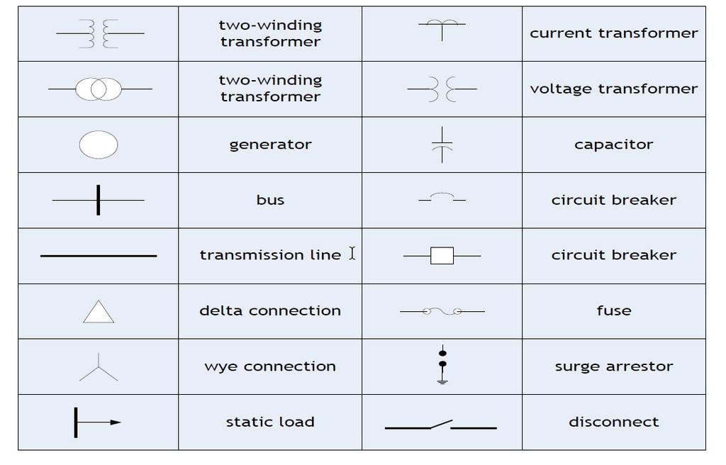
7 PROTECTION SYMBOL
8 PRIMARY EQUIPMENT & COMPONENTS Transformers-to step up or step down voltage level. Breakers-to energize equipment and interrupt fault current to isolate faulted equipment. Insulators-to insulate equipment from ground and other phases. Isolators (switches) -to create a visible and permanent isolation of primary equipment for maintenance purposes and route power flow over certain buses. Bus-to allow multiple connections (feeders) to the same source of power (transformer).
9 PRIMARY EQUIPMENT & COMPONENTS Grounding-to operate and maintain equipment safely Arrester-to protect primary equipment of sudden overvoltage (lightning strike). Switchgear integrated components to switch, protect, meter and control power flow. Reactors-to limit fault current (series) or compensate for charge current (shunt). VT and CT -to measure primary current and voltage and supply scaled down values to P&C, metering, SCADA, etc. Regulators-voltage, current, VAR, phase angle, etc.
10 WHY A SYSTEM NEEDS PROTECTION? There is no fault free system. Ensure safety of personnel. Usually faults are caused by breakdown of insulation due to various reasons : system over current, over voltage, lighting etc.
11
12
13
14 POWER SYSTEM WITHOUT PROTECTION Short circuits and other abnormal conditions often occur on the power system. The heavy current associated with short circuits is likely to cause damage to the equipment.
15 ELEMENT OF PROTECTION SYSTEM (1) Current and Voltage Transformers. (2) Relays. (3) Circuit breakers. (4) Batteries. (5) Fuses. (6) Lighting Arresters.


16 CURRENT TRANSFORMER Current transformer consists at least of two secondary windings. The first winding is usually designed for measuring, the second is used for protection. The secondary of current transformers are almost connected in star

17 VOLTAGE TRANSFORMER Voltage transformer is often consists of two windings. The first winding is connected in star, and the stare point must be earthed. The second winding is connected as open delta.
18 PURPOSE OF RELAY Isolate controlling circuit from controlled circuit. Control high voltage system with low voltage. Control high current system with low current. Logic Functions
19 ADVANTAGES FOR USING PROTECTIVE RELAYS Detect system failures when they occur and isolate the faulted section from the remaining of the system. Mitigating the effects of failures after they occur. Minimize risk of fire, danger to personal and other high voltage systems.
20 CIRCUIT BREAKER Low voltage circuit breaker. Magnetic circuit breaker. Medium voltage circuit breaker. High voltage circuit breaker.
21 BATTERY BANK Battery bank are called as backbone of protection system. Emergency use for power system.
22 FUSE Fuses are selected to allow passage of normal current and of excessive current only for short periods. It is used to protect the low voltage or current rating devices.
23 LIGHTING ARRESTER A lightning arrester is a device used on electrical power system to protect the insulation damaging effect of lightning. All lighting arrester are earthed.
24 WHAT IS SWITCHGEAR? Switchgear is the combination of switches, fuses or circuit breakers(cb) used to control, protect & isolate electrical equipment. It is used de-energize equipment & clear faults.
25 DIFFERENT ELEMENTS OF SWITCHGEAR
26 FUNCTION WISE CATEGORIES Automatic & Manual operation { example: Circuit breaker,mcb, MCCB } Only automatic operation Fuse Only manually activated / operated Isolator, LBS
27 VOLTAGE WISE SWITCHGEAR CATEGORIES Low voltage Switchgear up to 11KV Medium voltage switchgear up to 66KV High Voltage switchgear up to 400KV Extra High Voltage switchgear up to 765KV HVDC Switch gear
28 QUALITATIVE REVIEW OF FAULTS & FAULT CURRENTS
29 NATURE & CAUSES OF FAULTS Insulation failure. Conducting path failure. Over voltages due to lightening or switching surges. Puncturing or breaking of insulators. Failure of conducting path due to broken conductors. Failure of solid insulation due to aging, heat, moisture, overvoltage, accidental contact with earth or earth screens, flash over voltages and etc.,
30 FAULT IN POWER SYSTEM A power system fault may be defined as any condition or abnormality of the system which involves the electrical failure of primary equipment such as generators, transformers, bus bars, overhead lines and cables and all other items of plant which operate at power system voltage. Electrical failure generally implies one or the other (or both) of two types of failure, namely insulation failure resulting in a short- circuit condition or conducting path failure resulting in an open-circuit condition, the former being by far the more common type of failure.
31 FAULT IN POWER SYSTEM Symmetrical fault Faults giving rise to equal currents in lines displaced by equal phase angles i.e120oin three phase systems. Example: short circuit of all three phase conductors of a cable at a single location Unsymmetrical fault Faults in which not all the line currents are equal and not all have the same phase. Example(any one): single phase line to ground fault (L-G), two phase to ground (LL-G) fault and phase to phase (L-L) fault.
32 ABNORMALITIES IN POWER SYSTEMS Overcurrent (overload, short circuit, open circuit) Ground Potential (ungrounded equipment, touch potentials, step potentials) Surge Voltages (lightning strokes, switching surges, harmonics)
33 FAULT TYPES (SHUNT)
34
35 FREQUENCY OF TYPES OF FAULTS Type of Fault SLG LL DLG 3L % Occurrence or less
36 FREQUENCY OF FAULT OCCURRENCE Equipment Overhead lines Cables Switch gear Transformers CTs and PTs Control Equipment Miscellaneous % 0f Total
37 SYMMETRICAL FAULT THREE-PHASE FAULT THREE PHASE -EARTH FAULT
38 UNSYMMETRICAL FAULT PHASE PHASE FAULT TWO PHASE EARTH FAULT SINGLE PHASE -EARTH FAULT
39 OPEN CIRCUIT FAULT SINGLE-PHASE OPEN CIRCUIT TWO-PHASE OPEN CIRCUIT THREE-PHASE OPEN CIRCUIT
 Alternator (7%) Causes of Faults Lighting Stroke Earthquake Icing")

40 Equipments & % of total fault Over head lines (50%) Under ground Cable (9%) Alternator (7%) Causes of Faults Lighting Stroke Earthquake Icing Birds Tree branches Kite Strings Internal Overvoltage Damage due to digging Insulation failure due to temperature rise Failure of Joints Stator & Rotor faults
 Switch Gear (12%) Overvoltage Insulation Failure Break of Conductors Wrong Connections Insulation failure Leakage of air/oil/gas")
41 Equipments & % of total fault Causes of Faults Transformer (10%) Insulation Failure Faults in tap changer Overloading Current Transformer & Potential Transformer (12%) Switch Gear (12%) Overvoltage Insulation Failure Break of Conductors Wrong Connections Insulation failure Leakage of air/oil/gas Mechanical defect
42
43 FAULT MINIMIZATION Improving the quality of machines, equipments, installation etc., by improving the design techniques. Adequate & reliable protection system control. Regular maintenance by trained professionals. Effective management of electrical plant.
44 MERITS OF FAST FAULT CLEARING Helps to avoid permanent damage to equipment & components of the apparatus. Reduces the chances of risks like fire hazards. Maintains the continuity of the power supply. Brings back the power system to the normal state sooner.
45 RELAY TERMINOLOGY DEFINITIONS

46 WHAT ARE RELAYS? Relays are electrical switches that open or close another circuit under certain conditions.
47 WHAT IS A PROTECTIVE RELAY? Protective relays are devices which monitor power system conditions and operate to quickly and accurately isolate faults or dangerous conditions. A well designed protective system can limit damage to equipment, as well as minimize the extent of associated service interruption.
48 RELAY PURPOSE Isolate controlling circuit from controlled circuit. Control high voltage system with low voltage. Control high current system with low current. Logic Functions.
49 RELAY TYPES Electromagnetic Relays (EMRs) Solid-state Relays (SSRs) There is no mechanical contacts to switch the circuit. Microprocessor Based Relays Commonly used in power system monitoring and protection.
50 ADVANTAGES / DISADVANTAGES Electromagnetic Relays (EMRs) Simplicity Not expensive Solid-state Relays (SSRs) No Mechanical movements Faster than EMR Microprocessor-based Relay Much higher precision and more reliable and durable. Capable of both digital and analog I/O. Higher cost
51 ADVANTAGES FOR USING PROTECTIVE RELAYS Detect system failures when they occur and isolate the faulted section from the remaining of the system. Mitigating the effects of failures after they occur. Minimize risk of fire, danger to personal and other high voltage systems.

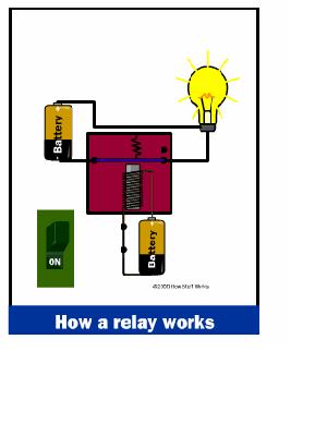
52 HOW A RELAY WORKS?

53 COMPONENTS OF POWER SYSTEM PROTECTION
54 Primary Relay : relay connected directly in the circuit. Secondary Relay : relay connected to the protected circuit through CT & VT. Auxiliary Relay : relay operate in response to opening or closing of another relay. Measuring Relay : It performs the measurement of normal & abnormal conditions in the power system. Electro Magnetic Relay : It operates on the principle of Electro magnetic induction. Static Relay (Solid-state relay) : They use diode, transistors, SCRs, Logic gates etc. (Static circuit is the measuring circuit & no moving parts) Microprocessor Based Relay : All functions of a relay can done by using microprocessor. Relays are
55 Thermal Relay : It operates on the principle of Electro-thermal effect. Distance Relay : relay measures the impedance or reactance or admittance. Impedance Relay transmission line. : relay measures the impedance of the Reactance Relay transmission line. : relay measures the reactance of the Over-current Relay : relay operates when the current exceeds a pre-set value. Under-voltage Relay : relay operates when the voltage falls a pre-set value. Directional Relay : relay able to sense whether forward or reverse direction. fault lies in Polarized Relay : relay depends on the direction of the current.
56 Differential Relay: it measures the difference b/w 2 actual quantities. Earth fault Relay: It is used for protection of element of a power system against Earth faults. Phase fault Relay: It is used for protection of element of a power system against phase faults. Negative Sequence Relay: relay uses negative sequence current as its actuating quantity. Zero Sequence Relay: relay uses zero sequence current as its actuating quantity.
57 ESSENTIAL QUALITIES OF PROTECTION OR REQUIREMENT OF PROTECTIVE SYSTEM
58 Reliability - assurance that the protection will perform correctly. Selectivity - maximum continuity of service with minimum system disconnection. Sensitivity - To detect even the smallest fault, current or system abnormalities and operate correctly at its setting. Speed - minimum fault duration and consequent equipment damage and system instability. Simplicity - minimum protective equipment and associated circuitry to achieve the protection objectives.
59 Reliability othe level of assurance that the relay will function as intended. oreliability denotes : Dependability-certainty of correct operation Security-assurance against incorrect operation Sensitivity orelaying equipment must be sufficiently sensitive so that it will operate when required omust discriminate normal from abnormal conditions.
60 Selectivity o Performance of protective devices to select between those conditions for which prompt operation and those for which no o o Speed o o operation, or time delay operation is required. Isolate faulted circuit resulting in minimum interruptions. Implemented through Zone of Protection Remove a fault from the power system as quickly as possible Classification: Instantaneous -no intentional delay High Speed -less than 3 cycles Time-Delay -intentional time delay
61 POWER SYSTEM EARTHING Neutral Earthing /Grounding Peterson coil Arcing Grounds
62 EARTHING / GROUNDING The process of connecting the metallic frame (i.e. non-current carrying part) of electrical equipment or some electrical part of the system to earth (i.e. soil) is called grounding or earthing. Grounding or earthing may be classified as: (i) Equipment grounding (ii) System grounding
63 GROUNDING TYPES Equipment Grounding The process of connecting noncurrent-carrying metal parts of the electrical equipment to earth. System Grounding The process of connecting some electrical part of the power system to earth (i.e.soil) is called system grounding.
64 NEUTRAL EARTHING
65 NEUTRAL GROUNDING Connecting neutral point to earth (i.e.soil) either directly or some circuit element (e.g.resistance, reactance, Peterson coil etc.) is called neutral grounding. Neutral grounding provides protection to equipment. (during earth fault, the current path is completed neutral)
66 ADVANTAGES OF NEUTRAL GROUNDING (i) Voltages of the healthy phases do not exceed line to ground voltages i.e. they remain nearly constant. (ii) The high voltages due to arcing grounds are eliminated. (iii) Life of insulation is long. (iv) The over voltages is reduced. (v) It provides greater safety to personnel and equipment. (vi) It provides improved service reliability. (vii) Operating and maintenance expenditures are reduced.
67 METHODS OF NEUTRAL GROUNDING 1. Solid or effective grounding 2. Resistance grounding 3. Reactance grounding 4. Peterson-coil grounding 5. Voltage transformer earthing

68 1. SOLID OR EFFECTIVE GROUNDING
69 1. SOLID OR EFFECTIVE GROUNDING When the neutral point of a 3-phase system is directly connected to earth(i.e. soil) is called solid grounding or effective grounding. When an earth fault occurs between earth and any one phase, the voltage to earth of the faulty phase becomes zero, but the healthy phases remains at normal phase values. Fault current(if) completely nullified by capacitive current(ic)
 is connected to earth ( i.e. soil) through a resistor, it is called resistance grounding.")
70 2. RESISTANCE GROUNDING When the neutral point of a 3-phase system (e.g. 3-phase generator, 3-phase transformer etc.) is connected to earth ( i.e. soil) through a resistor, it is called resistance grounding.
71 2. RESISTANCE GROUNDING Advantages: By adjusting the value of R, the arcing grounds can be minimized. It improves the stability. Less interference. Minimize hazards. Disadvantages: By adjusting the value of R, the arcing grounds can be minimized. It improves the stability. Less interference. Minimize hazards.
 In this system, the fault current required to operate the protective device is higher than that of resistance grounding for the same fault conditions.")
72 3. REACTANCE GROUNDING In this system, a reactance is inserted between the neutral and ground. The purpose of reactance is to limit the earth fault current. Disadvantages: (i) In this system, the fault current required to operate the protective device is higher than that of resistance grounding for the same fault conditions. (ii) High transient voltages appear under fault conditions.
73 4. PETERSON COIL (OR) ARC SUSPENSION COIL GROUNDING (OR) RESONANT GROUNDING
74 4. PETERSON COIL GROUNDING If inductance L of appropriate value is connected in parallel with the capacitance of the system, the fault current IF flowing through L will be in phase opposition to the capacitive current IC of the system. If L is so adjusted that IL = IC then resultant current in the fault will be zero. This condition is known as Resonant Grounding. When the value of L of arc suppression coil is such that the fault current IF exactly balances the capacitive current IC, it is called Resonant Grounding.

75 4. PETERSON COIL GROUNDING An arc suppression coil (also called Peterson coil) is an ironcored coil connected between the neutral and earth. The reactor is provided with tappings to change the inductance of the coil. By adjusting the tappings on the coil, the coil can be tuned with the capacitance of the system i.e. resonant grounding can be achieved.
76 4. PETERSON COIL GROUNDING Suppose line to ground fault occurs in the line B at point F. The fault current IF and capacitive currents IR and IY will flow as shown in Fig Note that IF flows through the Peterson coil (or Arc suppression coil) to neutral and back through the fault. The total capacitive current IC is the phasor sum of IR & IY as shown in phasor diagram in Fig. The voltage of the faulty phase is applied across the arc suppression coil. Therefore, fault current IF lags the faulty phase voltage by 90. The current IF is in phase opposition to capacitive current IC [SeeFig]. By adjusting the tappings on the Peterson coil, the resultant current in the fault can be reduced. If inductance of the coil is so adjusted that IL =
77 4. PETERSON COIL GROUNDING

78 4. PETERSON COIL GROUNDING
79 5. VOLTAGE TRANSFORMER EARTHING In this method of neutral earthing, the primary of a single-phase voltage transformer is connected between the neutral and the earth as shown in Fig A low resistor in series with a relay is connected across the secondary of the voltage transformer. The voltage transformer provides a high reactance in the neutral earthing circuit and operates virtually as an ungrounded neutral system.

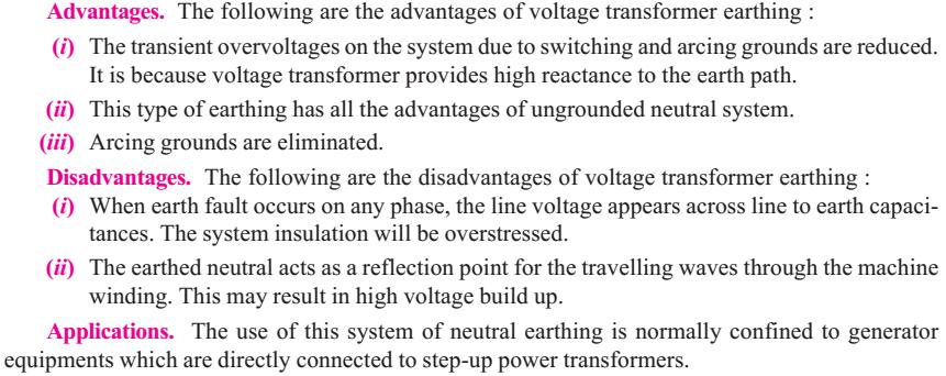
80 5. VOLTAGE TRANSFORMER EARTHING
81 PROTECTION AGAINST OVER VOLTAGES DUE TO LIGHTNING AND SWITCHING
82 PROTECTION AGAINST OVER VOLTAGES DUE TO LIGHTNING AND SWITCHING During Operation, PS equipments such as Generator, transformer, Tx. lines may subject to Over Voltage. OV occurs due to Lightning, opening of CB & so on. Causes Of OV Internal Cause External Cause
83 PROTECTION AGAINST OVER VOLTAGES DUE TO LIGHTNING AND SWITCHING External Lightning Tree falls on Tx.lines causes SC Internal Insulation Failure Resonance Arching Ground Switching Surges
84 TYPES OF OVER VOLTAGES Power Frequency OV Switching OV Lightning OV
85 1. POWER FREQUENCY OV Does not have damaging effects like switching or lightning surges It will be harmful, if sustained for longer duration Mainly due to Ground faults Sudden load rejection Loose connection
86 2. SWITCHING OV Also known as Switching surge or over voltage transient. Sudden rise of voltage for a very short duration in PS network is known as transient voltage or voltage surge. An electrical transient appears, if there is sudden change in the state of energy in PS network. This sudden change is due to i. Closing a Switch ii. Opening a Switch iii. Occurrence of fault in system To control the switching OV, Resistor is inserted between the contacts while switching off the circuit.
87 3. LIGHTNING OV Lightning is an electric discharge between cloud & Earth or between clouds. It is basically a huge spark. A large number of discharge occurs between or with in clouds than to earth & enough of them terminate on the earth causing serious hazards. Following actions of the lightning stroke generate transients: * Direct Stroke to Phase Conductor * Stroke to earth very close to line

88 SURGE DIVERTER
89 WHAT IS SURGE? Surges disturbances on a power waveform that can damage, or destroy equipment within any home, commercial building, or manufacturing facility. Surges are measured in microseconds.
90 SURGE DIVERTERS A surge diverter is a piece of equipment that diverts excess voltages to earth, thus protecting sensitive electrical and electronic equipment. The surge diverter is normally installed in the main switchboard.
91 REQUIREMENT OF SURGE DIVERTER It should not pass any current at normal and abnormal power frequency voltage. It should breakdown as quickly as possible after the abnormal high frequency voltage arrives. It should not only protect the equipment for which it is used but should discharge current without damaging itself. It should interrupt power frequency follow current after the surge is discharge to ground.
92 TYPES OF SURGE DIVERTERS Rod gap type surge diverter. Protector tube or expulsion type surge diverter. Valve type surge diverter.
93 1. ROD GAP TYPE SURGE DIVERTER It is a very simple type of diverter and consists of two 1.5 cm rods. One rod is connected to the line circuit and the other rod is connected to earth. The distance between gap and insulator must not be less than one third of the gap length so that the arc may not reach the insulator and damage it. The rod gap should be so set that it breaks down to a voltage not less than 30% below the voltage withstand level of the equipment to be protected.
94 ROD GAP TYPE SURGE DIVERTER
95 ROD GAP TYPE SURGE DIVERTER The string of insulators for an overhead line on the bushing of transformer has frequently a rod gap across it. Under normal operating conditions, the gap remains non-conducting. On the occurrence of a high voltage surge on the line, the gap sparks over and the surge current is conducted to earth. In this way excess charge on the line due to the surge is harmlessly conducted to earth.
96 ROD GAP TYPE SURGE DIVERTER Limitations : After the surge is over, the arc in the gap is maintained by the normal supply voltage, leading to short-circuit on the system. The rods may melt or get damaged due to excessive heat produced by the arc. The climatic conditions (e.g. rain, humidity, temperature etc.) affect the performance of rod gap arrester. The polarity of the surge also affects the performance of this arrester.
97 2. EXPULSION TYPE SURGE DIVERTER This type of arrester is also called protector tube and is commonly used on system operating at voltages up to 33kV. It essentially consists of a rod gap in series with a second gap enclosed within the fiber tube. The gap in the fiber tube is formed by two electrodes. The upper electrode is connected to rod gap and the lower electrode to the earth.
98 EXPULSION TYPE SURGE DIVERTER
99 EXPULSION TYPE SURGE DIVERTER The series gap is set to arc over at a specified voltage lower than the withstand voltage of the equipment to be protected. The follow-on current is confined to the space inside the relatively small fibre tube. Part of the tube material vaporizes, and the high pressure gases so formed are expelled through the vent at the lower end of the tube, causing the power follow-in arc to be extinguished. The device, therefore, has the desired self-clearing property.
100 EXPULSION TYPE SURGE DIVERTER Advantages They are not very expensive. They can be easily installed. They are improved form of rod gap arresters as they block the flow of power frequency follow currents.
101 EXPULSION TYPE SURGE DIVERTER Limitations An expulsion type arrester can perform only limited number of operations as during each operation some of the fiber material is used up. This type of arrester cannot be mounted on enclosed equipment due to discharge of gases during operation. Due to the poor volt/amp characteristic of the arrester, it is not suitable for protection of expensive equipment.
102 3. VALVE TYPE SURGE DIVERTER Valve type arresters incorporate non linear resistors and are extensively used on systems, operating at high voltages. It consists of two assemblies (i) series spark gaps and (ii) non-linear resistor discs The non-linear elements are connected in series with the spark gaps. Both the assemblies are accommodated in tight porcelain container. The spark gap is a multiple assembly consisting of a number of identical spark gaps in series. Each gap consists of two electrodes with fixed gap spacing.
103 VALVE TYPE SURGE DIVERTER The spacing of the series gaps is such that it will withstand the normal circuit voltage. An over voltage will cause the gap to break down causing the surge current to ground via the non-linear resistors. The non-linear resistor discs are made of inorganic compound such as thyrite or metrosil. These discs are connected in series. The non-linear resistors have the property of offering a high resistance to current flow when normal system voltage is applied, but a low resistance to the flow of high surge currents.
104 VALVE TYPE SURGE DIVERTER When the surge is over the non linear resistor assume high resistance to stop the flow of current.
105 VALVE TYPE SURGE DIVERTER Under normal conditions, the normal system voltage is insufficient to cause the breakdown of air gap assembly. On the occurrence of an over voltage, the breakdown of the series spark gap takes place and the surge current is conducted to earth via the nonlinear resistances. Since the magnitude of surge current is very large, the nonlinear elements will offer a very low resistance to the passage of surge. The surge will rapidly go to earth instead of being sent back over the line.
106 VALVE TYPE SURGE DIVERTER ADVANTAGES : They provide very effective protection against surges. They operate very rapidly taking less than a second The impulse ratio is practically unity.
107 VALVE TYPE SURGE DIVERTER Limitations : They may fail to check the surge of very steep wave front reaching the terminal apparatus. This calls for additional steps to check steep fronted waves. Their performance is adversely affected by the entry of moisture into the enclosure. This necessitates effective sealing of the enclosure at all times.
108 SURGE ABSORBER
109 SURGE ABSORBER The Device which reduces the steepness of the wave front of a particular surge & thus minimizes the danger due to over voltage is known as surge absorber. Note: Surge Diverter : Diverts the Surge to earth Surge Absorber : Absorbs the Surge energy
110 TYPES OF SURGE ABSORBER Ferranti Surge absorber ERA Surge absorber

111 FERRANTI SURGE ABSORBER It consists of an air core inductor connected Series inline & surrounded Dissipater Air cored inductor by an earth metallic sheet (ie) dissipater. Whenever a travelling wave is incident on the surge absorber, energy is transformed by mutual inductance between coil & dissipater. ie., the energy contained in the wave is dissipated in the form of heat. Because of the series inductance the steepness of the wave is also reduced.

112 ERA SURGE ABSORBER Improved form of Surge absorber is the Electrical Research Association type surge filter. G Gap ; E Expulsion gap When a wave reaches the L, a high voltage is induced across it causing the gap G to break down putting the R and E in to circuit. Thus incoming wave get flattened by L & R and its amplitude is reduced by E.
113 BASIC IDEAS OF INSULATION CO- ORDINATION
114 INSULATION COORDINATION Correlating (link) apparatus insulation with insulation of the protective device to achieve overall protection is known as insulation coordination. The insulation strength of various equipments should be higher than that of lightning arresters and other surge protective devices.
115 INSULATION COORDINATION In its simplest form, Insulation Coordination is the selection of insulation strength. Characteristics of lightning arrestor should be correlated with equipment isolation
116 INSULATION COORDINATION The insulation of the line lightning arrestor & equipment should be coordinated. Curve A relates to Protective device Curve B equipment to be protected Protective device must have insulation characteristics which must be lie below the insulation characteristics of instrument to be protected.
117 INSULATION COORDINATION A perfect insulation coordination must satisfy the following conditions: The insulation should withstand both operating voltage & voltage surges. The discharge of OV due to internal or external causes must flow to ground efficiently. Only external flashover should cause breakdown.
118 BASIC IMPULSE INSULATION LEVEL (BIL) It is defined as a reference level expressed in impulse crest voltage with a standard wave not longer than 1.5*40 micro seconds wave.
119 THANK YOU
2 Grounding of power supply system neutral
 2 Grounding of power supply system neutral 2.1 Introduction As we had seen in the previous chapter, grounding of supply system neutral fulfills two important functions. 1. It provides a reference for the
CONTENTS. 1. Introduction Generating Stations 9 40
 CONTENTS 1. Introduction 1 8 Importance of Electrical Energy Generation of Electrical Energy Sources of Energy Comparison of Energy Sources Units of Energy Relationship among Energy Units Efficiency Calorific
Protection Basics Presented by John S. Levine, P.E. Levine Lectronics and Lectric, Inc GE Consumer & Industrial Multilin
 Protection Basics Presented by John S. Levine, P.E. Levine Lectronics and Lectric, Inc. 770 565-1556 John@L-3.com 1 Protection Fundamentals By John Levine 2 Introductions Tools Outline Enervista Launchpad
Power systems Protection course
 Al-Balqa Applied University Power systems Protection course Department of Electrical Energy Engineering 1 Part 5 Relays 2 3 Relay Is a device which receive a signal from the power system thought CT and
Busbars and lines are important elements
 CHAPTER CHAPTER 23 Protection of Busbars and Lines 23.1 Busbar Protection 23.2 Protection of Lines 23.3 Time-Graded Overcurrent Protection 23.4 Differential Pilot-Wire Protection 23.5 Distance Protection
EE 1402 HIGH VOLTAGE ENGINEERING
 EE 1402 HIGH VOLTAGE ENGINEERING Unit 5 TESTS OF INSULATORS Type Test To Check The Design Features Routine Test To Check The Quality Of The Individual Test Piece. High Voltage Tests Include (i) Power frequency
Numbering System for Protective Devices, Control and Indication Devices for Power Systems
 Appendix C Numbering System for Protective Devices, Control and Indication Devices for Power Systems C.1 APPLICATION OF PROTECTIVE RELAYS, CONTROL AND ALARM DEVICES FOR POWER SYSTEM CIRCUITS The requirements
ROEVER ENGINEERING COLLEGE ELAMBALUR, PERAMBALUR DEPARTMENT OF ELECTRICAL & ELECTRONICS ENGINEERING
 ROEVER ENGINEERING COLLEGE ELAMBALUR, PERAMBALUR 621 212 DEPARTMENT OF ELECTRICAL & ELECTRONICS ENGINEERING EE1003 HIGH VOLTAGE ENGINEERING QUESTION BANK UNIT-I OVER VOLTAGES IN ELECTRICAL POWER SYSTEM
Condition Assessment of High Voltage Insulation in Power System Equipment. R.E. James and Q. Su. The Institution of Engineering and Technology
 Condition Assessment of High Voltage Insulation in Power System Equipment R.E. James and Q. Su The Institution of Engineering and Technology Contents Preface xi 1 Introduction 1 1.1 Interconnection of
Unit 3 Magnetism...21 Introduction The Natural Magnet Magnetic Polarities Magnetic Compass...21
 Chapter 1 Electrical Fundamentals Unit 1 Matter...3 Introduction...3 1.1 Matter...3 1.2 Atomic Theory...3 1.3 Law of Electrical Charges...4 1.4 Law of Atomic Charges...4 Negative Atomic Charge...4 Positive
Preface...x Chapter 1 Electrical Fundamentals
 Preface...x Chapter 1 Electrical Fundamentals Unit 1 Matter...3 Introduction...3 1.1 Matter...3 1.2 Atomic Theory...3 1.3 Law of Electrical Charges...4 1.4 Law of Atomic Charges...5 Negative Atomic Charge...5
FERRORESONANCE SIMULATION STUDIES USING EMTP
 FERRORESONANCE SIMULATION STUDIES USING EMTP Jaya Bharati, R. S. Gorayan Department of Electrical Engineering Institute of Technology, BHU Varanasi, India jbharatiele@gmail.com, rsgorayan.eee@itbhu.ac.in
10. DISTURBANCE VOLTAGE WITHSTAND CAPABILITY
 9. INTRODUCTION Control Cabling The protection and control equipment in power plants and substations is influenced by various of environmental conditions. One of the most significant environmental factor
FGJTCFWP"KPUVKVWVG"QH"VGEJPQNQI[" FGRCTVOGPV"QH"GNGEVTKECN"GPIKPGGTKPI" VGG"246"JKIJ"XQNVCIG"GPIKPGGTKPI
 FGJTFWP"KPUKWG"QH"GEJPQNQI[" FGRTOGP"QH"GNGETKEN"GPIKPGGTKPI" GG"46"JKIJ"XQNIG"GPIKPGGTKPI Resonant Transformers: The fig. (b) shows the equivalent circuit of a high voltage testing transformer (shown
Industrial Electrician Level 3
 Industrial Electrician Level 3 Industrial Electrician Unit: C1 Industrial Electrical Code I Level: Three Duration: 77 hours Theory: Practical: 77 hours 0 hours Overview: This unit is designed to provide
Webinar: An Effective Arc Flash Safety Program
 Webinar: An Effective Arc Flash Safety Program Daleep Mohla September 10 th, 2015: 2pm ET Agenda Arc Flash Defined and Quantified NFPA 70E / CSA Z 462 - Recent Updates What is the ANSI Z10 Hierarchy of
Specialists in HV and MV test and diagnostics. Testing in Substations
 Specialists in HV and MV test and diagnostics Testing in Substations Testing in Substations Testing in Substations At 4fores we specialize in the diagnosis and measurement of all types of existing technologies
Earth Fault Protection
 Earth Fault Protection Course No: E03-038 Credit: 3 PDH Velimir Lackovic, Char. Eng. Continuing Education and Development, Inc. 9 Greyridge Farm Court Stony Point, NY 10980 P: (877) 322-5800 F: (877) 322-4774
A DUMMIES GUIDE TO GROUND FAULT PROTECTION
 A DUMMIES GUIDE TO GROUND FAULT PROTECTION A DUMMIES GUIDE TO GROUND FAULT PROTECTION What is Grounding? The term grounding is commonly used in the electrical industry to mean both equipment grounding
R10. IV B.Tech I Semester Regular/Supplementary Examinations, Nov/Dec SWITCH GEAR AND PROTECTION. (Electrical and Electronics Engineering)
") R10 Set No. 1 Code No: R41023 1. a) Explain how arc is initiated and sustained in a circuit breaker when the CB controls separates. b) The following data refers to a 3-phase, 50 Hz generator: emf between
R10 Set No. 1 Code No: R41023 1. a) Explain how arc is initiated and sustained in a circuit breaker when the CB controls separates. b) The following data refers to a 3-phase, 50 Hz generator: emf between
COOPERATIVE PATENT CLASSIFICATION
 CPC H H02 COOPERATIVE PATENT CLASSIFICATION ELECTRICITY (NOTE omitted) GENERATION; CONVERSION OR DISTRIBUTION OF ELECTRIC POWER EMERGENCY PROTECTIVE CIRCUIT ARRANGEMENTS (indicating or signalling undesired
Upgrading Your Electrical Distribution System To Resistance Grounding
 Upgrading Your Electrical Distribution System To Resistance Grounding The term grounding is commonly used in the electrical industry to mean both equipment grounding and system grounding. Equipment grounding
DEPARTMENT OF ELECTRICAL AND ELECTRONICS ENGINEERING QUESTION BANK SUBJECT CODE & NAME : EE 1402 HIGH VOLTAGE ENGINEERING UNIT I
 DEPARTMENT OF ELECTRICAL AND ELECTRONICS ENGINEERING QUESTION BANK SUBJECT CODE & NAME : EE 1402 HIGH VOLTAGE ENGINEERING YEAR / SEM : IV / VII UNIT I OVER VOLTAGES IN ELECTRICAL POWER SYSTEMS 1. What
Grounding System Theory and Practice
 Grounding System Theory and Practice Course No. E-3046 Credit: 3 PDH Grounding System Theory and Practice Velimir Lackovic, Electrical Engineer System grounding has been used since electrical power systems
Transformer Protection
 Transformer Protection Nature of transformer faults TXs, being static, totally enclosed and oil immersed develop faults only rarely but consequences large. Three main classes of faults. 1) Faults in Auxiliary
Section 6: System Grounding Bill Brown, P.E., Square D Engineering Services
 Section 6: System Grounding Bill Brown, P.E., Square D Engineering Services Introduction The topic of system grounding is extremely important, as it affects the susceptibility of the system to voltage
Modern transformer relays include a comprehensive set of protective elements to protect transformers from faults and abnormal operating conditions
 1 Transmission transformers are important links in the bulk power system. They allow transfer of power from generation centers, up to the high-voltage grid, and to bulk electric substations for distribution
# - - Internal * On Line Examination
 COURSE NAME : ELECTRICAL ENGINEERING GROUP COURSE CODE : EE/EP SEMESTER : FIFTH SUBJECT TITLE : SWITCHGEAR and PROTECTION SUBJECT CODE : Teaching and Examination Scheme: Teaching Scheme TH TU PR PAPER
Electrical Power Systems
 Electrical Power Systems CONCEPT, THEORY AND PRACTICE SECOND EDITION SUBIR RAY Professor MVJ College of Engineering Bangalore PHI Learning Pfcte tofm Delhi-110092 2014 Preface xv Preface to the First Edition
Relay Types and Applications Dr. Sasidharan Sreedharan
 O&M of Protection System and Relay Coordination Relay Types and Applications Dr. Sasidharan Sreedharan www.sasidharan.webs.com Detailed Schedule 2 SIMPLE RELAY Magnitude Rate of Change Phase Angle Direction
Sequence Networks p. 26 Sequence Network Connections and Voltages p. 27 Network Connections for Fault and General Unbalances p. 28 Sequence Network
 Preface p. iii Introduction and General Philosophies p. 1 Introduction p. 1 Classification of Relays p. 1 Analog/Digital/Numerical p. 2 Protective Relaying Systems and Their Design p. 2 Design Criteria
HIGH VOLTAGE ENGINEERING(FEEE6402) LECTURER-24
 LECTURER-24") LECTURER-24 GENERATION OF HIGH ALTERNATING VOLTAGES When test voltage requirements are less than about 300kV, a single transformer can be used for test purposes. The impedance of the transformer should
LECTURER-24 GENERATION OF HIGH ALTERNATING VOLTAGES When test voltage requirements are less than about 300kV, a single transformer can be used for test purposes. The impedance of the transformer should
Overview of Grounding for Industrial and Commercial Power Systems Presented By Robert Schuerger, P.E.
 Overview of Grounding for Industrial and Commercial Power Systems Presented By Robert Schuerger, P.E. HP Critical Facility Services delivered by EYP MCF What is VOLTAGE? Difference of Electric Potential
3. (a) List out the advantages and disadvantages of HRC fuse (b) Explain fuse Characteristics in detail. [8+8]
![3. (a) List out the advantages and disadvantages of HRC fuse (b) Explain fuse Characteristics in detail. [8+8]](/thumbs/77/76027701.jpg "3. (a) List out the advantages and disadvantages of HRC fuse (b) Explain fuse Characteristics in detail. [8+8]") Code No: RR320205 Set No. 1 1. (a) Explain about Bewley s Lattice diagrams and also mention the uses of these diagrams. [6+2] (b) A line of surge impedance of 400 ohms is charged from a battery of constant
Code No: RR320205 Set No. 1 1. (a) Explain about Bewley s Lattice diagrams and also mention the uses of these diagrams. [6+2] (b) A line of surge impedance of 400 ohms is charged from a battery of constant
PIPSPC. Prepared by Eng: Ahmed Safie Eldin. And. Introduction. Protection Control. Practical. System. Power
 PIPSPC Practical Introduction Power System Protection Control Practical Introduction To Power System Protection And Control Prepared by Eng: Ahmed Safie Eldin 2005 Contents POWER SYSTEMS PRINCIPALS. 1
Neutral Reactor Optimization in order to Reduce Arc Extinction Time during Three-Phase Tripping
 Neutral Reactor Optimization in order to Reduce Arc Extinction Time during Three-Phase Tripping P. Mestas, M. C. Tavares Abstract. The optimization of the grounding neutral reactor is a common practice
High voltage engineering
 High voltage engineering Overvoltages power frequency switching surges lightning surges Overvoltage protection earth wires spark gaps surge arresters Insulation coordination Overvoltages power frequency
Earthing of Electrical Devices and Safety
 Earthing of Electrical Devices and Safety JOŽE PIHLER Faculty of Electrical Engineering and Computer Sciences University of Maribor Smetanova 17, 2000 Maribor SLOVENIA joze.pihler@um.si Abstract: - This
Education & Training
 Distribution System Operator Certificate This program provides you with a proficient working knowledge in modern electric power distribution systems. These four classes are designed to walk students through
1% Switchgear and Substations
 1% Switchgear and Substations Switchgear and substations are not always matters of concern for transmitter designers, -because they are often part of the facilities of a typical installation. However,
TECHNICAL BULLETIN 004a Ferroresonance
 May 29, 2002 TECHNICAL BULLETIN 004a Ferroresonance Abstract - This paper describes the phenomenon of ferroresonance, the conditions under which it may appear in electric power systems, and some techniques
PANIMALAR ENGINEERING COLLEGE Department of Electrical and Electronics Engineering
 PANIMALAR ENGINEERING COLLEGE Department of Electrical and Electronics Engineering 1. Write some applications of high voltage? High Voltage Engineering 2 mark Question with answers Unit I Overvoltages
SCHEME OF COURSE WORK ( ) Electrical & Electronics Engineering. Electrical machines-i, II and power transmission engineering
 Electrical & Electronics Engineering. Electrical machines-i, II and power transmission engineering") SCHEME OF COURSE WORK (2015-2016) COURSE DETAILS: Course Title Course Code Program Branch Semester Prerequisites Course to which it is prerequisite Switchgear and Protection 15EE1116 B.Tech Electrical
SCHEME OF COURSE WORK (2015-2016) COURSE DETAILS: Course Title Course Code Program Branch Semester Prerequisites Course to which it is prerequisite Switchgear and Protection 15EE1116 B.Tech Electrical
thepower to protect the power to protect i-gard LITERATURE Low and medium voltage
 thepower to protect i-gard LITERATURE Low and medium voltage distribution systems Arc Flash Hazards and High Resistance Grounding Grounding of Standby and Emergency Power Systems Neutral Grounding Resistors
Tab 2 Voltage Stresses Switching Transients
 Tab 2 Voltage Stresses Switching Transients Distribution System Engineering Course Unit 10 2017 Industry, Inc. All rights reserved. Transient Overvoltages Decay with time, usually within one or two cycles
COPYRIGHTED MATERIAL. Index
 Index Note: Bold italic type refers to entries in the Table of Contents, refers to a Standard Title and Reference number and # refers to a specific standard within the buff book 91, 40, 48* 100, 8, 22*,
POWER FACTOR CORRECTION. HARMONIC FILTERING. MEDIUM AND HIGH VOLTAGE SOLUTIONS.
 POWER FACTOR CORRECTION. HARMONIC FILTERING. MEDIUM AND HIGH VOLTAGE SOLUTIONS. This document may be subject to changes. Contact ARTECHE to confirm the characteristics and availability of the products
Protection of Electrical Networks. Christophe Prévé
 Protection of Electrical Networks Christophe Prévé This Page Intentionally Left Blank Protection of Electrical Networks This Page Intentionally Left Blank Protection of Electrical Networks Christophe Prévé
ELECTRICAL POWER ENGINEERING
 Introduction This trainer has been designed to provide students with a fully comprehensive knowledge in Electrical Power Engineering systems. The trainer is composed of a set of modules for the simulation
ARC FLASH HAZARD ANALYSIS AND MITIGATION
 ARC FLASH HAZARD ANALYSIS AND MITIGATION J.C. Das IEEE PRESS SERIES 0N POWER ENGINEERING Mohamed E. El-Hawary, Series Editor IEEE IEEE PRESS WILEY A JOHN WILEY & SONS, INC., PUBLICATION CONTENTS Foreword
SAFETY ASPECTS AND NOVEL TECHNICAL SOLUTIONS FOR EARTH FAULT MANAGEMENT IN MV ELECTRICITY DISTRIBUTION NETWORKS
 SAFETY ASPECTS AND NOVEL TECHNICAL SOLUTIONS FOR EARTH FAULT MANAGEMENT IN MV ELECTRICITY DISTRIBUTION NETWORKS A. Nikander*, P. Järventausta* *Tampere University of Technology, Finland, ari.nikander@tut.fi,
Insulation Co-ordination For HVDC Station
 Insulation Co-ordination For HVDC Station Insulation Co-ordination Definitions As per IEC 60071 Insulation Coordination is defined as selection of dielectric strength of equipment in relation to the operating
Electrical Protection System Design and Operation
 ELEC9713 Industrial and Commercial Power Systems Electrical Protection System Design and Operation 1. Function of Electrical Protection Systems The three primary aims of overcurrent electrical protection
Utility System Lightning Protection
 Utility System Lightning Protection Many power quality problems stem from lightning. Not only can the high-voltage impulses damage load equipment, but the temporary fault that follows a lightning strike
HIGH VOLTAGE Insulation Coordination
 HIGH VOLTAGE Insulation Coordination Assistant Professor Suna BOLAT KRÖGER Eastern Mediterranean University Department of Electric & Electronic Engineering Insulation coordination The term Insulation Co-ordination
(2) New Standard IEEE P (3) Core : (4) Windings :
 New Standard IEEE P (3) Core : (4) Windings :") (d) Electrical characteristics (such as short-circuit withstand, commutating reactance, more number of windings, etc); (e) Longer life expectancy; (f) Energy efficiency; (g) more demanding environment.
(d) Electrical characteristics (such as short-circuit withstand, commutating reactance, more number of windings, etc); (e) Longer life expectancy; (f) Energy efficiency; (g) more demanding environment.
KNOW MORE ABOUT THE TRANSFORMERS. Glossary Transformers
 KNOW MORE ABOUT THE TRANSFORMERS Glossary Transformers Ambient temperature The existing temperature of the atmosphere surrounding a transformer installation. Ampere The practical unit of electric current.
Grounding for Power Quality
 Presents Grounding for Power Quality Grounding for Power Quality NEC 250.53 states that ground resistance should be less than 25 ohms. Is this true? Grounding for Power Quality No! NEC 250.53 states
ACS 1000 Transformer Failure Investigation. Nathan Schachter, Peng
 Investigation Nathan Schachter, Peng Objectives Learn what happened Explain why it happened Discuss solutions Suggest remedies so it does not happen again Prevention is the key to success 2 ACS 1000 VFD
Power Factor. Power Factor Correction.
 Power Factor. Power factor is the ratio between the KW and the KVA drawn by an electrical load where the KW is the actual load power and the KVA is the apparent load power. It is a measure of how effectively
Improving High Voltage Power System Performance. Using Arc Suppression Coils
 Improving High Voltage Power System Performance Using Arc Suppression Coils by Robert Thomas Burgess B Com MIEAust CPEng RPEQ A Dissertation Submitted in Fulfilment of the Requirements for the degree of
Substation Preventive Maintenance
 Substation Preventive Maintenance PROVINCIAL ELECTRICITY AUTHORITY 1 Presentation Contents 1) A kind of substation 2) Electrical equipment details of AIS substation 3) Electrical equipment details of GIS
EE High Voltage Engineering UNIT IV - MEASUREMENT OF HIGH VOLTAGES AND HIGH CURRENTS PART-A 1. Mention the techniques used in impulse current
 EE6701 - High Voltage Engineering UNIT IV - MEASUREMENT OF HIGH VOLTAGES AND HIGH CURRENTS PART-A 1. Mention the techniques used in impulse current measurements. Hall generators, Faraday generators and
MAHALAKSHMI ENGINEERING COLLEGE
 MAHALAKSHMI ENGINEERING COLLEGE TIRUCHIRAPALLI 621213 QUESTION BANK -------------------------------------------------------------------------------------------------------------- Sub. Code : EE2353 Semester
ET 40 - Electrician Theory Examination Marking Schedule
 ET 40 - Electrician Theory Examination Marking Schedule Notes:1. means that the preceding statement/answer earns 1 mark. 2. This schedule sets out the accepted answers to the examination questions. A marker
Secondary Arresters. Figure 1. Type L secondary surge arrester rated 175 Vac, 125 Vdc.
 Surge Arresters Secondary Arresters and Protective Gaps Electrical Apparatus 235-10 GENERAL INFORMATION The necessity of providing surge arrester protection on low-voltage circuits is fundamentally the
High Voltage DC Transmission Prof. Dr. S. N. Singh Department of Electrical Engineering Indian Institute of Technology Kanpur
 High Voltage DC Transmission Prof. Dr. S. N. Singh Department of Electrical Engineering Indian Institute of Technology Kanpur Module No. # 01 Lecture No. # 03 So, in last two lectures, we saw the advantage
Wind Power Facility Technical Requirements CHANGE HISTORY
 CHANGE HISTORY DATE VERSION DETAIL CHANGED BY November 15, 2004 Page 2 of 24 TABLE OF CONTENTS LIST OF TABLES...5 LIST OF FIGURES...5 1.0 INTRODUCTION...6 1.1 Purpose of the Wind Power Facility Technical
Our Brands. Where we are?
 CATALOG 2019 Our Brands Aktif trade mark for Measuring, Protection, Automatic Meter Reading, Billing and Energy Management Software. by Aktif Aktif trade mark for Measuring, Protection, Control and Power
DEPARTMENT OF EEE QUESTION BANK
 DEPARTMENT OF EEE QUESTION BANK (As Per AUT 2008 REGULATION) SUB CODE: EE1004 SUB NAME: POWER SYSTEM TRANSIENTS YEAR : IV SEM : VIII PREPARED BY J.S. MEGAVATHI AP/EEE UNIT-I SWITCHING TRANSIENTS 1.What
Introduce system protection relays like underfrequency relays, rate of change of frequency relays, reverse - power flow
 Module 1 : Fundamentals of Power System Protection Lecture 3 : Protection Paradigms - System Protection Objectives In this lecture we will: Overview dynamics in power systems. Introduce system protection
IV/IV B.Tech (Regular) DEGREE EXAMINATION. Electrical &Electronics Engineering
 DEGREE EXAMINATION. Electrical &Electronics Engineering") Hall Ticket Number: 14EE704 November, 2017 Seventh Semester Time: Three Hours Answer Question No.1 compulsorily. Answer ONE question from each unit. IV/IV B.Tech (Regular) DEGREE EXAMINATION Electrical
Hall Ticket Number: 14EE704 November, 2017 Seventh Semester Time: Three Hours Answer Question No.1 compulsorily. Answer ONE question from each unit. IV/IV B.Tech (Regular) DEGREE EXAMINATION Electrical
Single Line Diagram of Substations
 Single Line Diagram of Substations Substations Electric power is produced at the power generating stations, which are generally located far away from the load centers. High voltage transmission lines are
SURGE ARRESTERS AND TESTING. Keith Hill Doble Engineering Company
 SURGE ARRESTERS AND TESTING Keith Hill Doble Engineering Company Surge arresters are often overlooked when performing Power Factor tests on transformers, breakers and other apparatus in a substation. Often
CHAPTER 15 GROUNDING REQUIREMENTS FOR ELECTRICAL EQUIPMENT
 CHAPTER 15 GROUNDING REQUIREMENTS FOR ELECTRICAL EQUIPMENT A. General In a hazardous location grounding of an electrical power system and bonding of enclosures of circuits and electrical equipment in the
Back to the Basics Current Transformer (CT) Testing
 Testing") Back to the Basics Current Transformer (CT) Testing As test equipment becomes more sophisticated with better features and accuracy, we risk turning our field personnel into test set operators instead of
Back to the Basics Current Transformer (CT) Testing As test equipment becomes more sophisticated with better features and accuracy, we risk turning our field personnel into test set operators instead of
Course No: 1 13 (3 Days) FAULT CURRENT CALCULATION & RELAY SETTING & RELAY CO-ORDINATION. Course Content
 FAULT CURRENT CALCULATION & RELAY SETTING & RELAY CO-ORDINATION. Course Content") Course No: 1 13 (3 Days) FAULT CURRENT CALCULATION & RELAY SETTING & RELAY CO-ORDINATION Sr. No. Course Content 1.0 Fault Current Calculations 1.1 Introduction to per unit and percentage impedance 1.2
Course No: 1 13 (3 Days) FAULT CURRENT CALCULATION & RELAY SETTING & RELAY CO-ORDINATION Sr. No. Course Content 1.0 Fault Current Calculations 1.1 Introduction to per unit and percentage impedance 1.2
UNIT II MEASUREMENT OF POWER & ENERGY
 UNIT II MEASUREMENT OF POWER & ENERGY Dynamometer type wattmeter works on a very simple principle which is stated as "when any current carrying conductor is placed inside a magnetic field, it experiences
7P Series - Surge Protection Device (SPD) Features 7P P P
 Features 7P P P") Features 7P.09.1.255.0100 7P.01.8.260.1025 7P.02.8.260.1025 SPD Type 1+2 Surge arrester range - single phase system / three phase system Surge arresters suitable in low-voltage applications in order to
Features 7P.09.1.255.0100 7P.01.8.260.1025 7P.02.8.260.1025 SPD Type 1+2 Surge arrester range - single phase system / three phase system Surge arresters suitable in low-voltage applications in order to
Power Frequency Withstand Voltage On-site testing of 400 kv GIS
 Power Frequency Withstand Voltage On-site testing of 400 kv GIS D. Anaraki Ardakani, A. Omidkhoda, M. Solati High Voltage Engineering Center ACECR Tehran, Iran Da_ardakani@yahoo.com Paper Reference Number:
Substation Design Volume VII
 PDHonline Course E474 (5 PDH) Substation Design Volume VII Other Major Equipment Instructor: Lee Layton, P.E 2015 PDH Online PDH Center 5272 Meadow Estates Drive Fairfax, VA 22030-6658 Phone & Fax: 703-988-0088
1. Introduction to Power Quality
 1.1. Define the term Quality A Standard IEEE1100 defines power quality (PQ) as the concept of powering and grounding sensitive electronic equipment in a manner suitable for the equipment. A simpler and
A Case Study on Selection and Application of Lightning Arrester and Designing its Suitable Grounding Grid
 A Case Study on Selection and Application of Lightning Arrester and Designing its Suitable Grounding Grid 1 Arpan K. Rathod, 2 Chaitanya H. Madhekar Students Electrical Engineering, VJTI, Mumbai, India
High Voltage DC Transmission 2
 High Voltage DC Transmission 2 1.0 Introduction Interconnecting HVDC within an AC system requires conversion from AC to DC and inversion from DC to AC. We refer to the circuits which provide conversion
Summary of the Impacts of Grounding on System Protection
 Summary of the Impacts of Grounding on System Protection Grounding System grounding big impact on ability to detect ground faults Common ground options:» Isolated ground (ungrounded)» High impedance ground»
In-Service Testing and Diagnosis of Gapless Metal Oxide Surge Arresters According to IEC
 In-Service Testing and Diagnosis of Gapless Metal Oxide Surge Arresters According to IEC60099-5 Overview of presentation Motivation for condition monitoring of metal oxide surge arresters (MOSA) The Surge
UProtection Requirements. Ufor a Large scale Wind Park. Shyam Musunuri Siemens Energy
 UProtection Requirements Ufor a Large scale Wind Park Shyam Musunuri Siemens Energy Abstract: In the past wind power plants typically had a small power rating when compared to the strength of the connected
POWER SYSTEMS QUALITY Topic 5: Principles for Controlling Harmonics
 POWER SYSTEMS QUALITY Topic 5: Principles for Controlling Harmonics EE589-Power System Quality & Harmonics Electrical Engineering Department School of Engineering University of Jordan 1 Control of Harmonics
NOVEL PROTECTION SYSTEMS FOR ARC FURNACE TRANSFORMERS
 NOVEL PROTECTION SYSTEMS FOR ARC FURNACE TRANSFORMERS Ljubomir KOJOVIC Cooper Power Systems - U.S.A. Lkojovic@cooperpower.com INTRODUCTION In steel facilities that use Electric Arc Furnaces (EAFs) to manufacture
Problems connected with Commissioning of Power Transformers
 Problems connected with Commissioning of Power Transformers ABSTRACT P Ramachandran ABB India Ltd, Vadodara, India While commissioning large Power Transformers, certain abnormal phenomena were noticed.
Outdoor Installation 2: Lightning Protection and Grounding
 Outdoor Installation 2: Lightning Protection and Grounding Training materials for wireless trainers This one hour talk covers lightning protection, grounding techniques and problems, and electrolytic incompatibility.
Conventional Paper-II-2011 Part-1A
 Conventional Paper-II-2011 Part-1A 1(a) (b) (c) (d) (e) (f) (g) (h) The purpose of providing dummy coils in the armature of a DC machine is to: (A) Increase voltage induced (B) Decrease the armature resistance
Calculation of Transient Overvoltages by using EMTP software in a 2-Phase 132KV GIS
 Calculation of Transient Overvoltages by using EMTP software in a 2-Phase 132KV GIS M. Kondalu, Dr. P.S. Subramanyam Electrical & Electronics Engineering, JNT University. Hyderabad. Joginpally B.R. Engineering
IMP/007/011 - Code of Practice for the Application of Lightning Protection
 Version 1.1 of Issue Aug 2006 Page 1 of 11 IMP/007/011 - Code of Practice for the Application of Lightning Protection 1.0 Purpose The purpose of this document is to ensure the company achieves its requirements
UNIT 4 PRINCIPLES OF CIRCUIT BREAKERS SVCET
 UNIT 4 PRINCIPLES OF CIRCUIT BREAKERS Introduction Where fuses are unsuitable or inadequate, protective relays and circuit breakers are used in combination to detect and isolate faults. Circuit breakers
Transformer Protection
 Transformer Protection Transformer Protection Outline Fuses Protection Example Overcurrent Protection Differential Relaying Current Matching Phase Shift Compensation Tap Changing Under Load Magnetizing
Fatima Michael college of Engineering and Technology
 Fatima Michael college of Engineering and Technology DEPARTMENT OF ELECTRICAL AND ELECTRONICS ENGINEERING EE2303 TRANSMISSION AND DISTRIBUTION SEM: V Question bank UNIT I INTRODUCTION 1. What is the electric
A Review Comprehension: Guideline for Testing of HV, EHV and UHV Substation Equipment
 International Research Journal of Engineering and Technology (IRJET) eissn: 23 0056 Volume: 04 Issue: 02 Feb 2017 www.irjet.net pissn: 072 A Review Comprehension: Guideline for Testing of HV, EHV and UHV
Impact of Distributed Generation on Network Voltage Levels
 EEE8052 Distributed Generation Taster Material Impact of Distributed Generation on Network Voltage Levels Steady-state rise in network voltage levels Existing practice is to control distribution voltage
In order to minimise distribution (11 and 22 kv) feeder breaker
 feeder breaker") Lightning protection for equipment on MV feeders By WJD van Schalkwyk and M du Preez, Eskom This article presents the influence of lightning on MV feeders supplying small power users (400/230 V) with focus
Lightning protection for equipment on MV feeders By WJD van Schalkwyk and M du Preez, Eskom This article presents the influence of lightning on MV feeders supplying small power users (400/230 V) with focus