Frequency Multiplier (using PLL 565)
|
|
|
- Damon Sullivan
- 6 years ago
- Views:
Transcription
1 Frequency Multiplier (using PLL 565) In electronics, a frequency multiplier is an electronic circuit that generates an output signal whose output frequency is a harmonic (multiple) of its input frequency. Frequency multipliers consist of a nonlinear circuit that distorts the input signal and consequently generates harmonics of the input signal. The output from a PLL system can be obtained either as the voltage signal vc(t) corresponding to the error voltage in the feedback loop, or as a frequency signal at VCO output terminal. The voltage output is used in frequency discriminator applications whereas the frequency output is used in signal conditioning, frequency synthesis or clock recovery applications. 10/25/2016
2
3 For the working of Frequency multiplier circuit the frequency divider is inserted between the VCO and phase comparator of PLL (Between pin 4 and 5 of 565). Since the output of the divider is locked into the input frequency f IN, the VCO is actually running at a multiple of the input frequency. The desired amount of multiplication can be obtained by selecting a proper divide-by-n network, where N is an integer. For example, to obtain the output frequency f OUT = 5f IN, a divide-by-n = 5 network is needed. Figure shows the function performed by a 7490 (4-bit binary counter) configured as a divide-by-5 circuit. In this figure, transistor Q 1 is used as a driver stage to increase the driving capability of the NE565.
4 Circuit Description of frequency multiplier To verify the operation of the circuit frequency multiplier, one must determine the input frequency range and then adjust the free-running frequency f OUT of the VCO by mean of R 1 and C 1 so that the output frequency of the 7490 divider is midway within the predetermined input frequency range. The output of the VCO now should be 5f IN. The output frequency f OUT can be adjusted from 1.5 KHz to 15 KHz by varying potentiometer R 1 (f OUT = 1.2/4R 1 C 1 ). This means that the input frequency f IN range has to be within 300 Hz to 3 KHz. In addition, the input waveform can either be sine or square wave and may be applied to input pin 2 or 3. Even though supply voltages of ±10 V are used in figure 1-1, the NE565 can be operated on ±5 supply voltage instead. A small capacitor C 3 typically 1000pF, is connected between pins 7 and 8 to eliminate possible oscillations. Also, capacitor C 2 should be large enough to stabilize the VCO frequency.
5 FSK In computer peripheral & radio (wireless) communication the binary data or code is transmitted by means of a carrier frequency that is shifted between two preset frequencies. Since a carrier frequency is shifted between two preset frequencies, the data transmission is said to use a FSK. The frequency corresponding to logic 1 & logic 0 states are commonly called the mark & space frequency For example, When transmitting teletype writer information using a modulator-demodulator (modem) a Hz [mark-space] pair represents the originate signal, while a Hz (mark-space) pair represents the answer signal. 10/25/2016
6 FSK Generator: The FSK generator is formed by using a 555 as an astable multivibrator Slide FSK By proper selection of resistance Rc, this frequency is adjusted to equal the space frequency of 1270 Hz. The difference between the FSK signals of 1070 Hz & 1270 Hz is 200 Hz, this difference is called frequency shift. The output 150 Hz can be made by connecting a voltage comparator between the output of the ladder filter and pin 6 of PLL. The VCO frequency is adjusted with R1 so that at fin = 1070 Hz. 10/25/2016
7 FSK Demodulator: The output of 555 FSK generator is applied to the 565 FSK demodulator. Capacitive coupling is used at the input to remove dc line.. R1 & C1 determine the free running frequency of the VCO, As the signal appears at the input, the loop locks to the input frequency and tracks it between the two frequencies with a corresponding dc shift at the output. A three stage filter removes the carrier component and the output signal is made logic compatible by a voltage comparator. 10/25/2016
8 10/25/2016
9 UNIT V
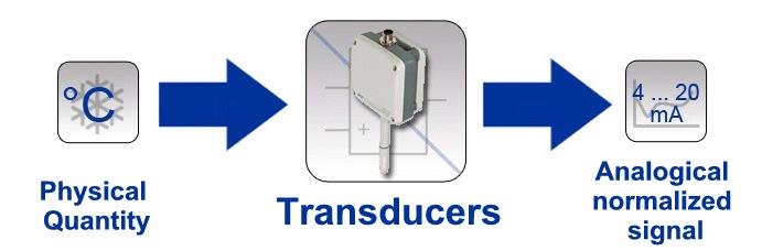
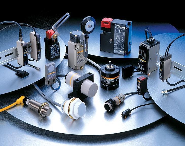
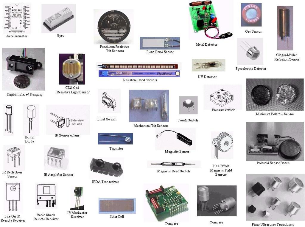
10 Sensors and Transducers A device capable of detecting and responding to physical stimuli such as movement, light, heat, pressure, humidity, gas concentration, etc., is known as a sensor. Physical quantities that can be measured electrically are primarily displacement, velocity, force, torque, strain, pressure, sound, acceleration, acoustic emission, humidity, gas concentration, etc. A number of physical effects can serve for converting a physical quantity in to electrical output signal. The most important ones are a change in resistance ( strain gauge, piezoresistive, potentiometric sensors), a change in capacitance or in inductance and a change in polarization ( piezoelectric)
11 According to American National Standards Institute A device which provides a usable output in response to a specified measurand Input Signal Output Signal Sensor A sensor acquires a physical quantity and converts it into a signal suitable for processing (e.g. optical, electrical, mechanical) Nowadays common sensors convert measurement of physical phenomena into an electrical signal
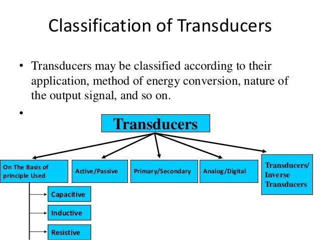
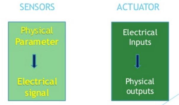
12 Types of Sensors Basically there are two types of sensors: Active and Passive sensors. Active Sensor A sensor is called active if no external source of power is required for measuring. An Active Sensor is known as a Transducer Passive Sensor Most other sensors are of the passive type. (i.e.,) they do not directly yield any output, rather they passively change their electric properties (change in resistance, capacitance, etc) as a function of the measurand. Such change can only be detected by applying an external source of power which will reveal the output signal in the form of a change in electric current or voltage.
13
14
15
16
17

18 Sensors in Use Example 1
19 Sensors in Use Example 2
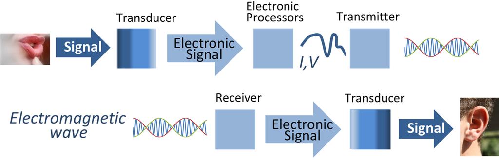
20 Measurement and Control The aim of any measuring system is to obtain information about a physical process and to find appropriate ways of presenting that information to an observer or to other technical systems. With electronic measuring systems the various instrument functions are realized by means of electronic components. A measuring system may be viewed as a transport channel for the exchanging of information between measurement objects and target objects.
21 Three main functions may be distinguished: data acquisition, data processing and data distribution Data acquisition: this involves acquiring information about the measurement object and converting it into electrical measurement data. Data processing: this involves the processing, selecting or manipulating in some other way of measurement data according to a prescribed program. Data distribution: the supplying of measurement data to the target object.
22 Since most physical measurement quantities are non-electric, they should first be converted into an electrical form in order to facilitate electronic processing. Such conversion is called transduction and it is effected by a transducer or sensor.
23 Signals Physical quantities that contain detectable messages are known as signals. The information carrier in any electrical signal is a voltage, a current, a charge or some other kind of electric parameter. The message contained in such a signal may constitute the result of a measurement The nature of the message cannot be deduced from its appearance. Processing techniques are necessary to derive the message content.
24 Types of signals Static or DC signals : the signal value remains constant during the measuring time interval. Quasi-static signals: the signal value varies just a little, according to a given physical quantity. An example of a quasi-static signal is drift. Dynamic signals: the signal value varies significantly during the observation period. Such signals are also termed AC signals (AC = alternating current or alternating voltages).
25 Another way to distinguish signals is on the basis of the difference between deterministic and Stochastic. Stochastic signal has the fact that its exact value is impossible to predict. Most measurement signals and interference signals, such as noise, belong to this category. Deterministic Periodic signals, characterized as x(t) = x(t + nt), in which T is the time of a signal period and n the integer. Transients, like the response of a system to a pulse-shaped input: the signal can be repeated (in other words predicted) by repeating the experiment under the same conditions.
26 Signal Conditioning The output signal from the sensor of a measurement system has generally to processed in some way to make it suitable for the next stage of the operation. the signal may be too small and have to be amplified, contain interference which has to be removed, be analogue and have to be made digital (vice versa), be a resistance change and have to be made in to a current change, be a voltage change and have to be made into a suitable size of current change, etc. All these changes can be referred to as signal conditioning.

27 For example, the output from a thermocouple is a small voltage (a few mv). A signal conditioning circuit or module is necessary to convert this millivolts into suitable size current signals and to provide noise rejection, linearization.
28 Signal Conditioning Processes 1. Protection to prevent damage to the next element (There can be series current limiting resistors, fuse breaks, polarity protection etc.,) 2. Getting the Signal into the right type of signals (Making the signal into DC voltage or current). Thus for example, the resistance change of the strain gauge has to be converted into a voltage change.this can be done by the use of Wheatstone bridge. 3. Getting the level of the signal right. (Thermo couple to microprocessor : mv Volts), Op-Amps widely used for this amplification. 4. Eliminating or reducing Noise: Filters may be used to eliminate main noise (50 Hz) from the signal for example. 5. Signal Manipulation: Making it a linear function of some variable. (ie) a nonlinear signal is conditioned to a linear one.
29 Noise With reference to an electrical system, noise may be defined as any unwanted form of energy which tends to interfere with proper reception and reproduction of wanted signal. OR The noise is a summation of unwanted or disturbing energy from natural and sometimes man-made sources. OR Noise is an unwanted disturbances superposed upon a useful signal that tend to be obscure its information content.

30 Noise in an electronic devices varies greatly, as it can be produced by several different effects. Noise is a fundamental parameter to be considered in an electronic design as it typically limits the overall performance of the system
31 Impulses are unwanted spikes in analog or in digital signals.
32 Classification of Noise Noise may be put into following two categories. 1. Intrinsic noises or Instrumental Noise and 2. Extrinsic or External Noises i.e. noise whose sources are external. Intrinsic Noise The noise generated inside an investigated device or circuit. In linear systems the physical origin of noise is the discrete nature of charge carriers. This Noise is associated with each component of an instrument i.e., with the source, the input transducer, signal processing elements and output transducer. Noise is a complex composite that usually cannot be fully characterized. Certain kinds of instrumental noise are recognizable, such as: Characteristics Intrinsic noise is random in nature. This means that it is not possible to predict the amplitude of fluctuating voltage or current. The amplitude of intrinsic noise is very low usually 1uv. As for the frequency spectrum many noise mechanisms yields white noise i.e., the noise power is equally distributed over all frequencies.
33 Internal noise may be put into the following four categories.. 1. Thermal noise or white noise or Johnson noise 2. Shot noise. 3. Flicker Noise 4. Miscellaneous internal noise.
34 1. Thermal Noise or Johnson Noise or white Noise: Thermal noise is caused by the thermal agitation of electrons or other charge carriers in resistors, capacitors, radiation transducers, electrochemical cells and other resistive elements in an instruments. The magnitude of thermal noise is given by rms = 4kTR f where, rms = root mean square noise, f = frequency band width (Hz), k = Boltzmann constant (1.38 x J/K), T = temperature in Kelvin, R = resistance in ohms of the resistive element. Thermal noise can be decreased by narrowing the bandwidth, by lowering the electrical resistance and by lowering the temperature of instrument components.
35
36 2. Shot Noise: The most common type of noise is referred to as shot noise which is produced by the random arrival of 'electrons or holes at the output element, at the plate in a tube, or at the collector or drain in a transistor. Shot noise is encountered wherever electrons or other charged particles cross a junction. i rms = 2Ie f Where, i rms = root-mean-square current fluctuation, I = average direct current, e = charge on the electron (1.60 x C), f = band width of frequencies. Shot noise in a current measurement can be minimized only by reducing bandwidth.
37 3. Flicker Noise: Flicker noise is characterized as having a magnitude that is inversely proportional to the frequency of the signal being observed. FN = 1/f it is also called as Pink Noise. Flicker noise becomes significant at frequency lower than about 100 Hz. Flicker noise can be reduced significantly by using wirewound or metallic film resistors rather than the more common carbon composition type.
38 Impulses are unwanted spikes in analog or in digital signals.
39 Extrinsic noise The sources of extrinsic noise are situated outside the investigated circuit External noise may be classified into the following three types: 1. Atmospheric noises 2. Extraterrestrial noises 3. Manmade noises or industrial noises. This kind of noise is also called extraneous signals or spurious signals or perturbations.
40 Signal to Noise Ratio (SNR) Noise is important whenever we are dealing with weak signals. A more appropriate statement would be that noise is important whenever the amplitudes of the processed signals are similar to those of the exiting noise. Therefore what really matters is not the signal level, but the signal to noise (S/N) ratio. Low S/N ratios indicated vulnerability to noise, while high S/N ratios indicate immunity to noise.
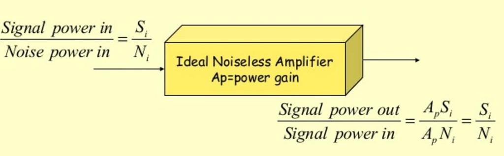
41 Two main reasons to calculate Noise Ratio To compare signal and the noise at the same point to ensure the noise is not excessive To compare two devices in order to evaluate their performance. The measure for this calculation is Signal To Noise Ratio. Signal-to-noise (SNR) is much more useful figure of merit than noise alone for describing the quality of an analytical method. SNR < 2 or 3 impossible to detect a signal. SNR = Ps / Pn Expressed as logarithmic function, SNR = 10 log Ps / Pn db
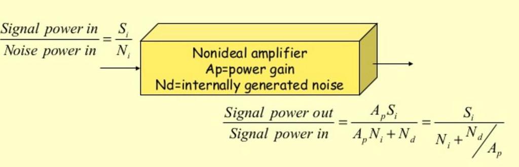
42 Noise Factor (F) and Noise Figure (NF) Noise factor is simply a ratio of input SNR to output SNR F = Input SNR / Output SNR Figure of Merit or Noise figure is used to indicate how much the SNR damage or deteriorates as a signal passes through a circuit. NF = 10 log F db For a perfect noise less circuit or component, F=1 and NF = 0 db
43
44 Lock In Amplifier Filters are frequency selective and therefore they can be utilized to reject noise or unwanted signals if the desired and spurious signals are located in different positions in the frequency spectrum. Such filters are of little use or no use if the signal and noise having nearly equal frequencies. Even in such situation the signal can be recovered if the noise is random and the desired signal is periodic or can be made periodic. Lock in Amplifier circuits provide a technique for the recovery of a coherent signal in the presence of noise. They can provide a very high degree of signal to noise ratio improvement without the drift associated with the production of high Q band bass filters.
45
46 Lock In Amplifier Block Diagram
47 A lock-in amplifier provides a DC output proportional to the AC signal under investigation (common with most AC measuring instruments). It is a combination of Phase Sensitive Detector (PSD) and a low pass filter (LPF). The special rectifier, called a phase-sensitive detector (PSD), which performs this AC to DC conversion forms the heart of the instrument/circuit. It is special in that it rectifies only the signal of interest while suppressing the effect of noise or interfering components which may accompany that signal. The traditional rectifier makes no distinction between signal and noise and produces errors due to rectified noise components. The noise at the input to a lock-in amplifier, however, is not rectified but appears at the output as an AC fluctuation. This means that the desired signal response, now a DC level, can be separated from the noise accompanying it in the output by means of a simple low-pass filter. Hence in a lock-in amplifier the final output is not affected by the presence of noise in the applied signal.
48 The periodic signal (mixed with noise ) is fed to the two throws of an electronic SPDT in two ways one directly and another through an inverting voltage follower. The SPDT in turn is actuated by a square wave reference signal. If the reference signal has the same frequency and the phase as those of the desired signal, then the switch will be in position 1 to sample the direct signal for the first half (ie). For phase angle 0 o to 180 o of the wave, and at position 2 to sample the inverted signal for the next half. As a result the PSD output will resemble that of a full wave rectifier and the LPF acting as averaging circuit and the circuit will give a steady DC output. If however, the input signal is of different frequency or of the same frequency but different phase from the reference signal, the LPF output will be zero or negligibly small if averaging is done over a sufficient time.
49
50 LIA are capable of reducing the noise and retrieving signals that are otherwise buried below the noise level. Improvements up to 85 db are relatively easy to obtain and up to 100 db reduction is possible. Their extensive range of applications includes signal processing from capacitate and inductive displacement transducers, radiometry, nuclear magnetic resonance and fringe position monitors. The central element of the LIA is the PSD
51 Mathematical Explanation for Lock in Amp Consider the case where a noise-free sinusoidal signal voltage Vin is being detected, where Vin = A cos ( t) is the angular frequency of the signal ( = 2πF) The lock-in amplifier is supplied with a reference signal at frequency F derived from the same source as the signal, and uses this to generate an internal reference signal of:- Vref = B cos ( t + ) where is a user-adjustable phase-shift introduced within the lock-in amplifier.
52 The detection process consists of multiplying these two components together so that the PSD output voltage is given by:- Vpsd = A cos ( t). B cos ( t + ) = AB cos t (cos t cos - sin t sin ) = AB(cos 2 t cos - cos t sin t sin ) = AB((½ + ½cos 2 t)cos - ½sin 2 t sin ) = ½AB((1+ cos 2 t)cos - sin 2 t sin ) = ½AB(cos + cos 2 t cos - sin 2 t sin ) = ½ABcos + ½AB(cos 2 t cos - sin 2 t sin ) = ½AB cos + ½ABcos(2 t + )
53 If the magnitude, B, of the reference frequency is kept constant, then the output from the phase-sensitive detector is a DC signal which is:- proportional to the magnitude of the input signal A proportional to the cosine of the angle,, between it and the reference signal modulated at 2 t, i.e. it contains components at twice the reference frequency.
54 The output from the PSD then passes to a low-pass filter which removes the 2wt component, leaving the output of the lock-in amplifier as the required DC signal. In a practical situation the signal will usually be accompanied by noise, but it can be shown that as long as there is no consistent phase (and therefore by implication frequency) relationship between the noise and the signal, the output of the multiplier due to the noise voltages will not be steady and can therefore be removed by the output filter.
55 LIA usage
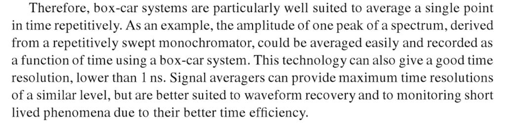
56 Box-Car Integrator or Averager
57 Box-Car integrators or averager provides a method of averaging out the noise signals and of thus improving signal to noise ratio. operation The system employs a triggering signal which is time referenced to the signal being averaged. This variable delay allows a particular section of the response signal to be selected. The sample and hold circuit is opened for a short aperture period and the signal within the gate width of the sample and hold circuit is stored. Repetition of the signal allows the portion of the signal at exactly the same time relative to the trigger to be selected. The system then averages the signal in this portion of the waveform. As the number of repetitions increases, the signal to noise ratio of the averaged signal improves. The improvement is proportional to the root of the number of repetitions. Automatic systems are available which scan the whole of the waveform, with an internally selected gage width to ensure that over a series of repetitions of the signal each section is averaged several times.
58
59
60 Sample and Hold Circuit A typical data acquisition system receives signal from a number of different sources and transmits these signals in suitable form to a processing unit or a communication channel. A multiplexer selects each channel in sequence, and then the analog information is converted into a constant voltage over the gating-time interval by means of a Sample and Hold Circuit. A simple S/H circuit is based on a high speed switch and a Capacitor.
61 When the switch is closed, the capacitor quickly charges or discharges so that its voltage, and hence the output voltage equals the input voltage. If the switch is not opened the capacitor simply holds its charge and its voltage remains constant. The circuit is used to take a sample of varying voltage by closing the switch, and then to hold that value by opening the switch.
62 The simple S/H has the following drawbacks When the Switch is closed, the capacitor represents very low impedance to the source and hence loads it heavily the result is distortion in the input signal. If the source has high output resistance, the time taken by the capacitor to charge increases the result is reduction in speed. To overcome these problems, MOSFET switches, and buffer amplifiers (voltage followers) are used.
63
64 In practice the switch may be a relay (For very low frequency), a sampling diode bridge gate, a bipolar transistor switch or a MOSFET controlled by a gating signal. The MOSFET makes an excellent chopper because its offset voltage when ON (~5 micro volt) is much smaller than that of a BJT. - Signal Input from buffer Amplifier - + LM102 Vo Control Signal
65 A negative pulse at the gate of the P-Channel MosFET will turn the switch ON, and the holding capacitor C will charge with a time constant RONC to the instantaneous value of the input voltage. In the absence of a negative pulse, the Switch is in the OFF state and the capacitor is isolated from any load through the Op-Amp. Thus it will hold the voltage impressed upon in it. For effective S/H polycarbonate, polyethylene or Teflon dielectric capacitors are used. Aperture time: The delay between the time that the pulse is applied to the switch and the actual time the switch closes. Acquisition Time: Time taken by the capacitor to change from one level of holding value to the new value of input voltage after the switch is closed.
66
LINEAR IC APPLICATIONS
 1 B.Tech III Year I Semester (R09) Regular & Supplementary Examinations December/January 2013/14 1 (a) Why is R e in an emitter-coupled differential amplifier replaced by a constant current source? (b)
Analytical Chemistry II
 Analytical Chemistry II L3: Signal processing (selected slides) Semiconductor devices Apart from resistors and capacitors, electronic circuits often contain nonlinear devices: transistors and diodes. The
DMI COLLEGE OF ENGINEERING
 DMI COLLEGE OF ENGINEERING DEPARTMENT OF ELECTRONICS & COMMUNICATION ENGINEERING EC8453 - LINEAR INTEGRATED CIRCUITS Question Bank (II-ECE) UNIT I BASICS OF OPERATIONAL AMPLIFIERS PART A 1.Mention the
The steeper the phase shift as a function of frequency φ(ω) the more stable the frequency of oscillation
 the more stable the frequency of oscillation") It should be noted that the frequency of oscillation ω o is determined by the phase characteristics of the feedback loop. the loop oscillates at the frequency for which the phase is zero The steeper the
It should be noted that the frequency of oscillation ω o is determined by the phase characteristics of the feedback loop. the loop oscillates at the frequency for which the phase is zero The steeper the
Summer 2015 Examination
 Summer 2015 Examination Subject Code: 17445 Model Answer Important Instructions to examiners: 1) The answers should be examined by key words and not as word-to-word as given in the model answer scheme.
Difference between BJTs and FETs. Junction Field Effect Transistors (JFET)
") Difference between BJTs and FETs Transistors can be categorized according to their structure, and two of the more commonly known transistor structures, are the BJT and FET. The comparison between BJTs
Difference between BJTs and FETs Transistors can be categorized according to their structure, and two of the more commonly known transistor structures, are the BJT and FET. The comparison between BJTs
Differential Amplifier : input. resistance. Differential amplifiers are widely used in engineering instrumentation
 Differential Amplifier : input resistance Differential amplifiers are widely used in engineering instrumentation Differential Amplifier : input resistance v 2 v 1 ir 1 ir 1 2iR 1 R in v 2 i v 1 2R 1 Differential
Speed Control of DC Motor Using Phase-Locked Loop
 Speed Control of DC Motor Using Phase-Locked Loop Authors Shaunak Vyas Darshit Shah Affiliations B.Tech. Electrical, Nirma University, Ahmedabad E-mail shaunak_vyas1@yahoo.co.in darshit_shah1@yahoo.co.in
Today s menu. Last lecture. Series mode interference. Noise and interferences R/2 V SM Z L. E Th R/2. Voltage transmission system
 Last lecture Introduction to statistics s? Random? Deterministic? Probability density functions and probabilities? Properties of random signals. Today s menu Effects of noise and interferences in measurement
Glossary of VCO terms
 Glossary of VCO terms VOLTAGE CONTROLLED OSCILLATOR (VCO): This is an oscillator designed so the output frequency can be changed by applying a voltage to its control port or tuning port. FREQUENCY TUNING
Massachusetts Institute of Technology MIT
 Massachusetts Institute of Technology MIT Real Time Wireless Electrocardiogram (ECG) Monitoring System Introductory Analog Electronics Laboratory Guilherme K. Kolotelo, Rogers G. Reichert Cambridge, MA
Part A: Question & Answers UNIT I AMPLITUDE MODULATION
 PANDIAN SARASWATHI YADAV ENGINEERING COLLEGE DEPARTMENT OF ELECTRONICS & COMMUNICATON ENGG. Branch: ECE EC6402 COMMUNICATION THEORY Semester: IV Part A: Question & Answers UNIT I AMPLITUDE MODULATION 1.
Let us consider the following block diagram of a feedback amplifier with input voltage feedback fraction,, be positive i.e. in phase.
 P a g e 2 Contents 1) Oscillators 3 Sinusoidal Oscillators Phase Shift Oscillators 4 Wien Bridge Oscillators 4 Square Wave Generator 5 Triangular Wave Generator Using Square Wave Generator 6 Using Comparator
NOISE INTERNAL NOISE. Thermal Noise
 NOISE INTERNAL NOISE......1 Thermal Noise......1 Shot Noise......2 Frequency dependent noise......3 THERMAL NOISE......3 Resistors in series......3 Resistors in parallel......4 Power Spectral Density......4
MAHARASHTRA STATE BOARD OF TECHNICAL EDUCATION (Autonomous) (ISO/IEC Certified) MODEL ANSWER
 (ISO/IEC Certified) MODEL ANSWER") Important Instructions to examiners: 1) The answers should be examined by key words and not as word-to-word as given in the model answer scheme. 2) The model answer and the answer written by candidate
Important Instructions to examiners: 1) The answers should be examined by key words and not as word-to-word as given in the model answer scheme. 2) The model answer and the answer written by candidate
Data Conversion Circuits & Modulation Techniques. Subhasish Chandra Assistant Professor Department of Physics Institute of Forensic Science, Nagpur
 Data Conversion Circuits & Modulation Techniques Subhasish Chandra Assistant Professor Department of Physics Institute of Forensic Science, Nagpur Data Conversion Circuits 2 Digital systems are being used
tyuiopasdfghjklzxcvbnmqwertyuiopas dfghjklzxcvbnmqwertyuiopasdfghjklzx cvbnmqwertyuiopasdfghjklzxcvbnmq
 qwertyuiopasdfghjklzxcvbnmqwertyui opasdfghjklzxcvbnmqwertyuiopasdfgh jklzxcvbnmqwertyuiopasdfghjklzxcvb nmqwertyuiopasdfghjklzxcvbnmqwer Instrumentation Device Components Semester 2 nd tyuiopasdfghjklzxcvbnmqwertyuiopas
Introduction to Measurement Systems
 MFE 3004 Mechatronics I Measurement Systems Dr Conrad Pace Page 4.1 Introduction to Measurement Systems Role of Measurement Systems Detection receive an external stimulus (ex. Displacement) Selection measurement
Physics 160 Lecture 11. R. Johnson May 4, 2015
 Physics 160 Lecture 11 R. Johnson May 4, 2015 Two Solutions to the Miller Effect Putting a matching resistor on the collector of Q 1 would be a big mistake, as it would give no benefit and would produce
B.E. SEMESTER III (ELECTRICAL) SUBJECT CODE: X30902 Subject Name: Analog & Digital Electronics
 SUBJECT CODE: X30902 Subject Name: Analog & Digital Electronics") B.E. SEMESTER III (ELECTRICAL) SUBJECT CODE: X30902 Subject Name: Analog & Digital Electronics Sr. No. Date TITLE To From Marks Sign 1 To verify the application of op-amp as an Inverting Amplifier 2 To
B.E. SEMESTER III (ELECTRICAL) SUBJECT CODE: X30902 Subject Name: Analog & Digital Electronics Sr. No. Date TITLE To From Marks Sign 1 To verify the application of op-amp as an Inverting Amplifier 2 To
Hours / 100 Marks Seat No.
 17445 21415 3 Hours / 100 Seat No. Instructions (1) All Questions are Compulsory. (2) Illustrate your answers with neat sketches wherever necessary. (3) Figures to the right indicate full marks. (4) Assume
Dev Bhoomi Institute Of Technology Department of Electronics and Communication Engineering PRACTICAL INSTRUCTION SHEET REV. NO. : REV.
 Dev Bhoomi Institute Of Technology Department of Electronics and Communication Engineering PRACTICAL INSTRUCTION SHEET LABORATORY MANUAL EXPERIMENT NO. ISSUE NO. : ISSUE DATE: July 200 REV. NO. : REV.
Advanced Measurements
 Albaha University Faculty of Engineering Mechanical Engineering Department Lecture 9: Wheatstone Bridge and Filters Ossama Abouelatta o_abouelatta@yahoo.com Mechanical Engineering Department Faculty of
AC LAB ECE-D ecestudy.wordpress.com
 PART B EXPERIMENT NO: 1 AIM: PULSE AMPLITUDE MODULATION (PAM) & DEMODULATION DATE: To study Pulse Amplitude modulation and demodulation process with relevant waveforms. APPARATUS: 1. Pulse amplitude modulation
ETEK TECHNOLOGY CO., LTD.
 Trainer Model: ETEK DCS-6000-07 FSK Modulator ETEK TECHNOLOGY CO., LTD. E-mail: etek21@ms59.hinet.net mlher@etek21.com.tw http: // www.etek21.com.tw Digital Communication Systems (ETEK DCS-6000) 13-1:
IT.MLD900 SENSORS AND TRANSDUCERS TRAINER. Signal Conditioning
 SENSORS AND TRANSDUCERS TRAINER IT.MLD900 The s and Instrumentation Trainer introduces students to input sensors, output actuators, signal conditioning circuits, and display devices through a wide range
Read pp Impossible to detect a signal when the S/N becomes less than about 2. mean Std. Deviation. X s S N 1 RSD
 Chapter 5 Signals and Noise Read pp. 110-123 Impossible to detect a signal when the S/N becomes less than about 2. S N = mean Std. Deviation = X s = 1 RSD Signal Transduction Internet: Wikipedia (Signals
Chapter 2 Signal Conditioning, Propagation, and Conversion
 09/0 PHY 4330 Instrumentation I Chapter Signal Conditioning, Propagation, and Conversion. Amplification (Review of Op-amps) Reference: D. A. Bell, Operational Amplifiers Applications, Troubleshooting,
CH85CH2202-0/85/ $1.00
 SYNCHRONIZATION AND TRACKING WITH SYNCHRONOUS OSCILLATORS Vasil Uzunoglu and Marvin H. White Fairchild Industries Germantown, Maryland Lehigh University Bethlehem, Pennsylvania ABSTRACT A Synchronous Oscillator
CHAPTER 6 DIGITAL INSTRUMENTS
 CHAPTER 6 DIGITAL INSTRUMENTS 1 LECTURE CONTENTS 6.1 Logic Gates 6.2 Digital Instruments 6.3 Analog to Digital Converter 6.4 Electronic Counter 6.6 Digital Multimeters 2 6.1 Logic Gates 3 AND Gate The
THE BENEFITS OF DSP LOCK-IN AMPLIFIERS
 THE BENEFITS OF DSP LOCK-IN AMPLIFIERS If you never heard of or don t understand the term lock-in amplifier, you re in good company. With the exception of the optics industry where virtually every major
Applied Electronics II
 Applied Electronics II Chapter 3: Operational Amplifier Part 1- Op Amp Basics School of Electrical and Computer Engineering Addis Ababa Institute of Technology Addis Ababa University Daniel D./Getachew
4. Digital Measurement of Electrical Quantities
 4.1. Concept of Digital Systems Concept A digital system is a combination of devices designed for manipulating physical quantities or information represented in digital from, i.e. they can take only discrete
B.Tech II Year II Semester (R13) Supplementary Examinations May/June 2017 ANALOG COMMUNICATION SYSTEMS (Electronics and Communication Engineering)
 Supplementary Examinations May/June 2017 ANALOG COMMUNICATION SYSTEMS (Electronics and Communication Engineering)") Code: 13A04404 R13 B.Tech II Year II Semester (R13) Supplementary Examinations May/June 2017 ANALOG COMMUNICATION SYSTEMS (Electronics and Communication Engineering) Time: 3 hours Max. Marks: 70 PART A
Code: 13A04404 R13 B.Tech II Year II Semester (R13) Supplementary Examinations May/June 2017 ANALOG COMMUNICATION SYSTEMS (Electronics and Communication Engineering) Time: 3 hours Max. Marks: 70 PART A
Preface... iii. Chapter 1: Diodes and Circuits... 1
 Table of Contents Preface... iii Chapter 1: Diodes and Circuits... 1 1.1 Introduction... 1 1.2 Structure of an Atom... 2 1.3 Classification of Solid Materials on the Basis of Conductivity... 2 1.4 Atomic
MODEL ANSWER SUMMER 17 EXAMINATION Subject Title: Linear Integrated Circuit Subject Code:
 MODEL ANSWER SUMMER 17 EXAMINATION Subject Title: Linear Integrated Circuit Subject Code: Important Instructions to examiners: 1) The answers should be examined by key words and not as word-to-word as
 VALLIAMMAI ENGINEERING COLLEGE SRM Nagar, Kattankulathur 603 203. DEPARTMENT OF ELECTRONICS & COMMUNICATION ENGINEERING QUESTION BANK SUBJECT : EC6404 LINEAR INTEGRATED CIRCUITS SEM / YEAR: IV / II year
Module 1: Introduction to Experimental Techniques Lecture 2: Sources of error. The Lecture Contains: Sources of Error in Measurement
 The Lecture Contains: Sources of Error in Measurement Signal-To-Noise Ratio Analog-to-Digital Conversion of Measurement Data A/D Conversion Digitalization Errors due to A/D Conversion file:///g /optical_measurement/lecture2/2_1.htm[5/7/2012
HIGH LOW Astable multivibrators HIGH LOW 1:1
 1. Multivibrators A multivibrator circuit oscillates between a HIGH state and a LOW state producing a continuous output. Astable multivibrators generally have an even 50% duty cycle, that is that 50% of
UNIT 2. Q.1) Describe the functioning of standard signal generator. Ans. Electronic Measurements & Instrumentation
 Describe the functioning of standard signal generator. Ans. Electronic Measurements & Instrumentation") UNIT 2 Q.1) Describe the functioning of standard signal generator Ans. STANDARD SIGNAL GENERATOR A standard signal generator produces known and controllable voltages. It is used as power source for the
UNIT 2 Q.1) Describe the functioning of standard signal generator Ans. STANDARD SIGNAL GENERATOR A standard signal generator produces known and controllable voltages. It is used as power source for the
Table of Contents...2. About the Tutorial...6. Audience...6. Prerequisites...6. Copyright & Disclaimer EMI INTRODUCTION Voltmeter...
 1 Table of Contents Table of Contents...2 About the Tutorial...6 Audience...6 Prerequisites...6 Copyright & Disclaimer...6 1. EMI INTRODUCTION... 7 Voltmeter...7 Ammeter...8 Ohmmeter...8 Multimeter...9
Introductory Electronics for Scientists and Engineers
 Introductory Electronics for Scientists and Engineers Second Edition ROBERT E. SIMPSON University of New Hampshire Allyn and Bacon, Inc. Boston London Sydney Toronto Contents Preface xiü 1 Direct Current
Chapter 2 Analog-to-Digital Conversion...
 Chapter... 5 This chapter examines general considerations for analog-to-digital converter (ADC) measurements. Discussed are the four basic ADC types, providing a general description of each while comparing
WINTER 14 EXAMINATION
 Subject Code:173 WINTER 14 EXAMINATION Model Answer Important Instructions to examiners: 1) The answers should be examined by key words and not as word-to-word as given in the model answer scheme. 2) The
Electronic Instrumentation & Automation. ET-7th semester. By : Rahul Sharma ET & TC Deptt. RCET, Bhilai
 Electronic Instrumentation & Automation ET-7th semester By : Rahul Sharma ET & TC Deptt. RCET, Bhilai UNIT: III Voltage and Current Measurements Digital Voltmeters: Non-Integrating type, Integrating Type,
Signal Conditioning Systems
 Note-13 1 Signal Conditioning Systems 2 Generalized Measurement System: The output signal from a sensor has generally to be processed or conditioned to make it suitable for the next stage Signal conditioning
Interface Electronic Circuits
 Lecture (5) Interface Electronic Circuits Part: 1 Prof. Kasim M. Al-Aubidy Philadelphia University-Jordan AMSS-MSc Prof. Kasim Al-Aubidy 1 Interface Circuits: An interface circuit is a signal conditioning
two computers. 2- Providing a channel between them for transmitting and receiving the signals through it.
 1. Introduction: Communication is the process of transmitting the messages that carrying information, where the two computers can be communicated with each other if the two conditions are available: 1-
Chapter 6. FM Circuits
 Chapter 6 FM Circuits Topics Covered 6-1: Frequency Modulators 6-2: Frequency Demodulators Objectives You should be able to: Explain the operation of an FM modulators and demodulators. Compare and contrast;
LM13600 Dual Operational Transconductance Amplifiers with Linearizing Diodes and Buffers
 LM13600 Dual Operational Transconductance Amplifiers with Linearizing Diodes and Buffers General Description The LM13600 series consists of two current controlled transconductance amplifiers each with
1 Signals and systems, A. V. Oppenhaim, A. S. Willsky, Prentice Hall, 2 nd edition, FUNDAMENTALS. Electrical Engineering. 2.
 1 Signals and systems, A. V. Oppenhaim, A. S. Willsky, Prentice Hall, 2 nd edition, 1996. FUNDAMENTALS Electrical Engineering 2.Processing - Analog data An analog signal is a signal that varies continuously.
UNIT-I CIRCUIT CONFIGURATION FOR LINEAR
 UNIT-I CIRCUIT CONFIGURATION FOR LINEAR ICs 2 marks questions 1.Mention the advantages of integrated circuits. *Miniaturisation and hence increased equipment density. *Cost reduction due to batch processing.
EC202- ELECTRONIC CIRCUITS II Unit- I -FEEEDBACK AMPLIFIER
 EC202- ELECTRONIC CIRCUITS II Unit- I -FEEEDBACK AMPLIFIER 1. What is feedback? What are the types of feedback? 2. Define positive feedback. What are its merits and demerits? 3. Define negative feedback.
AERO2705 Space Engineering 1 Week 7 The University of Sydney
 AERO2705 Space Engineering 1 Week 7 The University of Sydney Presenter Mr. Warwick Holmes Executive Director Space Engineering School of Aerospace, Mechanical and Mechatronic Engineering The University
ni.com Sensor Measurement Fundamentals Series
 Sensor Measurement Fundamentals Series Introduction to Data Acquisition Basics and Terminology Litkei Márton District Sales Manager National Instruments What Is Data Acquisition (DAQ)? 3 Why Measure? Engineers
Department of Electronics & Communication Engineering LAB MANUAL SUBJECT: DIGITAL COMMUNICATION LABORATORY [ECE324] (Branch: ECE)
![Department of Electronics & Communication Engineering LAB MANUAL SUBJECT: DIGITAL COMMUNICATION LABORATORY [ECE324] (Branch: ECE)](/thumbs/96/127341232.jpg "Department of Electronics & Communication Engineering LAB MANUAL SUBJECT: DIGITAL COMMUNICATION LABORATORY [ECE324] (Branch: ECE)") Department of Electronics & Communication Engineering LAB MANUAL SUBJECT: DIGITAL COMMUNICATION LABORATORY [ECE324] B.Tech Year 3 rd, Semester - 5 th (Branch: ECE) Version: 01 st August 2018 The LNM Institute
Department of Electronics & Communication Engineering LAB MANUAL SUBJECT: DIGITAL COMMUNICATION LABORATORY [ECE324] B.Tech Year 3 rd, Semester - 5 th (Branch: ECE) Version: 01 st August 2018 The LNM Institute
About the Tutorial. Audience. Prerequisites. Copyright & Disclaimer. Linear Integrated Circuits Applications
 About the Tutorial Linear Integrated Circuits are solid state analog devices that can operate over a continuous range of input signals. Theoretically, they are characterized by an infinite number of operating
Q.P. Code : [ TURN OVER]
![Q.P. Code : [ TURN OVER]](/thumbs/90/103239233.jpg "Q.P. Code : [ TURN OVER]") Q.P. Code : 587801 8ADF85B2CAF8DDC703193679392A86308ADF85B2CAF8DDC703193679392A86308ADF85B2CAF8DDC703193679392A86308ADF85B2CAF8DDC703193679392A86308ADF85B2CAF8DDC70 6308ADF85B2CAF8DDC703193679392A86308ADF85B2CAF8DDC703193679392A86308ADF85B2CAF8DDC703193679392A86308ADF85B2CAF8DDC703193679392A86308ADF85B2CAF8DDC703
Q.P. Code : 587801 8ADF85B2CAF8DDC703193679392A86308ADF85B2CAF8DDC703193679392A86308ADF85B2CAF8DDC703193679392A86308ADF85B2CAF8DDC703193679392A86308ADF85B2CAF8DDC70 6308ADF85B2CAF8DDC703193679392A86308ADF85B2CAF8DDC703193679392A86308ADF85B2CAF8DDC703193679392A86308ADF85B2CAF8DDC703193679392A86308ADF85B2CAF8DDC703
GOVERNMENT OF KARNATAKA KARNATAKA STATE PRE-UNIVERSITY EDUCATION EXAMINATION BOARD II YEAR PUC EXAMINATION MARCH-2013 SCHEME OF VALUATION
 GOVERNMENT OF KARNATAKA KARNATAKA STATE PRE-UNIVERSITY EDUCATION EXAMINATION BOARD II YEAR PUC EXAMINATION MARCH-03 SCHEME OF VALUATION Subject Code: 0 Subject: PART - A 0. What does the arrow mark indicate
ericssonz LBI-38640E MAINTENANCE MANUAL FOR VHF TRANSMITTER SYNTHESIZER MODULE 19D902780G1 DESCRIPTION
 MAINTENANCE MANUAL FOR VHF TRANSMITTER SYNTHESIZER MODULE 19D902780G1 TABLE OF CONTENTS Page DESCRIPTION........................................... Front Cover GENERAL SPECIFICATIONS...................................
Experiment No. 3 Pre-Lab Phase Locked Loops and Frequency Modulation
 Experiment No. 3 Pre-Lab Phase Locked Loops and Frequency Modulation The Pre-Labs are informational and although they follow the procedures in the experiment, they are to be completed outside of the laboratory.
Operational Amplifiers
 Operational Amplifiers Table of contents 1. Design 1.1. The Differential Amplifier 1.2. Level Shifter 1.3. Power Amplifier 2. Characteristics 3. The Opamp without NFB 4. Linear Amplifiers 4.1. The Non-Inverting
Capacitive Touch Sensing Tone Generator. Corey Cleveland and Eric Ponce
 Capacitive Touch Sensing Tone Generator Corey Cleveland and Eric Ponce Table of Contents Introduction Capacitive Sensing Overview Reference Oscillator Capacitive Grid Phase Detector Signal Transformer
Lecture 3 Concepts for the Data Communications and Computer Interconnection
 Lecture 3 Concepts for the Data Communications and Computer Interconnection Aim: overview of existing methods and techniques Terms used: -Data entities conveying meaning (of information) -Signals data
Devices and Op-Amps p. 1 Introduction to Diodes p. 3 Introduction to Diodes p. 4 Inside the Diode p. 6 Three Diode Models p. 10 Computer Circuit
 Contents p. v Preface p. ix Devices and Op-Amps p. 1 Introduction to Diodes p. 3 Introduction to Diodes p. 4 Inside the Diode p. 6 Three Diode Models p. 10 Computer Circuit Analysis p. 16 MultiSIM Lab
Sensors (Transducer) Introduction By Sintayehu Challa
 Introduction By Sintayehu Challa") Sensors (Transducer) Introduction What are Sensors? Basically the quantities to be measured are Non-Electrical quantities such as temperature, pressure,displacement,humidity, fluid flow, speed etc, but
Sensors (Transducer) Introduction What are Sensors? Basically the quantities to be measured are Non-Electrical quantities such as temperature, pressure,displacement,humidity, fluid flow, speed etc, but
DESIGN TIP DT Variable Frequency Drive using IR215x Self-Oscillating IC s. By John Parry
 DESIGN TIP DT 98- International Rectifier 233 Kansas Street El Segundo CA 9245 USA riable Frequency Drive using IR25x Self-Oscillating IC s Purpose of this Design Tip By John Parry Applications such as
Module 2. Measurement Systems. Version 2 EE IIT, Kharagpur 1
 Module Measurement Systems Version EE IIT, Kharagpur 1 Lesson 9 Signal Conditioning Circuits Version EE IIT, Kharagpur Instructional Objective The reader, after going through the lesson would be able to:
T.J.Moir AUT University Auckland. The Ph ase Lock ed Loop.
 T.J.Moir AUT University Auckland The Ph ase Lock ed Loop. 1.Introduction The Phase-Locked Loop (PLL) is one of the most commonly used integrated circuits (ICs) in use in modern communications systems.
4/30/2012. General Class Element 3 Course Presentation. Practical Circuits. Practical Circuits. Subelement G7. 2 Exam Questions, 2 Groups
 General Class Element 3 Course Presentation ti ELEMENT 3 SUB ELEMENTS General Licensing Class Subelement G7 2 Exam Questions, 2 Groups G1 Commission s Rules G2 Operating Procedures G3 Radio Wave Propagation
225 Lock-in Amplifier
 225 Lock-in Amplifier 225.02 Bentham Instruments Ltd 1 2 Bentham Instruments Ltd 225.02 1. WHAT IS A LOCK-IN? There are a number of ways of visualising the operation and significance of a lock-in amplifier.
Transistor Digital Circuits
 Recapitulation Transistor Digital Circuits The transistor Operating principle and regions Utilization of the transistor Transfer characteristics, symbols Controlled switch model BJT digital circuits MOSFET
Application Note (A12)
") Application Note (A2) The Benefits of DSP Lock-in Amplifiers Revision: A September 996 Gooch & Housego 4632 36 th Street, Orlando, FL 328 Tel: 47 422 37 Fax: 47 648 542 Email: sales@goochandhousego.com
Application Note (A2) The Benefits of DSP Lock-in Amplifiers Revision: A September 996 Gooch & Housego 4632 36 th Street, Orlando, FL 328 Tel: 47 422 37 Fax: 47 648 542 Email: sales@goochandhousego.com
14.2 Photodiodes 411
 14.2 Photodiodes 411 Maximum reverse voltage is specified for Ge and Si photodiodes and photoconductive cells. Exceeding this voltage can cause the breakdown and severe deterioration of the sensor s performance.
FSK DEMODULATOR / TONE DECODER
 FSK DEMODULATOR / TONE DECODER GENERAL DESCRIPTION The is a monolithic phase-locked loop (PLL) system especially designed for data communications. It is particularly well suited for FSK modem applications,
CHAPTER 2 A SERIES PARALLEL RESONANT CONVERTER WITH OPEN LOOP CONTROL
 14 CHAPTER 2 A SERIES PARALLEL RESONANT CONVERTER WITH OPEN LOOP CONTROL 2.1 INTRODUCTION Power electronics devices have many advantages over the traditional power devices in many aspects such as converting
Department of Electronics & Telecommunication Engg. LAB MANUAL. B.Tech V Semester [ ] (Branch: ETE)
![Department of Electronics & Telecommunication Engg. LAB MANUAL. B.Tech V Semester [ ] (Branch: ETE)](/thumbs/86/93078052.jpg "Department of Electronics & Telecommunication Engg. LAB MANUAL. B.Tech V Semester [ ] (Branch: ETE)") Department of Electronics & Telecommunication Engg. LAB MANUAL SUBJECT:-DIGITAL COMMUNICATION SYSTEM [BTEC-501] B.Tech V Semester [2013-14] (Branch: ETE) KCT COLLEGE OF ENGG & TECH., FATEHGARH PUNJAB TECHNICAL
Department of Electronics & Telecommunication Engg. LAB MANUAL SUBJECT:-DIGITAL COMMUNICATION SYSTEM [BTEC-501] B.Tech V Semester [2013-14] (Branch: ETE) KCT COLLEGE OF ENGG & TECH., FATEHGARH PUNJAB TECHNICAL
Special-Purpose Operational Amplifier Circuits
 Special-Purpose Operational Amplifier Circuits Instrumentation Amplifier An instrumentation amplifier (IA) is a differential voltagegain device that amplifies the difference between the voltages existing
HF Receivers, Part 2
 HF Receivers, Part 2 Superhet building blocks: AM, SSB/CW, FM receivers Adam Farson VA7OJ View an excellent tutorial on receivers NSARC HF Operators HF Receivers 2 1 The RF Amplifier (Preamp)! Typical
EEE 432 Measurement and Instrumentation
 EEE 432 Measurement and Instrumentation Lecture 6 Measurement noise and signal processing Prof. Dr. Murat Aşkar İzmir University of Economics Dept. of Electrical and Electronics Engineering Measurement
LESSON PLAN. SUBJECT: LINEAR IC S AND APPLICATION NO OF HOURS: 52 FACULTY NAME: Mr. Lokesh.L, Hema. B DEPT: ECE. Portions to be covered
 LESSON PLAN SUBJECT: LINEAR IC S AND APPLICATION SUB CODE: 15EC46 NO OF HOURS: 52 FACULTY NAME: Mr. Lokesh.L, Hema. B DEPT: ECE Class# Chapter title/reference literature Portions to be covered MODULE I
EKT 314 ELECTRONIC INSTRUMENTATION
 EKT 314 ELECTRONIC INSTRUMENTATION Elektronik Instrumentasi Semester 2 2012/2013 Chapter 3 Analog Signal Conditioning Session 2 Mr. Fazrul Faiz Zakaria school of computer and communication engineering.
Electronic Measurements & Instrumentation. 1. Draw the Maxwell s Bridge Circuit and derives the expression for the unknown element at balance?
 UNIT -6 1. Draw the Maxwell s Bridge Circuit and derives the expression for the unknown element at balance? Ans: Maxwell's bridge, shown in Fig. 1.1, measures an unknown inductance in of standard arm offers
Field Effect Transistors
 Field Effect Transistors Purpose In this experiment we introduce field effect transistors (FETs). We will measure the output characteristics of a FET, and then construct a common-source amplifier stage,
Interface to the Analog World
 Interface to the Analog World Liyuan Liu and Zhihua Wang 1 Sensoring the World Sensors or detectors are ubiquitous in the world. Everyday millions of them are produced and integrated into various kinds
Electronics Interview Questions
 Electronics Interview Questions 1. What is Electronic? The study and use of electrical devices that operate by controlling the flow of electrons or other electrically charged particles. 2. What is communication?
CHAPTER 3. Instrumentation Amplifier (IA) Background. 3.1 Introduction. 3.2 Instrumentation Amplifier Architecture and Configurations
 Background. 3.1 Introduction. 3.2 Instrumentation Amplifier Architecture and Configurations") CHAPTER 3 Instrumentation Amplifier (IA) Background 3.1 Introduction The IAs are key circuits in many sensor readout systems where, there is a need to amplify small differential signals in the presence
CHAPTER 3 Instrumentation Amplifier (IA) Background 3.1 Introduction The IAs are key circuits in many sensor readout systems where, there is a need to amplify small differential signals in the presence
Simple Methods for Detecting Zero Crossing
 Proceedings of The 29 th Annual Conference of the IEEE Industrial Electronics Society Paper # 000291 1 Simple Methods for Detecting Zero Crossing R.W. Wall, Senior Member, IEEE Abstract Affects of noise,
Chapter 3. Question Mar No
 Chapter 3 Sr Question Mar No k. 1 Write any two drawbacks of TRF radio receiver 1. Instability due to oscillatory nature of RF amplifier.. Variation in bandwidth over tuning range. 3. Insufficient selectivity
Introduction. sig. ref. sig
 Introduction A lock-in amplifier, in common with most AC indicating instruments, provides a DC output proportional to the AC signal under investigation. The special rectifier, called a phase-sensitive
Small signal Amplifier stages. Figure 5.2 Classification of power amplifiers
 5.1 Introduction When the power requirement to drive the load is in terms of several Watts rather than mili-watts the power amplifiers are used. Power amplifiers form the last stage of multistage amplifiers.
UNIT III ANALOG MULTIPLIER AND PLL
 UNIT III ANALOG MULTIPLIER AND PLL PART A (2 MARKS) 1. What are the advantages of variable transconductance technique? [AUC MAY 2012] Good Accuracy Economical Simple to integrate Reduced error Higher bandwidth
EE301 Electronics I , Fall
 EE301 Electronics I 2018-2019, Fall 1. Introduction to Microelectronics (1 Week/3 Hrs.) Introduction, Historical Background, Basic Consepts 2. Rewiev of Semiconductors (1 Week/3 Hrs.) Semiconductor materials
Downloaded from Downloaded from
 IV SEMESTER FINAL EXAMINATION- 2002 SUBJECT: BEG232EC, Instrumentation Candidates are required to give their answers in their own words as far as practicable. The figure in the margin indicates full marks.
INTEGRATED CIRCUITS. AN109 Microprocessor-compatible DACs Dec
 INTEGRATED CIRCUITS 1988 Dec DAC products are designed to convert a digital code to an analog signal. Since a common source of digital signals is the data bus of a microprocessor, DAC circuits that are
5. Transducers Definition and General Concept of Transducer Classification of Transducers
 5.1. Definition and General Concept of Definition The transducer is a device which converts one form of energy into another form. Examples: Mechanical transducer and Electrical transducer Electrical A
Module 5. DC to AC Converters. Version 2 EE IIT, Kharagpur 1
 Module 5 DC to AC Converters Version 2 EE IIT, Kharagpur 1 Lesson 37 Sine PWM and its Realization Version 2 EE IIT, Kharagpur 2 After completion of this lesson, the reader shall be able to: 1. Explain
CHAPTER 6 PHASE LOCKED LOOP ARCHITECTURE FOR ADC
 138 CHAPTER 6 PHASE LOCKED LOOP ARCHITECTURE FOR ADC 6.1 INTRODUCTION The Clock generator is a circuit that produces the timing or the clock signal for the operation in sequential circuits. The circuit
T6+ Analog I/O Section. Installation booklet for part numbers: 5/4-80A-115 5/4-90A-115 5/4-80A /4-90A-1224
 T and T+ are trade names of Trol Systems Inc. TSI reserves the right to make changes to the information contained in this manual without notice. publication /4A115MAN- rev:1 2001 TSI All rights reserved
Lecture 14 Interface Electronics (Part 2) ECE 5900/6900 Fundamentals of Sensor Design
 ECE 5900/6900 Fundamentals of Sensor Design") EE 4900: Fundamentals of Sensor Design 1 Lecture 14 Interface Electronics (Part 2) Interface Electronics (Part 2) 2 Linearizing Bridge Circuits (Sensor Tech Hand book) Precision Op amps, Auto Zero Op amps,
EE 4900: Fundamentals of Sensor Design 1 Lecture 14 Interface Electronics (Part 2) Interface Electronics (Part 2) 2 Linearizing Bridge Circuits (Sensor Tech Hand book) Precision Op amps, Auto Zero Op amps,