Special-Purpose Operational Amplifier Circuits
|
|
|
- Berenice Underwood
- 6 years ago
- Views:
Transcription
1 Special-Purpose Operational Amplifier Circuits
2 Instrumentation Amplifier An instrumentation amplifier (IA) is a differential voltagegain device that amplifies the difference between the voltages existing at its two input terminals. The main purpose is to amplify small signals that may be riding on large common-mode voltages. It is an integrated circuit that internally has three operational amplifiers and several resistors. The key characteristics are high input impedance, high common-mode rejection, low output offset, and low output impedance. Instrumentation amplifiers are commonly used in environments with high common mode noise such as in data acquisition systems where remote sensing of input variables is required
 The gain-setting")
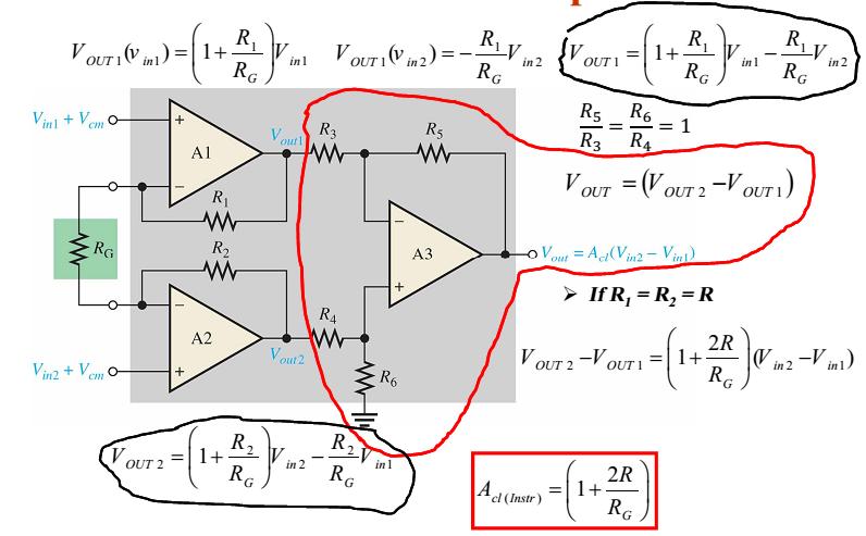
3 Instrumentation Amplifier Op-amps A1 and A2 are noninverting configurations that provide high input impedance and voltage gain. Op-amp A3 is used as a unity-gain differential amplifier with high-precision resistors that are all equal in value (R3 = R4 = R5 = R6) The gain-setting resistor, R G is connected externally.
4 Instrumentation Amplifier The overall closed-loop gain of the instrumentation amplifier is: AA cccc = 1 + 2RR RR GG Where R 1 = R 2 = R The gain of the instrumentation amplifier can be set by the value of the external resistor R G when R 1 and R 2 have a known fixed value. The external gain-setting resistor R G can be calculated for a desired voltage gain by RR GG = 2RR AA cccc 1
5 Instrumentation Amplifier
6 Instrumentation Amplifier
7 Instrumentation Amplifier Example Determine the value of the external gain-setting resistor R G for a certain IC instrumentation amplifier with R 1 = R 2 = 25 kω. The closed-loop voltage gain is to be 500. Solution RR GG = 2RR AA cccc 1 = 50 kkω Ω
8 Instrumentation Amplifier The instrumentation amplifier is normally used to measure small differential signal voltages that are superimposed on a common-mode voltage often much larger than the signal voltage. Applications include situations where a quantity is sensed by a remote device and the resulting small electrical signal is sent over a long line subject to electrical noise that produces common-mode voltages in the line.
9 AD622 Instrumentation Amplifier An external resistor must be used to achieve a voltage gain greater than unity. RG is connected between pins 1 and kkω RR GG = AA cccc 1
10 AD622 Instrumentation Amplifier What value of R G will set the gain to 35? R G 50.5 kω 50.5 kω = = A v = 1.5 kω
11 Instrumentation Amplifiers The bandwidth of any IA (or op-amp for that matter) is lower for higher gain. The graph shows the BW for various gains for the AD What is the BW for a gain of 35? 100 Voltage gain 10 Reading the graph, the BW is approximately 200 khz k 10k 100k 1M 10M Frequency (Hz)
12 Noise Effects in IA Applications Various types of transducers are used to sense temperature, strain, pressure, and other parameters in many types of applications. Instrument amplifiers are generally used to process the small voltages produces by a transducer and in noisy industrial environment. Noise in the form of common mode signals picked up from external sources can be minimized, but not totally eliminated, by using coaxial cable in which the different signal wires are surrounded by a metal mesh sheathing called a shield. In an electrically noisy environment any common-mode signal that are induced on the signal lines are rejected because both inputs to the amplifier have the same common-mode signal.
13 Noise Effects in IA Applications However, when a shielded cable used, there are stray capacitance distributed along its length between each signal line and the shield. The difference in these stray capacitance, particularly at higher frequencies result in a phase shift between the two commonmode signals, as illustrated.
14 SHIELD GUARD Noise Effects in IA Applications Guarding is a technique to reduce the effect of noise on the common-mode operation of an instrument amplifier by connecting the common-mode voltage to the shield of a coaxial cable. The common-mode signal is fed back to the shield by a voltage-follower stage The purpose is to eliminated voltage differences between the signal lines and the shield, virtually eliminating leakage current and cancelling the effects of the distributed capacitance so that the common-mode voltages are the same in both lines.
15 Noise Effects in IA Applications The voltage-follower is a low-impendence source that drives the common-mode signal onto the shield to eliminate the voltage difference between the signal lines and the shield. When the voltage between each signal line and the shield is zero, the leakage current are also zero and the capacitive reactance become infinity large. An infinitely large Xc implies a zero capacitance
16 Instrumentation Amplifiers The AD522 is a low-noise IA that has a Data guard output, which is connected to the shield as shown. The AD522 has a programmed gain from 1 to 1000 depending on R G. The frequency response rolls off at 20 db/decade. Gain (db) 60 G = G = G = 10 0 G = k 10k 100k 1M f (Hz) Frequency response of AD522
17 Isolation Amplifiers An isolation amplifier is designed to provide an electrical barrier between the input and output. It consists of two electrically isolated stages: Input stage and Output stage separated by an isolation barrier so that a signal must be processed in order to be coupled across the isolation barrier. It is used for the protection of human life or sensitive equipment in those applications where hazardous power-line leakage or highvoltage transients are possible. Some isolation amplifiers use optical coupling or transformer coupling to provide isolation between the stages. Modern isolation amplifiers use capacitive coupling for isolation. In each stages, supply voltages and grounds are separated so that there are no common electrical paths between them.

18 Isolation Amplifiers A simplified block diagram for a typical capacitor coupled isolation amplifier Notice that there are two different ground symbols are used to reinforce the concept of stage separation.
19 Isolation Amplifiers The input stage consists of an amplifier, an oscillator and a modulator. The modulator uses a high-frequency square-wave oscillator to modify the original signal. A small-value capacitor in the isolation barrier is used to couple the lower frequency modulated signal or dc voltage from the input to the output. The output stage consists of a demodulator that extracts the original input signal from the modulated signal so that the original signal from the input stage is back to its original form. When separate dc supply voltages and an input signal are applied, an amplified output signal is the result.
20 Isolation Amplifiers An isolation amplifier that uses pulse width modulation is shown
21 Isolation Amplifiers The ISO124 is a capacitively-coupled isolation amplifier that uses pulse width modulation to transmit data across the barrier. The ISO124 has fixed unity gain and is rated to 1500 V rms of isolation. The frequency response is specified to 50 khz, but high-frequency ripple due to the PW modulation may be observed on the output at higher frequencies. The supply voltages should be coupled with external capacitors to reduce noise Input signal (15) (16) 1 µ F Input Stage IS0124 (2) (1) Barrier Output Stage (9) (10) (8) (7) 1 µ F 1 µ F Output signal Output waveform 1 µ F +15 V 15 V +15 V 15 V
22 Transformer-Coupled Isolation Amplifier 3656KG is an example of an isolation amplifier that uses transformer coupling to isolate the two stages. The 3656KG can have gain for both the input and output stages. The 3656KG is suited for patient monitoring applications, such as an ECG amplifier. Gain of the input stage: AA vv1 = RR ff1 RR ii1 + 1 V in R s (7) R i2 R f 2 Gain of the output stage: AA vv2 = RR ff2 RR ii2 + 1 The total amplifier gain is AA vv(tttttt) = AA vv1 AA vv2 R i1 R f1 (10) (6) Input (3) (14) Output (12) (19) (20) (15) (16) V out +V DC

23 Fetal Heartbeat Monitoring A simplified diagram of an isolation amplifier in a cardiacmonitoring application is shown. In this situation, heart signals, which are very small, are combined with much larger commonmode signals caused by muscle noise, electrochemical noise, residual electrode voltage, and 60 Hz power-line pickup from the skin.

24 Example: Determine the total voltage gain of the 3656KG isolation amplifier in Figure
25 The Operational Transconductance Amplifier The operational transconductance amplifier (OTA) is a voltage-to-current amplifier in which the output current equals the gain times the input voltage. Like the conventional op-amp, the OTA has two differential input terminals, a high input impedance, and a high CMRR. The OTA has a bias-current input terminal, a high output impedance, and no fixed open-loop voltage gain. The voltage-to-current gain of an OTA is the transconductance, gg mm = II oooooo VV iiii
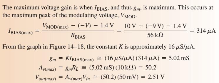
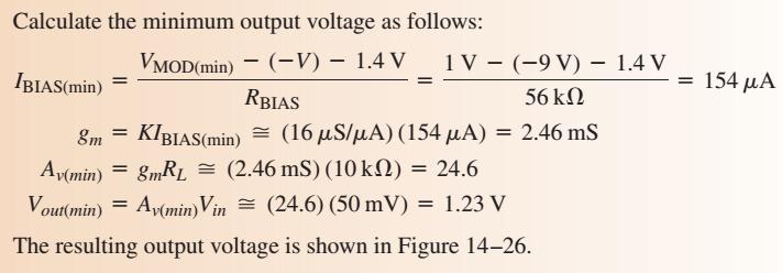
26 The Operational Transconductance Amplifier In an OTA, the transconductance is dependent on a constant (K) times the bias current (I BIAS ). The value of the constant K is dependent on the internal circuit design: g m = K I BIAS A typical relationship of the transconductance and the bias current is illustrated. The transconductance increases linearly with the bias current. The proportionality constant, K, is the slope of the line. In this case, K is approximately 16 μs/μa The output current is controlled by the input voltage and the bias current: I out = g m V in = K I BIAS V in
27 Basic OTA Circuits An OTA used as an inverting amplifier with a fixed voltage gain is shown. The voltage gain is set by the transconductance and the load resistance as follows: The transconductance of the amplifier shown is determined by the amount of bias current, which is set by the dc supply voltages and the bias resistor R BIAS.
28 Basic OTA Circuits The voltage gain can be controlled by the amount of bias current. This can be done manually by using a variable resistor in series with R BIAS.The voltage gain can also be controlled with an externally applied variable voltage.
29 A Specific OTA The LM13700 is a dual device package containing two OTAs and buffer circuits. The maximum dc supply voltages are ± 18 V. The bias current is determined by the following formula: The positive bias voltage, +V BIAS, may be obtained from the positive supply voltage, +V
30 The Operational Transconductance Amplifier Example: The OTA in Figure is connected as an inverting fixed-gain amplifier where +V BIAS = +V. Determine the approximate voltage gain for K = 16 μs/μa.
31 OTA Application: Amplitude Modulator An OTA connected as an amplitude modulator is shown. The voltage gain is varied by applying a modulation voltage to the bias input. When a constant-amplitude input signal is applied, the amplitude of the output signal will vary according to the modulation voltage on the bias input. The gain is dependent on bias current, and bias current is related to the modulation voltage by the following relationship:
32 OTA Application: Amplitude Modulator

33 OTA Application: Amplitude Modulator
34 OTA Application: Amplitude Modulator

35 OTA Application: Amplitude Modulator
36 OTA Application: Schmitt Trigger An OTA connected as a Schmitt trigger is shown. Basically, a Schmitt trigger is a comparator with hysteresis where the input voltage is large enough to drive the device into its saturated states. When the input voltage exceeds a certain threshold value or trigger point, the device switches to one of its saturated output states. When the input falls below another threshold value, the device switches to its other saturated output state.
37 OTA Application: Schmitt Trigger In the case of the OTA Schmitt trigger, the threshold levels are set by the current through resistor R 1.The maximum output current in an OTA equals the bias current. Therefore, in the saturated output states, I out = I BIAS. The maximum positive output voltage is I out R 1 and this voltage is the positive threshold value or upper trigger point. When the input voltage exceeds this value, the output switches to its maximum negative voltage, which is - I out R 1. Since I out = I BIAS, the trigger points can be controlled by the bias current.
38 OTA Application: Schmitt Trigger
39 The Logarithmic Amplifier Log and antilog amplifiers are used in applications that require compression of analog input data, linearization of transducers that have exponential outputs, and analog multiplication and division. They are often used in high-frequency communication systems, including fiber optics, for processing wide dynamic range signals. The semiconductor pn junction in the form of either a diode or the base-emitter junction of a BJT provides a logarithmic characteristic. The diode characteristic curve is shown, where V F is the forward diode voltage and I F is the forward diode current.

40 The Logarithmic Amplifier The current voltage relation is: II FF = II RR ee qqvv FF/kkkk Solving for V F we get: VV FF = kkkk qq ln II FF II RR The output is limited to a maximum value of approximately 0.7 V because the diode s logarithmic characteristic is restricted to voltages below 0.7 V.
41 The Logarithmic Amplifier When a diode is placed in the feedback loop of an op-amp circuit, the output voltage is proportional to the log of the input voltage. From the circuit we have: VV oooooo = VV FF V in I in R 1 0 V I F + + V F Op-amp V out II FF = II iiii = VV iiii RR 1 Substituting into the formula for V F we get: VV oooooo = kkkk qq ln VV iiii II RR RR 1 = (0.025VV) ln VV iiii II RR RR 1 The gain decreases with increasing input voltage; therefore the amplifier is said to compress signals.
42 The Logarithmic Amplifier For the circuit shown, the equation for V out is V out Vin V ln I R ( ) R 1 (I R is a constant for a given diode.) What is V out? (Assume I R = 50 na.) Vout 11 V V ln 50 na 1.0 k ( ) ( )( Ω) V in V in +11 V RI in kω R 1 0 V I F + V F Op-amp + V out out = 307 mv
43 The Logarithmic Amplifier When a BJT is used in the feedback path, the output is referred to the ground of the base connection rather than the virtual ground. This eliminates offset and bias current errors. For the BJT, I EBO (emitter-to-base leakage current) replaces I R in the equation for V out : V out = Vin V ln I R ( ) EBO 1 Log amplifiers are available in IC form with even better performance than the basic log amps shown here. For example, the MAX4206 operates over 5 decades and can measure current from 10 na to 1 ma. V in I in R 1 I C + 0 V Op-amp + V BE V out
44 The Antilog Amplifier An antilog amplifier is formed by connecting a transistor (or diode) as the input element as shown. We have: VV oooooo = RR ff II CC, II CC = II EEEE0 ee qqvv BBBB/kkkk VV oooooo = RR ff II EEEE0 ee qqvv BBBB/kkkk The equation for V out for the basic BJT antilog amp is: V out = RI f V in EBO antilog 25 mv IC antilog amps are also available. For example, the Datel LA-8048 is a log amp and the Datel LA-8049 is its counterpart antilog amp. These ICs are specified for a six decade range. V in + V BE I C 0 V + R f Op-amp + V out
45 The Antilog Amplifier EXAMPLE: For the antilog amplifier in Figure, find the output voltage. Assume I EBO = 40 na. V out antilog Vin = RI f EBO = -3 V. 25 mv
46 Constant-Current Source A constant-current source delivers a load current that remains constant when the load resistance changes. From the figure we get: II LL = II ii = VV IIII RR ii If R L changes, I L remains constant as long as V IN and R i are held constant I L = I i V IN + R i I i 0 V 0 A + R L Constant-current source
47 Current-to-Voltage Converter A current-to-voltage converter converts a variable input current to a proportional output voltage. A basic circuit that accomplishes this is shown. From the figure we get: VV oooooo = II ii RR ff R f I i I i 0 V + V out Current-to-voltage converter
48 Voltage-to-Current Converter A basic voltage-to-current converter is shown. This circuit is used in applications where it is necessary to have an output (load) current that is controlled by an input voltage. From the figure we get: II LL = VV iiii RR 1 V in + I = 0 I L R L I 1 R 1 Voltage-to-current converter
49 Peak Detector This circuit is used to detect the peak of the input voltage and store that peak voltage on a capacitor. When a positive voltage is applied to the noninverting input of the op-amp, the high-level output voltage of the op-amp forwardbiases the diode and charges the capacitor. The capacitor continues to charge until its voltage reaches a value equal to the input voltage and thus both op-amp inputs are at the same voltage. At this point, the op-amp comparator switches, and its output goes to the low level. The diode is now reverse biased, and the capacitor stops charging. If a greater input peak occurs, the capacitor charges to the new peak R i V in + R 1 Peak detector C V out
50 Selected Key Terms Instrumentation An amplifier used for amplifying small amplifier signals riding on large common-mode voltages. Isolation amplifier Operational transconductance amplifier Transconductance An amplifier with electrically isolated internal stages. A voltage-to-current amplifier. In an electronic device, the ratio of the output current to the input voltage.
51 Quiz 1. A typical instrumentation amplifier has a. high CMRR b. unity gain c. low input impedance d. all of the above
52 Quiz 2. When an instrumentation amplifier uses guarding, the shield is driven by a a. low-impedance differential source b. low-impedance common-mode source c. high-impedance differential source d. high-impedance common-mode source
53 Quiz 3. You can achieve a higher bandwidth for an instrumentation amplifier if you a. use guarding b. use a larger gain setting resistor c. capacitively couple the input signal d. none of the above
54 Quiz 4. An application where an isolation amplifier is particularly useful is when a. the input signal has very large dynamic range b. control of the frequency response is necessary c. voltages could present a hazard d. all of the above
55 Quiz 5. For an OTA, the gain is determined by a. a ratio of two resistors b. bias current c. a single gain setting resistor d. the amplitude of the input signal
56 Quiz 6. Transconductance is the ratio of a. output current to input voltage b. input current to output voltage c. output resistance to input resistance d. output voltage to input current
57 Quiz 7. A circuit that is useful for signal compression is a a. instrumentation amplifier b. OTA c. logarithmic amplifier d. antilog amplifier
58 Quiz 8. The circuit shown here is a a. peak detector b. current-to-voltage converter c. voltage-to-current converter d. isolation amplifier V in + I = 0 I L R L I 1 R 1
59 Quiz 9. The circuit shown here is a a. current-to-voltage converter b. constant current source c. logarithmic amplifier d. antilog amp V in + V BE I C + R f 0 V Op-amp V out +
60 Quiz 10. The circuit shown here is a a. current-to-voltage converter b. voltage-to-current converter c. constant current source d. peak detector V in + R i R 1 V out C
61 Quiz Answers: 1. a 6. a 2. b 7. c 3. d 8. c 4. c 9. d 5. b 10. d
Lecture #4 Special-purpose Op-amp Circuits
 Spring 2015 Benha University Faculty of Engineering at Shoubra ECE-322 Electronic Circuits (B) Lecture #4 Special-purpose Op-amp Circuits Instructor: Dr. Ahmad El-Banna Agenda Instrumentation Amplifiers
IFB270 Advanced Electronic Circuits
 IFB270 Advanced Electronic Circuits Chapter 14: Special-purpose op-amp circuits Prof. Manar Mohaisen Department of EEC Engineering eview of the Precedent Lecture Introduce the level detection op-amp circuits
Analog Electronics. Lecture. Op-amp Circuits and Active Filters. Muhammad Amir Yousaf
 Analog Electronics Lecture Op-amp Circuits and Active Filters Muhammad Amir Yousaf Instrumentation Amplifiers An instrumentation amplifier (IA) amplifies the voltage difference between its terminals. It
Analog Circuits Part 3 Operational Amplifiers
 Introductory Medical Device Prototyping Analog Circuits Part 3 Operational Amplifiers, http://saliterman.umn.edu/ Department of Biomedical Engineering, University of Minnesota Concepts to be Reviewed Operational
Unit WorkBook 1 Level 4 ENG U22 Electronic Circuits and Devices 2018 UniCourse Ltd. All Rights Reserved. Sample
 Pearson BTEC Level 4 Higher Nationals in Engineering (RQF) Unit 22: Electronic Circuits and Devices Unit Workbook 1 in a series of 4 for this unit Learning Outcome 1 Operational Amplifiers Page 1 of 23
Basic Operational Amplifier Circuits
 Basic Operational Amplifier Circuits Comparators A comparator is a specialized nonlinear op-amp circuit that compares two input voltages and produces an output state that indicates which one is greater.
Concepts to be Reviewed
 Introductory Medical Device Prototyping Analog Circuits Part 3 Operational Amplifiers, http://saliterman.umn.edu/ Department of Biomedical Engineering, University of Minnesota Concepts to be Reviewed Operational
Gechstudentszone.wordpress.com
 8.1 Operational Amplifier (Op-Amp) UNIT 8: Operational Amplifier An operational amplifier ("op-amp") is a DC-coupled high-gain electronic voltage amplifier with a differential input and, usually, a single-ended
Operational Amplifier BME 360 Lecture Notes Ying Sun
 Operational Amplifier BME 360 Lecture Notes Ying Sun Characteristics of Op-Amp An operational amplifier (op-amp) is an analog integrated circuit that consists of several stages of transistor amplification
Lesson number one. Operational Amplifier Basics
 What About Lesson number one Operational Amplifier Basics As well as resistors and capacitors, Operational Amplifiers, or Op-amps as they are more commonly called, are one of the basic building blocks
Homework Assignment 03
 Homework Assignment 03 Question 1 (Short Takes), 2 points each unless otherwise noted. 1. Two 0.68 μf capacitors are connected in series across a 10 khz sine wave signal source. The total capacitive reactance
Introduction to Analog Interfacing. ECE/CS 5780/6780: Embedded System Design. Various Op Amps. Ideal Op Amps
 Introduction to Analog Interfacing ECE/CS 5780/6780: Embedded System Design Scott R. Little Lecture 19: Operational Amplifiers Most embedded systems include components that measure and/or control real-world
Analog Electronics. Lecture Pearson Education. Upper Saddle River, NJ, All rights reserved.
 Analog Electronics V Lecture 5 V Operational Amplifers Op-amp is an electronic device that amplify the difference of voltage at its two inputs. V V 8 1 DIP 8 1 DIP 20 SMT 1 8 1 SMT Operational Amplifers
LM13600 Dual Operational Transconductance Amplifiers with Linearizing Diodes and Buffers
 LM13600 Dual Operational Transconductance Amplifiers with Linearizing Diodes and Buffers General Description The LM13600 series consists of two current controlled transconductance amplifiers each with
UNIT I. Operational Amplifiers
 UNIT I Operational Amplifiers Operational Amplifier: The operational amplifier is a direct-coupled high gain amplifier. It is a versatile multi-terminal device that can be used to amplify dc as well as
Summer 2015 Examination
 Summer 2015 Examination Subject Code: 17445 Model Answer Important Instructions to examiners: 1) The answers should be examined by key words and not as word-to-word as given in the model answer scheme.
Operational amplifiers
 Operational amplifiers Bởi: Sy Hien Dinh INTRODUCTION Having learned the basic laws and theorems for circuit analysis, we are now ready to study an active circuit element of paramount importance: the operational
Linear IC s and applications
 Questions and Solutions PART-A Unit-1 INTRODUCTION TO OP-AMPS 1. Explain data acquisition system Jan13 DATA ACQUISITION SYSYTEM BLOCK DIAGRAM: Input stage Intermediate stage Level shifting stage Output
Instrumentation amplifier
 Instrumentationamplifieris a closed-loop gainblock that has a differential input and an output that is single-ended with respect to a reference terminal. Application: are intended to be used whenever acquisition
UNIT - 1 OPERATIONAL AMPLIFIER FUNDAMENTALS
 UNIT - 1 OPERATIONAL AMPLIFIER FUNDAMENTALS 1.1 Basic operational amplifier circuit- hte basic circuit of an operational amplifier is as shown in above fig. has a differential amplifier input stage and
2. The. op-amp in and 10K. (a) 0 Ω. (c) 0.2% (d) (a) 0.02K. (b) 4. The. 5 V, then. 0V (virtual. (a) (c) Fall V. (d) V.
 0 Ω. (c) 0.2% (d) (a) 0.02K. (b) 4. The. 5 V, then. 0V (virtual. (a) (c) Fall V. (d) V.") Homework Assignment 04 Question 1 (2 points each unless noted otherwise) 1. A 9-V dc power supply generates 10 W in a resistor. What peak-to-peak amplitude should an ac source have to generate the same
Homework Assignment 04 Question 1 (2 points each unless noted otherwise) 1. A 9-V dc power supply generates 10 W in a resistor. What peak-to-peak amplitude should an ac source have to generate the same
tyuiopasdfghjklzxcvbnmqwertyuiopas dfghjklzxcvbnmqwertyuiopasdfghjklzx cvbnmqwertyuiopasdfghjklzxcvbnmq
 qwertyuiopasdfghjklzxcvbnmqwertyui opasdfghjklzxcvbnmqwertyuiopasdfgh jklzxcvbnmqwertyuiopasdfghjklzxcvb nmqwertyuiopasdfghjklzxcvbnmqwer Instrumentation Device Components Semester 2 nd tyuiopasdfghjklzxcvbnmqwertyuiopas
LINEAR IC APPLICATIONS
 1 B.Tech III Year I Semester (R09) Regular & Supplementary Examinations December/January 2013/14 1 (a) Why is R e in an emitter-coupled differential amplifier replaced by a constant current source? (b)
Differential Amplifier : input. resistance. Differential amplifiers are widely used in engineering instrumentation
 Differential Amplifier : input resistance Differential amplifiers are widely used in engineering instrumentation Differential Amplifier : input resistance v 2 v 1 ir 1 ir 1 2iR 1 R in v 2 i v 1 2R 1 Differential
OPERATIONAL AMPLIFIER PREPARED BY, PROF. CHIRAG H. RAVAL ASSISTANT PROFESSOR NIRMA UNIVRSITY
 OPERATIONAL AMPLIFIER PREPARED BY, PROF. CHIRAG H. RAVAL ASSISTANT PROFESSOR NIRMA UNIVRSITY INTRODUCTION Op-Amp means Operational Amplifier. Operational stands for mathematical operation like addition,
LM13700 Dual Operational Transconductance Amplifiers with Linearizing Diodes and Buffers
 LM13700 Dual Operational Transconductance Amplifiers with Linearizing Diodes and Buffers General Description The LM13700 series consists of two current controlled transconductance amplifiers, each with
Dimensions in inches (mm) .268 (6.81).255 (6.48) .390 (9.91).379 (9.63) .045 (1.14).030 (.76) 4 Typ. Figure 1. Typical application circuit.
 .268 (6.81).255 (6.48) .390 (9.91).379 (9.63) .045 (1.14).030 (.76) 4 Typ. Figure 1. Typical application circuit.") LINEAR OPTOCOUPLER FEATURES Couples AC and DC signals.% Servo Linearity Wide Bandwidth, > KHz High Gain Stability, ±.%/C Low Input-Output Capacitance Low Power Consumption, < mw Isolation Test Voltage,
LINEAR OPTOCOUPLER FEATURES Couples AC and DC signals.% Servo Linearity Wide Bandwidth, > KHz High Gain Stability, ±.%/C Low Input-Output Capacitance Low Power Consumption, < mw Isolation Test Voltage,
TRANSDUCER INTERFACE APPLICATIONS
 TRANSDUCER INTERFACE APPLICATIONS Instrumentation amplifiers have long been used as preamplifiers in transducer applications. High quality transducers typically provide a highly linear output, but at a
CHARACTERIZATION OF OP-AMP
 EXPERIMENT 4 CHARACTERIZATION OF OP-AMP OBJECTIVES 1. To sketch and briefly explain an operational amplifier circuit symbol and identify all terminals. 2. To list the amplifier stages in a typical op-amp
GATE SOLVED PAPER - IN
 YEAR 202 ONE MARK Q. The i-v characteristics of the diode in the circuit given below are : v -. A v 0.7 V i 500 07 $ = * 0 A, v < 0.7 V The current in the circuit is (A) 0 ma (C) 6.67 ma (B) 9.3 ma (D)
Q1. Explain the Astable Operation of multivibrator using 555 Timer IC.
 Q1. Explain the Astable Operation of multivibrator using 555 Timer I. Answer: The following figure shows the 555 Timer connected for astable operation. A V PIN 8 PIN 7 B 5K PIN6 - S Q 5K PIN2 - Q PIN3
HOME ASSIGNMENT. Figure.Q3
 HOME ASSIGNMENT 1. For the differential amplifier circuit shown below in figure.q1, let I=1 ma, V CC =5V, v CM = -2V, R C =3kΩ and β=100. Assume that the BJTs have v BE =0.7 V at i C =1 ma. Find the voltage
Dimensions in inches (mm) .021 (0.527).035 (0.889) .016 (.406).020 (.508 ) .280 (7.112).330 (8.382) Figure 1. Typical application circuit.
 .021 (0.527).035 (0.889) .016 (.406).020 (.508 ) .280 (7.112).330 (8.382) Figure 1. Typical application circuit.") IL Linear Optocoupler Dimensions in inches (mm) FEATURES Couples AC and DC signals.% Servo Linearity Wide Bandwidth, > khz High Gain Stability, ±.%/C Low Input-Output Capacitance Low Power Consumption,
IL Linear Optocoupler Dimensions in inches (mm) FEATURES Couples AC and DC signals.% Servo Linearity Wide Bandwidth, > khz High Gain Stability, ±.%/C Low Input-Output Capacitance Low Power Consumption,
About the Tutorial. Audience. Prerequisites. Copyright & Disclaimer. Linear Integrated Circuits Applications
 About the Tutorial Linear Integrated Circuits are solid state analog devices that can operate over a continuous range of input signals. Theoretically, they are characterized by an infinite number of operating
EE 368 Electronics Lab. Experiment 10 Operational Amplifier Applications (2)
") EE 368 Electronics Lab Experiment 10 Operational Amplifier Applications (2) 1 Experiment 10 Operational Amplifier Applications (2) Objectives To gain experience with Operational Amplifier (Op-Amp). To
EE 368 Electronics Lab Experiment 10 Operational Amplifier Applications (2) 1 Experiment 10 Operational Amplifier Applications (2) Objectives To gain experience with Operational Amplifier (Op-Amp). To
ELT 215 Operational Amplifiers (LECTURE) Chapter 5
 Chapter 5") CHAPTER 5 Nonlinear Signal Processing Circuits INTRODUCTION ELT 215 Operational Amplifiers (LECTURE) In this chapter, we shall present several nonlinear circuits using op-amps, which include those situations
CHAPTER 5 Nonlinear Signal Processing Circuits INTRODUCTION ELT 215 Operational Amplifiers (LECTURE) In this chapter, we shall present several nonlinear circuits using op-amps, which include those situations
EE LINEAR INTEGRATED CIRCUITS & APPLICATIONS
 UNITII CHARACTERISTICS OF OPAMP 1. What is an opamp? List its functions. The opamp is a multi terminal device, which internally is quite complex. It is a direct coupled high gain amplifier consisting of
Analog Electronic Circuits Code: EE-305-F
 Analog Electronic Circuits Code: EE-305-F 1 INTRODUCTION Usually Called Op Amps Section -C Operational Amplifier An amplifier is a device that accepts a varying input signal and produces a similar output
Voltage-to-Frequency and Frequency-to-Voltage Converter ADVFC32
 a FEATURES High Linearity 0.01% max at 10 khz FS 0.05% max at 100 khz FS 0.2% max at 500 khz FS Output TTL/CMOS Compatible V/F or F/V Conversion 6 Decade Dynamic Range Voltage or Current Input Reliable
Op-Amp Simulation Part II
 Op-Amp Simulation Part II EE/CS 5720/6720 This assignment continues the simulation and characterization of a simple operational amplifier. Turn in a copy of this assignment with answers in the appropriate
EE 3305 Lab I Revised July 18, 2003
 Operational Amplifiers Operational amplifiers are high-gain amplifiers with a similar general description typified by the most famous example, the LM741. The LM741 is used for many amplifier varieties
1) Consider the circuit shown in figure below. Compute the output waveform for an input of 5kHz
 Consider the circuit shown in figure below. Compute the output waveform for an input of 5kHz") ) Consider the circuit shown in figure below. Compute the output waveform for an input of 5kHz Solution: a) Input is of constant amplitude of 2 V from 0 to 0. ms and 2 V from 0. ms to 0.2 ms. The output
) Consider the circuit shown in figure below. Compute the output waveform for an input of 5kHz Solution: a) Input is of constant amplitude of 2 V from 0 to 0. ms and 2 V from 0. ms to 0.2 ms. The output
DMI COLLEGE OF ENGINEERING
 DMI COLLEGE OF ENGINEERING DEPARTMENT OF ELECTRONICS & COMMUNICATION ENGINEERING EC8453 - LINEAR INTEGRATED CIRCUITS Question Bank (II-ECE) UNIT I BASICS OF OPERATIONAL AMPLIFIERS PART A 1.Mention the
Difference between BJTs and FETs. Junction Field Effect Transistors (JFET)
") Difference between BJTs and FETs Transistors can be categorized according to their structure, and two of the more commonly known transistor structures, are the BJT and FET. The comparison between BJTs
Difference between BJTs and FETs Transistors can be categorized according to their structure, and two of the more commonly known transistor structures, are the BJT and FET. The comparison between BJTs
AN-1106 Custom Instrumentation Amplifier Design Author: Craig Cary Date: January 16, 2017
 AN-1106 Custom Instrumentation Author: Craig Cary Date: January 16, 2017 Abstract This application note describes some of the fine points of designing an instrumentation amplifier with op-amps. We will
Lecture #4 Basic Op-Amp Circuits
 Summer 2015 Ahmad El-Banna Faculty of Engineering Department of Electronics and Communications GEE336 Electronic Circuits II Lecture #4 Basic Op-Amp Circuits Instructor: Dr. Ahmad El-Banna Agenda Some
AD8232 EVALUATION BOARD DOCUMENTATION
 One Technology Way P.O. Box 9106 Norwood, MA 02062-9106 Tel: 781.329.4700 Fax: 781.461.3113 www.analog.com AD8232 EVALUATION BOARD DOCUMENTATION FEATURES Ready to use Heart Rate Monitor (HRM) Front end
Chapter 10: The Operational Amplifiers
 Chapter 10: The Operational Amplifiers Electronic Devices Operational Amplifiers (op-amp) Op-amp is an electronic device that amplify the difference of voltage at its two inputs. It has two input terminals,
BIOMEDICAL INSTRUMENTATION PROBLEM SHEET 1
 BIOMEDICAL INSTRUMENTATION PROBLEM SHEET 1 Dr. Gari Clifford Hilary Term 2013 1. (Exemplar Finals Question) a) List the five vital signs which are most commonly recorded from patient monitors in high-risk
Homework Assignment 04
 Question 1 (Short Takes) Homework Assignment 04 1. Consider the single-supply op-amp amplifier shown. What is the purpose of R 3? (1 point) Answer: This compensates for the op-amp s input bias current.
Instrumentation Amplifiers Filters Integrators Differentiators Frequency-Gain Relation Non-Linear Op-Amp Applications DC Imperfections
 Lecture Op-Amp Building Blocks and Applications Instrumentation Amplifiers Filters Integrators Differentiators Frequency-Gain elation Non-Linear Op-Amp Applications DC Imperfections ELG439 Check List for
Document Name: Electronic Circuits Lab. Facebook: Twitter:
 Document Name: Electronic Circuits Lab www.vidyathiplus.in Facebook: www.facebook.com/vidyarthiplus Twitter: www.twitter.com/vidyarthiplus Copyright 2011-2015 Vidyarthiplus.in (VP Group) Page 1 CIRCUIT
Electronics Lab. (EE21338)
") Princess Sumaya University for Technology The King Abdullah II School for Engineering Electrical Engineering Department Electronics Lab. (EE21338) Prepared By: Eng. Eyad Al-Kouz October, 2012 Table of
Princess Sumaya University for Technology The King Abdullah II School for Engineering Electrical Engineering Department Electronics Lab. (EE21338) Prepared By: Eng. Eyad Al-Kouz October, 2012 Table of
LM13700 Dual Operational Transconductance Amplifiers with Linearizing Diodes and Buffers
 LM13700 Dual Operational Transconductance Amplifiers with Linearizing Diodes and Buffers General Description The LM13700 series consists of two current controlled transconductance amplifiers, each with
Model 176 and 178 DC Amplifiers
 Model 176 and 178 DC mplifiers Features*! Drifts to 100 MΩ! CMR: 120 db @! Gain Linearity of ±.005% *The key features of this amplifier series, listed above, do not necessarily apply
Operational Amplifier as A Black Box
 Chapter 8 Operational Amplifier as A Black Box 8. General Considerations 8.2 Op-Amp-Based Circuits 8.3 Nonlinear Functions 8.4 Op-Amp Nonidealities 8.5 Design Examples Chapter Outline CH8 Operational Amplifier
UNIVERSITY OF NORTH CAROLINA AT CHARLOTTE Department of Electrical and Computer Engineering
 UNIVERSITY OF NORTH CAROLINA AT CHARLOTTE Department of Electrical and Computer Engineering EXPERIMENT 5 GAIN-BANDWIDTH PRODUCT AND SLEW RATE OBJECTIVES In this experiment the student will explore two
the reactance of the capacitor, 1/2πfC, is equal to the resistance at a frequency of 4 to 5 khz.
 EXPERIMENT 12 INTRODUCTION TO PSPICE AND AC VOLTAGE DIVIDERS OBJECTIVE To gain familiarity with PSPICE, and to review in greater detail the ac voltage dividers studied in Experiment 14. PROCEDURE 1) Connect
ECET DAQ & Control Systems
 1 Electrical Engineering Technology ECET 17700 DAQ & Control Systems Lecture # 11 Inverting Amplifier & Summer Professors Robert Herrick & J. Michael Jacob Purdue University ECET 17700 DAQ & Systems Control
ES250: Electrical Science. HW6: The Operational Amplifier
 ES250: Electrical Science HW6: The Operational Amplifier Introduction This chapter introduces the operational amplifier or op amp We will learn how to analyze and design circuits that contain op amps,
Operational Amplifiers
 Operational Amplifiers Table of contents 1. Design 1.1. The Differential Amplifier 1.2. Level Shifter 1.3. Power Amplifier 2. Characteristics 3. The Opamp without NFB 4. Linear Amplifiers 4.1. The Non-Inverting
GATE: Electronics MCQs (Practice Test 1 of 13)
") GATE: Electronics MCQs (Practice Test 1 of 13) 1. Removing bypass capacitor across the emitter leg resistor in a CE amplifier causes a. increase in current gain b. decrease in current gain c. increase
GATE: Electronics MCQs (Practice Test 1 of 13) 1. Removing bypass capacitor across the emitter leg resistor in a CE amplifier causes a. increase in current gain b. decrease in current gain c. increase
55:041 Electronic Circuits
 55:041 Electronic Circuits Reiew of Op-Amps Sections of Chapters 9 & 14 A. Kruger Op-Amp Reiew-1 Real-World Op-Amp In earlier courses, op-amp were often considered ideal Infinite input resistance Infinite
ELC224 Final Review (12/10/2009) Name:
 Name:") ELC224 Final Review (12/10/2009) Name: Select the correct answer to the problems 1 through 20. 1. A common-emitter amplifier that uses direct coupling is an example of a dc amplifier. 2. The frequency
ELC224 Final Review (12/10/2009) Name: Select the correct answer to the problems 1 through 20. 1. A common-emitter amplifier that uses direct coupling is an example of a dc amplifier. 2. The frequency
ELEC207 LINEAR INTEGRATED CIRCUITS
 Concept of VIRTUAL SHORT For feedback amplifiers constructed with op-amps, the two op-amp terminals will always be approximately equal (V + = V - ) This condition in op-amp feedback amplifiers is known
Operational Amplifiers
 Basic Electronics Syllabus: Introduction to : Ideal OPAMP, Inverting and Non Inverting OPAMP circuits, OPAMP applications: voltage follower, addition, subtraction, integration, differentiation; Numerical
UNIVERSITY OF UTAH ELECTRICAL AND COMPUTER ENGINEERING DEPARTMENT ELECTROMYOGRAM (EMG) DETECTOR WITH AUDIOVISUAL OUTPUT
 DETECTOR WITH AUDIOVISUAL OUTPUT") UNIVESITY OF UTAH ELECTICAL AND COMPUTE ENGINEEING DEPATMENT ECE 3110 LABOATOY EXPEIMENT NO. 5 ELECTOMYOGAM (EMG) DETECTO WITH AUDIOVISUAL OUTPUT Pre-Lab Assignment: ead and review Sections 2.4, 2.8.2,
UNIVESITY OF UTAH ELECTICAL AND COMPUTE ENGINEEING DEPATMENT ECE 3110 LABOATOY EXPEIMENT NO. 5 ELECTOMYOGAM (EMG) DETECTO WITH AUDIOVISUAL OUTPUT Pre-Lab Assignment: ead and review Sections 2.4, 2.8.2,
IFB270 Advanced Electronic Circuits
 IFB270 Advanced Electronic Circuits Chapter 12: The operational amplifier Prof. Manar Mohaisen Department of EEC Engineering Review of the Precedent Lecture Introduce the four layer diode Introduce the
Analog Circuits Part 2 Semiconductors
 Introductory Medical Device Prototyping Analog Circuits Part 2 Semiconductors, http://saliterman.umn.edu/ Department of Biomedical Engineering, University of Minnesota Concepts to be Covered Semiconductors
Examining a New In-Amp Architecture for Communication Satellites
 White Paper Examining a New In-Amp Architecture for Communication Satellites Introduction With more 500 conventional sensors monitoring the condition and performance of various subsystems on a medium sized
ECE-342 Test 1: Sep 27, :00-8:00, Closed Book. Name : SOLUTION
 ECE-342 Test 1: Sep 27, 2011 6:00-8:00, Closed Book Name : SOLUTION All solutions must provide units as appropriate. Use the physical constants and data as provided on the formula sheet the last page of
Testing and Stabilizing Feedback Loops in Today s Power Supplies
 Keywords Venable, frequency response analyzer, impedance, injection transformer, oscillator, feedback loop, Bode Plot, power supply design, open loop transfer function, voltage loop gain, error amplifier,
Emitter Coupled Differential Amplifier
 Emitter Coupled Differential Amplifier Returning to the transistor, a very common and useful circuit is the differential amplifier. It's basic circuit is: Vcc Q1 Q2 Re Vee To see how this circuit works,
DEPARTMENT OF ELECTRICAL ENGINEERING AND COMPUTER SCIENCE MASSACHUSETTS INSTITUTE OF TECHNOLOGY CAMBRIDGE, MASSACHUSETTS 02139
 DEPARTMENT OF ELECTRICAL ENGINEERING AND COMPUTER SCIENCE MASSACHUSETTS INSTITUTE OF TECHNOLOGY CAMBRIDGE, MASSACHUSETTS 019.101 Introductory Analog Electronics Laboratory Laboratory No. READING ASSIGNMENT
OBSOLETE. High Performance, BiFET Operational Amplifiers AD542/AD544/AD547 REV. B
 a FEATURES Ultralow Drift: 1 V/ C (AD547L) Low Offset Voltage: 0.25 mv (AD547L) Low Input Bias Currents: 25 pa max Low Quiescent Current: 1.5 ma Low Noise: 2 V p-p High Open Loop Gain: 110 db High Slew
 VALLIAMMAI ENGINEERING COLLEGE SRM Nagar, Kattankulathur 603 203. DEPARTMENT OF ELECTRONICS & COMMUNICATION ENGINEERING QUESTION BANK SUBJECT : EC6404 LINEAR INTEGRATED CIRCUITS SEM / YEAR: IV / II year
Chapter 6. BJT Amplifiers
 Basic Electronic Devices and Circuits EE 111 Electrical Engineering Majmaah University 2 nd Semester 1432/1433 H Chapter 6 BJT Amplifiers 1 Introduction The things you learned about biasing a transistor
Single Supply, Rail to Rail Low Power FET-Input Op Amp AD820
 a FEATURES True Single Supply Operation Output Swings Rail-to-Rail Input Voltage Range Extends Below Ground Single Supply Capability from + V to + V Dual Supply Capability from. V to 8 V Excellent Load
PHYS 3152 Methods of Experimental Physics I E2. Diodes and Transistors 1
 Part I Diodes Purpose PHYS 3152 Methods of Experimental Physics I E2. In this experiment, you will investigate the current-voltage characteristic of a semiconductor diode and examine the applications of
Chapter 11. Differential Amplifier Circuits
 Chapter 11 Differential Amplifier Circuits 11.0 ntroduction Differential amplifier or diff-amp is a multi-transistor amplifier. t is the fundamental building block of analog circuit. t is virtually formed
LM2900 LM3900 LM3301 Quad Amplifiers
 LM2900 LM3900 LM3301 Quad Amplifiers General Description The LM2900 series consists of four independent dual input internally compensated amplifiers which were designed specifically to operate off of a
Experiments #7. Operational Amplifier part 1
 Experiments #7 Operational Amplifier part 1 1) Objectives: The objective of this lab is to study operational amplifier (op amp) and its applications. We will be simulating and building some basic op-amp
Glossary + - A BNC plug that shorts the inner wire in a coax cable to the outer shield through a
 50Ω Terminator AC Active Alligator Clip Back Bias Base Battery Bias + - Bipolar Transistor BJT Black Box BNC BNC Cable A BNC plug that shorts the inner wire in a coax cable to the outer shield through
GOVERNMENT OF KARNATAKA KARNATAKA STATE PRE-UNIVERSITY EDUCATION EXAMINATION BOARD II YEAR PUC EXAMINATION JULY-2012 SCHEME OF VALUATION
 GOVERNMENT OF KARNATAKA KARNATAKA STATE PRE-UNIVERSITY EDUCATION EXAMINATION BOARD II YEAR PUC EXAMINATION JULY-0 SCHEME OF VALUATION Subject Code: 40 Subject: PART - A 0. Which region of the transistor
INTEGRATED CIRCUITS. AN145 NE5517/A transconductance amplifier applications Dec
 INTEGRATED CIRCUITS NE5517/A transconductance amplifier applications 1988 Dec Application note DESCRIPTION The Philips Semiconductors NE5517 is a truly versatile dual operational transconductance amplifier.
Lecture 4. Integrated Electronics
 Lecture 4 Integrated Electronics P, N is the doping of silicon to carry P (+) or N (-) charge) DIODES -> Recitifier I P N If V > V ON of diode, V V ON I = R Forward bias, conducting I Von ~ 0.6 V Example:
Single Supply, Rail to Rail Low Power FET-Input Op Amp AD820
 a FEATURES True Single Supply Operation Output Swings Rail-to-Rail Input Voltage Range Extends Below Ground Single Supply Capability from V to V Dual Supply Capability from. V to 8 V Excellent Load Drive
Homework Assignment 06
 Question 1 (2 points each unless noted otherwise) Homework Assignment 06 1. True or false: when transforming a circuit s diagram to a diagram of its small-signal model, we replace dc constant current sources
ECE:3410 Electronic Circuits
 ECE:3410 Electronic Circuits Reiew of Op-Amps Sections of Chapters 9 & 14 A. Kruger Op-Amp Reiew-1 Real-World Op-Amp In earlier courses, op-amp were often considered ideal Infinite input resistance Infinite
GLOSSARY. A connector used to T together two BNC coax cables and a BNC jack. The transfer function vs. frequency plotted on Log Log axis.
 GLOSSARY 50ΩTerminator AC Active Alligator Clip Back Bias Base Battery Bias + - Bipolar Transistor BJT Black Box BNC BNC Cable A BNC plug that shorts the inner wire in a coax cable to the outer shield
Chapter 5. Operational Amplifiers and Source Followers. 5.1 Operational Amplifier
 Chapter 5 Operational Amplifiers and Source Followers 5.1 Operational Amplifier In single ended operation the output is measured with respect to a fixed potential, usually ground, whereas in double-ended
LESSON PLAN. SUBJECT: LINEAR IC S AND APPLICATION NO OF HOURS: 52 FACULTY NAME: Mr. Lokesh.L, Hema. B DEPT: ECE. Portions to be covered
 LESSON PLAN SUBJECT: LINEAR IC S AND APPLICATION SUB CODE: 15EC46 NO OF HOURS: 52 FACULTY NAME: Mr. Lokesh.L, Hema. B DEPT: ECE Class# Chapter title/reference literature Portions to be covered MODULE I
Advanced Measurements
 Albaha University Faculty of Engineering Mechanical Engineering Department Lecture 9: Wheatstone Bridge and Filters Ossama Abouelatta o_abouelatta@yahoo.com Mechanical Engineering Department Faculty of
LM148/LM248/LM348 Quad 741 Op Amps
 Quad 741 Op Amps General Description The LM148 series is a true quad 741. It consists of four independent, high gain, internally compensated, low power operational amplifiers which have been designed to
Section 4: Operational Amplifiers
 Section 4: Operational Amplifiers Op Amps Integrated circuits Simpler to understand than transistors Get back to linear systems, but now with gain Come in various forms Comparators Full Op Amps Differential
Micropower, Single-Supply, Rail-to-Rail, Precision Instrumentation Amplifiers MAX4194 MAX4197
 General Description The is a variable-gain precision instrumentation amplifier that combines Rail-to-Rail single-supply operation, outstanding precision specifications, and a high gain bandwidth. This
E40M. Instrumentation Amps and Noise. M. Horowitz, J. Plummer, R. Howe 1
 E40M Instrumentation Amps and Noise M. Horowitz, J. Plummer, R. Howe 1 ECG Lab - Electrical Picture Signal amplitude 1 mv Noise level will be significant will need to amplify and filter We ll use filtering
Lecture #2 Operational Amplifiers
 Spring 2015 Benha University Faculty of Engineering at Shoubra ECE-322 Electronic Circuits (B) Lecture #2 Operational Amplifiers Instructor: Dr. Ahmad El-Banna Agenda Introduction Op-Amps Input Modes and
PURPOSE: NOTE: Be sure to record ALL results in your laboratory notebook.
 EE4902 Lab 9 CMOS OP-AMP PURPOSE: The purpose of this lab is to measure the closed-loop performance of an op-amp designed from individual MOSFETs. This op-amp, shown in Fig. 9-1, combines all of the major
4. Differential Amplifiers. Electronic Circuits. Prof. Dr. Qiuting Huang Integrated Systems Laboratory
 4. Differential Amplifiers Electronic Circuits Prof. Dr. Qiuting Huang Integrated Systems Laboratory Differential Signaling Basics and Motivation Transmitting information with two complementary signals