FFDM -FCRm QC Requirements- What You REALLY Need to Know
|
|
|
- Vivien Long
- 6 years ago
- Views:
Transcription
1 FFDM -FCRm QC Requirements- What You REALLY Need to Know Melissa C. Martin, M.S., FACR, FAAPM, FACMP AAPM Annual Meeting July 28, 2008
2 FDA Approval for Mammography Fuji FCRm System approved for Mammography on July 10, 2006 by the FDA as a FFDM Digital Mammography System

3 CR Technology Protective Layer Photo-stimuable phosphor layer Support J. Ed Barnes, Ph.D. - MTMI
4 Fuji Mammo CR Pixel size 50 micron Use dual sided reading to DQE Imaging Plate has thicker phosphor layer Results in 40-50% increase in NEQ (DQE) Post processing enhances image (e.g. filtering to recognize and enhance calcifications) J. Ed Barnes, Ph.D. - MTMI
5 FCM J. Ed Barnes, Ph.D. - MTMI


 Dual")
6 Enlarged Images 1mm Standard System (100 micron pixel) 1mm J. Ed Barnes, Ph.D. - MTMI FCRm (50 micron pixel) Dual side scan


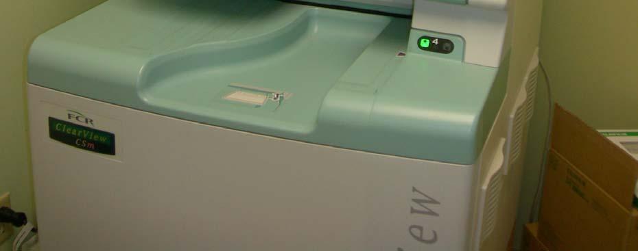
7 Fuji System Components Breast Imaging Review Station ClearView-CSm ClearView-1m Flash Plus IIPm J. Ed Barnes, Ph.D. - MTMI
8 Fuji Clearview CSm Reader Four cassette stacker Processes 20 screening exams/hour (or 100 CR plates/hour) Multi-objective Frequency Processing (MFP) (enhances dense/peripheral tissue) Pattern Enhancement Processing for Mammography (PEM) (enhances calcifications) J. Ed Barnes, Ph.D., - MTMI
9 Other CR Mammography Venders - World Wide Agfa Kodak Konica Canon J. Ed Barnes, Ph.D. - MTMI
10 Kodak Mammography CR Single sided plate Thinner phosphor layer (improves resolution, reduces DQE) Phosphor grain smaller and homogenous BaFBr:Eu phospor 48.5 micron pixel Read out speed reduced Twice as slow Increases SNR Use conventional reader (modified) J. Ed Barnes, Ph.D. - MTMI
11 Agfa CR Mammography Single sided plate, flexible BaSrFBrI:Eu phosphor Smaller grain powdered phosphor 50 micron pixel Scan slower than conventional CR Wider light collection guide Thinner plate to increase resolution J. Ed Barnes, Ph.D. - MTMI
12 Konica CR Mammography Single sided plate, rigid BaFI:Eu phosphor micron pixel Utilize Phased Contrast CR Expose breast on a mag platform to a 14x17 cassette Demagnify to a 24x30 cm image (air grid) J. Ed Barnes, Ph.D. - MTMI
13 CR Mammography Systems for AGFA, FUJI, KODAK, KONICA All measurements were equivalent to or exceeded the performance of a typical modern film/screen system From Centre for Evidence-based Purchasing Report 06047, October 2006 J. Ed Barnes, Ph.D. - MTMI
14 PSP Radiography (CR) Currently the major technology available for large field-ofview digital imaging Based upon the principles of photostimulated luminescence; 20+ years of experience Operation emulates the screen-film paradigm in use and handling.. (flexible but labor intensive) Manufacturing trends: Smaller, faster, less expensive J. Seibert - UC Davis


15 PSP Detector Photostimulable Storage Phosphor (PSP) Phosphor Plate Cassette Holder 8 ev PSL 3 ev e - e 2 ev F center trap Laser stimulation Coating thickness: Standard resolution: ~100 μm BaFBr High resolution: ~50-70 μm BaFBr Incident x-rays x Dual-side read; structured phosphor CsBr J. Seibert, Ph.D. - UC Davis

16 Computed Radiography reader Fuji Information panel Plate stacker J. Seibert - UC Davis


17 CR system :: more than the IP s s and the reader!! Image Acquisition DICOM / PACS CR QC Workstation CR Reader J. Seibert - UC Davis Laser film printer Display / Archive
18 Digital Image Networking Modality Worklist Input (from RIS via HL-7) Technologist QC Workstation Image manipulation processing reconciliation Reconciliation and image QA PACS and DICOM Digital Imaging Communications in Medicine Provides standard for modality interfaces, storage/retrieval, and print DICOM image output J. Seibert - UC Davis
19 Photostimulated Luminescence Incident Laser Beam Light guide PMT PSL Signal Exposed Imaging Plate Light Scattering Photostimulated Luminescence Laser Light Spread Protective Layer Phosphor Layer "Effective" readout diameter Base Support J. Seibert - UC Davis

20 CR Point-scan readout Reference detector Laser Source Polygonal Mirror Laser beam: Scan direction f-θ lens Cylindrical mirror Light channeling guide Output Signal PMT ADC x= 1279 To image processor y= 1333 z= 500 Plate translation: Sub-scan direction J. Seibert - UC Davis ERASURE Reuse
21 Sub-scan Direction Plate translation Typical CR resolution: 35 x 43 cm lp/mm (200 μm) 24 x 30 cm lp/mm (150 μm) 18 x 24 cm lp/mm (100 μm) Scan Direction Laser beam deflection Screen/film resolution: 7-10 lp/mm (80 μm - 25 μm) J. Seibert - UC Davis
22 Phosphor Plate Cycle PSP reuse x-ray exposure laser beam scan light erasure Base support plate exposure: create latent image plate readout: extract latent image plate erasure: remove residual signal J. Seibert - UC Davis
23 CR Innovations Dual side readout Mammography applications High-speed line scan systems (<10 sec) Structured PSP Low cost table-top CR readers J. Seibert - UC Davis


24 Reference detector Laser Source f-θ lens Cylindrical mirror Light channeling guide CR cassette Mirror PMT Output Signal ADC To image processor ADC To image processor Light Erasure Erasure Stage Transport J. Seibert - UC Davis
 Fine laser beam spot size, 50 μm (10 lp/mm)")


25 CR Mammography Dual-side readout capabilities (increased DQE) Fine laser beam spot size, 50 μm (10 lp/mm) Mammography-specific image processing Conventional Mammo system CR reader QC workstation Low attenuation cassette, special IP Transparent base 50 μm spot 24x30 18x24 CR cassette Two cassette sizes 2 light guides Scanning laser beam


26 CR Plates Fuji CRm System CR Plate Reader
27 Section F = Medical Physicist s QC Tests
28 Medical Physics Annual Tests Mammographic Unit Assembly Evaluation Collimation Assessment S-Value Confirmation System Resolution kvp Accuracy and Reproducibility HVL Measurement Breast Entrance Exposure and Glandular Average Dose Radiation Output Rate Phantom Image Quality Evaluation - Printed Images - Softcopy
29 Medical Physics Annual Tests AEC System Performance System Artifact Evaluation CR Reader Scanner Performance Dynamic Range Primary Erasure - Additive and Multiplicative Lag Effects Inter Plate Consistency Viewing and Viewing Conditions Review Workstation Tests Printer Tests Technologist s QC
30 1. Mammographic Unit Assembly Evaluation Free-standing unit is mechanically stable All moving parts move smoothly, without obstructions to motion All locks and detents work properly Image receptor holder assembly is free from vibrations Image receptor slides smoothly into holder assembly Image receptor is held securely by assembly in any orientation Compressed breast thickness scale is accurate to +/-0.5 cm, reproducible to +/-2 mm Patient or operator is not exposed to sharp or rough edges, or other hazards Operator technique control charts are posted Operator protected during exposure by adequate radiation shielding All indicator lights working properly Auto decompression can be overridden to maintain compression (status displayed) Manual emergency compression release can be activated in the event of a power failure Pass/Fail/NA Pass Pass Pass Pass Pass Pass Pass Pass Pass Pass Pass Pass Pass Comments: The following four items satisfy MQSA Final Regulations: 1.) Upon power interruption, the gantry remains stationary and stable. 2.) Under compression, the paddle deflection was: 18x24 cm: 3 mm; 24x30 cm: 4 mm. 3.) The collimator light illuminance was 420 lux. 4.) The compression paddle indicates the location of the AEC sensor. Compression is set at 31 pounds. The technique chart above reflects the results of our measurements and should be posted on the unit. The unit will be used clinically in the Auto-Filter mode.


31 FCRm Collimation Test for Routinely Used: Collimator, Compression Paddle, Bucky Combinations Target Materials


32 Fuji CRm System S-Value Confirmation Measure Exposure Rate at Surface of Breast Support
33 FCRm S Value Confirmation Make exposure at 25 kvp with Mo/Mo to give exposure > 20 mr Expose cassette at this technique - wait 10 minutes and process Record S value Calculate the corrected S value Action Limit: Corrected S value should not exceed the range of 120 +/- 20% (96 to 144)
34 1 - S Value Confirmation Date: November 21, 2007 Exposure Unit ID: Lorad M-IV Image Reader ID: Fuji ClearView CSm Is the 95%uji ClearView CS kvp: 25 mas: 3.0 Exposure 1 (mr): 37.0 Exposure 2 (mr): 37.1 Exposure 3 (mr): 37.0 Average Exposure: 37.0 Exposure readings within 5%? Yes IP Exposure Time 1: 2.0 IP Read Time 1: 2 min IP Exposure Time 2: 2.0 IP Read Time 2: 2 min IP Exposure Time 3: 2.0 IP Read Time 3: 2 min S Value 1: 66.0 S Value 2: 68.0 S Value 3: 65.0 Average S Value: 66.3 Corrected S Value: Corrected S Value Pass/Fail? Corrective Action Needed? Description of Corrective Action: Corrective Action Taken? (Yes, No?) Date of Corrective Action: Results of New Test: (Pass, Fail?) PASS NO Comments:
35 FCRm System Resolution Up to 10 lp/mm Test Pattern 4 cm Acrylic Phantom Parallel and Perpendicular to Tube with 3-5 degree angle System limiting resolution must be 8 lp/mm +/- 2 lp/mm (6 to 10 lp/mm)
36 2. Evaluation of System Resolution X-ray Tube Manufacturer: Varian (1/02) Model #: B-115/M-113R Fuji CRm Visible black points: No No Anode material Mo Mo Nominal kvp setting Nominal ma setting Density control setting 0 0 mas S Value (Digital) Magnification factor 1.80 CONTACT Limiting resolution bars parallel to A-C axis 10 7 in line-pairs per mm bars perpendicular to A-C axis 10 7 Action Limit: For Fuji FCRm, if the limiting resolution with the bars parallel to the anode-cathode axis is < 8 +/2 line-pairs/mm or perpendicular to the anode-cathode axis, then a more detailed investigation of the reason should be made and corrective action should be taken.

37 FCRm Density Control Function 4 cm Acrylic, Accreditation Phantom Technique Repeat at -2, -1, 0, 1, 2, etc. density settings Record mas mas Changes should be 5 to 15% per step
38 Density Control Function: Imaging mode: Film/Screen Focal spot: 0.3 mm MO ma: kvp: Phantom thickness: 4 cm BR-12 Cassette ID: QC Relative to Normal Density Selector % mas Density Setting mas Change Change % Pass % Pass % Pass % Pass % Pass % Pass % Pass % Pass % Pass % Pass % Pass Action Limit: Each step should result in a 5 to 15% change in mas. If not, seek service.
39 FCRm Reproducibility and Image Mode Tracking 4 cm Acrylic with Clinical Technique Position Ion Chamber in Beam Record mas and Exposure Repeat 3 Times Repeat in each Mode (small, large, mag and no grid) Action Limits: Coefficient of Variation for Exposure must not exceed 0.05 No Significant Difference in Exposure between small and large bucky when using similar grid
40 4. Automatic Exposure Control (AEC) System Performance AEC position: #3 Density control: 0 Small cassette ID: QC Large cassette ID: 24 x 30 Performance Capability: Image Mode: Auto Time Focal spot: Large Density Control 0 CNR PER OBJECT THICKNESS mas (Auto) CNR (relative to 4cm PMMA) Acceptable Level Phantom thickness Target/Filter kvp CNR 2 cm Mo/Mo >100% 4 cm Mo/Mo % 6 cm Mo/Rh >75% 8 cm PASS Image Mode Tracking ma: 100 Phantom thickness: 4 cm BR-12 Anode/Filter: Mo/Mo Image Mode AEC MODE Target Filter kvp mas Comments small grid Auto Filter Mo Mo HTC Grid large grid Auto Filter Mo Mo HTC Grid Magnification/no grid Auto kv Mo Mo No Grid

41 Fuji CRm System Dynamic Range Test
42 FCRm Dynamic Range To confirm dynamic range of reader and plate Use 2 and 4 cm acrylic Technique for 6 cm View image to determine if 3 regions are visible and discernable
43 Fuji CRm System - CNR Test CNR PER OBJECT THICKNESS Image Mode: Focal Spot: Density Control: AEC Mode: Auto Time 3 0 Auto Time Phantom Thickness Target Filter kvp mas (Auto) mas (Manual) CNR CNR (relative to 4cm PMMA) Acceptable level 2 cm Mo Mo % >110% 4 cm Mo Mo % 100% 6 cm Mo Rh % >75% PASS
44 FCRm Reader Scanner Performance Establish that IP Reader and optics do not exhibit scan or print jitter Non-Grid Exposure Position rulers in T formation Expose and Process Action Limit: Image must have smooth borders free from jagged edges or defects
45 3. CR Reader Scanner Performance Test Date: November 21, 2007 Image Reader ID: Fuji ClearView CSm # (Required for Annual Surveys; not required for Mammography Equipment Evaluations of new units. However, Parallel to Chest Wall Acceptance Limits Workstation Monitor Corrective Action Needed? Laser Film Printer* Corrective Action Needed? Corrective Action Description? Corrective Action Taken? Date of Corrective Action Results of New Test Pass No Pass No NA NA NA NA Perpendicular to Chest Wall Acceptance Limits Workstation Monitor Corrective Action Needed? Laser Film Printer* Corrective Action Needed? Corrective Action Description? Corrective Action Taken? Date of Corrective Action Results of New Test Pass No Pass No NA NA NA NA *If hard copy is used for final interpretation.
46 FCRm Primary Erasure To assess the erase performance of reader and plates Additive: Shoot phantom, process, wait 1 minute, reprocess, change S value to 10X original, inspect for visibility of phantom image Multiplicative: Shoot & process phantom, shoot 4 cm acrylic on same cassette, process and inspect for visibility of phantom image
47 Cassette / IP Number Additive Lag test Exposure conditions ACR MAPP A C LSG BH: F Target Filter kvp mas Mo Mo Printer: S value of the ACR Phantom Image: S value applied to non-exposure image (10 Times Phantom Image S Value) Acceptable? CORRECTIVE ACTIVE NEEDED? CORRECTIVE ACTIVE DESCRIPT CORRECTIVE ACTIVE TAKEN? CORRECTIVE DATE: RESULTS OF NEW TEST: Artifact Evaluation Pass No NA NA NA NA Multiplicative Lag test Exposure conditions ACR MAPP A uniform 4 cm sheet image Acceptable? CORRECTIVE ACTIVE NEEDED? CORRECTIVE ACTIVE DESCRIPT CORRECTIVE ACTIVE TAKEN? CORRECTIVE DATE: RESULTS OF NEW TEST: Target Filter kvp mas Mo Mo Mo Mo Artifact Evaluation Pass No NA NA NA NA The mas noted on the generator read-out must not change by more than ±15% from the previous test. Percent Change in mas: Acceptable? 5.2% Pass
48 FCRm Inter-Plate Consistency To confirm x-ray absorption & SNR consistency Exposure plates with 4 cm acrylic using clinical technique Record mas (must be within 10%) Calculate SNR (must be within 15%)
49 Inter Plate Exposure Unite ID: Lorad M-III Consistency AEC-mode Target Filter kvp Exposure conditions Auto Time Mo Mo 25 Group: Small Cassettes mas limit is plus or minus 10 % from mean. Cassette ID A456, #3 mas 132 Acceptable Yes SNR Accept able Yes SNR limit is plus or minus 15 % from mean. A234, #2 A123, # Yes Yes Yes Yes A222, #4 132 Yes Yes A111, #5 132 Yes Yes A777, #6 133 Yes Yes
50 FCRm CNR per Object Thickness CNR using clinical techique for 2 cm Repeat for 4 and 6 cm Action Limits: CNR of 2 cm relative to 4 cm must be > 100% CNR of 6 cm relative to 4 cm must be > 75%
51 Image Mode: Focal Spot: Density Control: AEC Mode: Phantom Thickness Target Filter kvp CNR PER OBJECT THICKNESS Auto Time L 0 Auto Time mas (Auto) mas (Manual) CNR CNR (relative to 4cm PMMA) Acceptable level 2 cm Mo Mo % >100% 4 cm Mo Mo % 100% 6 cm Mo Rh % >75% PASS
 Calculate CNR using software Action Limit: +/- 20% of")
52 FCRm Contrast to Noise Ratio Test (CNR) To examine consistency of CNR ratio measured over time Use 4 cm Acrylic and 0.2 mm Aluminum Manual Technique (Mo/Mo, 26 kvp, 125 mas) Calculate CNR using software Action Limit: +/- 20% of baseline
53 4. Automatic Exposure Control (AEC) System Performance AEC position: #3 Density control: 0 Small cassette ID: QC Large cassette ID: 24 x 30 Performance Capability: Image Mode: Auto Time Focal spot: Large Density Control 0 CNR PER OBJECT THICKNESS mas (Auto) CNR (relative to 4cm PMMA) Acceptable Level Phantom thickness Target/Filter kvp CNR 2 cm Mo/Mo >100% 4 cm Mo/Mo % 6 cm Mo/Rh >75% 8 cm PASS Image Mode Tracking ma: 100 Phantom thickness: 4 cm BR-12 Anode/Filter: Mo/Mo Image Mode AEC MODE Target Filter kvp mas Comments small grid Auto Filter Mo Mo HTC Grid large grid Auto Filter Mo Mo HTC Grid Magnification/no grid Auto kv Mo Mo No Grid
54 FCRm Viewing Conditions Hardcopy Interpretation: Same conditions as to be used for screen-film mammography images. Film masking devices and hot lights must be available to the radiologist. Softcopy Interpretations: Follow the monitor manufacturer s QC procedures. If no monitor manufacturer s QC procedures available, follow procedures outlined in Fuji QC Manual.
55 Fuji CRm - Monitor Tests Site: Med. Img Ctr of So Cal Date of Survey: 4/19/2007 Room #: Reading Room Date of Installation: Apr-07 DOME E5 Left Monitor Right Monitor Serial Numbers 703PNKN PNKN00028 Luminance Value Setting (cd/sq-m) Target Value = 500 cd/sq-m Is the CXtra icon present in the taskbar and shown as a green check mark? Manual Conformance report for both displays attached? Is DICOM calibration Graph for both displays attached? Yes Yes Yes No No No


56 Laser Printer - must be able to print images on mammography laser film
57 FCRm Printer Annual QC Follow the printer manufacturer s QC program for test procedures, frequency, performance and corrective action. If no printer manufacturer s QC program, follow the QC program outlined in Fuji QC Manual. Tests must be performed initially prior to interpreting hard copy mammograms and after major repairs and then annually.

58 OD Requirements for Hi-Resolution Laser Imagers D max > 3.5 OD Mid-density > 1.5 OD
59 10. Breast Entrance Exposure, AEC Reproducibility, Average Glandu Dose, and Radiation Output Rate Imaging mode: Digital SID (cm): Screen type: Fuji CR Source-detector distance (cm): Film type: CR Source-bucky distance (cm): Cassette size (cm): 18 x 24 Dosimeter used: Field Restriction: Collimators Energy correction factor: Keithley Triad 1.00 Breast thickness (cm) Phantom Nominal kvp setting Anode material Filter AEC mode AEC density control setting Measured HVL (mm Al) 4.2 RMI Mo Mo Auto Filter RMI Mo Mo Auto Time RMI Mo Mo Auto Time RMI Mo Rh Auto Time Breast Entrance Exposure and AEC Reproducibility: R mas R mas R mas R mas Exposure # Exposure # Exposure # Exposure # Mean values Standard deviations (SD) Coefficient of variation (CV) Action limit: If coefficient of variation for either R or mas exceeds 0.05, seek service. Average Glandular Dose: Inv Sq corrected skin exp Dose conversion factor from Tables 1-3 (mrad/r) Computed average glandular dose (mrad) Action limit: If average glandular dose exceeds 300 mrad (3 mgy) for 4.2 cm effective breast thickness, seek service or technique adjustment. Corrective action must be taken before further examinations are performed if the test results fail MQSA regulations. Radiation Output Rate: 3 sec, kvp Anode Filter SID (cm) Exp (mr) mas Time (sec) Rate (mr/s) Kerma (mgy/s) 4.5 cm above 28 Mo Mo breast support 28 Mo Mo Air Kerma (mgy/sec) = Exp Rate (mr/s) x mgy/mr Action limit: If output rate is less than 800 mr/sec (7.0 mgy air kerma/sec), seek service.
 ( 5 ) (")
60 Phantom Image Quality Check Possible Items ( 6 ) ( 5 ) ( 5 )
61 Proper Scoring Techniques of the ACR Mammography Accreditation Phantom
62 Fibers Full Point Score - Full length of fiber visible (+/- 1 mm) - use first fiber as a reference for length - Correct location - Correct orientation
63 Fibers Half Point Score - Not all, but > 50% visible - Correct location - Correct orientation - Stop if orientation or borders not visible
64 Fibers - Artifacts In Wrong Location of Phantom Insert Fiber-like At least as apparent as last fiber scored Diameter and length > last scored fiber
65 Fibers - Artifacts - Deductions Deduct last fiber is scored as whole and artifact is > 75% of full fiber length Deduct last fiber is scored as 1/2 and artifact is > 50% of full fiber length Only deduct from last fiber scored Action Limits: Minimum of 4 fibers for all units except Hologic and Siemens FFDM units. Minimum of 5 fibers for Hologic and Siemens FFDM units
66 Speck Groups Full Point Score - >4 specks visible - Correct locations Half Point Score - 2 or 3 specks visible - Correct locations
67 Speck Groups - Artifacts Noise or speck-like As apparent as last specks scored (i.e. - at least as bright and > diameter) Do not subtract bright artifacts caused by dust or emulsion pickoff
68 Speck Groups - Deductions Deduct 1-for-1 from scored specks Only deduct from the specks(s) in the last group scored (with either a 1.0 or 0.5 score)
69 Speck Groups Action Limit: Minimum score of 3 speck groups for all units except Hologic and Siemens FFDM units Minimum score of 4 speck groups for Hologic and Siemens FFDM units
70 Masses Score Full Point - Density difference visible - Generally circular (> 75% circumference) - Correct location
71 Masses Score Half Point - Density difference visible - Not generally circular (< 75% circumference) - Correct location
72 Masses Score - Artifacts In Wrong location of Phantom Insert - Mass -like - As apparent as last mass scored Deduction Only deduct from last mass scored
73 Masses Scores Action Limit: Minimum score of 3 masses for all units except Hologic and Siemens FFDM units Minimum score of 4 masses for Hologic and Siemens FFDM units

74 Acceptable Phantom Image WW = 200 (suggestion) Description: Acceptable ACR Phantom image Minimum Acceptable Phantom Image Score for the Fuji FCRm system is: 4 fibers, 3 speck groups, 3 masses
75 Image Quality Values The Phantom Image Quality on the Fuji CRm system will reflect very closely what was achieved previously on the film/screen system in use - expect no significant change in quality.
76 MEDICAL PHYSICIST'S MAMMOGRAPHY QC TEST SUMMARY Full-Field Digital Fuji Site Name Report Date Address Survey Date Medical Physicist's Name Signature X-Ray Unit Manufacturer Model Date of Unit Installation Room ID FFDM Image Receptor Mfr Fuji FFDM Model FCRm FFDM QC Manual Version: (check one; must use version applicable to system tested; contact mfr if questions) 1st edition, N0602, 2006 OTHER (write in): Accessory Equipment: Manufacturer Model Location QC Manual Version Review Workstation* Laser Film Printer* On-site On-site Off-site Off-site *FDA recommends that only monitors and printers specifically cleared for FFDM use by FDA s Office of Device Evaluation (ODE) be used. See FDA's Policy Guidance Help System Survey Type: Mammo Eqpt Evaluation of new unit (include MQSA Rqmts for Mammo Eqpt checklist) Annual Survey PASS/FAIL 1. S Value Confirmation (< % [96 < corrected S value < 144]) 2. System Resolution (8 lp/mm + 2 lp/mm in both directions) 3. CR Reader Scanner Performance 4. Imaging Plate (IP) Fog 5. Mammography Unit Assembly Evaluation 6. Collimation Assessment Test date if different from above: Chest wall edge of X-ray field extends to edge of IR Deviation between X-ray field and light field <2% of SID X-ray field does not extend beyond any side of the IR by more than 2% of SID Paddle chest wall edge not beyond IR by more than 1% of SID or appear on the image 7. Automatic Exposure Control (AEC) System Performance Assessment AEC density control function meets Fuji performance criteria Reproducibility (CV) for either exposure or mas is <0.05 Image mode tracking meets Fuji performance criteria CNR per object thickness meets Fuji performance criteria 8. System Artifact Evaluation 9. Phantom Image Quality Evaluation Fibers Specks Masses (at least 4 fibers, 3 speck groups & 3 masses) Phantom IQ (printed images) Phantom IQ (softcopy) Medical Physicist's QC Tests Click in boxes to use drop-down lists Other tests meet Fuji performance criteria (mas, OD & DD for hardcopy, S value for soft copy) 10. Dynamic Range 11. Primary Erasure 12. Inter-Plate Consistency (variation of mas within + 10%; SNR within + 15%) 13. kvp Accuracy and Reproducibility Test date if different from above: Measured average kvp within +5% of indicated kvp kvp coefficient of variation < Dose (average glandular dose for average breast is < 3 mgy [300 mrad]) mrad 15. Beam Quality Assessment & HVL Measurement Test date if different from above: HVL >kvp/100 mm Al 16. Radiation Output Test date if different from above: Radiation output rate is >800 mr/sec (7.0 mgy/sec) at 28 kvp with Mo/Mo 17. Viewing and Viewing Conditions Test date if different from above: Mammographic viewbox luminance >3000 cd/m^2 (nit) Room illuminance (viewbox surface & seen by observer) <50 lux 18. Review Workstation (RWS) Tests** (for all RWS, even if located offsite) Overall Results ("Pass" means all tests pass; indicate "Fail" if any test fails) **FDA requires that all RWS comply with a QC program that is substantially the same as that recommended by the image receptor manufacturer. If the RWS is FDA-approved, the RWS's QC manual is considered to be "substantially the same" and you may follow it. (Check with the RWS manufacturer for their FDA clearance status and QC manual.) If the RWS is not FDA-approved for FFDM, you must follow the QC manual provided by the image receptor manufacturer. (Check with the image receptor manufacturer for their required tests.) *** YOUR MEDICAL PHYSICIST MUST SUMMARIZE HIS/HER RESULTS ON THIS FORM ***
77 MEDICAL PHYSICIST'S MAMMOGRAPHY QC TEST SUMMARY (Fuji, continued) Evaluation of Site's Technologist QC Program (Required for Annual Surveys; not required for Mammography Equipment Evaluations of new units. However, medical physicists must review the site's technologist QC program within 45 days and complete this section so that the facility may submit this form along with the entire Mammography Equipment Evaluation report with their phantom and clinical images to the ACR.) PASS/FAIL MQSA Regs 1. CNR Weekly Check Weekly 2. Phantom Image Weekly 3. Visual Checklist Monthly 4. Repeat Analysis Quarterly 5. Compression Semi-annually 6. Printer QC* See FDA guidance 7. Review Workstation QC-Overall* See FDA guidance Medical Physicist's Recommendations for Quality Improvement
78 Fuji Digital Mammography QC Technologist s Tests TEST CNR-Contrast/Noise Phantom Image Printer/Monitor Visual Checklist Repeat Analysis Compression IP Fog FREQUENCY Weekly Weekly Per Manufacturer Monthly Quarterly Semi-annual Semi-annual
79 Fuji Digital Mammography QC Technologist s Tests Printer Tests No film in cassette Imaging Plate should be erased after 8 hours of non-use Imaging Plate should be processed or erased after each exposure Printers are monitored according to the manufacturer s approved QC program
80 Fuji Digital Mammography QC Technologist s Tests Phantom Images Test Confirms image quality using ACR Phantom Tools required - QC Cassette & ACR Phantom Method - AEC Exposure, process IP using the Physics, ACR MAPP Menu Visually inspect the image. Same scoring method as MQSA Correction Period - Before any further examinations are performed
81 Fuji Digital Mammography QC Technologist s Tests CNR (Contrast/Noise Ratio) Test Evaluates Noise and Contrast using a fixed x- ray exposure Tools needed - 4 cm acrylic block & 0.2 mm Al Method - Fixed manual technique CNR Measurement must be within +/- 20% Correction Period - Before any further examinations are performed
82 Fuji Digital Mammography QC Technologist s Tests Tests in Accordance with ACR/MQSA Visual Checklist Monthly Repeat Analysis Quarterly Compression Test Semi-Annual Same Action Limits and Corrective Action as MQSA IP Fog replaces Darkroom Fog test - Semi Annual
83 Visual Checklist - Technologist QC Year Month JAN FEB MAR APR MAY JUN JUL AUG SEP OCT NOV DEC Visual Checklist (monthly) Repeat Analysis ( 2% change) (quarterly) Compression (25-45 lb) (semi-annually) Review Workstation QC (See FDA guidance)
84 FULL-FIELD DIGITAL MAMMOGRAPHY QUALITY CONTROL CHECKLIST FUJI FCRm Daily and Weekly Tests Year Month Date Initials CNR Weekly Check (weekly) Phantom Image (weekly) Printer QC (See FDA guidance) Review Workstation QC (See FDA guidance)
85 Fuji Digital Mammography QC Technologist s Tests Imaging Plate Fog Confirm that the storage conditions of the exposure room protects the IP cassettes from scatter Tools required - IP Cassette Method - Tape coin to front of cassette and place in storage location during test exposures Visually inspect image for visibility of coin Correction Period - Before any further examinations are performed
86 Fuji Digital Mammography QC Technologist s Tests Inter-Plate Consistency - As Needed The Inter-plate Consistency Test replaces the Screen Speed Test Must be performed when new IPs and/or cassettes are introduced Can be performed by the QC technologist under Qualified Medical Physicist oversight
87 Fuji Digital Mammography QC Technologist s Tests Inter-Plate Consistency - As Needed Confirm that Imaging Plates used in the facility are similar in sensitivity and image quality Tools Required - new and existing IPs and Cassettes, 4 cm acrylic block Method - Expose cassettes using AEC (time) Mode Acceptable results: mas +/- 10$, SNR +/- 15% Correction Period - Within 30 days of the test
88 Thank You!!! Melissa C. Martin, M.S., FACR Therapy Physics Inc. 879 West 190 St., Ste 419 Gardena, CA Office Phone: Cell Phone:
Practical Aspects of Medical Physics Surveys of Mammography Equipment and Facilities
 Practical Aspects of Medical Physics Surveys of Mammography Equipment and Facilities Melissa Martin, M.S., FAAPM, FACR, FACMP AAPM Annual Meeting - Philadelphia July 19, 2010 MO-B-204C-1 Educational Objectives
Quality Control of Full Field Digital Mammography Units
 Quality Control of Full Field Digital Mammography Units Melissa C. Martin, M.S., FACMP, FACR, FAAPM Melissa@TherapyPhysics.com 310-612-8127 ACMP Annual Meeting Virginia Beach, VA May 2, 2009 History of
STEREOTACTIC BREAST BIOPSY EQUIPMENT SURVEYS
 STEREOTACTIC BREAST BIOPSY EQUIPMENT SURVEYS JAMES A. TOMLINSON, M.S. Diagnostic Radiological Physicist American Board of Radiology Certified Medical Physics Consultants, Inc. Bio 28 yrs experience 100%
Surveying and QC of Stereotactic Breast Biopsy Units for ACR Accreditation
 Surveying and QC of Stereotactic Breast Biopsy Units for ACR Accreditation AAPM Annual Clinical Meeting Indianapolis, IN August 5, 2013 Learning Objectives Become familiar with the recommendations and
Introduction. Digital Mammography QA: Comparing the Manufacturers Recommendations. What is QC and why is it important? Review & compare QC tests
 Slide 1 Digital Mammography QA: Comparing the Manufacturers Recommendations Eric A. Berns, Ph.D. Slide 2 Introduction What is QC and why is it important? Review & compare QC tests Key take home points
Acceptance Testing of a Digital Breast Tomosynthesis Unit
 Acceptance Testing of a Digital Breast Tomosynthesis Unit 2012 AAPM Spring Clinical Meeting Jessica Clements, M.S., DABR Objectives Review of technology and clinical advantages Acceptance Testing Procedures
Quality Control for Stereotactic Breast Biopsy. Robert J. Pizzutiello, Jr., F.A.C.M.P. Upstate Medical Physics, Inc
 Quality Control for Stereotactic Breast Biopsy Robert J. Pizzutiello, Jr., F.A.C.M.P. Upstate Medical Physics, Inc. 716-924-0350 Methods of Imaging Guided Breast Biopsy Ultrasound guided, hand-held needle
7/20/2014. Outline. Outline. Disclosures. Learning Objectives. SBB: Practical Aspects of ACR Accreditation, QC and ACR On Site Surveys
 Outline SBB: Practical Aspects of ACR Accreditation, QC and ACR On Site Surveys Robert J. Pizzutiello, MS, FACR, FAAPM, FAC Residency Program Director, Upstate Medical Physics, PC Senior Vice President,
Aspire HD. Program Manual. 2nd Edition - October 2012
 Quality Control 1 Aspire HD Quality Control Program Manual 2nd Edition - October 2012 Overview Installation of FDR Mammography QC Program Weekly Test 2 3 4 Quarterly Test 5 Semi-annual Test 6 Annual Test
Breast Tomosynthesis. Bob Liu, Ph.D. Department of Radiology Massachusetts General Hospital And Harvard Medical School
 Breast Tomosynthesis Bob Liu, Ph.D. Department of Radiology Massachusetts General Hospital And Harvard Medical School Outline Physics aspects of breast tomosynthesis Quality control of breast tomosynthesis
Ansur TNT Users Manual. Plug-In
 Ansur TNT 12000 Plug-In Users Manual August 2009, Rev. 2, 12/09 2009 Fluke Corporation. All rights reserved. Specifications are subject to change without notice. All product names are trademarks of their
FFDM in the Field: Physicist's Role in the QC of Mammography Laser Printers May Carl R. Keener, Ph.D., DABMP, DABR
 FFDM in the Field: Physicist's Role in the QC of Mammography Laser Printers May 2010 Carl R. Keener, Ph.D., DABMP, DABR keener@marpinc.com MARP Medical & Radiation Physics, Inc. Physicist's Role in the
8/2/2017. Radiologist Responsibilities. Radiologist Responsibilities. Medical Physicist Mammography Equipment Evaluation and Annual Survey
 Implementation of the 2016 ACR Digital Mammography QC Manual Medical Physicist Mammography Equipment Evaluation and Annual Survey Eric A Berns, PhD, FACR Radiologist Responsibilities Radiologist Responsibilities
Facility, Unit and Test Equipment Data
 Facility, Unit and Test Equipment Data Medical hysicist's Tests - SAMLE FORMS Facility Information Facility Name Happy Valley Mammography Address Suite 1 Address 1 Oak Street City, State, Zip Anywhere
MAMMOGRAPHY - HIGH LEVEL TROUBLESHOOTING
 MAMMOGRAPHY - HIGH LEVEL TROUBLESHOOTING Maynard High New York Medical College SS2001-M.High 1 Objectives: Review MQSA and ACR annual QC tests as opportunities for troubleshooting before a significant
The Evaluation of Collimator Alignment of Diagnostic X-ray Tube Using Computed Radiography System
 The Evaluation of Collimator Alignment of Diagnostic X-ray Tube Using Computed Radiography System The Evaluation of Collimator Alignment of Diagnostic X-ray Tube Using Computed Radiography System Manus
Acquisition, Processing and Display
 Acquisition, Processing and Display Terri L. Fauber, R.T. (R)(M) Department of Radiation Sciences School of Allied Health Professions Virginia Commonwealth University Topics Image Characteristics Image
REQUIREMENTS FOR LICENCE HOLDERS WITH RESPECT TO QUALITY CONTROL TESTS FOR DIAGNOSTIC X-RAY IMAGING SYSTEMS
 REQUIREMENTS FOR LICENCE HOLDERS WITH RESPECT TO QUALITY CONTROL TESTS FOR DIAGNOSTIC X-RAY IMAGING SYSTEMS DEPARTMENT OF HEALTH DIRECTORATE: RADIATION CONTROL Implementation date: 31 March 2009 Contents
Mammography: Physics of Imaging
 Mammography: Physics of Imaging Robert G. Gould, Sc.D. Professor and Vice Chair Department of Radiology and Biomedical Imaging University of California San Francisco, California Mammographic Imaging: Uniqueness
4/19/2016. Quality Control Activities for the RadiologicTechnologist. Objectives. 3D Tomosynthesis QC differences
 Quality Control Activities for the RadiologicTechnologist Quality Control Tests 2D QC Tomosynthesis QC DICOM Printer Quality Control Weekly Detector Flat Field Calibration Weekl Artifact Evaluation Weekly
NJDEP Medical Physicist s Radiographic QC Survey Registration Number:
 Facility Name NJDEP ID # NJDEP Medical Physicist s Radiographic QC Survey PLEASE PRINT Facility Information Unit Information Manufacturer Model Console Model # Console serial # Tube serial # Location (room)
CR Basics and FAQ. Overview. Historical Perspective
 Page: 1 of 6 CR Basics and FAQ Overview Computed Radiography is a term used to describe a system that electronically records a radiographic image. Computed Radiographic systems use unique image receptors
Overview of Safety Code 35
 Common Quality Control Procedures for All s Quality Control Procedures Film All s Daily Quality Control Tests Equipment Warm-up (D1) According to manufacturers instructions Can include auto calibration(d1)
Investigation of the line-pair pattern method for evaluating mammographic focal spot performance
 Investigation of the line-pair pattern method for evaluating mammographic focal spot performance Mitchell M. Goodsitt, a) Heang-Ping Chan, and Bob Liu Department of Radiology, University of Michigan, Ann
KODAK DIRECTVIEW CR Mammography Feature User s Guide
 KODAK DIRECTVIEW CR Mammography Feature User s Guide 17 September 2010 9G3741 Version 1.0 Carestream Health, Inc. 150 Verona Street Rochester, NY 14608 CARESTREAM, DIRECTVIEW, and DRYVIEW are trademarks
MILADY. Product Data. Page 1 of 8
 Page 1 of 8 The MILADY Mammographic Unit offers the best quality-to-price ratio to our customers worldwide. The unit advanced technology together with the application of industrial production standards,
Setting up digital imaging department!
 Outline Setting up digital imaging department! From screen/film to digital radiography PACS/Tele radiology Setting up digital department Digital Imaging Napapong Pongnapang, Ph.D. Department of Radiological
A Practical Overview of the Clinical and Operational Impact of Computed Radiography(CR) Implementations. Shirley Weddle, RT(R)(M), CIIP, BBA
 Implementations. Shirley Weddle, RT(R)(M), CIIP, BBA") A Practical Overview of the Clinical and Operational Impact of Computed Radiography(CR) Implementations Shirley Weddle, RT(R)(M), CIIP, BBA OBJECTIVES Define Computed Radiography (CR) Discuss CR vendor
A Practical Overview of the Clinical and Operational Impact of Computed Radiography(CR) Implementations Shirley Weddle, RT(R)(M), CIIP, BBA OBJECTIVES Define Computed Radiography (CR) Discuss CR vendor
Y11-DR Digital Radiography (DR) Image Quality
 Image Quality") Y11-DR Digital Radiography (DR) Image Quality Image quality is stressed for all systems in Safety Code 35. In the relevant sections Health Canada s advice is the manufacturer s recommended test procedures
Y11-DR Digital Radiography (DR) Image Quality Image quality is stressed for all systems in Safety Code 35. In the relevant sections Health Canada s advice is the manufacturer s recommended test procedures
Collimation Assessment Using GAFCHROMIC XR-M2
 Collimation Assessment Using GAFCHROMIC XR-M2 I. Introduction A method of collimation assessment for GE Senographe full-field digital mammography (FFDM) systems is described that uses a self-developing
History of digital imaging
 CR/QA RADCHEX History of digital imaging Early, crude digital detectors were developed in the 1970 s Image quality was problematic Processing time of digital images was untenable Viewing, transfer and
Test Equipment for Radiology and CT Quality Control Contents
 Test Equipment for Radiology and CT Quality Control Contents Quality Control Testing...2 Photometers for Digital Clinical Display QC...3 Primary Workstations...3 Secondary Workstations...3 Testing of workstations...3
COMPUTED RADIOGRAPHY CHAPTER 4 EFFECTIVE USE OF CR
 This presentation is a professional collaboration of development time prepared by: Rex Christensen Terri Jurkiewicz and Diane Kawamura New Technology https://www.youtube.com/watch?v=ptkzznazb 7U COMPUTED
Exposure Indices and Target Values in Radiography: What Are They and How Can You Use Them?
 Exposure Indices and Target Values in Radiography: What Are They and How Can You Use Them? Definition and Validation of Exposure Indices Ingrid Reiser, PhD DABR Department of Radiology University of Chicago
Imaging Technique Optimization of Tungsten Anode FFDM System
 Imaging Technique Optimization of Tungsten Anode FFDM System Biao Chen a*, Andrew P. Smith b, Zhenxue Jing a, Elena Ingal a a Hologic, Inc. 600 Technology Drive, DE 1970 b Hologic, Inc. 35 Crosby Drive,
DIAGNOSTIC ACCREDITATION PROGRAM. Radiology and CT Quality Control Procedures Workbook
 DIAGNOSTIC ACCREDITATION PROGRAM Radiology and CT Quality Control Procedures Workbook Quality Control Procedures Radiography/CR/DR Safety Code 35 Summary For more detail about each quality control (QC)
3/31/2011. Objectives. Emory University. Historical Development. Historical Development. Historical Development
 Teaching Radiographic Technique in a Digital Imaging Paradigm Objectives 1. Discuss the historical development of digital imaging. Dawn Couch Moore, M.M.Sc., RT(R) Assistant Professor and Director Emory
New spectral benefi ts, proven low dose
 New spectral benefi ts, proven low dose Philips MicroDose mammography SI, technical data sheet Philips MicroDose SI with single-shot spectral imaging is a fullfi eld digital mammography solution that delivers
THE ART OF THE IMAGE: IDENTIFICATION AND REMEDIATION OF IMAGE ARTIFACTS IN MAMMOGRAPHY
 THE ART OF THE IMAGE: IDENTIFICATION AND REMEDIATION OF IMAGE ARTIFACTS IN MAMMOGRAPHY William Geiser, MS DABR Senior Medical Physicist MD Anderson Cancer Center Houston, Texas wgeiser@mdanderson.org INTRODUCTION
Image Display and Perception
 Image Display and Perception J. Anthony Seibert, Ph.D. Department of Radiology UC Davis Medical Center Sacramento, California, USA Image acquisition, display, & interpretation X-rays kvp mas Tube filtration
Digital Mammography Quality Control for the Mammographic Technologist
 Ontario Breast Screening Program Digital Mammography Quality Control for the Mammographic Technologist Authors: G.E. Mawdsley, A.K. Bloomquist, M.J. Yaffe October 2011 Revision 3.1 Mammographic Physics
TECHNICAL DATA. GIOTTO IMAGE SDL/W is pre-arranged for Full Field Digital Biopsy examination with the patient in prone position.
 Ver. 01/06/07 TECHNICAL DATA GIOTTO IMAGE SDL/W LOW DOSE, FULL FIELD DIGITAL MAMMOGRAPHY UNIT USING AMORPHOUS SELENIUM (a-se) TECHNOLOGY DETECTOR (pre-arranged for stereotactic biopsy with the same digital
Features and Weaknesses of Phantoms for CR/DR System Testing
 Physics testing of image detectors Parameters to test Features and Weaknesses of Phantoms for CR/DR System Testing Spatial resolution Contrast resolution Uniformity/geometric distortion Dose response/signal
Comparison of computed radiography and filmõscreen combination using a contrast-detail phantom
 JOURNAL OF APPLIED CLINICAL MEDICAL PHYSICS, VOLUME 4, NUMBER 1, WINTER 2003 Comparison of computed radiography and filmõscreen combination using a contrast-detail phantom Z. F. Lu,* E. L. Nickoloff, J.
Nuclear Associates
 Nuclear Associates 07-647 R/F QC Phantom Operators Manual March 2005 Manual No. 07-647-1 Rev. 2 2004, 2005 Fluke Corporation, All rights reserved. All product names are trademarks of their respective companies
Mammography is a radiographic procedure specially designed for detecting breast pathology Approximately 1 woman in 8 will develop breast cancer over
 Mammography is a radiographic procedure specially designed for detecting breast pathology Approximately 1 woman in 8 will develop breast cancer over a lifetime Breast cancer screening programs rely on
Digital Breast Tomosynthesis
 Digital Breast Tomosynthesis OLIVE PEART MS, RT(R) (M) HTTP://WWW.OPEART.COM 2D Mammography Not 100% effective Limited by tissue superimposition Overlapping tissue can mask tumors False negative Overlapping
X-ray Imaging. PHYS Lecture. Carlos Vinhais. Departamento de Física Instituto Superior de Engenharia do Porto
 X-ray Imaging PHYS Lecture Carlos Vinhais Departamento de Física Instituto Superior de Engenharia do Porto cav@isep.ipp.pt Overview Projection Radiography Anode Angle Focal Spot Magnification Blurring
ACPSEM Position Paper RECOMMENDATIONS FOR A DIGITAL MAMMOGRAPHY QUALITY ASSURANCE PROGRAM V4.0
 Heggie et al ACPSEM Position Paper: Digital Mammography V4.0 ACPSEM Position Paper RECOMMENDATIONS FOR A DIGITAL MAMMOGRAPHY QUALITY ASSURANCE PROGRAM V4.0 JCP Heggie 1, P Barnes 2, L Cartwright 3, J Diffey
DISC QC/QA Program for Digital Imaging Systems using the DR Radchex Plus Meter
 DISC QC/QA Program for Digital Imaging Systems using the DR Radchex Plus Meter Revision Date: January 5th, 2017 www.disc-imaging.com Table of Contents Section A: Preliminary Setup Requirements... 4 Tools
Radiology Physics Lectures: Digital Radiography. Digital Radiography. D. J. Hall, Ph.D. x20893
 Digital Radiography D. J. Hall, Ph.D. x20893 djhall@ucsd.edu Background Common Digital Modalities Digital Chest Radiograph - 4096 x 4096 x 12 bit CT - 512 x 512 x 12 bit SPECT - 128 x 128 x 8 bit MRI -
Breast Imaging Basics: Module 10 Digital Mammography
 Module 10 Transcript For educational and institutional use. This test bank is licensed for noncommercial, educational inhouse or online educational course use only in educational and corporate institutions.
Outline. Digital Radiography. Understanding Digital Modalities: Image Quality and Dose. Image Quality. Dose Control
 Understanding Digital Modalities: Image Quality and Dose S. Jeff Shepard, M.S. University of Texas M. D. Anderson Cancer Center Houston, Texas Special Acknowledgement: Stephen K. Thompson, M.S. William
Quality control for digital mammography: Part II recommendations from the ACRIN DMIST trial
 Quality control for digital mammography: Part II recommendations from the ACRIN DMIST trial Martin J. Yaffe, Aili K. Bloomquist, Gordon E. Mawdsley, Etta D. Pisano, R. Edward Hendrick, Laurie L. Fajardo,
Patient-Assisted Compression Impact on Image Quality and Workflow
 Patient-Assisted Compression Impact on Image Quality and Workflow Senographe Pristina In 2017, GE Healthcare s Senographe Pristina ( Pristina ) was approved by the FDA using the standard technologist-controlled
Computed Radiography
 BAM Berlin Computed Radiography --INDE 2007, Kalpakkam, India -- Uwe Zscherpel, Uwe Ewert BAM Berlin, Division VIII.3 Requests Requests and and information information to: to: Dr. Dr. U. U. Zscherpel Zscherpel
Current technology in digital image production (CR/DR and other modalities) Jaroonroj Wongnil 25 Mar 2016
 Jaroonroj Wongnil 25 Mar 2016") Current technology in digital image production (CR/DR and other modalities) Jaroonroj Wongnil 25 Mar 2016 Current technology in digital image production (CR/DR and other modalities) 2/ Overview Digital
Current technology in digital image production (CR/DR and other modalities) Jaroonroj Wongnil 25 Mar 2016 Current technology in digital image production (CR/DR and other modalities) 2/ Overview Digital
SYLLABUS. TITLE: Equipment Operation I. DEPARTMENT: Radiologic Technology
 CODE: RADT 156 INSTITUTE: Health Science TITLE: Equipment Operation I DEPARTMENT: Radiologic Technology COURSE DESCRIPTION: This course covers the principles of equipment operation and maintenance of radiographic
Introduction of Computed Radiography in Two Mammography Services: Image Quality and Dose Analysis
 Introduction of Computed Radiography in Two Mammography Services: Image Quality and Dose Analysis Rosangela Requi Jakubiak* a, Humberto Remigio Gamba a, Maria Manuela Ramos a, Gislene Gabrielle Faversani
Overview. Professor Roentgen was a Physicist!!! The Physics of Radiation Oncology X-ray Imaging
 The Physics of Radiation Oncology X-ray Imaging Charles E. Willis, Ph.D. DABR Associate Professor Department of Imaging Physics The University of Texas M.D. Anderson Cancer Center Houston, Texas Overview
Learning Objectives: What s my motivation? (unknown screen actor) Workshop Overview
 Workshop Overview") Practical Medical Physics Adapting Traditional Clinical Medical Physics to Digital Radiography Charles E. Willis, Ph.D., DABR Associate Professor Department of Imaging Physics The University of Texas M.D.
Practical Medical Physics Adapting Traditional Clinical Medical Physics to Digital Radiography Charles E. Willis, Ph.D., DABR Associate Professor Department of Imaging Physics The University of Texas M.D.
GE Healthcare. Senographe 2000D Full-field digital mammography system
 GE Healthcare Senographe 2000D Full-field digital mammography system Digital has arrived. The Senographe 2000D Full-Field Digital Mammography (FFDM) system gives you a unique competitive advantage. That
Open. the Digitized world. Fuji Computed Radiography
 Open the Digitized world Fuji Computed Radiography If just one of these applies to you... Managing developing fluid is hard and darkroom work is a hassle... Images are not stable... Isn t digitalization
Digital Imaging Considerations Computed Radiography
 Digital Imaging Considerations Digital Radiography Computed Radiography o Cassette based Direct or Indirect Digital Radiography o Cassetteless Computed Radiography 1 CR Image Acquisition Most like conventional
RAD 150 RADIOLOGIC EXPOSURE TECHNIQUE II
 RAD 150 RADIOLOGIC EXPOSURE TECHNIQUE II APPROVED 12/O2/2011 EFFECTIVE SPRING 2013-14 Prefix & Number RAD 150 Course Title: Radiologic Exposure Technique II & Lab Purpose of this submission: New Change/Updated
Nuclear Associates
 Nuclear Associates 07-649 CDRH Fluoroscopic Phantom Users Manual March 2005 Manual No. 07-649-1 Rev. 2 2004, 2005 Fluke Corporation, All rights reserved. Printed in U.S.A. All product names are trademarks
Digital radiography: Practical advantages of Digital Radiography. Practical Advantages in image quality
 Digital radiography: Digital radiography is set to become the most common form of processing radiographic images in the next 10 years. This is due to a number of practical and image quality issues. Practical
Essentials of Digital Imaging
 Essentials of Digital Imaging Module 7 Transcript 2016 ASRT. All rights reserved. Essentials of Digital Imaging Module 7 Quality 1. ASRT Animation 2. Welcome Welcome to the Essentials of Digital Imaging:
of sufficient quality and quantity
 of sufficient quality and quantity The patient s body attenuates the beam as it passes though the body More energy is deposited in organs located near the entry of the beam than near the exit of the beam
Unit thickness. Unit area. σ = NΔX = ΔI / I 0
 Unit thickness I 0 ΔI I σ = ΔI I 0 NΔX = ΔI / I 0 NΔX Unit area Δx Average probability of reaction with atom for the incident photons at unit area with the thickness of Delta-X Atom number at unit area
X-ray Tube and Generator Basic principles and construction
 X-ray Tube and Generator Basic principles and construction Dr Slavik Tabakov - Production of X-rays OBJECTIVES - X-ray tube construction - Anode - types, efficiency - X-ray tube working characteristics
9/10/2012. Computed Radiography Chapter 3 Physics and Technology. What is Computed Radiography?
 Computed Radiography Chapter 3 Physics and Technology This presentation is a professional collaboration of development time prepared by: Rex Christensen Terri Jurkiewicz and Diane Kawamura Today s Humor:
Evaluation of a quality control phantom for digital chest radiography
 JOURNAL OF APPLIED CLINICAL MEDICAL PHYSICS, VOLUME 2, NUMBER 2, SPRING 2001 Evaluation of a quality control phantom for digital chest radiography Eugene Mah* Department of Radiology, Medical University
Exposure System Selection
 Principles of Imaging Science II (RAD120) Exposure Systems Exposure System Selection Radiographic exposure is a very complex process Best technique systems manipulate one variable while holding others
Optimization of Digital Mammography Resolution Using Magnification Technique in Computed Radiography 1
 Optimization of Digital Mammography Resolution Using Magnification Technique in Computed Radiography 1 Gham Hur, M.D., Yoon Joon Hwang, M.D., Soon Joo Cha, M.D., Su Young Kim, M.D., Yong Hoon Kim, M.D.
I. PERFORMANCE OF X-RAY PRODUCTION COMPONENTS FLUOROSCOPIC ACCEPTANCE TESTING: TEST PROCEDURES & PERFORMANCE CRITERIA
 FLUOROSCOPIC ACCEPTANCE TESTING: TEST PROCEDURES & PERFORMANCE CRITERIA EDWARD L. NICKOLOFF DEPARTMENT OF RADIOLOGY COLUMBIA UNIVERSITY NEW YORK, NY ACCEPTANCE TESTING GOALS PRIOR TO 1st CLINICAL USAGE
Protocol for the Quality Control of the Physical and Technical Aspects of Digital Breast Tomosynthesis Systems
 Protocol for the Quality Control of the Physical and Technical Aspects of Digital Breast Tomosynthesis Systems Draft version 0.10 February 2013 European Reference Organisation for Quality Assured Breast
Published text: Institute of Cancer Research Repository Please direct all s to:
 This is an author produced version of an article that appears in: MEDICAL PHYSICS The internet address for this paper is: https://publications.icr.ac.uk/1316/ Copyright information: http://www.aip.org/pubservs/web_posting_guidelines.html
Moving from film to digital: A study of digital x-ray benefits, challenges and best practices
 Moving from film to digital: A study of digital x-ray benefits, challenges and best practices H.U. Pöhler 1 and N. D Ademo 2 DÜRR NDT GmbH & Co. KG, Höpfigheimer Straße 22, Bietigheim-Bissingen, 74321,
Beam-Restricting Devices
 Beam-Restricting Devices Three factors contribute to an increase in scatter radiation: Increased kvp Increased Field Size Increased Patient or Body Part Size. X-ray Interactions a some interact with the
Image Quality. HTC Grid High Transmission Cellular Grid provides higher contrast images
 B R E A S T I M A G I N G S O L U T I O N S Setting the benchmark for mammography M-IV Series Innovations in breast imaging The Lorad M-IV Series exemplifies Hologic's commitment to developing advanced
Predicted image quality of a CMOS APS X-ray detector across a range of mammographic beam qualities
 Journal of Physics: Conference Series PAPER OPEN ACCESS Predicted image quality of a CMOS APS X-ray detector across a range of mammographic beam qualities Recent citations - Resolution Properties of a
Image Quality Artifacts in Digital Imaging
 MAHIDOL UNIVERSITY Wisdom of the Land Image Quality Artifacts in Digital Imaging Napapong Pongnapang, Ph.D. Department of Radiological Technology Faculty of Medical Technology Mahidol University, Bangkok,
Digital radiography (DR) post processing techniques for pediatric radiology
 post processing techniques for pediatric radiology") Digital radiography (DR) post processing techniques for pediatric radiology St Jude Children s Research Hospital Samuel Brady, MS PhD DABR samuel.brady@stjude.org Purpose Review common issues and solutions
Digital radiography (DR) post processing techniques for pediatric radiology St Jude Children s Research Hospital Samuel Brady, MS PhD DABR samuel.brady@stjude.org Purpose Review common issues and solutions
QC Testing for Computed Tomography (CT) Scanner
 Scanner") QC Testing for Computed Tomography (CT) Scanner QA - Quality Assurance All planned and systematic actions needed to provide confidence on a structure, system or component. all-encompassing program, including
QC Testing for Computed Tomography (CT) Scanner QA - Quality Assurance All planned and systematic actions needed to provide confidence on a structure, system or component. all-encompassing program, including
PRACTICE GUIDELINE FOR DETERMINANTS OF IMAGE QUALITY IN DIGITAL MAMMOGRAPHY
 The American College of Radiology, with more than 30,000 members, is the principal organization of radiologists, radiation oncologists, and clinical medical physicists in the United States. The College
Learning Objectives. Outline. Getting Started with CR. Converting the Radiology Department from Film-Screen to Digital: Making the Transition
 Converting the Radiology Department from Film-Screen to Digital: Making the Transition S. Jeff Shepard, MS, DABR University of Texas M. D. Anderson Cancer Center Houston, Texas jshepard@di.mdacc.tmc.edu
Cassette-based Digital Mammography
 Technology in Cancer Research & Treatment ISSN 1533-0346 Volume 3, Number 5, October (2004) Adenine Press (2004) Cassette-based Digital Mammography www.tcrt.org Over the past several years, digital mammography
SECTION I - CHAPTER 1 DIGITAL RADIOGRAPHY: AN OVERVIEW OF THE TEXT. Exam Content Specifications 8/22/2012 RADT 3463 COMPUTERIZED IMAGING
 RADT 3463 - COMPUTERIZED IMAGING Section I: Chapter 1 RADT 3463 Computerized Imaging 1 SECTION I - CHAPTER 1 DIGITAL RADIOGRAPHY: AN OVERVIEW OF THE TEXT RADT 3463 COMPUTERIZED IMAGING Section I: Chapter
Digital Imaging started in the 1972 with Digital subtraction angiography Clinical digital imaging was employed from the 1980 ~ 37 years ago Amount of
 Digital Imaging started in the 1972 with Digital subtraction angiography Clinical digital imaging was employed from the 1980 ~ 37 years ago Amount of radiation to the population due to Medical Imaging
DIGITAL IMAGING Recognise the importance of quality assurance
 DIGITAL IMAGING Recognise the importance of quality assurance There are two types of digital image receptor both of which capture a two dimensional image of the three dimensional patient. These are Computed
Essentials of Digital Imaging
 Essentials of Digital Imaging Module 2 Transcript 2016 ASRT. All rights reserved. Essentials of Digital Imaging Module 2 Processing 1. ASRT Animation 2. Welcome Welcome to Essentials of Digital Imaging
Maximizing clinical outcomes
 Maximizing clinical outcomes Digital Tomosynthesis Dual Energy Subtraction Automated Long Length Imaging Improved image quality at a low dose Xray Xray Patented ISS capture technology promotes high sensitivity
RADIOGRAPHIC EXPOSURE
 RADIOGRAPHIC EXPOSURE Receptor Exposure Receptor Exposure the that interacts with the receptor. Computed Radiography ( ) requires a. Direct Digital Radiography (DR) requires a. Exposure Indicators Exposure
1.1.Clinical Artefacts
 1.1.Clinical Artefacts While the incidence of artefact on digital mammographic images 1 is typically less than with film based mammography, artefacts can be produced on digital systems. This section provides
Estimation of signal transfer property for wireless digital detector in different measurement schemes
 Estimation of signal transfer property for wireless digital detector in different measurement schemes Anatoli Vladimirov, Kalle Kepler Training Centre of Medical Physics, University of Tartu, Estonia 11
COMPUTED RADIOGRAPHY (CR)
") COMPUTED RADIOGRAPHY (CR) Moving with the time Avi Avner BVSc BSc CVR DVDI MRCVS CR-Basics A five step process: 1. X-ray image received on phosphor plate 2. Image extracted from phosphor plate by Laser
COMPUTED RADIOGRAPHY (CR) Moving with the time Avi Avner BVSc BSc CVR DVDI MRCVS CR-Basics A five step process: 1. X-ray image received on phosphor plate 2. Image extracted from phosphor plate by Laser
Seminar 8. Radiology S8 1
 Seminar 8 Radiology Medical imaging. X-ray image formation. Energizing and controlling the X-ray tube. Image detectors. The acquisition of analog and digital images. Digital image processing. Selected
Experiences of users in Digital Radiography
 Computed Radiography Products & Applications Experiences of users in Digital Radiography Jimmy Opdekamp May Jimmy 2006Opdekamp Global Product Manager CR Int l Workshop Imaging NDT Chennai, 25-28 April
ISO INTERNATIONAL STANDARD
 INTERNATIONAL STANDARD ISO 16371-1 First edition 2011-10-01 Non-destructive testing Industrial computed radiography with storage phosphor imaging plates Part 1: Classification of systems Essais non destructifs