Engineering Drawing Notes
|
|
|
- Jeffry Dennis
- 6 years ago
- Views:
Transcription
1 ME17 Computer Aided Design Engineering Drawing Notes Part A - 2D Drawing Principles Instructor: Mike Philpott Emeritus Associate Professor of Mechanical & Industrial Engineering
2 Contents Part A Part B 1. 2D Drawing Principles 2. Coordinate Dimensioning & Tolerancing 3. ANSI/ISO Tolerance Designation 4. ANSI/ISO Classification of Limits and Fits 5. Surface Properties 6. Economics of Tolerances/Surface properties 7. Geometric Dimensioning and Tolerancing (GD&T) Attention to Detail The engineering drawing is the specification for the component or assembly and is an important contractual document with many legal implications, every line and every comment is important.
3 Part Drawings: Part and Assembly Drawings Detail drawings completely describe a single part with multiview orthographic projections. Should provide all the information necessary to economically manufacture a high quality part. Assembly Drawings: Assembly drawings are used to show the position and functional relationship of parts in an assembly, also via multiview orthographic projections. Generally they have no dimensions on them. Parts are 'balloon' identified and referenced to either detail drawing numbers or catalog numbers, via a Bill of Materials (BOM)
4 Orthographic Views Top Rear Preferred 3 views - form L shape Left Front Right Top Bottom Rear Left Front Right Bottom Title Block

5 The Glass Box Concept
6 The glass box concept theorizes that an object is suspended inside a sixsided glass cube (notice the use of hidden lines on the glass box, depicting lines that would not be visible from the given perspective).
7 As the object is viewed from a specific orientation (perpendicular to one of the sides of the cube) visual rays project from the object to the projection plane. These projectors are always parallel to each other.
8 The object s image is formed on the projection plane by the pierce points of the visual rays.
9 The process is repeated to construct the right side view on the profile plane
10 Similarly, the top view is projected to the horizontal plane
11 For many three-dimensional objects, two to three orthographic views are sufficient to describe their geometry.
12 The box can be unfolded to show the multiple views in a single x-y plane
13 TOP Because the observation point is located at infinity, the integrity of feature size and location are maintained, and the views are oriented orthogonally in relationship to each other. FRONT RIGHT SIDE
14 TOP Notice that the projectors or extension lines, are perpendicular to the folding lines of the glass box. (Fold lines and extension lines are drawn very lightly, when used, and are not part of the finished drawing.) FRONT RIGHT SIDE
15 Final Views L format, front, right, top is ANSI and ISO standard for
16 Dimensional Data can then be added to the drawing There are 3 distinct line weights to be aware of: object lines are thick (approximately.3-.4 thick), hidden lines are a medium thickness ( ), and extension, dimension, and center lines are thin (.7-.1 ).
17
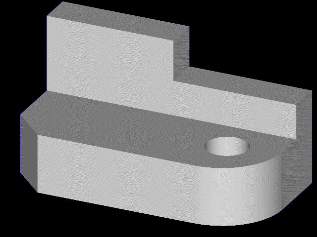
18 Complete the 3 view drawing (without dimensions for now). Begin by projecting all of the known information between the views.
19 Begin by projecting all of the known information between the views.
20 Heavy-up all of the object lines that depict visible object lines, and show surfaces that would not be visible in the specific orientation, using dashed/hidden lines.
21 Complete the right side view by projecting all of the relevant lines and points using a 45 degree miter line. Clean up the drawing.


22 Remove the final construction lines to see the finished drawing

23


24


25
26 2. Coordinate Dimensioning and Tolerancing ANSI standard - ASME Y14.5M The collective process of modeling, defining and describing geometric sizes and feature relationships, and providing all of the required technical information necessary to produce and inspect the part is called dimensioning and tolerancing. The National Standard for dimensioning and tolerancing in the United States is ASME Y14.5M DRAWN IN ACCORDANCE WITH ASME Y14.5M REMOVE ALL BURRS AND SHARP EDGES ALL FILLETS AND ROUNDS R.6 UNLESS OTHERWISE SPECIFIED Geometric Dimensioning and Tolerancing (GD&T) : ASME Y

27 Dimensioning Scheme deciding what, where, and how to add dimensions to the drawing 2
28 Object Lines Hidden Lines Center Lines Phantom Lines Dimension Lines Extension Lines Leader Lines Cutting Plane Line Sections - Hatching Break Lines Line Types thick thin thin thin thin thick thin thick
29 Arrowheads Arrowheads are used as terminators on dimension lines. The points of the arrowheads on leader lines and dimension lines must make contact with the feature object line or extension lines which represent the feature being dimensioned. The standard size ratio for all arrowheads on mechanical drawings is 3:1 (length to width). 2 R 8.5 Of the four different arrowhead types that are authorized by the national standard, ASME Y14.2M 1994, a filled arrowhead is the highest preference. 1st 2nd 3rd 4th
30 Dimension Lines and Extension Lines Extension lines overlap dimension lines (beyond the point of the arrowheads) by a distance of roughly 2-3mm There should be a visible gap (~1.5 mm) between the object lines and the beginning of each extension line Dimensions should be placed outside the actual part outline. Dimensions should not be placed within the part boundaries unless greater clarity would result.
31 Placement of Linear Dimensions Order of Preference Arrows in / dimension in 1.25 Arrows out / dimension in.75 Arrows in / dimension out.5 Arrows out / dimension out When there is not enough room between the extension lines to accommodate either the dimension value or the dimension lines they can be placed outside the extension lines as shown in the fourth example (use Flip Arrows in ProE).
32 Reference Dimensions Reference Dimension Symbol (X.XXX) EXAMPLE (.75) (.75) Reference dimensions are used on drawings to provide support information only. They are values that have been derived from other dimensions and therefore should not be used for calculation, production or inspection of parts. The use of reference dimensions on drawings should be minimized.
33 Location of Dimensions Shorter (intermediate) dimensions are placed closest to the outline of the part, followed by dimensions of greater length. Dimensions nearest the object outline should be at least.375 inches (1 mm) away from the object, and succeeding parallel dimension lines should be at least.25 inches (6 mm) apart (6mm) Minimum Spacing (1mm) Minimum Spacing Dimensions should be placed outside the actual part outline

34 Basic Dimensioning Good Practice Extension lines should not cross dimension lines if avoidable In-line dimensions can share arrowheads with contiguous dimensions BETTER
35 Diameter Dimensions Holes and cutouts THRU x.62 DP
36 Diameter Dimensions Shafts and Holes Whenever it is practical to do so, external diameters are dimensioned in rectangular (or longitudinal) views. Cylindrical holes, slotted holes, and cutouts that are irregular in shape would normally be dimensioned in views where their true geometric shape is shown..25 THRU
37 Placement with Polar Coordinates To dimension features on a round or axisymmetric component 3X.562 6X º 18º º 18º 18º 18º
38 Radial Dimensions To indicate the size of fillets, rounds, and radii R.312 R14.25 R.75 R.312 R.562
39 Angular Dimensions: To indicate the size of angular details appearing as either angular or linear dimensions. 92 º Length of Chord x 2 or 2 x 45 º 2 x 45Þ or 2 x 2 CHAM 5 or 13 Length of Arc or 63º 63Þ Alternate Chamfers 95
40 Times and By Symbol: X 8X.25 THRU.12 X 45º CHAMFER.375 CSK.562 X 82º The X symbol can also be used to indicate the word by. For instance, when a slot that has a given width by a specified length, or a chamfer that has equal sides (.12 X.12). When used to imply the word by, a space must precede and follow the X symbol. If the same feature is repeated on the drawing (such as 8 holes of the same diameter and in a specified pattern), the number of times the instruction applies is called out using the symbol X.
41 Section Views A SECTION A - A A Section views are used to clarify internal detail and to avoid dimensioning to hidden lines The are established by referencing a cutting plane Cutting planes depict the exact location on the part from which the section view will be projected, and should have associated arrowheads, indicating the direction from which the section view will be observed. Cutting planes are constructed as an integral feature of the parent view, and cutting plane arrowheads always indicate the direction for the observer s line of sight.
42 Cutting Plane Alpha Characters A - A, B - B, C C*, etc., are used to designate the required section view. The characters are placed near the arrowheads and as a subtitle of the view. There is no standard for the location of the section designators, other than near the cutting plane arrowheads as the examples below illustrate. When the alphabet has been exhausted, use double characters AA - AA, BB - BB, CC CC*, etc. *Section Designators should NOT include the alpha characters I, O, or Q. A Cutting plane on reference view A Subtitle of actual view SECTION A - A
43 Crosshatching Section Views Crosshatching, is a repeating graphic pattern which is applied throughout all areas of the part that would be in contact with the cutting plane. Thus, the hole is not crosshatched. The recommended angle for the standard crosshatch pattern is 45, 3, or 6 degrees with horizontal. Similarly, crosshatch lines should be neither parallel nor perpendicular to the outline of the feature in section if avoidable (see the examples below). Good Practice Poor Practice Poor Practice
44 Cross Hatch Standards The general purpose cross hatch is used in most individual detail component drawings and in assembly applications where no confusion will result. Each of the assembled components are depicted with a different crosshatch angle to assist in part differentiation. Specific crosshatch symbols are sometimes used to represent each different material type.
45 Cross Hatch Symbols Cast Iron (General Use) White Metal (Zinc) Sand Steel Magnesium, Aluminum Titanium Felt, Leather, & Fiber Bronze, Brass, etc. Concrete Marble, Slate, Glass, etc. Water, Liquids Wood; Cross Grain With Grain
46 Half Sections Half section views are the result of cutting planes being positioned on parts in such a manner that only half of the resulting view or projection is shown in section. Half sections are generally used on objects of symmetry, individual cylindrical parts, or assemblies of parts.
47 Half Sections Shown without section: Difficult to dimension without using hidden lines Internal features not as clear
48 D Offset Sections Offset sections allow us to provide greater breadth of detail with fewer section views. All of the features are aligned with the cutting plane. D SECTION D - D


49 Projected Section Views A A SECTION A A ROTATED 3º CLOCKWISE
50 Drawing Notes Notes should be concise and specific. They should use appropriate technical language, and be complete and accurate in every detail. They should be authored in such a way as to have only one possible interpretation. General Notes DRAWN IN ACCORDANCE WITH ASME Y14.5M REMOVE ALL BURRS AND SHARP EDGES ALL FILLETS AND ROUNDS R.6 UNLESS OTHERWISE SPECIFIED Local Notes 4X 8.2 M1 X º CSK X 45º CHAM
51 ASME/ANSI Hole Depth Symbol Depth or Deep Symbol* Features such as blind holes and counterbores, must have a depth called out to fully describe their geometry. EXAMPLE OR.375 * This symbol is currently not used in the ISO standard. It has been proposed.
52 ASME/ANSI Countersink Symbol Countersink Symbol* EXAMPLE The symbol denotes a requirement for countersunk holes used to recess flathead screws. The height of the symbol is equal to the letter height on the drawing, and the included angle is drawn at 9º. Note that this symbol is not used in the ISO (international) standard X 9º * This symbol is currently not used in the ISO standard. It has been proposed.
53 ASME/ANSI Counterbore Symbol Counterbore Symbol* This symbol denotes counterbored holes used to recess machine screw heads. EXAMPLE OR * This symbol is currently not used in the ISO standard. It has been proposed.
54 Screw Threads ISO specify metric only: ISO metric designation M 16 x 2 M 16 x 2-4h - 5H Nominal Diameter (mm) Thread Pitch(mm) Class of fit of this thread (optional) Class of fit of mating thread (optional) American Unified Threads: 3/4-1 - UNC Nominal Diameter (inches) 3/4-1 - UNC - 2A Threads per inch Thread Series UNC = Unified Coarse UNF = Unified Fine Thread Type (optional) A=External B=Internal Class of fit (optional) Note: Use standard screw sizes only
55 Fasteners etc Many CAD models available on-line from standard catalogs Good idea to use to ensure that you are using a readily available fastener Click to go to McMaster-Carr online site
56 Threads and Screw Fastening Always a 'Clearance Hole' (typically screw major Dia. + 1%) in at least one component in a screw fastened joint. Example Assembly 'A' Base 'A' 3 - M12 Hex. Screws Lid Section 'A'-'A'
57 Threads and Screw Fastening (cont.) Base Detail 'A' 3 Holes 1.3 x 25 DP M12x1.75 x 15 DP MIN EQ SP on 12 PD 'A' Section 'A'-'A'
58 Threads and Screw Fastening (cont.) Lid Detail 'A' 3 Holes 12.7 THRU EQ SP on 12 PD 'A' Section 'A'-'A'

59 Standard Tap and Clearance Drill Sizes - Metric
60 Tolerances important to interchangeability and provision for replacement parts It is impossible to make parts to an exact size. The tolerance, or accuracy required, will depend on the function of the part and the particular feature being dimensioned. Therefore, the range of permissible size, or tolerance, must be specified for all dimensions on a drawing, by the designer/draftsperson. Nominal Size: is the size used for general identification, not the exact size. Actual Size: is the measured dimension. A shaft of nominal diameter 1 mm may be measured to be an actual size of mm. General Tolerances: In ISO metric, general tolerances are specified in a note, usually in the title block, typically of the form: "General tolerances ±.25 unless otherwise stated". In English Units, the decimal place indicates the general tolerance given in the title block notes, typically: Fractions = ±1/16,.X = ±.3,.XX = ±.1,.XXX = ±.5,.XXXX = ±.5, Note: Fractions and this type of general tolerancing is not permissible in ISO metric standards.
61 Specific Tolerances Specific Tolerances indicate a special situation that cannot be covered by the general tolerance. Specific tolerances are placed on the drawing with the dimension and have traditionally been expressed in a number of ways: Bilateral Tolerance Unilateral Tolerance Limit Dimensions Limits are the maximum and minimum sizes permitted by the the tolerance. All of the above methods show that the dimension has: a Lower Limit = mm an Upper Limit = 4.5 mm a Tolerance =.8 mm Manufacturing must ensure that the dimensions are kept within the limits specified. Design must not over specify as tolerances have an exponential affect on cost.
62 Limits and Fits 1. Clearance Fits The largest permitted shaft diameter is smaller than the diameter of the smallest hole Max. Clearance Max. Hole Min. Hole Max. Shaft Min. Shaft Min. Clearance HOLE SHAFT
63 2. Interference Fits The minimum permitted diameter of the shaft is larger than the maximum diameter of the hole Max. Hole Min. Hole Max. Shaft Min. Shaft Max. Interference Min. Interference 3. Transition Fits The diameter of the largest allowable hole is greater than that of the smallest shaft, but the smallest hole is smaller than the largest shaft Max. Hole Min. Hole HOLE Interference or clearance Max. Shaft SHAFT Min. Shaft HOLE SHAFT
64 Limits of Clearance Limits of Clearance Limits of Clearance Limits of Clearance Limits of Clearance Limits of Clearance Standard Limits and Fits -- ANSI RC 1 Close sliding fits are intended for the accurate location of parts which must assemble without perceptible play. RC 2 Sliding fits are intended for accurate location, but with greater maximum clearance than class RC 1. Parts made to this fit move and turn easily but are not intended to run freely, and in the larger sizes may seize with small temperature changes. RC 3 Precision running fits are about the closest fits which can be expected to run freely, and are intended for precision work at slow speeds and light journal pressures, but are not suitable where appreciable temperature differences are likely to be encountered. RC 4 Close running fits are intended chiefly for running fits on accurate machinery with moderate surface speeds and journal pressures, where accurate location and minimum play are desired. RC 5 Medium running fits are intended for higher running speeds, or heavy journal pressures, or both. RC 6 Basic hole system. Limits are in thousandths of an inch. Nominal Size Range in Inches Class RC 1 Standard Limits Hole H5 Shaft g4 Class RC 2 Standard Limits Hole H6 Shaft g5 Class RC 3 Standard Limits Hole H7 Shaft f6 Class RC 4 Standard Limits Hole H8 Shaft f7 Class RC 5 Standard Limits Hole H8 Shaft e7 Class RC 6 Standard Limits Extract from Table of Clearance Fits Hole H9 Shaft e8
65 ISO Tolerance Designation The ISO system provides for: 21 types of holes (standard tolerances) designated by uppercase letters A, B, C, D, E...etc. and 21 types of shafts designated by the lower case letters a, b, c, d, e...etc. These letters define the position of the tolerance zone relative to the nominal size. To each of these types of hole or shaft are applied 16 grades of tolerance, designated by numbers IT1 to IT16 - the "Fundamental Tolerances": ITn = (.45 x 3 D +.1 D) Pn where D is the mean of the range of diameters and Pn is the progression:1, 1.6, 2.5, 4., 6., 1, 16, 25...etc. which makes each tolerance grade approximately 6% of its predecessor.
66 For Example: Experience has shown that the dimensional accuracy of manufactured parts is approximately proportional to the cube root of the size of the part. Example: A hole is specified as: 3 H7 The H class of holes has limits of +. i.e. all tolerances start at the nominal size and go positive by the amount designated by the IT number. + x IT7 for diameters ranging 3-5 mm: Tolerance for IT7 = (.45 x x 4) 16 =.25 mm Written on a drawing as 3 H

67 Graphical illustration of ISO standard fits Hole Series H hole Standard
68 Selection of Fits and the ISO Hole Basis system From the above it will be realized that there are a very large number of combinations of hole deviation and tolerance with shaft deviation and tolerance. However, a given manufacturing organization will require a number of different types of fit ranging from tight drive fits to light running fits for bearings etc. Such a series of fits may be obtained using one of two standard systems: The Shaft Basis System: For a given nominal size a series of fits is arranged for a given nominal size using a standard shaft and varying the limits on the hole. The Hole Basis System: For a given nominal size, the limits on the hole are kept constant, and a series of fits are obtained by only varying the limits on the shaft. The HOLE SYSTEM is commonly used because holes are more difficult to produce to a given size and are more difficult to inspect. The H series (lower limit at nominal,.) is typically used and standard tooling (e.g. H7 reamers) and gauges are common for this standard.
69 ISO Standard "Hole Basis" Clearance Fits Type of Fit Hole Shaft Loose Running Fits. Suitable for loose pulleys and the looser fastener fits where freedom of assembly is of prime importance Free Running Fit. Where accuracy is not essential, but good for large temperature variation, high running speeds, heavy journal pressures Close Running Fit. Suitable for lubricated bearing, greater accuracy, accurate location, where no substantial temperature difference is encountered. Sliding Fits. Suitable for precision location fits. Shafts are expensive to manufacture since the clearances are small and they are not recommended for running fits except in precision equipment where the shaft loadings are very light. Locational Clearance Fits. Provides snug fit for locating stationary parts; but can be freely assembled and disassembled. H11 H9 H8 H7 H7 c11 d1 f7 g6 h6
70 ISO Standard "Hole Basis Transition Fits Type of Fit Locational Transition Fits. for accurate location, a compromise between clearance and interference Push Fits. Transition fits averaging little or no clearance and are recommended for location fits where a slight interferance can be tolerated for the purpose, for example, of eliminating vibration. ISO Standard "Hole Basis" Interference Fits Type of Fit Press Fit. Suitable as the standard press fit into ferrous, i.e. steel, cast iron etc., assemblies. Drive Fit Suitable as press fits in material of low modulus of elasticity such as light alloys. Hole H7 H7 Hole H7 H7 Shaft k6 n6 Shaft p6 s6
71 ISO Clearance Fits Nominal Sizes Tolerance Tolerance Tolerance Tolerance Tolerance Tolerance Over To H11 c11 H9 d1 H9 e9 H8 f7 H7 g6 H7 h6 mm mm.1 mm.1 mm.1 mm.1 mm.1 mm.1 mm.1 mm.1 mm.1 mm.1 mm.1 mm.1 mm
72 Nominal Sizes Tolerance Over To H7 k6 H7 n6 mm mm.1 mm.1 mm.1 mm.1 mm ISO Transition Fits
73 Nominal Sizes Tolerance Tolerance Over To H7 p6 H7 s6 mm mm.1 mm.1 mm.1 mm.1 mm ISO Interference Fits

74 Flanged Sintered Bronze Plain Bearing
75

76

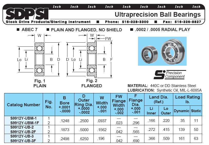
77 On-line Interactive Catalogs

78 Ball Bearing Design Considerations Allow float for thermal expansion and reduced axial tolerance requirements Click on pic to select SKF catalog page

79 Roller Bearing Design Considerations Roller Bearing provides float for thermal expansion and reduced axial tolerance requirements


80 Taper Roller Bearings for high axial and radial loads Preload to remove all axial clearance/play in the bearing
81 Tolerance Calculation - 'Worst Case Method' for correct fit in all cases, if manufactured to specification Allowance The minimum allowable difference between mating parts: Allowance = Smallest Hole Size - Largest Shaft Size Clearance The maximum allowable difference between mating parts: Clearance = Largest Hole Size - Smallest Shaft Size The 'Tolerance Build-up Problem' Where the combined dimension of several mating parts results in an unacceptable condition: generally non-functional (e.g. rotating or sliding action impaired), or parts will not assemble, or aesthetically unacceptable (e.g. inconsistent gaps around car doors) Hole 'Shaft in hole' Terminology Shaft
 Smallest Shaft Size (B) A If dimension with tolerance is 1 +.125 -.125 Lid on Box Example Largest feature size = 1.")
82 Shaft in Hole Example Worst Case Tolerancing A B 1. Allowance = Smallest Hole Size (A) Largest Shaft Size (B) 2. Clearance = Largest Hole Size (A) Smallest Shaft Size (B) A If dimension with tolerance is Lid on Box Example Largest feature size = Smallest feature size = The Tolerance is.25 i.e. the normalized overall range B
83 Tolerance Calculation - Tensioner Assy. Example A B Axial Clearance by by Design design must must be be <.25 => Š.25.1 but =< >.1.25 Worst Case Tolerancing: X 1. Allowance = Smallest Hole Size (76.16) Largest Shaft Size (76.15) =.1 2. Clearance = Largest Hole Size (76.25) Smallest Shaft Size (76.) =.25
84 Tolerance Calculation - Tensioner Assy. Example Hole +.16A B Axial Clearance by by Design design must must be be <.25 => Š.25.1 but =< >.1.25 X Shaft = Sum of 3 individual dimensions Worst Case Tolerancing: 1. Allowance = Smallest Hole Size (76.16) Largest Shaft Size (76.15) =.1 2. Clearance = Largest Hole Size (76.25) Smallest Shaft Size (76.) =.25

85
86 Lecture Class Assignment #11 Axial Tolerances, Fits and Limits Note: This is the type of analysis I want you to do for your design projects (See Design Project Appendix 3. Tolerance Analysis) Name: Section: Axial Fit (gap) Axial Fit - Tolerance Analysis Allowance: the minimum allowable difference between mating parts Clearance: the maximum allowable difference between mating parts Allowance = Smallest Hole Largest Shaft Clearance = Largest Hole Smallest Shaft A B Shaft C Allowance: Smallest Hole = Largest Shaft = = = A Clearance: Largest Hole = Smallest Shaft = = = B C Hole A B C 1. What is the axial allowance between the wheel subassembly and the shaft 2. What is the axial clearance between the wheel subassembly and the shaft
87 Surface Properties - Texture and Hardness Surface Finish Basic Surface Texture Symbol.4 With Roughness Value (Typically R a µm or µ ) Material Removal by Machining 2 With Machining Allowance Hardness Harden = HDN - may see symbol Heat Treat = H/T Rockwell = HRC, HRA etc or R a or R c Brinell = BNL.4 HDN to 65 HRC.125 DP
88 Comparative Roughness Values Roughness Ra Typical Processes 25 µm (1 µ ) Flame Cutting 12.5 µm (5µ ) Sawing, sand casting, 6.3 µm (25µ ) forging, shaping, planing 3.2 µm (125µ ) Rough machining, milling, rough turning, drilling, and die casting 1.6 µm (63µ ) Machining, turning, milling, die and investment casting, injection molding, and stamping.8 µm (32µ ) Grinding, fine turning & milling, reaming, honing, injection molding, stamping, investment casting.4 µm (16µ ) Diamond Turning, Grinding, lapping, honing.2 µm (8µ ) Lapping, honing, polishing.1 µm (4µ ) Superfinishing, polishing, lapping
89 Some Common Steel, Hardness and Surface Finish Specs. Common Steel Specs: (1xx series: xx = % carbon) Mild steel (low carbon = up to 3 %): Low cost general purpose applications, typ. hardening not required Medium Carbon (up to 6%): requiring higher strength; e.g. gears, axles, conrods etc. 14, 16 High Carbon (> 6%): High wear, high strength; e.g. cutting tools, springs etc. 18 Ground Bearing Shaft Examples: General Purpose 16: Surface HDN to 55 HRC.125 mm deep min.;.4 µm (16 µ ) 33 Stainless: (natural surface hardness 5 HRC );.4µm (16 µ ) Better Finish, Longer Life 12: Case HDN to 65 HRC.25 mm deep min.;.2µm (8 µ ) 44 Stainless: (natural circa 15 HRC);.2µm (8 µ ) Common Types 12
90 Specifying Welds on Drawings Weld all Around Weld on other side Pitch Length Weld on arrow side Width of weld = Weld 6mm fillet weld this side only = 6 = Weld 6mm fillet weld both sides 3 =
ENGINEERING GRAPHICS ESSENTIALS. (A Text and Lecture Aid) Second Edition. Kirstie Plantenberg University of Detroit Mercy SDC PUBLICATIONS
 Second Edition. Kirstie Plantenberg University of Detroit Mercy SDC PUBLICATIONS") ENGINEERING GRAPHICS ESSENTIALS (A Text and Lecture Aid) Second Edition Kirstie Plantenberg University of Detroit Mercy SDC PUBLICATIONS Schroff Development Corporation www.schroff.com www.schroff-europe.com
ENGINEERING GRAPHICS ESSENTIALS (A Text and Lecture Aid) Second Edition Kirstie Plantenberg University of Detroit Mercy SDC PUBLICATIONS Schroff Development Corporation www.schroff.com www.schroff-europe.com
the same information given in two different 1. Dimensions should NOT be duplicated, or Dimension Guidelines Incorrect ways.
 Dimension Guidelines 1. Dimensions should NOT be duplicated, or the same information given in two different ways. Incorrect 1. Dimensions should NOT be duplicated, or the same information given in two
Chapter 2: Dimensioning Basic Topics Advanced Topics Exercises
 Chapter 2: Dimensioning Basic Topics Advanced Topics Exercises Dimensioning: Basic Topics Summary 2-1) Detailed Drawings 2-2) Learning to Dimension 2-3) Dimension Appearance and Techniques. 2-4) Dimensioning
Dimensioning. Dimensions: Are required on detail drawings. Provide the shape, size and location description: ASME Dimensioning Standards
 Dimensioning Dimensions: Are required on detail drawings. Provide the shape, size and location description: - Size dimensions - Location dimensions - Notes Local notes (specific notes) General notes ASME
A Brief Introduction to Engineering Graphics. Will Durfee & Tim Kowalewski Department of Mechanical Engineering University of Minnesota
 A Brief Introduction to Engineering Graphics Will Durfee & Tim Kowalewski Department of Mechanical Engineering University of Minnesota Opening comments Engineering graphics is the method for documenting
Drawing & Design. Lecture 3. Lecturer: Dr. John Cheung
 MECH 313 Engineering Drawing & Design Lecture 3 Lecturer: Dr. John Cheung Outline Limits and tolerances Fits and allowances Surface texture Why ygive Tolerance? Manufacturing Practice is 6000 years old,
Engineering drawing. Semester I/II Mechanical Engineering Department Technical University of Gdańsk. Lecture 8
 Engineering drawing Semester I/II Mechanical Engineering Department Technical University of Gdańsk Lecture 8 Representing Tolerance Values Tolerance is the total amount a dimension may vary and is the
DFTG-1305 Technical Drafting Prof. Francis Ha
 DFTG-1305 Technical Drafting Prof. Francis Ha Session 5 Dimensioning Geisecke s textbook: 14 th Ed. Chapter 10 p. 362 15 th Ed. Chapter 11 p. 502 Update: 17-0508 Dimensioning Part 1 of 2 Dimensioning Summary
Geometric dimensioning & tolerancing (Part 1) KCEC 1101
 KCEC 1101") Geometric dimensioning & tolerancing (Part 1) KCEC 1101 Introduction Before an object can be built, complete information about both the size and shape of the object must be available. The exact shape of
Geometric dimensioning & tolerancing (Part 1) KCEC 1101 Introduction Before an object can be built, complete information about both the size and shape of the object must be available. The exact shape of
TECHNICAL DESIGN II (546)
") DESCRIPTION The second in a sequence of courses that prepares individuals with an emphasis in developing technical knowledge and skills to develop working drawings in support of mechanical and industrial
DESCRIPTION The second in a sequence of courses that prepares individuals with an emphasis in developing technical knowledge and skills to develop working drawings in support of mechanical and industrial
Engineering Design Representation. Use of 2D drawing format: Typical Design Annotation. Standardization. Extracted drawings. General dimensions
 Engineering Design Representation Some elements of design representation not easily conveyed through model alone. Many are notational in nature. Examples are: Thread specifications Surface finishes Surface
Elementary Dimensioning
 Elementary Dimensioning Standards Institutions ANSI - American National Standards Institute - creates the engineering standards for North America. ISO - International Organization for Standardization -
ME 114 Engineering Drawing II
 ME 114 Engineering Drawing II FITS, TOLERANCES and SURFACE QUALITY MARKS Mechanical Engineering University of Gaziantep Dr. A. Tolga Bozdana Assistant Professor Tolerancing Tolerances are used to control
Geometric Dimensioning and Tolerancing
 Geometric Dimensioning and Tolerancing (Known as GDT) What is GDT Helps ensure interchangeability of parts. Use is dictated by function and relationship of the part feature. It does not take the place
Geometric Boundaries II
 Geometric Boundaries II Interpretation and Application of Geometric Dimensioning and Tolerancing (Using the Inch and Metric Units) Based on ASME Y14.5-2009 (R2004) Written and Illustrated by Kelly L. Bramble
Assembly of Machine Parts
 Machine Drawing Assembly of Machine Parts Temporary Permanent Fastening Keying Fitting Welding Riveting Interference fit Machine drawing is the indispensable communicating medium employed in industries,
1 st Subject: Types and Conventions of Dimensions and Notes
 Beginning Engineering Graphics 7 th Week Lecture Notes Instructor: Edward N. Locke Topic: Dimensions, Tolerances, Graphs and Charts 1 st Subject: Types and Conventions of Dimensions and Notes A. Definitions
Chapter Tests and Problems
 Chapter Tests and Problems Chapter 11 Fasteners and Springs Test INSTRUCTIONS Answer the questions with short, complete statements or drawings as needed. QUESTIONS Define the screw thread terms given in
Engineering Working Drawings Basics
 Engineering Working Drawings Basics Engineering graphics is an effective way of communicating technical ideas and it is an essential tool in engineering design where most of the design process is graphically
ENGINEERING GRAPHICS ESSENTIALS
 ENGINEERING GRAPHICS ESSENTIALS with AutoCAD 2012 Instruction Introduction to AutoCAD Engineering Graphics Principles Hand Sketching Text and Independent Learning CD Independent Learning CD: A Comprehensive
Mechanical Drawing. Unit 2 Study Guide for Chapters 6-10
 Mechanical Drawing Unit 2 Study Guide for Chapters 6-10 Chapter 6 Multiview Drawing Section 6.1 Understanding Orthographic Projection A. Technical Drawing: How can a technical drawing give more accurate
Geometric Boundaries
 Geometric Boundaries Interpretation and Application of Geometric Dimensioning and Tolerancing (Using the Customary Inch System) Based on ASME Y14.5M-1994 Written and Illustrated by Kelly L. Bramble Published
METRIC FASTENERS 1520 METRIC FASTENERS
 1520 METRIC FASTENERS METRIC FASTENERS A number of American National Standards covering metric bolts, screws, nuts, and washers have been established in cooperation with the Department of Defense in such
1/2/2016. Lecture Slides. Screws, Fasteners, and the Design of Nonpermanent Joints. Reasons for Non-permanent Fasteners
 Lecture Slides Screws, Fasteners, and the Design of Nonpermanent Joints Reasons for Non-permanent Fasteners Field assembly Disassembly Maintenance Adjustment 1 Introduction There are two distinct uses
Advanced Dimensional Management LLC
 Index: Mechanical Tolerance Stackup and Analysis Bryan R. Fischer Accuracy and precision 8-9 Advanced Dimensional Management 14, 21, 78, 118, 208, 251, 286, 329-366 Ambiguity 4, 8-14 ASME B89 48 ASME Y14.5M-1994
SYSTEM OF LIMITS, FITS, TOLERANCES AND GAUGING
 UNIT 2 SYSTEM OF LIMITS, FITS, TOLERANCES AND GAUGING Introduction Definition of limits Need for limit system Tolerance Tolerance dimensions ( system of writing tolerance) Relationship between Tolerance
: Fits and Tolerances
 Fits and Tolerances CONTENTS Why tolerances and fits are required? Due to the inevitable inaccuracy of manufacturing methods, a part cannot be made precisely to a given dimension, the difference between
9000 Level. DS-703 Page 1 of 22 3 TITLE WORK INSTRUCTIONS, GENERAL PRINT AMENDMENT
 evel DS-70 Page 1 of 22 TITE WORK INSTRUCTIONS, GENERA PRINT AMENDMENT Revision EXPANATION OF CHANGE Approvals DATE A Initial Release WB, GR 2/26/99 B C D E F G Add PMR caveat WB, GR 5/1/99 Add Surface
Representation of features Geometric tolerances. Prof Ahmed Kovacevic
 ME 1110 Engineering Practice 1 Engineering Drawing and Design - Lecture 6 Representation of features Geometric tolerances Prof Ahmed Kovacevic School of Engineering and Mathematical Sciences Room C130,
Understanding Drawings
 Chapter 3 Understanding Drawings LEARNING OBJECTIVES After studying this chapter, students will be able to: Read drawings that are dimensioned in fractional inches, decimal inches, and in metric units.
Precision Manufacturing
 Precision Manufacturing 216 North Main Street. Freeport, NY 11520 Phone: 888-260-7466 / Fax: 516-771-6444 sales@ondrivesus.com www.ondrivesus.com Know Linear Your Shaft Shoulder Supports Screws By Dennis
Dimensioning 2-4) Dimensioning and Locating Simple Features
 Dimensioning and Locating Simple Features") Dimensioning 2-4) Dimensioning and Locating Simple Features Dimensioning Features a) A circle is dimensioned by its diameter and an arc by its radius using a leader line and a note. Exercise 2-6 Circular
Dimensioning 2-4) Dimensioning and Locating Simple Features Dimensioning Features a) A circle is dimensioned by its diameter and an arc by its radius using a leader line and a note. Exercise 2-6 Circular
Fits and Tolerances. Prof Ahmed Kovacevic
 ME 1110 Engineering Practice 1 Engineering Drawing and Design - Lecture 7 Fits and Tolerances Prof Ahmed Kovacevic School of Engineering and Mathematical Sciences Room C130, Phone: 8780, E-Mail: a.kovacevic@city.ac.uk
Engineering Graphics, Class 8 Orthographic Projection. Mohammad I. Kilani. Mechanical Engineering Department University of Jordan
 Engineering Graphics, Class 8 Orthographic Projection Mohammad I. Kilani Mechanical Engineering Department University of Jordan Multi view drawings Multi view drawings provide accurate shape descriptions
Continuous thick. Continuous thin. Continuous thin straight with zigzags. Dashed thin line. Chain thin. Chain thin double dash
 Types of line used Continuous thick Used for visible outlines and edges. Continuous thin Used for projection, dimensioning, leader lines, hatching and short centre lines. Continuous thin straight with
2001 Academic Challenge
 Worldwide Youth in Science and Engineering 2001 Academic Challenge ENGINEERING GRAPHICS TEST - STATE FINALS GENERAL DIRECTIONS Engineering Graphics Test Production Team Ralph Dirksen, Western Illinois
DIMENSIONING ENGINEERING DRAWINGS
 DIMENSIONING ENGINEERING DRAWINGS An engineering drawing must be properly dimensioned in order to convey the designer s intent to the end user. Dimensions provide the information needed to specify the
UNIT Lines and Symbols
 3 UNIT Lines and Symbols Various lines on a drawing have different meanings. They may appear solid, broken, thick, or thin. Each is designed to help the blueprint reader make an interpretation. The standards
Tool and Die Maker Level 2
 Level 2 B2 Read and Interpret Drawings II Duration: 32 hours 32 hours 0 hours This unit of instruction introduces the Tool and Die Maker Apprentice with the knowledge and skills necessary to read and interpret
Contents. Notes on the use of this publication
 Contents Preface xxiii Scope Notes on the use of this publication xxv xxvi 1 Layout of drawings 1 1.1 General 1 1.2 Drawing sheets 1 1.3 Title block 2 1.4 Borders and frames 2 1.5 Drawing formats 2 1.6
Reamer Basics. Fixed Reamers The reamer size is fixed and any size reduction due to wear or sharpening cannot be reclaimed
 1 Reamer Basics Reamers are available in a variety of types, materials, flute styles and sizes The typical reamer is a rotary cutting tools designed to machine a previously formed hole to an exact diameter
Metals can be bought from suppliers in standardized forms and sizes, such as round,
 1.4 METAL CUTTING BAND SAWS: Metals can be bought from suppliers in standardized forms and sizes, such as round, rectangular or square bar stock or in the form of large sheets (plates). Bar stock normally
UNIT 9b: SCREW FASTENERS Introduction Functions Screw Features Elements Terms of a Thread Profile
 UNIT 9b: SCREW FASTENERS Introduction A mechanical screw is a cylinder or cone that has a helical ridge called a thread. A helix has one or more turns, so a screw can have several turns. If the helix is
Fastener Handout. Introduction: Engineering Design Representation 2. Threads 2. Local Notes (callouts) 8. Threaded Mechanical Fasteners 13
 8. Threaded Mechanical Fasteners 13") Fastener Handout Introduction: Engineering Design Representation 2 Threads 2 Effect of thread angle on strength: 3 Standardization of Threads: 4 Descriptions of the Thread Series: 4 Class fit: 5 Specification
Fastener Handout Introduction: Engineering Design Representation 2 Threads 2 Effect of thread angle on strength: 3 Standardization of Threads: 4 Descriptions of the Thread Series: 4 Class fit: 5 Specification
Unit4 31. UnitS 39. Unit 6 47
 Preface..................... xi About the Author......... xiii Acknowledgments... xiv Unit 1 1 Bases for Interpreting Drawings........ I Visible Lines............. 3 Lettering on Drawings... 3 Sketching...
A Concise Introduction to Engineering Graphics
 A Concise Introduction to Engineering Graphics Fourth Edition Including Worksheet Series A Timothy J. Sexton, Professor Department of Industrial Technology Ohio University BONUS Book on CD: TECHNICAL GRAPHICS
ROOP LAL Unit-6 Lathe (Turning) Mechanical Engineering Department
 Mechanical Engineering Department") Notes: Lathe (Turning) Basic Mechanical Engineering (Part B) 1 Introduction: In previous Lecture 2, we have seen that with the help of forging and casting processes, we can manufacture machine parts of
Notes: Lathe (Turning) Basic Mechanical Engineering (Part B) 1 Introduction: In previous Lecture 2, we have seen that with the help of forging and casting processes, we can manufacture machine parts of
Drawing and Detailing with SolidWorks 2014
 r n fo io n at io c at tifi ar er ep c pr WT es D R u d Pcl In C S W e th W E N Drawing and Detailing with SolidWorks 2014 Referencing the ASME Y14 Engineering Drawing and Related Documentation Practices
Glass Box Projection. Gives you 6 sides to view of an object. 10/2/14 2
 2D Drawings Glass Box Projection Gives you 6 sides to view of an object. 10/2/14 2 We can simplify this for some objects to 3 views Glass Box Approach Glass Box Approach Glass Box Approach Glass Box Approach
Multiviews and Auxiliary Views
 Multiviews and Auxiliary Views Multiviews and Auxiliary Views Objectives Explain orthographic and multiview projection. Identifying the six principal views. Apply standard line practices to multiviews
UNIT 5a STANDARD ORTHOGRAPHIC VIEW DRAWINGS
 UNIT 5a STANDARD ORTHOGRAPHIC VIEW DRAWINGS 5.1 Introduction Orthographic views are 2D images of a 3D object obtained by viewing it from different orthogonal directions. Six principal views are possible
Quality Procedure QP159 General Requirements for Machined Parts
 1. PURPOSE 1.1. This procedure provides general product fabrication requirements. It also provides interpretation of certain requirements specified on product drawings, models, and electronic files. 2.
Test Answers and Exam Booklet. Geometric Tolerancing
 Test Answers and Exam Booklet Geometric Tolerancing iii Contents ANSWERS TO THE GEOMETRIC TOLERANCING TEST............. 1 Part 1. Questions Part 2. Calculations SAMPLE ANSWERS TO THE GEOMETRIC TOLERANCING
COMMON SYMBOLS/ ISO SYMBOL ASME Y14.5M ISO FEATURE CONTROL FRAME DIAMETER/ SPHERICAL DIAMETER/ AT MAXIMUM MATERIAL CONDITION
 1 82 COMMON SYMBOLS/ Shown below are the most common symbols that are used with geometric tolerancing and other related dimensional requirements on engineering drawings. Note the comparison with the ISO
SOLIDWORKS 2015 and Engineering Graphics
 SOLIDWORKS 2015 and Engineering Graphics An Integrated Approach Randy H. Shih SDC PUBLICATIONS Better Textbooks. Lower Prices. www.sdcpublications.com Powered by TCPDF (www.tcpdf.org) Visit the following
Geometric Dimensioning and Tolerancing
 Geometric dimensioning and tolerancing (GDT) is Geometric Dimensioning and Tolerancing o a method of defining parts based on how they function, using standard ASME/ANSI symbols; o a system of specifying
Principles and Practice:
 Principles and Practice: An Integrated Approach to Engineering Graphics and AutoCAD 2014 Randy H. Shih Multimedia Disc SDC PUBLICATIONS Better Textbooks. Lower Prices. www.sdcpublications.com Video presentations
Guide To British Standards
 Guide To British Standards Higher Graphic Communication C O N T E N T S page TITLE BLOCK 2 DRAWING SCALES 2 LINE TYPES 3 ORTHOGRAPHIC PROJECTION 4 SECTIONAL VIEWS 4 SCREW THREADS & COMPONENTS 7 INTERUPTTED
Designing for machining round holes
 Designing for machining round holes Introduction There are various machining processes available for making of round holes. The common processes are: drilling, reaming and boring. Drilling is a machining
Session 10 Dimensions, Fits and Tolerances for Assembly
 Session 10 Dimensions, Fits and Tolerances for Assembly Lecture delivered by Prof. M. N. Sudhindra Kumar Professor MSRSAS-Bangalore 1 Variations in Production It is necessary that the dimensions, shape
Trade of Metal Fabrication. Module 3: Plate Fabrication Unit 12: Duct Sections Phase 2
 Trade of Metal Fabrication Module 3: Plate Fabrication Unit 12: Duct Sections Phase 2 Table of Contents List of Figures... 4 List of Tables... 5 Document Release History... 6 Module 3 Plate Fabrication...
Trade of Toolmaking. Module 5: Press Tools, Jigs & Fixtures, Mouldmaking Unit 2: Blanking Tool (Unguided) Phase 2. Published by
 Phase 2. Published by") Trade of Toolmaking Module 5: Press Tools, Jigs & Fixtures, Mouldmaking Unit 2: Blanking Tool (Unguided) Phase 2 Published by SOLAS 2014 Unit 2 1 Table of Contents Document Release History... 3 Unit Objective...
Trade of Toolmaking Module 5: Press Tools, Jigs & Fixtures, Mouldmaking Unit 2: Blanking Tool (Unguided) Phase 2 Published by SOLAS 2014 Unit 2 1 Table of Contents Document Release History... 3 Unit Objective...
FACULTY OF ENGINEERING DESIGN AND PRODUCTION ENGINEERING DEPARTMENT. Credit Hour System Metrology Lab 1 MDP 240 (1) Fixed gauges. Metrology laboratory
 Fixed gauges. Metrology laboratory") FACULTY OF ENGINEERING DESIGN AND PRODUCTION ENGINEERING DEPARTMENT Report On: Credit Hour System Metrology Lab 1 MDP 240 (1) Fixed gauges Metrology laboratory Class No: B.N. Student Name Remark Signature
FACULTY OF ENGINEERING DESIGN AND PRODUCTION ENGINEERING DEPARTMENT Report On: Credit Hour System Metrology Lab 1 MDP 240 (1) Fixed gauges Metrology laboratory Class No: B.N. Student Name Remark Signature
Taps. Taps - Technical Info. Torque Cut High Performance HSSE Ring Colored Taps Technical Information. - Technical Information
 Torque Cut High Performance HSSE Ring Colored Taps Technical Information RedLine Torque Cut High Performance Taps give you greater performance when tapping Steel Alloys, Stainless Steels, Titanium and
2004 Academic Challenge
 2004 Academic Challenge ENGINEERING GRAPHICS TEST - SECTIONAL Engineering Graphics Test Production Team Ryan Brown, Illinois State University Author/Team Coordinator Kevin Devine, Illinois State University
C H A P T E R E L E V E N
 DIMENSIONING C H A P T E R E L E V E N Giesecke, Hill, Spencer, Dygdon, Novak, Lockhart, Goodman 1 OBJECTIVES 1. Use conventional dimensioning techniques to describe size and shape accurately on an engineering
Standards for Your Career Field
 Dimensioning Dimensions Dimensions are used to describe the sizes and relationships between features in your drawing. Dimensions are used to manufacture parts and to inspect the resulting parts to determine
Design Guide: CNC Machining VERSION 3.4
 Design Guide: CNC Machining VERSION 3.4 CNC GUIDE V3.4 Table of Contents Overview...3 Tolerances...4 General Tolerances...4 Part Tolerances...5 Size Limitations...6 Milling...6 Lathe...6 Material Selection...7
TECH SHEET PEM - REF / AXIAL THREAD CLEARANCE. SUBJECT: Method for providing adequate axial thread clearance
 SUBJECT: Method for providing adequate axial thread clearance In our long history of working with customers in the application of our self-clinching nuts, PennEngineering has seen numerous instances of
Principles and Practice
 Principles and Practice An Integrated Approach to Engineering Graphics and AutoCAD 2016 Randy H. Shih SDC PUBLICATIONS Better Textbooks. Lower Prices. www.sdcpublications.com Powered by TCPDF (www.tcpdf.org)
Tolerancing. Summary
 Tolerancing Summary Summary What will we learn We will learn about tolerancing and how important this technique is to mass production. Key points If a feature s size is toleranced, it is allowed to vary
GEOMETRIC DIMENSIONING AND TOLERANCING (GD&T)
") GEOMETRIC DIMENSIONING AND TOLERANCING (GD&T) Based on ASME Y14.5M-1994 Standard Duration : 4 days Time : 9:00am 5:00pm Methodology : Instructor led Presentation, exercises and discussion Target : Individuals
GEOMETRIC DIMENSIONING AND TOLERANCING (GD&T) Based on ASME Y14.5M-1994 Standard Duration : 4 days Time : 9:00am 5:00pm Methodology : Instructor led Presentation, exercises and discussion Target : Individuals
Metal Drilling
 www.irwin.com Metal Drilling Engineered for Controlled Precision and Speed Shank Diameter Shank Point Angle Drill Bit Diameter : The length from the point to the end of the drill bit Point Angle: The angle
Thread Mills. Solid Carbide Thread Milling Cutters
 Thread Mills Solid Carbide Thread Milling Cutters Thread milling cutters by Features and Benefits: Sub-micro grain carbide substrate Longer tool life with tighter tolerances More cost-effective than indexable
MATERIAL AND EQUIPMENT STANDARD FOR METRIC TYPE FASTENERS (SCREWS, BOLTS, STUDS, NUTS AND WASHERS) ORIGINAL EDITION DEC. 1997
 ORIGINAL EDITION DEC. 1997") MATERIAL AND EQUIPMENT STANDARD FOR METRIC TYPE FASTENERS (SCREWS, BOLTS, STUDS, NUTS AND WASHERS) ORIGINAL EDITION DEC. 1997 This Standard is the property of Iranian Ministry of Petroleum. All rights
MATERIAL AND EQUIPMENT STANDARD FOR METRIC TYPE FASTENERS (SCREWS, BOLTS, STUDS, NUTS AND WASHERS) ORIGINAL EDITION DEC. 1997 This Standard is the property of Iranian Ministry of Petroleum. All rights
2012 Academic Challenge
 2012 Academic Challenge ENGINEERING GRAPHICS TEST SECTIONAL This Test Consists of 40 Questions Engineering Graphics Test Production Team Ryan Brown, Illinois State University Author/Team Leader Jacob Borgerson,
NABTEB Past Questions and Answers - Uploaded online PAST QUESTIONS AND ANSWERS GENERAL METAL WORK MAY/JUNE 2009
 PAST QUESTIONS AND ANSWERS GENERAL METAL WORK MAY/JUNE 2009 1a. Enumerate TWO safety measures each as regards the use of the following hand tools. 1. Scriber 2. Chisel 3. File 4. Try-square 1. Scriber:
Question. Question. Product Features The Vocabulary of Design Download from web site. CAD/Fab Orthographic Projection 4
 Orthographic Projection Question What is the name of the feature indicated? A. Countersink B. Counterbore C. Spotface D. Hole E. Stepped hole CAD/Fab Assemblies & Mobility 2 Question Product Features The
Student Name: Teacher: Date: District: Rowan. Assessment: 9_12 T and I IC61 - Drafting I Test 2. Description: Drafting 1 - Test 6.
 Student Name: Teacher: Date: District: Rowan Assessment: 9_12 T and I IC61 - Drafting I Test 2 Description: Drafting 1 - Test 6 Form: 501 1. 2X on a hole note means: A. Double the size of the hole. B.
2009 Academic Challenge
 2009 Academic Challenge ENGINEERING GRAPHICS TEST SECTIONAL This Test Consists of 50 Questions Engineering Graphics Test Production Team Ryan Brown, Illinois State University Author/Team Leader Kevin Devine,
Laboratory Exercises
 Laboratory Exercises 4 : 1 Lab 1A Inverted T Inverted T. Draw the solid object shown. Place the origin at the intersection of the faces with the holes in them. The front face is marked for you. Make sure
and Engineering Graphics
 SOLIDWORKS 2018 and Engineering Graphics An Integrated Approach Randy H. Shih SDC PUBLICATIONS Better Textbooks. Lower Prices. www.sdcpublications.com Powered by TCPDF (www.tcpdf.org) Visit the following
DRAFTING MANUAL. Dimensioning and Tolerancing Rules
 Page 1 1.0 General This section is in accordance with ASME Y14.5-2009 Dimensioning and Tolerancing. Note that Rule #1 is the only rule that is numbered in the 2009 standard. All of the other rules fall
CHAPTER 01 PRESENTATION OF TECHNICAL DRAWING. Prepared by: Sio Sreymean
 CHAPTER 01 PRESENTATION OF TECHNICAL DRAWING Prepared by: Sio Sreymean 2015-2016 Why do we need to study this subject? Effectiveness of Graphics Language 1. Try to write a description of this object. 2.
Mechanical Systems & Tools Syllabus [Detailed]
![Mechanical Systems & Tools Syllabus [Detailed]](/thumbs/89/101179107.jpg "Mechanical Systems & Tools Syllabus [Detailed]") TECHNICAL TRAINING - SWAPPING DOWNTIME FOR PRODUCTIVITY! Mechanical Systems & Tools Syllabus [Detailed] Your automation.ie Fact Sheets! Understand Mechanical Energy Types! 1 Staying Safe in the Mechanical
TECHNICAL TRAINING - SWAPPING DOWNTIME FOR PRODUCTIVITY! Mechanical Systems & Tools Syllabus [Detailed] Your automation.ie Fact Sheets! Understand Mechanical Energy Types! 1 Staying Safe in the Mechanical
AutoCAD Tutor 2011 Support Docs
 AutoCAD Tutor 2011 Support Docs CHAPTER 1 CUSTOMIZING THE QUICK ACCESS TOOLBAR One of the advantages of the Quick Access Toolbar is the ability to display the AutoCAD commands that you frequently use.
LANDMARK UNIVERSITY, OMU-ARAN
 LANDMARK UNIVERSITY, OMU-ARAN LECTURE NOTE: DRILLING. COLLEGE: COLLEGE OF SCIENCE AND ENGINEERING DEPARTMENT: MECHANICAL ENGINEERING PROGRAMME: MECHANICAL ENGINEERING ENGR. ALIYU, S.J Course code: MCE
Module 1 Fundamentals of machine design. Version 2 ME, IIT Kharagpur
 Module 1 Fundamentals of machine design Lesson 3 Brief overview of design and manufacturing Instructional Objectives: At the end of this lesson, the students should be able to understand: Concept of limits
High Performance HSSE Color Ring Tap Speeds
 Torque Cut High Performance HSSE Color Ring Taps RedLine Torque Cut High Performance Taps give you greater performance when tapping Steel Alloys, Stainless Steels, Titanium and a variety of other Steels
3. The dimensioning SYMBOLS for arcs and circles should be given:
 Draft Student Name: Teacher: District: Date: Wake County Test: 9_12 T and I IC61 - Drafting I Test 2 Description: 4.08 Dimensioning Form: 501 1. The MINIMUM amount of space between two, ADJACENT DIMENSION
ENGINEERING GRAPHICS ESSENTIALS
 ENGINEERING GRAPHICS ESSENTIALS Text and Digital Learning KIRSTIE PLANTENBERG FIFTH EDITION SDC P U B L I C AT I O N S Better Textbooks. Lower Prices. www.sdcpublications.com ACCESS CODE UNIQUE CODE INSIDE
TAPTITE Fasteners. High Performance Thread Rolling Screws for Metals
 TAPTITE 2000 Fasteners High Performance Thread Rolling Screws for Metals TAPTITE 2000 thread forming technology joins two unique concepts and advances fastener performance to new levels. TAPTITE 2000 fasteners
BASIC TECHNICAL INFORMATION FOR REAMERS FLUTE STYLES
 BASIC TECHNICAL INFORMATION FOR HANNIBAL CARBIDE would like to inform you of some basic technical knowledge regarding reamers. Following these guidelines will reduce overall set-up time, while increasing
WHAT? WHERE? HOW?
 JIGS WHAT? WHERE? HOW? Introduction Mass production aims at high productivities to reduce unit cost and inter-changeabilites to facilitate easy assembly. Jigs are useful in mass production. They provide
Thread Repair & Thread Protection
 Thread Repair & Thread Protection Screw Thread Inserts, Kits & Components for Industrial Maintenance, Repair and Overhaul Bulletin 998 C E R T I F I E D ISO 9001 AS 9100 TS 16949 ISO 14001 The HELI-COIL
THREAD CUTTING & FORMING
 THREAD CUTTING & FORMING Threading, Thread Cutting and Thread Rolling: Machining Threads on External Diameters (shafts) Tapping: Machining Threads on Internal Diameters (holes) Size: Watch to 10 shafts
MACHINIST TECHNICIAN - LATHE (582)
") DESCRIPTION Students will demonstrate technical knowledge and skills to plan, manufacture, assemble, test products, and modify metal parts using machine shop and CNC processes in support of other manufacturing,
DESCRIPTION Students will demonstrate technical knowledge and skills to plan, manufacture, assemble, test products, and modify metal parts using machine shop and CNC processes in support of other manufacturing,
Machinist NOA (1998) Subtask to Unit Comparison
 Subtask to Unit Comparison") Machinist NOA (1998) Subtask to Unit Comparison NOA Subtask Task 1 Demonstrates safe working practices. 1.01 Recognizes potential health and safety hazards. A1 Safety in the Machine Shop 1.02 Recognizes
Machinist NOA (1998) Subtask to Unit Comparison NOA Subtask Task 1 Demonstrates safe working practices. 1.01 Recognizes potential health and safety hazards. A1 Safety in the Machine Shop 1.02 Recognizes
Manufacturing Technician Training
 Mike McKinney / Jefferson College I. Objective: Developed to meet the industry demands and provide a six-week certification program to fast track individuals to secure a position in the manufacturing industry
Type XTSR71 Sizes
 (Page 1 of 13) s 494-5258 Type XTSR71 s 494-5258 Figure 1 Thomas XTSR71 Coupling 1. General Information 1.1 Thomas Couplings are designed to provide a mechanical connection between the rotating shafts