Representation of features Geometric tolerances. Prof Ahmed Kovacevic
|
|
|
- William Shields
- 6 years ago
- Views:
Transcription

1 ME 1110 Engineering Practice 1 Engineering Drawing and Design - Lecture 6 Representation of features Geometric tolerances Prof Ahmed Kovacevic School of Engineering and Mathematical Sciences Room C130, Phone: 8780, a.kovacevic@city.ac.uk 1
2 Objectives for today How to represent standard engineering features Gears; Bearings; Seals; Springs Shafts, tubes; Fasteners What are tolerances and how are they specified Geometric tolerances Surface finish & machining 2


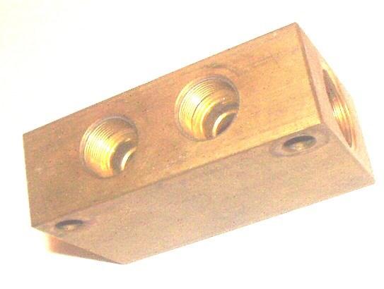
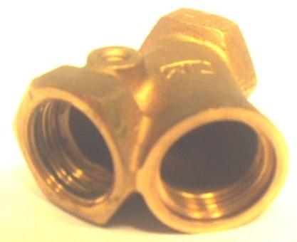

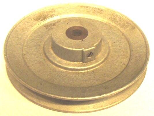
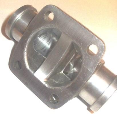
3 Exercise DrE-5 - Week 7 Parts to be measured and drawn 3
4 Representing standard features 4
5 Gears 5
6 Terminology and representation of standard components 6
7 Terminology and representation of standard components 7
8 Terminology and representation of standard components 8
9 Terminology and representation of standard components 9
10 Terminology and representation of standard components 10
11 Terminology and representation of standard components 11
12 Terminology and representation of standard components 12
13 Terminology and representation of standard components 13
14 Terminology and representation of standard components 14
15 Terminology and representation of standard components 15
16 Terminology and representation of standard components 16
17 Terminology and representation of standard components 17
18 Terminology and representation of standard components 18
19 BS 8888 for features and components Design web Representation of features BS EN ISO 6411 Technical drawings Simplified representation of centre holes BS EN ISO 6413 Technical drawings Representation of splines and serrations BS EN ISO Technical drawings Symbolic presentation and indication of adhesive, fold and pressed joints BS EN Welded, brazed and soldered joints Symbolic representation on drawings NOTE The BS ISO 128 series of standards covers the general subject of feature representation. Representation of components BS EN ISO Technical product documentation Springs Part 1: Simplified representation BS EN ISO Technical product documentation Springs Part 2: Data for cylindrical helical compression springs BS EN ISO Technical product documentation Springs BS EN ISO 2203 Technical drawings Conventional representation of gears BS EN ISO Technical drawings Simplified representation of the assembly of parts with fasteners Part 1: General principles BS EN ISO Technical drawings Screw threads and threaded parts Part 1: General conventions BS EN ISO Technical drawings Screw threads and threaded parts Part 2: Screw thread inserts BS EN ISO Technical drawings Screw threads and threaded parts Part 3: Simplified representation BS EN ISO Technical drawings Roller bearings Part 1: General simplified representation BS EN ISO Technical drawings Roller bearings Part 2: Detailed simplified representation BS EN ISO Technical drawings Seals for dynamic application Part 1: General simplified representation BS EN ISO Technical drawings Seals for dynamic application Part 2: Detailed simplified representation 19
20 Tolerances Definition:» A tolerance is the total permissible variation of a size, or the difference between the maximum and minimum limits of size. Why is tolerancing necessary?» It is impossible to manufacture a part to an exact size or geometry» Since variation from the drawing is inevitable the acceptable degree of variation must be specified» Large variation may affect the functionality of the part» Small variation will effect the cost of the part requires precise manufacturing requires inspection and the rejection of parts 20
21 Example detailed drawing 21
22 Tolerance Declaration Tolerance can be expressed in different ways: 1. Direct tolerancing method (size)» Limits specifying the allowed variation in each dimension (length, width, height, diameter, etc.) are given on the drawing 2. General tolerance note» Notes like ALL DIMENSIONS HELD TO ± Geometrical tolerancing» Allows for specification of tolerance for the geometry of a part separate from its size» GDT (Geometric Dimensioning and Tolerancing) uses special symbols to control different geometric features of a part 22
23 Datums Plane surface or axis Designated in order that some other feature(s) may relate to it Datums are drawn as shown in the picture 23
24 Geometrical Tolerances Design web Geometric tolerance of a feature (point, line, axis, surface) specifies the tolerance zone in which the feature is required to contain. 24
25 Notation Design web Supplementary symbols Tolerance frame variations 25
26 Tolerance examples Straightness Flatness 26
27 Tolerance examples Form Roundness 27
28 Tolerance examples Symmetry Angularity 28
29 Tolerance examples Squareness 29 Parallelism
30 Tolerance examples Design web Position 30
31 Tolerance examples Position 31
32 Tolerance examples Concentricity 32
33 Cilindricity Design web Tolerance examples Maximum material condition Profile tolerance 33
34 Surface Roughness +Y Average deviation about the mean line measured a O A 1 A 3 A n Mean Line -Y A 2 L Surface Roughness Measured by value R a n A o L 34
 1 2 4 8 16 32 63 125 250 500 1000 2000 N-Grade N1 N2 N3 N4 N5 N6 N7 N8 N9 N10 N11 N12 Finish Ground Finishes")
35 Surface texture quality Design web (mm) (minch) N-Grade N1 N2 N3 N4 N5 N6 N7 N8 N9 N10 N11 N12 Finish Ground Finishes Smooth Turned Medium Turned Rough Machined 35

36 Manufacture methods and roughness values 36
37 Conclusions Today we reviewed: Representation of features and parts Importance of tolerance Geometric tolerances Surface finish and machining To be continued (next week) 37
Fits and Tolerances. Prof Ahmed Kovacevic
 ME 1110 Engineering Practice 1 Engineering Drawing and Design - Lecture 7 Fits and Tolerances Prof Ahmed Kovacevic School of Engineering and Mathematical Sciences Room C130, Phone: 8780, E-Mail: a.kovacevic@city.ac.uk
GEOMETRIC DIMENSIONING AND TOLERANCING (GD&T)
") GEOMETRIC DIMENSIONING AND TOLERANCING (GD&T) Based on ASME Y14.5M-1994 Standard Duration : 4 days Time : 9:00am 5:00pm Methodology : Instructor led Presentation, exercises and discussion Target : Individuals
GEOMETRIC DIMENSIONING AND TOLERANCING (GD&T) Based on ASME Y14.5M-1994 Standard Duration : 4 days Time : 9:00am 5:00pm Methodology : Instructor led Presentation, exercises and discussion Target : Individuals
Geometric Boundaries
 Geometric Boundaries Interpretation and Application of Geometric Dimensioning and Tolerancing (Using the Customary Inch System) Based on ASME Y14.5M-1994 Written and Illustrated by Kelly L. Bramble Published
Contents. Notes on the use of this publication
 Contents Preface xxiii Scope Notes on the use of this publication xxv xxvi 1 Layout of drawings 1 1.1 General 1 1.2 Drawing sheets 1 1.3 Title block 2 1.4 Borders and frames 2 1.5 Drawing formats 2 1.6
GEOMETRIC DIMENSIONING AND TOLERANCING (GD&T) Based on ASME Y14.5M-1994 Standard
 Based on ASME Y14.5M-1994 Standard") GEOMETRIC DIMENSIONING AND TOLERANCING (GD&T) Based on ASME Y14.5M-1994 Standard Duration: 4 Days Training Course Content: Day 1: Tolerancing in Engineering Drawing (9:00am-10:00am) 1.0 Geometric Dimensioning
GEOMETRIC DIMENSIONING AND TOLERANCING (GD&T) Based on ASME Y14.5M-1994 Standard Duration: 4 Days Training Course Content: Day 1: Tolerancing in Engineering Drawing (9:00am-10:00am) 1.0 Geometric Dimensioning
ME 114 Engineering Drawing II
 ME 114 Engineering Drawing II FITS, TOLERANCES and SURFACE QUALITY MARKS Mechanical Engineering University of Gaziantep Dr. A. Tolga Bozdana Assistant Professor Tolerancing Tolerances are used to control
EG - Engineering Graphics
 Coordinating unit: 205 - ESEIAAT - Terrassa School of Industrial, Aerospace and Audiovisual Engineering Teaching unit: 717 - EGE - Department of Engineering Presentation Academic year: Degree: 2018 BACHELOR'S
Test Answers and Exam Booklet. Geometric Tolerancing
 Test Answers and Exam Booklet Geometric Tolerancing iii Contents ANSWERS TO THE GEOMETRIC TOLERANCING TEST............. 1 Part 1. Questions Part 2. Calculations SAMPLE ANSWERS TO THE GEOMETRIC TOLERANCING
Geometric Boundaries II
 Geometric Boundaries II Interpretation and Application of Geometric Dimensioning and Tolerancing (Using the Inch and Metric Units) Based on ASME Y14.5-2009 (R2004) Written and Illustrated by Kelly L. Bramble
INDEX. Datum feature symbol, 21
 INDEX Actual Mating Envelope, 11 Actual Minimum Material Envelope, 11 All Around, 149 ALL OVER, 157, 158,363 Allowed vs. actual deviations from true position, 82 Angularity, 136 axis, 140 line elements,
Geometric Tolerances & Dimensioning
 Geometric Tolerances & Dimensioning MANUFACTURING PROCESSES - 2, IE-352 Ahmed M. El-Sherbeeny, PhD KING SAUD UNIVERSITY Spring - 2015 1 Content Overview Form tolerances Orientation tolerances Location
GEOMETRICAL TOLERANCING
 GEOMETRICAL TOLERANCING Introduction In a typical engineering design and production environment, the designer of a part rarely follows the design to the shop floor, and consequently the only means of communication
DRAFTING MANUAL. Dimensioning and Tolerancing Rules
 Page 1 1.0 General This section is in accordance with ASME Y14.5-2009 Dimensioning and Tolerancing. Note that Rule #1 is the only rule that is numbered in the 2009 standard. All of the other rules fall
Geometric Tolerancing
 Geometric Tolerancing Distorted Objects by Suzy Lelievre Scale Transform SALOME Geometry User s Guide: Scale Transform Baek-Ki-Kim-Twisted Stool Mesh Geometric Tolerancing What is it? Geometric Tolerancing
Product and Manufacturing Information (PMI)
") Product and Manufacturing Information (PMI) 1 Yadav Virendrasingh Sureshnarayan, 2 R.K.Agrawal 1 Student of ME in Product Design and Development,YTCEM -Bhivpuri road-karjat, Maharastra 2 HOD Mechanical
Product and Manufacturing Information (PMI) 1 Yadav Virendrasingh Sureshnarayan, 2 R.K.Agrawal 1 Student of ME in Product Design and Development,YTCEM -Bhivpuri road-karjat, Maharastra 2 HOD Mechanical
Engineering Drawing Office Practice; Graphical Engineering Communication Engineering Draughting Skills; Introduction to CAD/CAM or similar Unit
 Higher National Unit Specification General information for centres Unit title: Engineering Drawing Unit code: DR1W 34 Unit purpose: This Unit is designed to enable candidates to gain knowledge of current
Geometric Dimensioning and Tolerancing
 Geometric dimensioning and tolerancing (GDT) is Geometric Dimensioning and Tolerancing o a method of defining parts based on how they function, using standard ASME/ANSI symbols; o a system of specifying
The Author. 1 st Edition 2008 Self-published by Frenco GmbH
 The Author Graduate Engineer (Dipl. Ing., FH) Rudolf Och was born in Bamberg, Germany in 1951. After graduating in mechanical engineering he founded FRENCO GmbH in Nuremberg, Germany in 1978. In the beginning,
Product and Manufacturing Information(PMI)
") Product and Manufacturing Information(PMI) Ravi Krishnan V 1 Post Graduate Student Department of Mechanical Engineering Veermata Jijabai Technological Institute Mumbai, India ravi.krishnan30@gmail.com
Product and Manufacturing Information(PMI) Ravi Krishnan V 1 Post Graduate Student Department of Mechanical Engineering Veermata Jijabai Technological Institute Mumbai, India ravi.krishnan30@gmail.com
A Strategy for Tolerancing a Part 1
 856 SLT LKE OURT SN JOSE, 95133 (408) 251 5329 Strategy for Tolerancing a Part 1 The first step in tolerancing a feature of size, such as the hole in Figure 14-1, is to specify the size and size tolerance
ME 410 Mechanical Engineering Systems Laboratory
 ME 410 Mechanical Engineering Systems Laboratory Laboratory Lecture 1 GEOMETRIC TOLERANCING & SOURCES OF ERRORS Geometric dimensioning and tolerancing (GD&T) is a symbolic language used on engineering
and mean roughness index R a of the micro-irregularities. Following are the definitions of the terms indicated in Fig. 16.1:
 It is not possible to achieve in practice, a geometrically ideal surface of a component and hence, production drawings of components must also contain information about the permissible surface conditions.
Contents. Foreword. Using this Guide
 Foreword xv Preface xvii Scope Using this Guide xix xix 1 Specifying technical products 1 1.1 What is meant by technical product specification? 1 1.2 Design brief 1 1.3 Function 1 1.4 Specifications 2
Geometric Dimensioning and Tolerancing
 Geometric Dimensioning and Tolerancing (Known as GDT) What is GDT Helps ensure interchangeability of parts. Use is dictated by function and relationship of the part feature. It does not take the place
Gaging Exploration (Applications)
") Gaging Exploration (Applications) PMPA Technical Conference Tomorrow is Today - Conquering the Skills Challenge Chicago, IL April 24, 2018 Gary K. Griffith Corona, California Gary K. Griffith 50+ Years
Gaging Exploration (Applications) PMPA Technical Conference Tomorrow is Today - Conquering the Skills Challenge Chicago, IL April 24, 2018 Gary K. Griffith Corona, California Gary K. Griffith 50+ Years
Specification D data models
 Previous Edition Specification 2017-04 Class: Dimensions, tolerances Class No.:01 Documentation of components by means of 3D data models 516 Part name (for databases) 2009-09 3D data models 852 005 160
GD&T Reckoner Course reference material for. A Web-based learning system from.
 GD&T Reckoner Course reference material for A Web-based learning system from This is not the complete document. Only Sample pages are included. The complete document is available to registered users of
AC : CLARIFICATIONS OF RULE 2 IN TEACHING GEOMETRIC DIMENSIONING AND TOLERANCING
 AC 2007-337: CLARIFICATIONS OF RULE 2 IN TEACHING GEOMETRIC DIMENSIONING AND TOLERANCING Cheng Lin, Old Dominion University Alok Verma, Old Dominion University American Society for Engineering Education,
Terms The definitions of 16 critical terms defined by the 2009 standard 1
 856 SALT LAKE COURT SAN JOSE, CA 95133 (408) 251 5329 Terms The definitions of 16 critical terms defined by the 2009 standard 1 The names and definitions of many GD&T terms have very specific meanings.
A Concise Introduction to Engineering Graphics
 A Concise Introduction to Engineering Graphics Fourth Edition Including Worksheet Series A Timothy J. Sexton, Professor Department of Industrial Technology Ohio University BONUS Book on CD: TECHNICAL GRAPHICS
MODELS FOR GEOMETRIC PRODUCT SPECIFICATION
 U.P.B. Sci. Bull., Series D, Vol. 70, No.2, 2008 ISSN 1454-2358 MODELS FOR GEOMETRIC PRODUCT SPECIFICATION Ionel SIMION 1 Lucrarea prezintă câteva modele pentru verificarea asistată a geometriei pieselor,
TECHNICAL DESIGN II (546)
") DESCRIPTION The second in a sequence of courses that prepares individuals with an emphasis in developing technical knowledge and skills to develop working drawings in support of mechanical and industrial
DESCRIPTION The second in a sequence of courses that prepares individuals with an emphasis in developing technical knowledge and skills to develop working drawings in support of mechanical and industrial
Alessandro Anzalone, Ph.D. Hillsborough Community College, Brandon Campus
 Alessandro Anzalone, Ph.D. Hillsborough Community College, Brandon Campus Sections: 1. Definitions 2. Material Conditions 3. Modifiers 4. Radius and Controlled Radius 5. Introduction to Geometric Tolerances
Geometric Dimensioning & Tolerancing
 Western Technical College 31420350 Geometric Dimensioning & Tolerancing Course Outcome Summary Course Information Description Career Cluster Instructional Level Total Credits 1.00 Total Hours 36.00 Recognition
SYSTEM OF LIMITS, FITS, TOLERANCES AND GAUGING
 UNIT 2 SYSTEM OF LIMITS, FITS, TOLERANCES AND GAUGING Introduction Definition of limits Need for limit system Tolerance Tolerance dimensions ( system of writing tolerance) Relationship between Tolerance
FOREWORD. Technical product documentation using ISO GPS - ASME GD&T standards
 Technical product documentation using ISO GPS - ASME GD&T standards FOREWORD Designers create perfect and ideal geometries through drawings or by means of Computer Aided Design systems, but unfortunately
To help understand the 3D annotations, the book includes a complete tutorial on SOLIDWORKS MBD
 To help understand the 3D annotations, the book includes a complete tutorial on SOLIDWORKS MBD Technical product documentation using ISO GPS - ASME GD&T standards FOREWORD Designers create perfect and
Virtual CAD Parts to Enhance Learning of Geometric Dimensioning and Tolerancing. Lawrence E. Carlson University of Colorado at Boulder
 Virtual CAD Parts to Enhance Learning of Geometric Dimensioning and Tolerancing Lawrence E. Carlson University of Colorado at Boulder Introduction Geometric dimensioning and tolerancing (GD&T) is an important
COURSE SYLLABUS. Course Title: Introduction to Quality and Continuous Improvement
 COURSE SYLLABUS Course Number: TBD Course Title: Introduction to Quality and Continuous Improvement Course Pre-requisites: None Course Credit Hours: 3 credit hours Structure of Course: 45/0/0/0 Textbook:
ENVELOPE REQUIREMENT VERSUS PRINCIPLE OF INDEPENDENCY
 ENVELOPE REQUIREMENT VERSUS PRINCIPLE OF INDEPENDENCY Carmen SIMION, Ioan BONDREA University "Lucian Blaga" of Sibiu, Faculty of Engineering Hermann Oberth, e-mail:carmen.simion@ulbsibiu.ro, ioan.bondrea@ulbsibiu.ro
EG2 - Graphic Expression 2
 Coordinating unit: 330 - EPSEM - Manresa School of Engineering Teaching unit: 717 - EGE - Department of Engineering Presentation Academic year: Degree: 2018 BACHELOR'S DEGREE IN AUTOMOTIVE ENGINEERING
Assembly of Machine Parts
 Machine Drawing Assembly of Machine Parts Temporary Permanent Fastening Keying Fitting Welding Riveting Interference fit Machine drawing is the indispensable communicating medium employed in industries,
Recommended Dimensional Guidelines for Single Screws
 The Society of the Plastics Industry s Machinery Component Manufacturers Division Recommended Dimensional Guidelines for Single Screws The following recommendations for single screws of injection molding
Machine Drawing MEC-304. Dr. Shankar Sehgal Asst. Professor in Mech. Engg. UIET, Panjab University, Chandigarh
 Machine Drawing MEC-304 Dr. Shankar Sehgal Asst. Professor in Mech. Engg. UIET, Panjab University, Chandigarh Standard Abbreviations Standard Abbreviations Standard Abbreviations Standard Abbreviations
Concentricity and Symmetry Controls
 Concentricity and Symmetry Controls Alessandro Anzalone, Ph.D. Hillsborough Community College, Brandon Campus Concentricity and Symmetry Controls Sections: 1. Concentricity Control 2. Symmetry Control
Engineering drawing. Semester I/II Mechanical Engineering Department Technical University of Gdańsk. Lecture 8
 Engineering drawing Semester I/II Mechanical Engineering Department Technical University of Gdańsk Lecture 8 Representing Tolerance Values Tolerance is the total amount a dimension may vary and is the
Guide To British Standards
 Guide To British Standards Higher Graphic Communication C O N T E N T S page TITLE BLOCK 2 DRAWING SCALES 2 LINE TYPES 3 ORTHOGRAPHIC PROJECTION 4 SECTIONAL VIEWS 4 SCREW THREADS & COMPONENTS 7 INTERUPTTED
EG - Engineering Graphics
 Coordinating unit: Teaching unit: Academic year: Degree: ECTS credits: 2017 205 - ESEIAAT - Terrassa School of Industrial, Aerospace and Audiovisual Engineering 717 - EGE - Department of Engineering Presentation
Technical drawings and their interpreta1on. ME Fall 2011 Eradat SJSU Based on notes on Jim Burge and other online resources
 Technical drawings and their interpreta1on ME 297-1 Fall 2011 Eradat SJSU Based on notes on Jim Burge and other online resources Technical drawings Technical drawings Orthographic projec1on Isometric layout
Answers to Questions and Problems
 Fundamentals of Geometric Dimensioning and Tolerancing Using Critical Thinking Skills 3 rd Edition By Alex Krulikowski Answers to Questions and Problems Second Printing Product #: 1103 Price: $25.00 Copyright
Session 10 Dimensions, Fits and Tolerances for Assembly
 Session 10 Dimensions, Fits and Tolerances for Assembly Lecture delivered by Prof. M. N. Sudhindra Kumar Professor MSRSAS-Bangalore 1 Variations in Production It is necessary that the dimensions, shape
Datum reference frame Position and shape tolerances Tolerance analysis
 Datum reference frame Position and shape tolerances Tolerance analysis Šimon Kovář Datum reference frame Datum reference frames are typically for 3D. A typical datum reference frame is made up of three
Wojciech Płowucha, Władysław Jakubiec University of Bielsko-Biała, Laboratory of Metrology
 Wojciech Płowucha, Władysław Jakubiec University of Bielsko-Biała, Laboratory Laboratorium of Metrology Metrologii Laboratory Laboratorium of Metrology Metrologii Laboratory Laboratorium of Metrology Metrologii
Part 1: General principles
 Provläsningsexemplar / Preview INTERNATIONAL STANDARD ISO 129-1 Second edition 2018-02 Technical product documentation (TPD) Presentation of dimensions and tolerances Part 1: General principles Documentation
Geometry Controls and Report
 Geometry Controls and Report 2014 InnovMetric Software Inc. All rights reserved. Reproduction in part or in whole in any way without permission from InnovMetric Software is strictly prohibited except for
INDICATION OF FUNCTIONAL DIMENSION ACCORDING ISO GPS HOW SHALL WE APPLICATE?
 INDICATION OF FUNCTIONAL DIMENSION ACCORDING ISO GPS HOW SHALL WE APPLICATE? Karel PETR 1 1 Department of Designing and Machine Components, Faculty of Mechanical Engineering, Czech Technical University
ISO 1101 Geometrical product specifications (GPS) Geometrical tolerancing Tolerances of form, orientation, location and run-out
 Geometrical tolerancing Tolerances of form, orientation, location and run-out") INTERNATIONAL STANDARD ISO 1101 Third edition 2012-04-15 Geometrical product specifications (GPS) Geometrical tolerancing Tolerances of form, orientation, location and run-out Spécification géométrique
INTERNATIONAL STANDARD ISO 1101 Third edition 2012-04-15 Geometrical product specifications (GPS) Geometrical tolerancing Tolerances of form, orientation, location and run-out Spécification géométrique
Inspection and Measurement
 Inspection and Measurement Inspection An action to insure what is being manufactured conforms to the specifications by attributes use of gages: go or no-go by variables use of calibrated instruments Measurement
Spatial Demonstration Tools for Teaching Geometric Dimensioning and Tolerancing (GD&T) to First-Year Undergraduate Engineering Students
 to First-Year Undergraduate Engineering Students") Paper ID #17885 Spatial Demonstration Tools for Teaching Geometric Dimensioning and Tolerancing (GD&T) to First-Year Undergraduate Engineering Students Miss Myela A. Paige, Georgia Institute of Technology
Paper ID #17885 Spatial Demonstration Tools for Teaching Geometric Dimensioning and Tolerancing (GD&T) to First-Year Undergraduate Engineering Students Miss Myela A. Paige, Georgia Institute of Technology
Continuous thick. Continuous thin. Continuous thin straight with zigzags. Dashed thin line. Chain thin. Chain thin double dash
 Types of line used Continuous thick Used for visible outlines and edges. Continuous thin Used for projection, dimensioning, leader lines, hatching and short centre lines. Continuous thin straight with
ASME Y14.5M-1994 GD&T Certification Preparation Examination
 ASME Y14.5M-1994 GD&T Certification Preparation Examination Directions: On the response sheet on the last page, fill in the circle of the letter which best completes the following statements. Do not write
V4. CAD - Machinery. 5. Instructions for specifications a. A technical drawing shall be created in conformity with the following ISO standards.
 IA2007 Shizuoka, Japan 7 t thh Internatiionall Abiillympiics Vooccattiioonall Skiillllss Coontteesstt V4. CAD - Machinery 1. Task Based on the drawing of a gear pump, create a detail drawing of the main
NEW STANDARDS IN THE FIELD OF GEOMETRICAL PRODUCT SPECIFICATIONS
 NEW STANDARDS IN THE FIELD OF GEOMETRICAL PRODUCT SPECIFICATIONS Pavlina TOTEVA, Dimka VASILEVA and Nadezhda MIHAYLOVA ABSTRACT: The essential tool for improving product quality and reducing manufacturing
Unit4 31. UnitS 39. Unit 6 47
 Preface..................... xi About the Author......... xiii Acknowledgments... xiv Unit 1 1 Bases for Interpreting Drawings........ I Visible Lines............. 3 Lettering on Drawings... 3 Sketching...
MECH2400 MECHANICAL DESIGN 1 LECTURE NOTES
 MECH2400 MECHANICAL DESIGN 1 LECTURE NOTES Shane Leviton Contents Introduction:... 3 Assessments:... 3 Engineering Drawing... 3 Layout drawings... 3 Proposal drawings... 4 Engineering drawings... 4 Graphical
ISO INTERNATIONAL STANDARD
 INTERNATIONAL STANDARD ISO 0-3 First edition 00-0-01 Geometrical product specifications (GPS) Dimensional and geometrical tolerances for moulded parts Part 3: General dimensional and geometrical tolerances
COMMON SYMBOLS/ ISO SYMBOL ASME Y14.5M ISO FEATURE CONTROL FRAME DIAMETER/ SPHERICAL DIAMETER/ AT MAXIMUM MATERIAL CONDITION
 1 82 COMMON SYMBOLS/ Shown below are the most common symbols that are used with geometric tolerancing and other related dimensional requirements on engineering drawings. Note the comparison with the ISO
Module-3 Lecture-7 Limit guage-2. (Refer Slide Time: 00:12)
") Metrology Prof. Dr. Kanakuppi Sadashivappa Department of Industrial and Production Engineering Bapuji Institute of Engineering and Technology-Davangere Module-3 Lecture-7 Limit guage-2 (Refer Slide Time:
Metrology Prof. Dr. Kanakuppi Sadashivappa Department of Industrial and Production Engineering Bapuji Institute of Engineering and Technology-Davangere Module-3 Lecture-7 Limit guage-2 (Refer Slide Time:
Engineering & Design: Geometric Dimensioning
 Section Contents NADCA No. Format Page Frequently Asked Questions -2 s e c t i o n 1 Introduction -2 2 What is GD&T? -2 3 Why Should GD&T be Used? -2 4 Datum Reference Frame -4 4.1 Primary, Secondary,
A R C H I V E
 A R C H I V E 2 0 0 6 Tutorial Geometric Dimensioning And Tolerancing: A Primer For The BiTS Professional Thomas Allsup Manager of Technology Anida Technologies COPYRIGHT NOTICE The papers in this publication
Introduction to Engineering Design. Part C College Credit Performance
 Introduction to Engineering Design Final Examination Part C College Credit Performance Spring 2007 Student Name: Date: Class Period: Total Points: /50 49 of 99 Page 1 of 9 DIRECTIONS: Complete each of
Dimensioning. Dimensions: Are required on detail drawings. Provide the shape, size and location description: ASME Dimensioning Standards
 Dimensioning Dimensions: Are required on detail drawings. Provide the shape, size and location description: - Size dimensions - Location dimensions - Notes Local notes (specific notes) General notes ASME
This document is a preview generated by EVS
 INTERNATIONAL STANDARD ISO 1101 Fourth edition 2017-02 Geometrical product specifications (GPS) Geometrical tolerancing Tolerances of form, orientation, location and run-out Spécification géométrique des
Table of Contents. Dedication Preface. Chapter 1: Introduction to CATIA V5-6R2015. Chapter 2: Drawing Sketches in the Sketcher Workbench-I.
 Table of Contents Dedication Preface iii xvii Chapter 1: Introduction to CATIA V5-6R2015 Introduction to CATIA V5-6R2015 1-2 CATIA V5 Workbenches 1-2 System Requirements 1-4 Getting Started with CATIA
Advanced Dimensional Management LLC
 Index: Mechanical Tolerance Stackup and Analysis Bryan R. Fischer Accuracy and precision 8-9 Advanced Dimensional Management 14, 21, 78, 118, 208, 251, 286, 329-366 Ambiguity 4, 8-14 ASME B89 48 ASME Y14.5M-1994
Technical product documentation and specification
 BS 8888:2013 BSI Standards Publication Technical product documentation and specification BS 8888:2013 BRITISH STANDARD Publishing and copyright information The BSI copyright notice displayed in this document
Tool and Die Maker Level 2
 Level 2 B2 Read and Interpret Drawings II Duration: 32 hours 32 hours 0 hours This unit of instruction introduces the Tool and Die Maker Apprentice with the knowledge and skills necessary to read and interpret
Dr Ghassan Al-Kindi - MECH2118 Lecture 9
 Dr Ghassan Al-Kindi - MECH2118 Lecture 9 Machining A material removal process in which a sharp cutting tool is used to mechanically cut away material so that the desired part geometry remains Most common
Introduction. Objectives
 Introduction As more and more manufacturers become immersed in the global economy, standardization plays a critical role in their success. Geometric dimensioning and tolerancing (GD&T) provides a set of
Mechanical Drawing. Unit 2 Study Guide for Chapters 6-10
 Mechanical Drawing Unit 2 Study Guide for Chapters 6-10 Chapter 6 Multiview Drawing Section 6.1 Understanding Orthographic Projection A. Technical Drawing: How can a technical drawing give more accurate
Measurement and Tolerances
 Measurement and Tolerances Alessandro Anzalone, Ph.D. Hillsborough Community College, Brandon Campus Measurement and Tolerances Sections: 1. Meaning of Tolerance 2. Geometric Dimensioning and Tolerancing
ROOP LAL Unit-6 Lathe (Turning) Mechanical Engineering Department
 Mechanical Engineering Department") Notes: Lathe (Turning) Basic Mechanical Engineering (Part B) 1 Introduction: In previous Lecture 2, we have seen that with the help of forging and casting processes, we can manufacture machine parts of
Notes: Lathe (Turning) Basic Mechanical Engineering (Part B) 1 Introduction: In previous Lecture 2, we have seen that with the help of forging and casting processes, we can manufacture machine parts of
ISO 7465 INTERNATIONAL STANDARD. Passenger lifts and service lifts Guide rails for lift cars and counterweights T-type
 INTERNATIONAL STANDARD ISO 7465 Third edition 21-12-1 Passenger lifts and service lifts Guide rails for lift cars and counterweights T-type Ascenseurs et monte-charge Guides de cabine et de contrepoids
Rolling bearings Accessories for sleeve type linear ball bearings
 BRITISH STANDARD BS ISO 13012-2:2009 Rolling bearings Accessories for sleeve type linear ball bearings Part 2: Boundary dimensions and tolerances for series 5 ICS 21.100.20 NO COPYING WITHOUT BSI PERMISSION
Question Bank Technical Drawing Metal
 Question Bank Technical Drawing Metal Table of Contents Question Bank Technical Drawing Metal...1 ASSEMBLY DRAWINGS & DETAILS...1 READING OF DRAWINGS...38 VIEWS...61 MACHINE ELEMENTS...87 i ii Question
EN1740 Computer Aided Visualization and Design Spring /12/2012 Brian C. P. Burke
 EN1740 Computer Aided Visualization and Design Spring 2012 4/12/2012 Brian C. P. Burke Last Time: Design Analysis Clearance/Interference Checking Sensitivity/Feasibility/Optimization Intro to GD&T Tonight:
ENGINEERING DRAWING IM 09 AND GRAPHICAL COMMUNICATION
 IM SYLLABUS (2014) ENGINEERING DRAWING IM 09 AND GRAPHICAL COMMUNICATION SYLLABUS Engineering Drawing and Graphical Communication IM 09 (Available in September) Syllabus 1 Paper (3 hours) Aims The aims
Workpiece drawing factors. Size Shape Composition Dimensions Specifications
 ITCD 301-001 Workpiece drawing factors Size Shape Composition Dimensions Specifications Tolerance Total amount of dimensional variation Designer specifies an unattainable condition Designer specifies a
AC : TEACHING APPLIED MEASURING METHODS USING GD&T
 AC 2008-903: TEACHING APPLIED MEASURING METHODS USING GD&T Ramesh Narang, Indiana University-Purdue University-Fort Wayne RAMESH V. NARANG is an Associate Professor of Industrial Engineering Technology
Geometrical product specifications (GPS) Geometrical tolerancing Tolerances of form, orientation, location and run-out
 Geometrical tolerancing Tolerances of form, orientation, location and run-out") Provläsningsexemplar / Preview INTERNATIONAL STANDARD ISO 1101 Fourth edition 2017-02 Geometrical product specifications (GPS) Geometrical tolerancing Tolerances of form, orientation, location and run-out
Provläsningsexemplar / Preview INTERNATIONAL STANDARD ISO 1101 Fourth edition 2017-02 Geometrical product specifications (GPS) Geometrical tolerancing Tolerances of form, orientation, location and run-out
NPTEL
 NPTEL Syllabus Machine Drawing - Video course COURSE OUTLINE Technical Graphics is used to communicate the necessary technical information required for manufacture and assembly of machine components. These
SOLIDWORKS 2015 and Engineering Graphics
 SOLIDWORKS 2015 and Engineering Graphics An Integrated Approach Randy H. Shih SDC PUBLICATIONS Better Textbooks. Lower Prices. www.sdcpublications.com Powered by TCPDF (www.tcpdf.org) Visit the following
ISO 7465 INTERNATIONAL STANDARD. Passenger lifts and service lifts Guide rails for lift cars and counterweights T-type
 INTERNATIONAL STANDARD ISO 7465 Fourth edition 27-11-15 Passenger lifts and service lifts Guide rails for lift cars and counterweights T-type Ascenseurs et monte-charges Guides de cabine et de contrepoids
INSTITUTE OF AERONAUTICAL ENGINEERING (Autonomous) Dundigal, Hyderabad
 Dundigal, Hyderabad") Name Code INSTITUTE OF AERONAUTICAL ENGINEERING (Autonomous) Dundigal, Hyderabad -500 043 MECHANICAL ENGINEERING TUTORIAL QUESTION BANK : ENGINEERING METROLOGY : A50318 Class : III B.Tech I Semester Branch
Name Code INSTITUTE OF AERONAUTICAL ENGINEERING (Autonomous) Dundigal, Hyderabad -500 043 MECHANICAL ENGINEERING TUTORIAL QUESTION BANK : ENGINEERING METROLOGY : A50318 Class : III B.Tech I Semester Branch
THE GATE COACHAll Rights Reserved 28, Jia Sarai N.Delhi ,-9998
 1 P a g e 1 DESIGN AGAINST STATIC AND FLUCTUATING LOADS 2 SHAFT, KEYS AND COUPLINGS CONTENTS Introduction 6 Factor of safety 6 Stress concentration 7 Stress concentration factors 8 Reduction of stress
MEM09209A MEM09209B. Detail bearings, seals and other componentry in mechanical drawings.
 MEM09209A 2013 MEM09209B Detail bearings, seals and other componentry in mechanical drawings. BlackLine Design Page 1 of 170 First Published January 2013 This work is copyright. Any inquiries about the
Drafting techniques. Preparation of manufacturing drawings. Speciality module. Preparing engineering drawings according to standards EDITION SWISSMEM
 Drafting techniques Preparation of manufacturing drawings Speciality module Preparing engineering drawings according to standards EDITION SWISSMEM Impressum Published by: Title: Edition Swissmem Drafting
Module-4 Lecture-2 Perpendicularity measurement. (Refer Slide Time: 00:13)
") Metrology Prof. Dr. Kanakuppi Sadashivappa Department of Industrial and Production Engineering Bapuji Institute of Engineering and Technology-Davangere Module-4 Lecture-2 Perpendicularity measurement (Refer
Metrology Prof. Dr. Kanakuppi Sadashivappa Department of Industrial and Production Engineering Bapuji Institute of Engineering and Technology-Davangere Module-4 Lecture-2 Perpendicularity measurement (Refer
International Organization for Standardization. American National Standards Institute
 DFTG1329 Standards are published documents that set up rules, specifications and protocols designed to ensure consistency, compatibility and reliability of products, materials and services. Standards are
TECHNICAL DRAWING HIGHER LEVEL PAPER II(A) ENGINEERING APPLICATIONS
 ENGINEERING APPLICATIONS") M. 84 AN ROINN OIDEACHAIS AGUS EOLAÍOCHTA LEAVING CERTIFICATE EXAMINATION, 2001 TECHNICAL DRAWING HIGHER LEVEL PAPER II(A) ENGINEERING APPLICATIONS Friday, 15 June, Afternoon 2.00 5.00 p.m. 200 Marks INSTRUCTIONS
M. 84 AN ROINN OIDEACHAIS AGUS EOLAÍOCHTA LEAVING CERTIFICATE EXAMINATION, 2001 TECHNICAL DRAWING HIGHER LEVEL PAPER II(A) ENGINEERING APPLICATIONS Friday, 15 June, Afternoon 2.00 5.00 p.m. 200 Marks INSTRUCTIONS