A Brief Introduction to Engineering Graphics. Will Durfee & Tim Kowalewski Department of Mechanical Engineering University of Minnesota
|
|
|
- Helen Woods
- 6 years ago
- Views:
Transcription
1 A Brief Introduction to Engineering Graphics Will Durfee & Tim Kowalewski Department of Mechanical Engineering University of Minnesota
2 Opening comments Engineering graphics is the method for documenting a design Mechanical engineering students must be familiar with standards of engineering graphics as it is expected in industry This set of slides introduces some of the basics, but is not comprehensive For more, see Engineering Graphics section on the Resources page of the course ME2011 website Any engineering graphics textbook
3 Documenting a part requires SHAPE 2. SIZE 3. MATERIAL 4. TOLERANCE 5. FINISH
4 Engineering drawings Universal language Conventions (drawing grammar) simplify communication; your drawing is at risk if you defy CAD packages make formal drawing easy if you follow the conventions The machinist will laugh at you behind your back if you show up with a non-standard drawing
5 Multiview drawings TOP FRONT RIGHT SIDE 3 rd angle projection
6 Multiview drawings TOP Views MUST align FRONT RIGHT SIDE 3 rd angle projection


7 Multiview drawings TOP Views MUST align FRONT RIGHT SIDE You walk around part to the right (US) 3 rd angle projection Rotate the part to the right (Europe)
8 The Glass Box: Bertoline, Engineering Graphics
9 Alignment & Orientation are preserved Bertoline, Engineering Graphics
10 Six Principle views: obey layout
11 Basic lines (the alphabet of lines ) Object line Hidden line Center line Dimension line
12 HIDDEN LINES
13 CENTER LINES
14 Interpreting Center Lines Enough Info? Enough Info?
15 COULD BE THIS...
16 OR THIS Centerlines imply symmetry, NOT revolution per se
17 HERE, ONLY 2 VIEWS NEEDED (Correct drawing)
18 Find The Mistakes!
19 Find The Mistakes!
20 FRONT
21 FRONT FIND THE MISTAKES!
22 CORRECT DRAWING
23 SECTIONS A A YES NO
24 Working with person sitting next to you copy this and draw the TOP VIEW


25 Working with person sitting next to you copy this and draw the TOP VIEW Possible Geometries
26 Working with person sitting next to you, sketch the Section View
27 OK OK Correct Section Views


28 Wrong Wrong Working with person sitting next to you, Find the MISTAKES
29 Working with person sitting next to you, sketch the Section View
30 REVOLVED SECTION Preferred True section
31 DIMENSIONING 1. SHAPE 2. SIZE 3. MATERIAL 4. TOLERANCE AND FINISH
32 Dimensioning Conventions exist for choice and placement Not too many and not too few Never should measure off drawing with a ruler
33 Under/Over Dimensioning
34 Dimensioning rules: find the mistakes
35 Dimensioning guidelines Don t overdefine or underdefine the object. [MOST IMPORTANT] 2. Dimension to the visible contour or shape of the feature / Don t dimension to hidden lines. 4. Don t dimension to object lines (model edges), use extension lines. 5. Don t overlap a dimension and the model. Place dimensions away from the model s surface. 6. Don t cross extension lines if possible. 7. Group dimensions when possible unless it become difficult to read. 8. Place dimensions on the side of the view were adjacent views exist (for easy referencing). 5
36 Design Detail ½ thick aluminum block Which is more expensive: A or B and why? A B
37
38 Dimensioning Choices & Design Intent If change width of block to 8, what happens to the hole location? A B
39 Placement conventions extension line dimension small gap about 3/8" f rom part about 1/4" between dimensions a little extended letters about 1/8" tall 6.2 arrow touches dimension line
40 1.00 Lettering: 1 or 2 directions only OK OK NO
41 Extension Lines no break in line no gaps
42 All on one side YES NO
43
44 Dimensioning Rounds R Place dimension on view that shows the circle Show diameter rather than radius
45 TOLERANCES
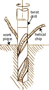
46 Tolerances Matter because parts cannot be made to an exact dimension Must specify dimension tolerance so that every part A fits every part B Higher tolerance = higher cost A ½ inch hole made on an ordinary drill press gives you a hole in the range to (+/ ). For higher precision, drill undersize and use a reamer but it will cost you more and take longer to fabricate.
47 ½ inch drill bit: +/ ½ inch reamer: ,
48 LEGOS! You can combine six 8-stud bricks of the same color 102,981,500 different ways 91% of all households with children in Denmark own LEGO products During the period , 110,000,000,000 (110 billion) LEGO elements were molded Bayer Corporation's Polymers Division is the official supplier of ABS plastic to the LEGO group. Exact specifications of the Bayer resin supplied to the LEGO Group are a closely held secret. Dimension tolerance of mold is mm ( inch)! D
49 Representing tolerances ± ±.005
50 Tolerance stack-up What is min and max height of stack?? high stack
51 Tolerance Stacking What s the tolerance (+/-) on dimension x? Ans: +/- 0.3
52 Chain or Baseline Dimensioning? You decide 1.0 ± ± ± ± ± ±.1
53 Chain or Baseline Dimensioning 1.0 ± ± ± ± ± ±.1
54 Holes and shafts 1. Will all shafts fit into all holes? 2. What is maximum clearance? hole shaft
55 ANSI standards for shaft & holes Clearance Interference Transition Shaft smaller than hole for all shafts and holes Shaft larger than hole for all shafts and holes Smallest shaft fits in largest hole Running/Sliding Force/shrink and others Basic hole Basic shaft RC1 (fit together, no play) to RC9 (fit loosely) FN1 (light drive and pressure) to FN5 (high stresses and pressures) Like Locational, etc. Use nominal size of hole as starting point Use nominal size of shaft as starting point

56 Preferred Fit Example
57 Basic Hole Tolerancing Example Drawing shows 1 in. nominal, ANSI RC4 clearance fit Basic Hole means smallest possible hole = nominal, then size shaft for clearance RC4 clearance = [0.0008, ] = [smallest hole-largest shaft, largest hole - smallest shaft]
58 Title block information for tolerance ALL DIMENSIONS IN INCHES HOLD ALL DIMENSIONS TO ± UNLESS SPECIFIED Dimension Tolerance X.X ± 0.1 X.XX ± 0.05 X.XXX ± 0.001
59 Design Detail Bent aluminum sheet, 1/16 thick A or B: Which is more expensive and why? { A B
60 Tolerance vs. Cost 1.00 ±.075 $ 1.00 ±.05 $ ±.005 $$ ± $$$$
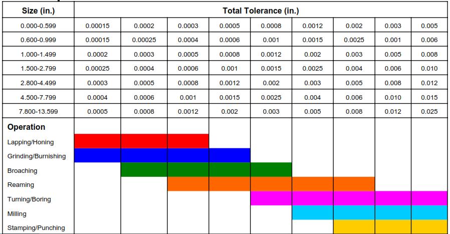
61 Manufacturing Tolerances
62 Geometric Dimensioning and Tolerancing (GD&T)
63 Traditional tolerancing is ambiguous ± ±.005??
64 Ambiguity.25 ± ± Square deviation Circular deviation
65 Geometric Dimensioning and Tolerancing.125 +/ Ideal position of hole..25, is marked with box and no +/- notation. Feature control box shows how close hole is to exact; within circular tolerance zone with diameter.01
66 Geometric Dimensioning and Tolerancing.25

67 GD&T Resources ME2011 website: mn.edu/me2011/resources Efunda tutorial: signstandards/gdt
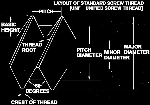
68 Threaded Fasteners What they are and how to indicate on a drawing
69 Threaded Fasteners Holes Threads Threaded fasteners

70 Holes 19 DRILL 0.75 DEEP or O DEPTH 0.75 REF Pix from unless noted
71 Thru holes 19 DRILL THRU or O.166

72 Threads
73 Threaded Fasteners (screws, bolts) Specify diameter, thread, length, head 1/4-20 x 1, RHMS 1/4" DIA 20 THREADS PER INCH 1" LONG ROUND HEAD MACHINE SCREW
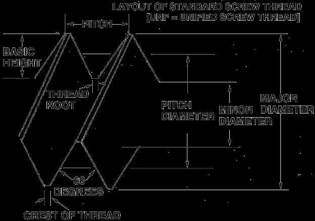
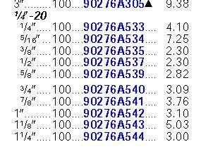
74 Common screw thread sizes Unified Thread Standard /4-20 3/8-16 1/2-13 5/8-11 3/4-10 DIA. = (N*.013) (inches)

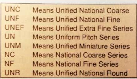
75 Alternate Thread Callout
 Round Set screw")
76 Head shapes Cap screw Pan Flat Socket head cap screw (SHCS) Round Set screw
77 Driving a fastener Slotted Hex cap Phillips Torx Hex head (Allen head)
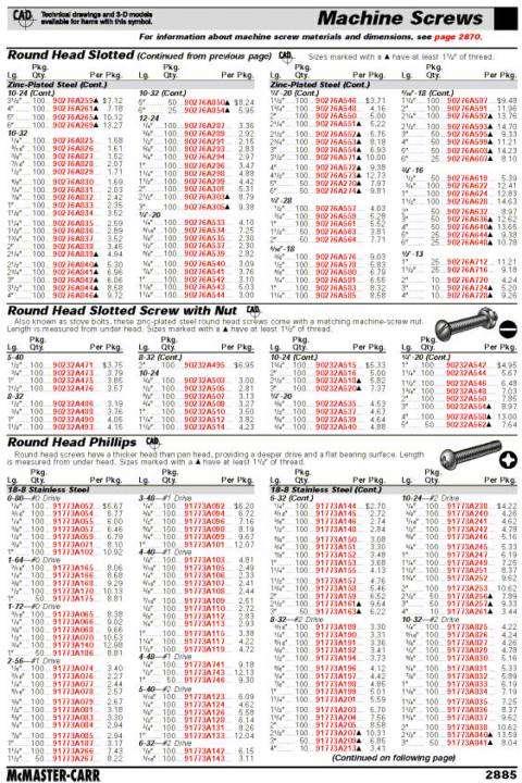
78 McMaster-Carr
79 Name the Fastener:

80 Name the Fastener: Socket Head Cap Screw Socket Head Cap Screw with counterbore
81

82 Socket Head Cap Screw with counterbore Phillips Flat Head Screw with countersink
83
84 Countersunk, Phillips Flat head Set Screw
85 Convention for screws SCHEMATIC SIMPLIFIED
86 Convention for threaded holes 6-32 THRU TOP FRONT FRONT SECTION
87 Blind threaded holes 1/2 13 x DEEP / THREAD DEPTH DRILL DEPTH

88 Countersunk holes O CSK, x 82 O

89 Counterbored holes 19 DRILL 29 CBORE, 14 DEEP C-BORE DEPTH
90
91 Other Items for Drawings
92 Leaders & notes FINISH TOP SURFACE SMOOTH NOTE B
93 TITLE BLOCKS Basic Title Name Date Units Optional Company name, sheet number, scale, tolerances, material, finish... Follow your company standards
94 MY PART W. DURFEE 10/2/2014 ALL DIMENSIONS IN INCHES
95

96 A title block using a company template
97 Production Drawings Many types of drawings can be produced from the CAD database ASSEMBLY SKETCHES SKETCHES SKETCHES MODEL DETAIL DETAIL DETAIL DETAIL DETAIL BOM MANUALS MFG PROCESS
Geometric dimensioning & tolerancing (Part 1) KCEC 1101
 KCEC 1101") Geometric dimensioning & tolerancing (Part 1) KCEC 1101 Introduction Before an object can be built, complete information about both the size and shape of the object must be available. The exact shape of
Geometric dimensioning & tolerancing (Part 1) KCEC 1101 Introduction Before an object can be built, complete information about both the size and shape of the object must be available. The exact shape of
the same information given in two different 1. Dimensions should NOT be duplicated, or Dimension Guidelines Incorrect ways.
 Dimension Guidelines 1. Dimensions should NOT be duplicated, or the same information given in two different ways. Incorrect 1. Dimensions should NOT be duplicated, or the same information given in two
ENGINEERING GRAPHICS ESSENTIALS
 ENGINEERING GRAPHICS ESSENTIALS with AutoCAD 2012 Instruction Introduction to AutoCAD Engineering Graphics Principles Hand Sketching Text and Independent Learning CD Independent Learning CD: A Comprehensive
Dimensioning. Dimensions: Are required on detail drawings. Provide the shape, size and location description: ASME Dimensioning Standards
 Dimensioning Dimensions: Are required on detail drawings. Provide the shape, size and location description: - Size dimensions - Location dimensions - Notes Local notes (specific notes) General notes ASME
DFTG-1305 Technical Drafting Prof. Francis Ha
 DFTG-1305 Technical Drafting Prof. Francis Ha Session 5 Dimensioning Geisecke s textbook: 14 th Ed. Chapter 10 p. 362 15 th Ed. Chapter 11 p. 502 Update: 17-0508 Dimensioning Part 1 of 2 Dimensioning Summary
Elementary Dimensioning
 Elementary Dimensioning Standards Institutions ANSI - American National Standards Institute - creates the engineering standards for North America. ISO - International Organization for Standardization -
Chapter 2: Dimensioning Basic Topics Advanced Topics Exercises
 Chapter 2: Dimensioning Basic Topics Advanced Topics Exercises Dimensioning: Basic Topics Summary 2-1) Detailed Drawings 2-2) Learning to Dimension 2-3) Dimension Appearance and Techniques. 2-4) Dimensioning
SOLIDWORKS 2015 and Engineering Graphics
 SOLIDWORKS 2015 and Engineering Graphics An Integrated Approach Randy H. Shih SDC PUBLICATIONS Better Textbooks. Lower Prices. www.sdcpublications.com Powered by TCPDF (www.tcpdf.org) Visit the following
Principles and Practice:
 Principles and Practice: An Integrated Approach to Engineering Graphics and AutoCAD 2014 Randy H. Shih Multimedia Disc SDC PUBLICATIONS Better Textbooks. Lower Prices. www.sdcpublications.com Video presentations
ENGINEERING GRAPHICS ESSENTIALS. (A Text and Lecture Aid) Second Edition. Kirstie Plantenberg University of Detroit Mercy SDC PUBLICATIONS
 Second Edition. Kirstie Plantenberg University of Detroit Mercy SDC PUBLICATIONS") ENGINEERING GRAPHICS ESSENTIALS (A Text and Lecture Aid) Second Edition Kirstie Plantenberg University of Detroit Mercy SDC PUBLICATIONS Schroff Development Corporation www.schroff.com www.schroff-europe.com
ENGINEERING GRAPHICS ESSENTIALS (A Text and Lecture Aid) Second Edition Kirstie Plantenberg University of Detroit Mercy SDC PUBLICATIONS Schroff Development Corporation www.schroff.com www.schroff-europe.com
and Engineering Graphics
 SOLIDWORKS 2018 and Engineering Graphics An Integrated Approach Randy H. Shih SDC PUBLICATIONS Better Textbooks. Lower Prices. www.sdcpublications.com Powered by TCPDF (www.tcpdf.org) Visit the following
Engineering Design Representation. Use of 2D drawing format: Typical Design Annotation. Standardization. Extracted drawings. General dimensions
 Engineering Design Representation Some elements of design representation not easily conveyed through model alone. Many are notational in nature. Examples are: Thread specifications Surface finishes Surface
DIMENSIONING ENGINEERING DRAWINGS
 DIMENSIONING ENGINEERING DRAWINGS An engineering drawing must be properly dimensioned in order to convey the designer s intent to the end user. Dimensions provide the information needed to specify the
Principles and Practice
 Principles and Practice An Integrated Approach to Engineering Graphics and AutoCAD 2016 Randy H. Shih SDC PUBLICATIONS Better Textbooks. Lower Prices. www.sdcpublications.com Powered by TCPDF (www.tcpdf.org)
Geometric Dimensioning and Tolerancing
 Geometric Dimensioning and Tolerancing (Known as GDT) What is GDT Helps ensure interchangeability of parts. Use is dictated by function and relationship of the part feature. It does not take the place
Dimensioning 2-4) Dimensioning and Locating Simple Features
 Dimensioning and Locating Simple Features") Dimensioning 2-4) Dimensioning and Locating Simple Features Dimensioning Features a) A circle is dimensioned by its diameter and an arc by its radius using a leader line and a note. Exercise 2-6 Circular
Dimensioning 2-4) Dimensioning and Locating Simple Features Dimensioning Features a) A circle is dimensioned by its diameter and an arc by its radius using a leader line and a note. Exercise 2-6 Circular
Tutorial: Dimensioning and Tolerances
 Tutorial: Dimensioning and Tolerances The following material addresses those dimensioning and tolerance principles necessary for you to detail the design and manufacturing processes used to make your team's
Continuous thick. Continuous thin. Continuous thin straight with zigzags. Dashed thin line. Chain thin. Chain thin double dash
 Types of line used Continuous thick Used for visible outlines and edges. Continuous thin Used for projection, dimensioning, leader lines, hatching and short centre lines. Continuous thin straight with
TECHNICAL DESIGN II (546)
") DESCRIPTION The second in a sequence of courses that prepares individuals with an emphasis in developing technical knowledge and skills to develop working drawings in support of mechanical and industrial
DESCRIPTION The second in a sequence of courses that prepares individuals with an emphasis in developing technical knowledge and skills to develop working drawings in support of mechanical and industrial
Lesson 4 Holes and Rounds
 Lesson 4 Holes and Rounds 111 Figure 4.1 Breaker OBJECTIVES Sketch arcs in sections Create a straight hole through a part Complete a Sketched hole Understand the Hole Tool Use Info to extract information
DRAFTING MANUAL. Dimensioning and Tolerancing Rules
 Page 1 1.0 General This section is in accordance with ASME Y14.5-2009 Dimensioning and Tolerancing. Note that Rule #1 is the only rule that is numbered in the 2009 standard. All of the other rules fall
Engineering Drawing Notes
 ME17 Computer Aided Design Engineering Drawing Notes Part A - 2D Drawing Principles Instructor: Mike Philpott Emeritus Associate Professor of Mechanical & Industrial Engineering Contents Part A Part B
3. The dimensioning SYMBOLS for arcs and circles should be given:
 Draft Student Name: Teacher: District: Date: Wake County Test: 9_12 T and I IC61 - Drafting I Test 2 Description: 4.08 Dimensioning Form: 501 1. The MINIMUM amount of space between two, ADJACENT DIMENSION
Glass Box Projection. Gives you 6 sides to view of an object. 10/2/14 2
 2D Drawings Glass Box Projection Gives you 6 sides to view of an object. 10/2/14 2 We can simplify this for some objects to 3 views Glass Box Approach Glass Box Approach Glass Box Approach Glass Box Approach
Student Name: Teacher: Date: District: Rowan. Assessment: 9_12 T and I IC61 - Drafting I Test 2. Description: Drafting 1 - Test 6.
 Student Name: Teacher: Date: District: Rowan Assessment: 9_12 T and I IC61 - Drafting I Test 2 Description: Drafting 1 - Test 6 Form: 501 1. 2X on a hole note means: A. Double the size of the hole. B.
Test Answers and Exam Booklet. Geometric Tolerancing
 Test Answers and Exam Booklet Geometric Tolerancing iii Contents ANSWERS TO THE GEOMETRIC TOLERANCING TEST............. 1 Part 1. Questions Part 2. Calculations SAMPLE ANSWERS TO THE GEOMETRIC TOLERANCING
1 st Subject: Types and Conventions of Dimensions and Notes
 Beginning Engineering Graphics 7 th Week Lecture Notes Instructor: Edward N. Locke Topic: Dimensions, Tolerances, Graphs and Charts 1 st Subject: Types and Conventions of Dimensions and Notes A. Definitions
Laboratory Exercises
 Laboratory Exercises 4 : 1 Lab 1A Inverted T Inverted T. Draw the solid object shown. Place the origin at the intersection of the faces with the holes in them. The front face is marked for you. Make sure
Foreword. If you have any questions about these tutorials, drop your mail to
 Foreword The main objective of these tutorials is to give you a kick start using Solidworks. The approach to write this tutorial is based on what is the most important knowledge you should know and what
Tolerancing. Summary
 Tolerancing Summary Summary What will we learn We will learn about tolerancing and how important this technique is to mass production. Key points If a feature s size is toleranced, it is allowed to vary
Copyrighted Material. Copyrighted Material. Copyrighted. Copyrighted. Material
 Engineering Graphics ORTHOGRAPHIC PROJECTION People who work with drawings develop the ability to look at lines on paper or on a computer screen and "see" the shapes of the objects the lines represent.
A Concise Introduction to Engineering Graphics
 A Concise Introduction to Engineering Graphics Fourth Edition Including Worksheet Series A Timothy J. Sexton, Professor Department of Industrial Technology Ohio University BONUS Book on CD: TECHNICAL GRAPHICS
METRIC FASTENERS 1520 METRIC FASTENERS
 1520 METRIC FASTENERS METRIC FASTENERS A number of American National Standards covering metric bolts, screws, nuts, and washers have been established in cooperation with the Department of Defense in such
Installation Instructions. Installation Type
 Installation Instructions 800 & 8050 Slide Track Door Closers Non Hold Open & Hold Open Models Note: Hold open models are not permitted to be installed in Listed fire door assemblies. PULL SIDE MOUNTED
Installation Instructions. Installation Type
 Installation Instructions 300 & 3050 Slide Track Door Closers Non Hold Open & Hold Open Models Note: Hold open models are not permitted to be installed in Listed fire door assemblies. PULL SIDE MOUNTED
CHAPTER 01 PRESENTATION OF TECHNICAL DRAWING. Prepared by: Sio Sreymean
 CHAPTER 01 PRESENTATION OF TECHNICAL DRAWING Prepared by: Sio Sreymean 2015-2016 Why do we need to study this subject? Effectiveness of Graphics Language 1. Try to write a description of this object. 2.
Geometric Tolerances & Dimensioning
 Geometric Tolerances & Dimensioning MANUFACTURING PROCESSES - 2, IE-352 Ahmed M. El-Sherbeeny, PhD KING SAUD UNIVERSITY Spring - 2015 1 Content Overview Form tolerances Orientation tolerances Location
EUROLINE CLASSIC SOLID SURFACE Installation Instructions
 EUROLINE ASSIC SOLID SURFACE Installation Instructions 12/01/15 EUROLINE ASSIC SOLID SURFACE Installation Instructions Before you begin, please note the following considerations: Safety First! Please use
2009 Academic Challenge
 2009 Academic Challenge ENGINEERING GRAPHICS TEST SECTIONAL This Test Consists of 50 Questions Engineering Graphics Test Production Team Ryan Brown, Illinois State University Author/Team Leader Kevin Devine,
Beginner s Guide to SolidWorks Alejandro Reyes, MSME Certified SolidWorks Professional and Instructor SDC PUBLICATIONS
 Beginner s Guide to SolidWorks 2008 Alejandro Reyes, MSME Certified SolidWorks Professional and Instructor SDC PUBLICATIONS Schroff Development Corporation www.schroff.com www.schroff-europe.com Part Modeling
2001 Academic Challenge
 Worldwide Youth in Science and Engineering 2001 Academic Challenge ENGINEERING GRAPHICS TEST - STATE FINALS GENERAL DIRECTIONS Engineering Graphics Test Production Team Ralph Dirksen, Western Illinois
Standards for Your Career Field
 Dimensioning Dimensions Dimensions are used to describe the sizes and relationships between features in your drawing. Dimensions are used to manufacture parts and to inspect the resulting parts to determine
Engineering Technology
 Engineering Technology Introduction to Parametric Modelling Engineering Technology 1 See Saw Exercise Part 1 Base Commands used New Part This lesson includes Sketching, Extruded Boss/Base, Hole Wizard,
9000 Level. DS-703 Page 1 of 22 3 TITLE WORK INSTRUCTIONS, GENERAL PRINT AMENDMENT
 evel DS-70 Page 1 of 22 TITE WORK INSTRUCTIONS, GENERA PRINT AMENDMENT Revision EXPANATION OF CHANGE Approvals DATE A Initial Release WB, GR 2/26/99 B C D E F G Add PMR caveat WB, GR 5/1/99 Add Surface
Question. Question. Product Features The Vocabulary of Design Download from web site. CAD/Fab Orthographic Projection 4
 Orthographic Projection Question What is the name of the feature indicated? A. Countersink B. Counterbore C. Spotface D. Hole E. Stepped hole CAD/Fab Assemblies & Mobility 2 Question Product Features The
Geometric Boundaries
 Geometric Boundaries Interpretation and Application of Geometric Dimensioning and Tolerancing (Using the Customary Inch System) Based on ASME Y14.5M-1994 Written and Illustrated by Kelly L. Bramble Published
Extra Wide Heavy Duty Plastic Lockers Series Locker Installation Instructions
 Locker Installation Instructions Thank you for selecting Extra Wide Heavy Duty Plastic Lockers. We are confident that the quality and construction of the lockers will prove to be a good investment. These
Engineering & Computer Graphics Workbook Using SOLIDWORKS
 Engineering & Computer Graphics Workbook Using SOLIDWORKS 2017 Ronald E. Barr Thomas J. Krueger Davor Juricic SDC PUBLICATIONS Better Textbooks. Lower Prices. www.sdcpublications.com Powered by TCPDF (www.tcpdf.org)
Sketching in SciTech. What you need to know for graphic communication
 Sketching in SciTech What you need to know for graphic communication Sketching in your Logbook Use pencil Take up the WHOLE PAGE Label things 1. Proportion Each part of the sketch is the right size,
ME Week 2 Project 2 Flange Manifold Part
 1 Project 2 - Flange Manifold Part 1.1 Instructions This project focuses on additional sketching methods and sketching commands. Revolve and Work features are also introduced. The part being modeled is
Installation Type. Edge of Door. Pull (Hinge) Side Mounted. Hinge Edge of Door. Push (Stop) Side Mounted
 Side Mounted. Hinge Edge of Door. Push (Stop) Side Mounted") Installation Instructions CAUTION An incorrectly installed or improperly adjusted door closer can cause property damage or personal injury. These instructions should be followed to avoid the possibility
Installation Instructions CAUTION An incorrectly installed or improperly adjusted door closer can cause property damage or personal injury. These instructions should be followed to avoid the possibility
J. La Favre Fusion 360 Lesson 2 April 19, 2017
 In this lesson, you will create a round plate with 12 counter-bored holes to fit 6-32 socket head screws. A counter-bored hole has two diameters, one to fit the threaded part of the screw and the other
ORTHOGRAPHIC PROJECTION
 ORTHOGRAPHIC PROJECTION C H A P T E R S I X OBJECTIVES 1. Recognize and the symbol for third-angle projection. 2. List the six principal views of projection. 3. Understand which views show depth in a drawing
Engineering & Computer Graphics Workbook Using SolidWorks 2014
 Engineering & Computer Graphics Workbook Using SolidWorks 2014 Ronald E. Barr Thomas J. Krueger Davor Juricic SDC PUBLICATIONS Better Textbooks. Lower Prices. www.sdcpublications.com Powered by TCPDF (www.tcpdf.org)
Chain Drive Vise. Installation Instructions. (revised 05/04/2016)
") Chain Drive Vise Installation Instructions (revised 05/04/2016) Lie-Nielsen Chain Drive Vise Instructions Table of Contents page About Your Chain Drive Vise 3 Parts List 4 Exploded Parts Diagram 5 step
Chain Drive Vise Installation Instructions (revised 05/04/2016) Lie-Nielsen Chain Drive Vise Instructions Table of Contents page About Your Chain Drive Vise 3 Parts List 4 Exploded Parts Diagram 5 step
Installation Instructions
 Installation Instructions CAUTION An incorrectly installed or improperly adjusted door closer can cause property damage or personal injury. These instructions should be followed to avoid the possibility
Dimensioning: There are a few simple best practices which can help us dimension a working drawing:
 Dimensioning and Tolerancing Prepared by: Michael Hypes Cornell University Preparation: One of the most common problems for new designers is choosing dimension that do not reflect the purpose of the part.
ENGINEERING STANDARDS SECTION: D TOG-L-LOC V-LOC OVAL-LOC LANCE-N-LOC INFORMATION. Tog-L-Loc. How The Joining Process Works
 Tog-L-Loc Tog-L-Loc is a circular, leakproof joint formed by drawing the metals into a circular "cup'' and then expanding the diameter to form a 360 radial lock below the bottom sheet. How The Joining
Geometric Boundaries II
 Geometric Boundaries II Interpretation and Application of Geometric Dimensioning and Tolerancing (Using the Inch and Metric Units) Based on ASME Y14.5-2009 (R2004) Written and Illustrated by Kelly L. Bramble
 http://blogs.solidworks.com/solidworksblog/2015/10/mbdimplementation-10-dos-and-10-donts-dont-hesitate-part-1.html Create MBE Vision Plan Identify Data Needs Assess PMI Consumption 3 DimXperts 2D Drawings
Quality Procedure QP159 General Requirements for Machined Parts
 1. PURPOSE 1.1. This procedure provides general product fabrication requirements. It also provides interpretation of certain requirements specified on product drawings, models, and electronic files. 2.
Understanding Drawings
 Chapter 3 Understanding Drawings LEARNING OBJECTIVES After studying this chapter, students will be able to: Read drawings that are dimensioned in fractional inches, decimal inches, and in metric units.
Unit4 31. UnitS 39. Unit 6 47
 Preface..................... xi About the Author......... xiii Acknowledgments... xiv Unit 1 1 Bases for Interpreting Drawings........ I Visible Lines............. 3 Lettering on Drawings... 3 Sketching...
Nut and Bolt Tutorial
 Thread Representations Nut and Bolt Tutorial Parts to a Thread Thread Dimensioning Major Diameter Thread Series (IE UNC, UNF, ACME, etc) ½ - 13 UNC 2 A or B A = External B = Internal Threads per Inch Class
Multiviews and Auxiliary Views
 Multiviews and Auxiliary Views Multiviews and Auxiliary Views Objectives Explain orthographic and multiview projection. Identifying the six principal views. Apply standard line practices to multiviews
2007 Academic Challenge
 2007 Academic Challenge ENGINEERING GRAPHICS TEST - STATE FINALS This Test Consists of 50 Questions Engineering Graphics Test Production Team Ryan Brown, Illinois State University Author/Team Coordinator
Drawing and Detailing with SolidWorks 2014
 r n fo io n at io c at tifi ar er ep c pr WT es D R u d Pcl In C S W e th W E N Drawing and Detailing with SolidWorks 2014 Referencing the ASME Y14 Engineering Drawing and Related Documentation Practices
Chain Drive Vise. Installation Instructions. (revised 11/29/2018)
") Chain Drive Vise Installation Instructions (revised 11/29/2018) Lie-Nielsen Chain Drive Vise Instructions Table of Contents page About Your Chain Drive Vise 3 Parts List 4 Exploded Parts Diagram 5 step
Chain Drive Vise Installation Instructions (revised 11/29/2018) Lie-Nielsen Chain Drive Vise Instructions Table of Contents page About Your Chain Drive Vise 3 Parts List 4 Exploded Parts Diagram 5 step
Engineering Working Drawings Basics
 Engineering Working Drawings Basics Engineering graphics is an effective way of communicating technical ideas and it is an essential tool in engineering design where most of the design process is graphically
An Improved Tool Support for a Harbor Freight Tool Grinder, version 2.2
 An Improved Tool Support for a Harbor Freight Tool Grinder, version 2.2 By R. G. Sparber Copyleft protects this document. 1 Advisory This article was written with a hobby machinist a bit above novice in
ORTHOGRAPHIC PROJECTIONS. Ms. Sicola
 ORTHOGRAPHIC PROJECTIONS Ms. Sicola Objectives List the six principal views of projection Sketch the top, front and right-side views of an object with normal, inclined, and oblique surfaces Objectives
Fastener Basics. Common Fastener Types. Fastener Materials. Grade / Class and Fastener Strength
 Fastener Basics Common Fastener Types Fastener Grade (US) or Class (metric) refers to the mechanical properties of the fastener material. Generally, a higher number indicates a stronger, more hardened
Fits and Tolerances. Prof Ahmed Kovacevic
 ME 1110 Engineering Practice 1 Engineering Drawing and Design - Lecture 7 Fits and Tolerances Prof Ahmed Kovacevic School of Engineering and Mathematical Sciences Room C130, Phone: 8780, E-Mail: a.kovacevic@city.ac.uk
7210 Surface Vertical Rod Exit Device Installation Instructions. Outside Trim
 7210 Surface Vertical Rod Exit Device Installation Instructions Top Mounting Plate (2) 1/4-20 x 3/4" PFHMS Blade Stop Block Shim (2 Supplied) Strike Plate 791 Strike (3) 10-24 x 1-1/4" PFHMS Top Latch
2016 Academic Challenge
 2016 Academic Challenge ENGINEERING GRAPHICS TEST REGIONAL This Test Consists of 40 Questions Engineering Graphics Test Production Team Ryan K. Brown, Illinois State University Author/Team Leader Mark
Specification D data models
 Previous Edition Specification 2017-04 Class: Dimensions, tolerances Class No.:01 Documentation of components by means of 3D data models 516 Part name (for databases) 2009-09 3D data models 852 005 160
SDC. SolidWorks Tutorial 2001Plus. A Competency Project Based Approach Utilizing 3D Solid Modeling. David C. Planchard & Marie P.
 2001Plus A Competency Project Based Approach Utilizing 3D Solid Modeling David C. Planchard & Marie P. Planchard SDC PUBLICATIONS www.schroff.com www.schroff-europe.com Project 2 Below are the desired
. These are not necessarily. There is much more to the, as we will see.
 Dimensioning Study Guide (Study Chapter 11 in Technical Drawing) 1. In addition to a complete shape description of an object... a drawing of the design must also give a complete ; that is, it must be.
TECHNICAL DESIGN I (540)
") DESCRIPTION The first assessment in a series, Technical Design I prepares students to develop technical knowledge and skills required to plan and prepare scale pictorial interpretations of engineering
DESCRIPTION The first assessment in a series, Technical Design I prepares students to develop technical knowledge and skills required to plan and prepare scale pictorial interpretations of engineering
INSTALLATION INSTRUCTIONS
 INSTALLATION INSTRUCTIONS HIGH PRESSUE LAMINATE (HPL) TOILET PARTITIONS 1030 TrimLineSeries 1040 DesignerSeries Includes continuous hardware option.65. IMPORTANT: Storage and Handling Information on last
Mechanical Drawing. Unit 2 Study Guide for Chapters 6-10
 Mechanical Drawing Unit 2 Study Guide for Chapters 6-10 Chapter 6 Multiview Drawing Section 6.1 Understanding Orthographic Projection A. Technical Drawing: How can a technical drawing give more accurate
Representation of features Geometric tolerances. Prof Ahmed Kovacevic
 ME 1110 Engineering Practice 1 Engineering Drawing and Design - Lecture 6 Representation of features Geometric tolerances Prof Ahmed Kovacevic School of Engineering and Mathematical Sciences Room C130,
PLTW IED MID TERM EXAM REVIEW Part A Multiple Choice
 2014-15 PLTW IED MID TERM EXAM REVIEW Part A Multiple Choice Directions: Select the letter of the response which best completes the item or answers the question. Then record your answer on the answer sheet
Solid Part Four A Bracket Made by Mirroring
 C h a p t e r 5 Solid Part Four A Bracket Made by Mirroring This chapter will cover the following to World Class standards: Sketch of a Solid Problem Draw a Series of Lines Finish the 2D Sketch Extrude
Applications of Geometric Tolerancing to Machine Design
 Applications of Geometric Tolerancing to Machine Design First Edition 1 Faryar Etesami Design for Fit Applications of Geometric Tolerancing to Machine Design First Edition Faryar Etesami Mechanical and
Basic Features. In this lesson you will learn how to create basic CATIA features. Lesson Contents: CATIA V5 Fundamentals- Lesson 3: Basic Features
 Basic Features In this lesson you will learn how to create basic CATIA features. Lesson Contents: Case Study: Basic Features Design Intent Stages in the Process Determine a Suitable Base Feature Create
INSTRUCTION SHEET U19
 U19 All Refrigerator and All Freezer Trim Kit Installation Product Line: U19 All Refrigerator and All Freezer Models Parts Included in Kit TRIMKITEZ1 (Part# 297333500): Single Trim Kit Components Single
SolidWorks 2013 Part I - Basic Tools
 SolidWorks 2013 Part I - Basic Tools Parts, Assemblies and Drawings Paul Tran CSWE, CSWI Supplemental Files SDC PUBLICATIONS Schroff Development Corporation Better Textbooks. Lower Prices. www.sdcpublications.com
INSTALLATION INSTRUCTIONS VENETIAN 84" SLIDING SHOWER DOOR SYSTEM (180º INSTALLATION)
") INSTALLATION INSTRUCTIONS VENETIAN 84" SLIDING SHOWER DO SYSTEM (180º INSTALLATION) 28539 Industry Drive, Valencia, CA 91355 Toll Free Phone: (877) 728-3874 Toll Free Fax: (888) 440-9567 Phone: (661) 775-1675
INSTALLATION INSTRUCTIONS VENETIAN 84" SLIDING SHOWER DO SYSTEM (180º INSTALLATION) 28539 Industry Drive, Valencia, CA 91355 Toll Free Phone: (877) 728-3874 Toll Free Fax: (888) 440-9567 Phone: (661) 775-1675
Contents. Notes on the use of this publication
 Contents Preface xxiii Scope Notes on the use of this publication xxv xxvi 1 Layout of drawings 1 1.1 General 1 1.2 Drawing sheets 1 1.3 Title block 2 1.4 Borders and frames 2 1.5 Drawing formats 2 1.6
.01 undercut. Ø.187 locating dowel hole (Ø.1875 x.50 pin included)
") Mold Components 1 SPRUE BUSHINGS Made of AISI 6150 material; precision ground; polished I.D. Hardened to Rc 46-50 Dowel pin hole in head for locating (pin included) Radius under head with undercut to reduce
Mold Components 1 SPRUE BUSHINGS Made of AISI 6150 material; precision ground; polished I.D. Hardened to Rc 46-50 Dowel pin hole in head for locating (pin included) Radius under head with undercut to reduce
MINI-LATHE QUICK CHANGE TOOL POST
 MINI-LATHE QUICK CHANGE TOOL POST Cutting and assembly details Machinists should familiarize themselves with the contents of this section before jumping in to the drawings. Many details are described here
Activity 7.3 Tolerances
 Page 1 of 9 Activity 7.3 Tolerances Introduction The term variation describes the degree to which an object or idea differs from others of the same type or from a standard. Examples of variation are everywhere
UNIT Lines and Symbols
 3 UNIT Lines and Symbols Various lines on a drawing have different meanings. They may appear solid, broken, thick, or thin. Each is designed to help the blueprint reader make an interpretation. The standards
EUROLINE CLASSIC PHENOLIC / EVERGREEN. Installation Instructions. Installation Instructions.
 EUROLINE ASSIC PHENOLIC / EVERGREEN EUROLINE ASSIC PHENOLIC / EVERGREEN Before you begin, please note the following considerations: Safety First! Please use proper safety gear when performing any installation.
LEG CURL IP-S1315 INSTALLATION INSTRUCTIONS
 LEG CURL IP-S35 INSTALLATION INSTRUCTIONS Copyright 2009. Star Trac by Unisen, Inc. All rights reserved, including those to reproduce this book or parts thereof in any form without first obtaining written
AutoCAD Tutor 2011 Support Docs
 AutoCAD Tutor 2011 Support Docs CHAPTER 1 CUSTOMIZING THE QUICK ACCESS TOOLBAR One of the advantages of the Quick Access Toolbar is the ability to display the AutoCAD commands that you frequently use.
Rotary Fixture M/V/X CLASS LASER SYSTEMS. Installation and Operation Instructions
 Rotary Fixture M/V/X CLASS LASER SYSTEMS Installation and Operation Instructions 02/01/2000 Introduction The Rotary Fixture controls in the Printer Driver are used along with the optional Rotary Fixture
Therma-Tru Door Gallery Setup Instructions Swing Unit with Hardware Kit - Hardware Part # MADGSWU15 (Swing Unit) Part # MADGHKSU10 (Hardware Kit)
 Part # MADGHKSU10 (Hardware Kit)") Swing Unit with Hardware Kit - Hardware Tools Included: 4mm Allen Wrench, 6mm Allen Wrench, 8mm T-Handle Allen Wrench (1) 3/4" Drill Bit, (1) 7/32" Drill Bit and Hole Template Guide Tools Required: Phillips
Swing Unit with Hardware Kit - Hardware Tools Included: 4mm Allen Wrench, 6mm Allen Wrench, 8mm T-Handle Allen Wrench (1) 3/4" Drill Bit, (1) 7/32" Drill Bit and Hole Template Guide Tools Required: Phillips
Hinge Mortising Jig. One of the make it or break it parts of building a. 6 ShopNotes No. 74
 Hinge Mortising Jig A Mortise for a Hinge. Quick, clean, and accurate that s the only way to describe the mortise you get with a trim router and this hinge mortising jig. One of the make it or break it