|
|
|
- Egbert Banks
- 5 years ago
- Views:
Transcription


1

2
3
4
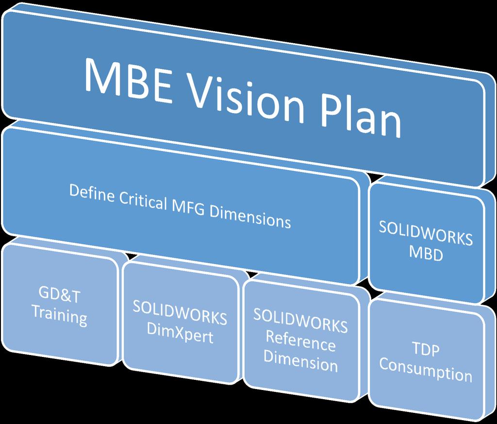
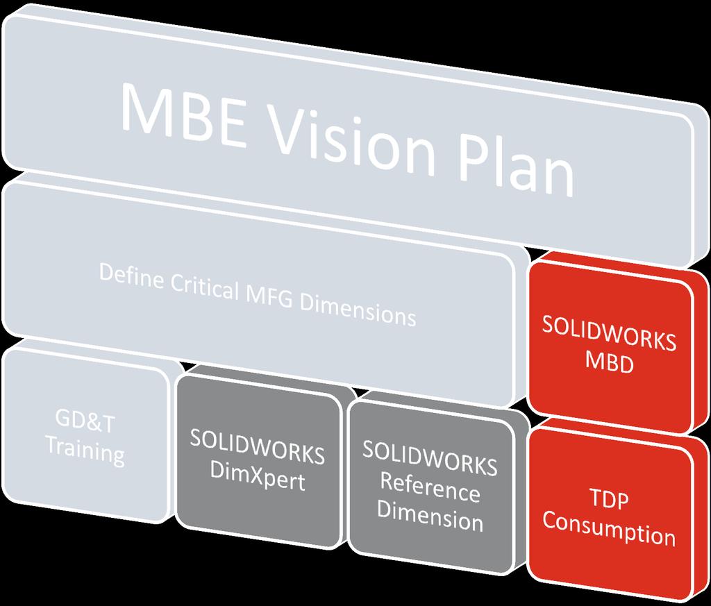
5 Create MBE Vision Plan Identify Data Needs Assess PMI Consumption
6
7
8


9 3 DimXperts 2D Drawings Introduced with version D Parts Introduced with version D Assemblies Introduced with version 2016* *SOLIDWORKS MBD license required


10 Machined Parts Milled Drilled Turned Geometric and Plus-Minus Tolerance
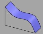
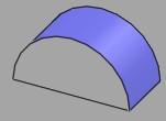
11 Sheetmetal Bends not supported --- Use Reference Dimension Prismatic type features are supported (planes, holes, slots) Molded/Casted Parts Draft not supported Profile tolerancing is supported Use reference geometry (planes and intersections) Special Geometries Including gears, threads and cams
12
13
14
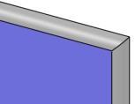
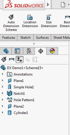
15 Hole Cone Countersink Counterbore Slot Notch Boss Cylinder Plane Pocket Surface Chamfer Fillet Width
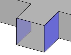
16 Intersect Plane Intersect Line Intersect Point Plane intersection between a cylinder and a cone Line intersection between a two planes Point intersection between a cylinder and a plane


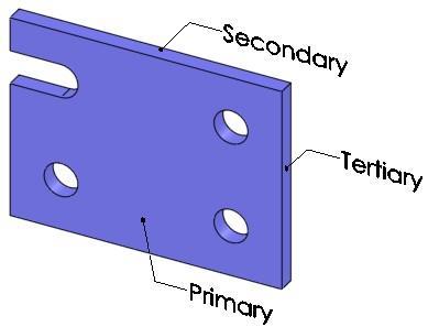
17 Model faces colored based on status Green = Fully Constrained Yellow = Under Constrained Red = Over Constrained Native Color = Not Recognized by DimXpert

18 Sketch Dimensions Facilitate part creation, configurations, design tables Linked to construction geometry not present in finished part Aren t always consistent with methods used for manufacturing Don t always meet requirements necessary to support geometric tolerancing

19


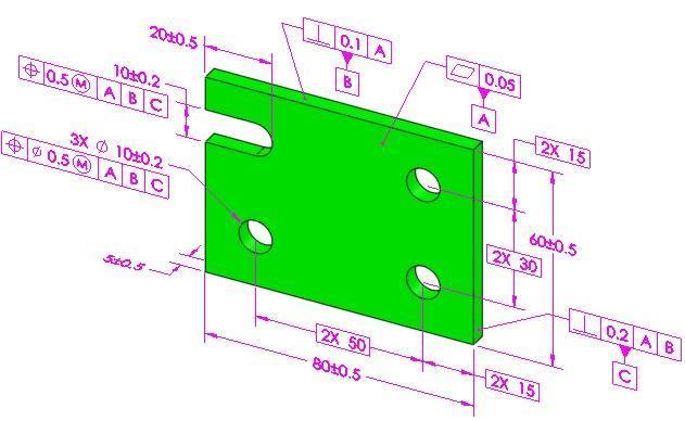
20 DimXpert Dimensions Communicate part s functional requirements for assembly, manufacturing and inspection Always associated with manufacturing features Always associated with a tolerance Dimensions (basic) associated with geometric tolerances originate from and are oriented to the datum reference frame
21


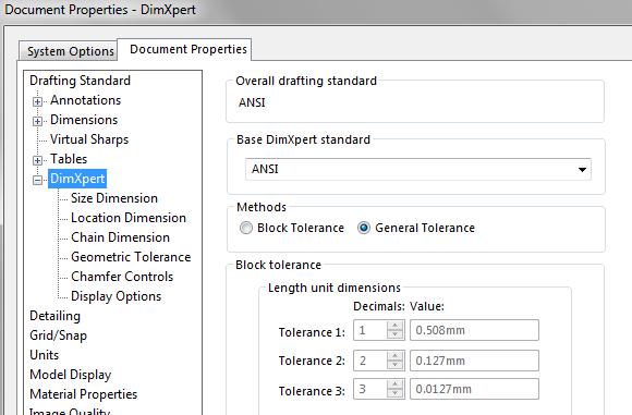
22 Tolerance type and values created by Size Dimension and Auto Dimension Scheme
23


24 Chain Baseline
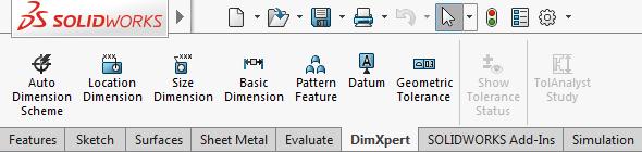
25 1. ADS (Automatic Dimensioning Scheme) and Geometric Tolerancing 2. ADS and Plus-Minus Tolerancing 3. ADS and Selected Features 4. ADS and the Wedge 5. ADS and Concentric Features 6. Feature Selector 7. Manual Tolerancing 8. More Feature Selector
26


27
28

29


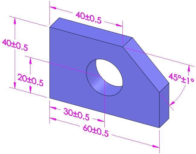
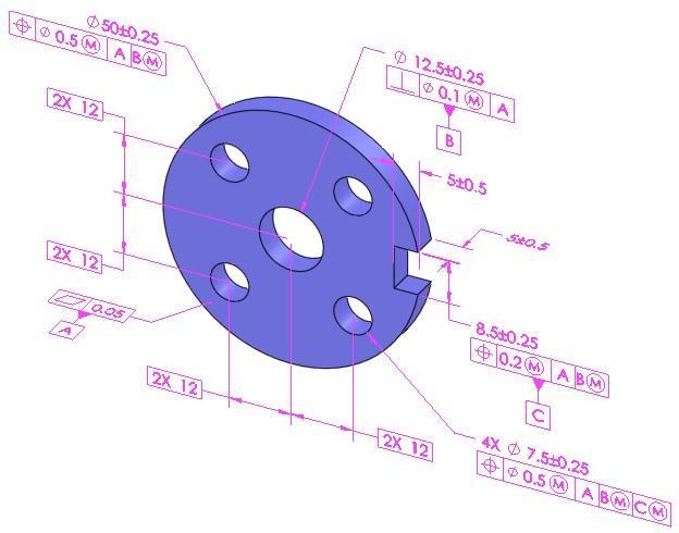
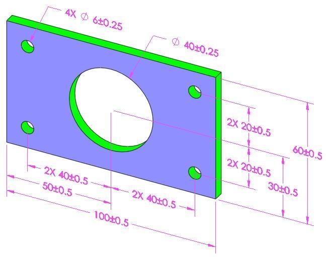
30 Plus and Minus Geometric
31


32 Location Dimension Size Dimension
33
34


35 Intersect Plane Intersect Line Intersect Point Plane intersection between a cylinder and a cone Line intersection between a two planes Point intersection between a cylinder and a plane
36 Notes BOM Title Blocks DimXpert and Reference Dimension Support in 2D Drawings
37
38
39
40
41
42
43
44
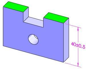
45 Tolerance stack-up analysis is the study of dimension and tolerance schemes to determine potential form, fit, and function problems in parts and assemblies Included with SOLIDWORKS Professional and Premium What the permissible gap (G) between Part1 and Part4?
 + (-42) + (-50.5) = -0.")
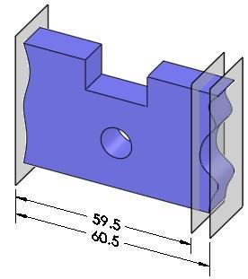
46 Assumes dimensions vary within the entire range of their tolerance zones and that the accumulation of tolerances will experience all possible variations G min = L 1 + L 2 + L 3 + L 4 + L n = L 1 + L 2 + L 3 + L 4 = (-60.75) + (-42) + (-50.5) = -0.5 Interference
47 Assumes dimensions vary randomly within a normal distribution (±3σ) centered about midpoint of the tolerance zone. G = G nominal ± T T T 32 T N 2 = 2 ± = 2 ± G min = 0.631, G max = G nominal = = 2

48 It is incorrect to think max worst case is when the parts are at their largest and min worst case is when they are at their smallest Part Nominal Assembly Worst-case Maximum Worst-case Minimum

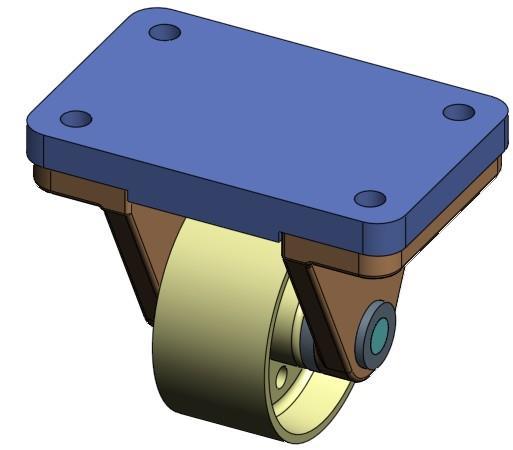
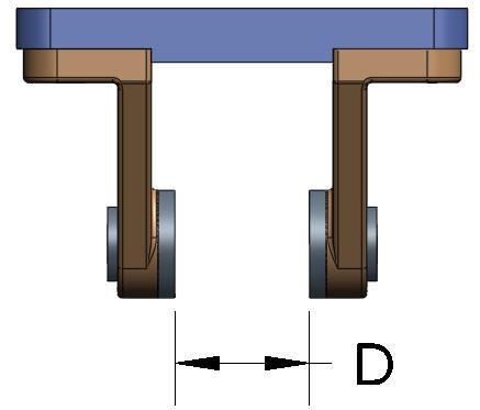
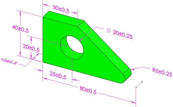
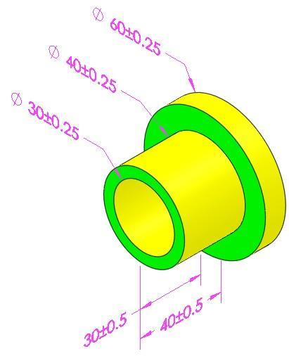
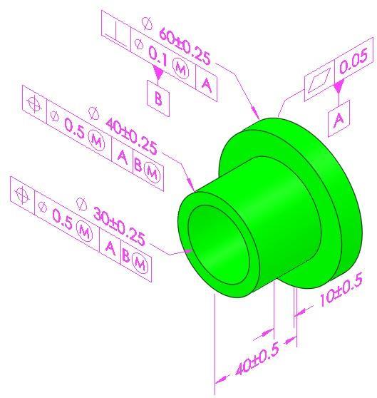
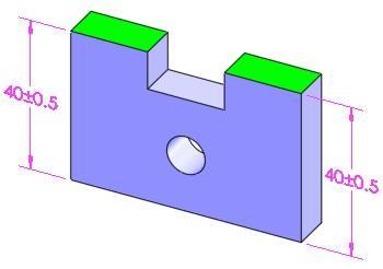
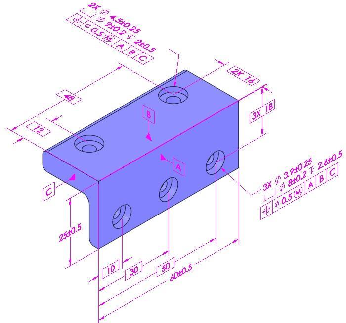
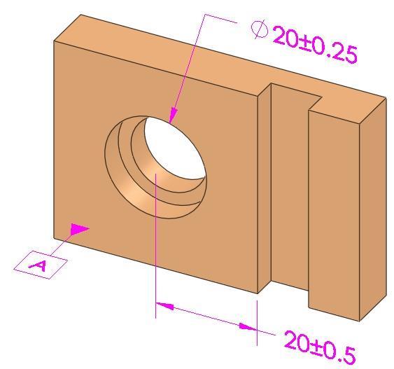
49 Functional Requirement: D >= 39

50 Top Plate Angle Bracket Bushing
51 To reduce the tolerance stack by 0.8 ( ) the tolerance of each dimension would have to be changed to ± 0.1 Before After

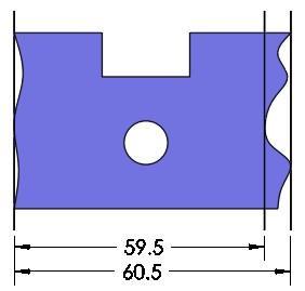
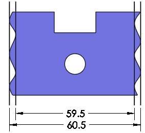
52 By increasing the width between the faces locating the two angle brackets by 1 mm the results for the minimum worst-case gap would be 39.2 ( ) Before After

53 By adding a dimension between the planes which locate the axel supports and removing the 40 dimension on the right side of the part the tolerance stack between the planes is reduced from ± 1.1 to ± 0.3. As a result the new worst-case minimum dimension would be 39. Before Before After
54
55
56
57 Create MBE Vision Plan Identify Data Needs Assess PMI Consumption
58
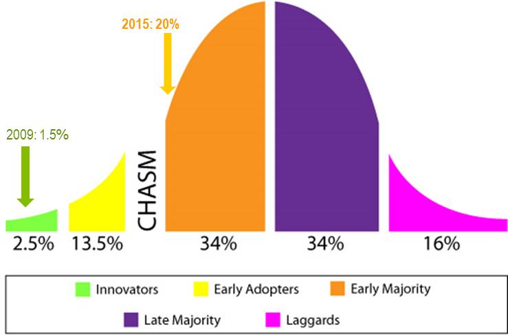
Terms The definitions of 16 critical terms defined by the 2009 standard 1
 856 SALT LAKE COURT SAN JOSE, CA 95133 (408) 251 5329 Terms The definitions of 16 critical terms defined by the 2009 standard 1 The names and definitions of many GD&T terms have very specific meanings.
Product and Manufacturing Information (PMI)
") Product and Manufacturing Information (PMI) 1 Yadav Virendrasingh Sureshnarayan, 2 R.K.Agrawal 1 Student of ME in Product Design and Development,YTCEM -Bhivpuri road-karjat, Maharastra 2 HOD Mechanical
Product and Manufacturing Information (PMI) 1 Yadav Virendrasingh Sureshnarayan, 2 R.K.Agrawal 1 Student of ME in Product Design and Development,YTCEM -Bhivpuri road-karjat, Maharastra 2 HOD Mechanical
the same information given in two different 1. Dimensions should NOT be duplicated, or Dimension Guidelines Incorrect ways.
 Dimension Guidelines 1. Dimensions should NOT be duplicated, or the same information given in two different ways. Incorrect 1. Dimensions should NOT be duplicated, or the same information given in two
Product and Manufacturing Information(PMI)
") Product and Manufacturing Information(PMI) Ravi Krishnan V 1 Post Graduate Student Department of Mechanical Engineering Veermata Jijabai Technological Institute Mumbai, India ravi.krishnan30@gmail.com
Product and Manufacturing Information(PMI) Ravi Krishnan V 1 Post Graduate Student Department of Mechanical Engineering Veermata Jijabai Technological Institute Mumbai, India ravi.krishnan30@gmail.com
Geometric Tolerances & Dimensioning
 Geometric Tolerances & Dimensioning MANUFACTURING PROCESSES - 2, IE-352 Ahmed M. El-Sherbeeny, PhD KING SAUD UNIVERSITY Spring - 2015 1 Content Overview Form tolerances Orientation tolerances Location
SolidWorks Part I - Basic Tools SDC. Includes. Parts, Assemblies and Drawings. Paul Tran CSWE, CSWI
 SolidWorks 2015 Part I - Basic Tools Includes CSWA Preparation Material Parts, Assemblies and Drawings Paul Tran CSWE, CSWI SDC PUBLICATIONS Better Textbooks. Lower Prices. www.sdcpublications.com Powered
ME 114 Engineering Drawing II
 ME 114 Engineering Drawing II FITS, TOLERANCES and SURFACE QUALITY MARKS Mechanical Engineering University of Gaziantep Dr. A. Tolga Bozdana Assistant Professor Tolerancing Tolerances are used to control
Dimensioning: There are a few simple best practices which can help us dimension a working drawing:
 Dimensioning and Tolerancing Prepared by: Michael Hypes Cornell University Preparation: One of the most common problems for new designers is choosing dimension that do not reflect the purpose of the part.
Teach Yourself UG NX Step-by-Step
 Teach Yourself UG NX Step-by-Step By Hui Zhang Ph.D., P.Eng. www.geocities.com/zhanghui1998 Table of Contents Chapter 1 Introduction... 1 1.1 UG NX User Interface... 1 1.2 Solid Modeling Fundamentals...
Geometric dimensioning & tolerancing (Part 1) KCEC 1101
 KCEC 1101") Geometric dimensioning & tolerancing (Part 1) KCEC 1101 Introduction Before an object can be built, complete information about both the size and shape of the object must be available. The exact shape of
Geometric dimensioning & tolerancing (Part 1) KCEC 1101 Introduction Before an object can be built, complete information about both the size and shape of the object must be available. The exact shape of
Geometric Boundaries
 Geometric Boundaries Interpretation and Application of Geometric Dimensioning and Tolerancing (Using the Customary Inch System) Based on ASME Y14.5M-1994 Written and Illustrated by Kelly L. Bramble Published
Course Summary. CLASSROOM: On-site Instructor-led Education WEBINAR: Instructor-led On-line Training ON-DEMAND: Virtual Self-Paced Learning
 Course Summary CLASSROOM: On-site Instructor-led Education WEBINAR: Instructor-led On-line Training ON-DEMAND: Virtual Self-Paced Learning NO. COURSE NAME CLASSROOM* WEBINAR ON-DEMAND MBD/MBE EDUCATION
1.0 What is tolerance analysis? 2.0 What is Tolerance Stackup? 3.0 Generally, the Tolerance Stackup Process 4.0 Method and Types of Tolerance
 TOLERANCE ANALYSIS 1.0 What is tolerance analysis? 2.0 What is Tolerance Stackup? 3.0 Generally, the Tolerance Stackup Process 4.0 Method and Types of Tolerance Analysis 5.0 Worst-case Tolerance Stackup
Unit4 31. UnitS 39. Unit 6 47
 Preface..................... xi About the Author......... xiii Acknowledgments... xiv Unit 1 1 Bases for Interpreting Drawings........ I Visible Lines............. 3 Lettering on Drawings... 3 Sketching...
SOLIDWORKS 2018 Basic Tools
 SOLIDWORKS 2018 Basic Tools Getting Started with Parts, Assemblies and Drawings Paul Tran CSWE, CSWI SDC PUBLICATIONS Better Textbooks. Lower Prices. www.sdcpublications.com Powered by TCPDF (www.tcpdf.org)
Machinist NOA (2010) Subtask to Unit Comparison
 Subtask to Unit Comparison") Machinist NOA (2010) Subtask to Unit Comparison NOA Subtask Task 1 Organizes work. 1.01 Interprets documentation. A16 Job Planning 1.02 Plans sequence of operations. A16 Job Planning 1.03 Maintains safe
Machinist NOA (2010) Subtask to Unit Comparison NOA Subtask Task 1 Organizes work. 1.01 Interprets documentation. A16 Job Planning 1.02 Plans sequence of operations. A16 Job Planning 1.03 Maintains safe
SolidWorks 2014 Part I - Basic Tools
 SolidWorks 2014 Part I - Basic Tools Parts, Assemblies and Drawings Paul Tran CSWE, CSWI SDC PUBLICATIONS Better Textbooks. Lower Prices. www.sdcpublications.com Powered by TCPDF (www.tcpdf.org) Visit
Single Part Tolerance Analysis 1
 856 SALT LAKE COURT SAN JOSE, CA 95133 (408) 251 5329 Single Part Tolerance Analysis 1 2X Ø.250 ±.005 D 3.075-3.175.500 2.000.250 ±.005 E.375 C 2.050 1.950.609.859 1.375 G 1.125 B.375.750 1.125 1.500 1.875
A Concise Introduction to Engineering Graphics
 A Concise Introduction to Engineering Graphics Fourth Edition Including Worksheet Series A Timothy J. Sexton, Professor Department of Industrial Technology Ohio University BONUS Book on CD: TECHNICAL GRAPHICS
SOLIDWORKS 2017 Basic Tools
 SOLIDWORKS 2017 Basic Tools Getting Started with Parts, Assemblies and Drawings Paul Tran CSWE, CSWI SDC PUBLICATIONS Better Textbooks. Lower Prices. www.sdcpublications.com Powered by TCPDF (www.tcpdf.org)
Mechanical Drawing. Unit 2 Study Guide for Chapters 6-10
 Mechanical Drawing Unit 2 Study Guide for Chapters 6-10 Chapter 6 Multiview Drawing Section 6.1 Understanding Orthographic Projection A. Technical Drawing: How can a technical drawing give more accurate
SolidWorks 2013 Part I - Basic Tools
 SolidWorks 2013 Part I - Basic Tools Parts, Assemblies and Drawings Paul Tran CSWE, CSWI Supplemental Files SDC PUBLICATIONS Schroff Development Corporation Better Textbooks. Lower Prices. www.sdcpublications.com
Dimensioning. Dimensions: Are required on detail drawings. Provide the shape, size and location description: ASME Dimensioning Standards
 Dimensioning Dimensions: Are required on detail drawings. Provide the shape, size and location description: - Size dimensions - Location dimensions - Notes Local notes (specific notes) General notes ASME
ANSI ORIFICE FLANGES METAL-KOREA
 METAL-KOREA ANSI ORIFICE FLANGES ORIFICE FLANGES are widely used in conjunction with orifice meters for measuring the rate of flow of liquids and gases. They are basically the same as standard welding
Test Answers and Exam Booklet. Geometric Tolerancing
 Test Answers and Exam Booklet Geometric Tolerancing iii Contents ANSWERS TO THE GEOMETRIC TOLERANCING TEST............. 1 Part 1. Questions Part 2. Calculations SAMPLE ANSWERS TO THE GEOMETRIC TOLERANCING
Basic Features. In this lesson you will learn how to create basic CATIA features. Lesson Contents: CATIA V5 Fundamentals- Lesson 3: Basic Features
 Basic Features In this lesson you will learn how to create basic CATIA features. Lesson Contents: Case Study: Basic Features Design Intent Stages in the Process Determine a Suitable Base Feature Create
DRAFTING MANUAL. Dimensioning and Tolerancing Rules
 Page 1 1.0 General This section is in accordance with ASME Y14.5-2009 Dimensioning and Tolerancing. Note that Rule #1 is the only rule that is numbered in the 2009 standard. All of the other rules fall
Geometric Boundaries II
 Geometric Boundaries II Interpretation and Application of Geometric Dimensioning and Tolerancing (Using the Inch and Metric Units) Based on ASME Y14.5-2009 (R2004) Written and Illustrated by Kelly L. Bramble
SOLIDWORKS 2015 and Engineering Graphics
 SOLIDWORKS 2015 and Engineering Graphics An Integrated Approach Randy H. Shih SDC PUBLICATIONS Better Textbooks. Lower Prices. www.sdcpublications.com Powered by TCPDF (www.tcpdf.org) Visit the following
Improving Manufacturability
 Improving Manufacturability GD&T is a Tool Not a Weapon Joe Soistman Quality Manufacturing Solutions, LLC Overview What is manufacturability, and why is it important? Overview What is manufacturability,
NIST MBE PMI Validation & Conformance Testing CTC Model Verification Results February 2015
 YOUR CENTRAL SOURCE FOR DATA EXCHANGE NIST MBE PMI Validation & Conformance Testing CTC Model Verification Results February 2015 Doug Cheney CAD Validation Specialist ITI TranscenData Doug.Cheney@TranscenData.com
Table of Contents. Dedication Preface. Chapter 1: Introduction to CATIA V5-6R2015. Chapter 2: Drawing Sketches in the Sketcher Workbench-I.
 Table of Contents Dedication Preface iii xvii Chapter 1: Introduction to CATIA V5-6R2015 Introduction to CATIA V5-6R2015 1-2 CATIA V5 Workbenches 1-2 System Requirements 1-4 Getting Started with CATIA
Geometric Tolerancing
 Geometric Tolerancing Distorted Objects by Suzy Lelievre Scale Transform SALOME Geometry User s Guide: Scale Transform Baek-Ki-Kim-Twisted Stool Mesh Geometric Tolerancing What is it? Geometric Tolerancing
Specification D data models
 Previous Edition Specification 2017-04 Class: Dimensions, tolerances Class No.:01 Documentation of components by means of 3D data models 516 Part name (for databases) 2009-09 3D data models 852 005 160
A Brief Introduction to Engineering Graphics. Will Durfee & Tim Kowalewski Department of Mechanical Engineering University of Minnesota
 A Brief Introduction to Engineering Graphics Will Durfee & Tim Kowalewski Department of Mechanical Engineering University of Minnesota Opening comments Engineering graphics is the method for documenting
University of Bath Department of Mechanical Engineering Design for FDM Rapid Prototyping Manufacture (Basic)
") University of Bath BATH BA2 7AY United Kingdom Tel +44 (0)1225 388388 University of Bath Department of Mechanical Engineering Design for FDM Rapid Prototyping Manufacture (Basic) Prepared by... E Sells
University of Bath BATH BA2 7AY United Kingdom Tel +44 (0)1225 388388 University of Bath Department of Mechanical Engineering Design for FDM Rapid Prototyping Manufacture (Basic) Prepared by... E Sells
Starting a 3D Modeling Part File
 1 How to Create a 3D Model and Corresponding 2D Drawing with Dimensions, GDT (Geometric Dimensioning and Tolerance) Symbols and Title Block in SolidWorks 2013-2014 By Edward Locke This tutorial will introduce
and Engineering Graphics
 SOLIDWORKS 2018 and Engineering Graphics An Integrated Approach Randy H. Shih SDC PUBLICATIONS Better Textbooks. Lower Prices. www.sdcpublications.com Powered by TCPDF (www.tcpdf.org) Visit the following
Concentricity and Symmetry Controls
 Concentricity and Symmetry Controls Alessandro Anzalone, Ph.D. Hillsborough Community College, Brandon Campus Concentricity and Symmetry Controls Sections: 1. Concentricity Control 2. Symmetry Control
Geometric Dimensioning and Tolerancing
 Geometric dimensioning and tolerancing (GDT) is Geometric Dimensioning and Tolerancing o a method of defining parts based on how they function, using standard ASME/ANSI symbols; o a system of specifying
Representation of features Geometric tolerances. Prof Ahmed Kovacevic
 ME 1110 Engineering Practice 1 Engineering Drawing and Design - Lecture 6 Representation of features Geometric tolerances Prof Ahmed Kovacevic School of Engineering and Mathematical Sciences Room C130,
Geometric Dimensioning and Tolerancing
 Geometric Dimensioning and Tolerancing (Known as GDT) What is GDT Helps ensure interchangeability of parts. Use is dictated by function and relationship of the part feature. It does not take the place
Activity Bracket
 Activity 1.5.6 Bracket Introduction Studying how an object is fastened is not something you do every day. But, just for fun, consider looking at how your desk or your locker is held together. Most likely,
G D & T - Overview. Natarajan R. EGS Computers India Private Limited. Director. *
 G D & T - Overview Natarajan R Director www.egs.co.in * www.egsindia.com EGS Computers India Private Limited Agenda Introduction to GD & T DimXpert for GD & T G D & T by examples Benefits of G D & T What
HOW TO REVIEW A CETOL 6σ ANALYSIS Presented by Dan Lange, Manager - Services
 HOW TO REVIEW A CETOL 6σ ANALYSIS Presented by Dan Lange, Manager - Services Abstract Reviewing a CETOL 6σ analysis requires a comprehensive understanding of the assembly being studied and the capabilities
Creo Parametric & Creo Parametric 2.0
 51 Creo Parametric & Creo Parametric 2.0 Watch the Project Lecture Video before you start Angle Block Complete after Lesson 4 52 Figure Angle Block 1 Angle Block Angle Block This lesson project is a simple
EGS Computers India Private Limited Chennai, Coimbatore, Trichy
 White Paper on Geometric Dimensioning & Tolerancing with Tolerance Stack-Up Analysis EGS Computers India Private Limited Chennai, Coimbatore, Trichy Web: www.egsindia.com info@egs.co.in Tel: 044-2480 3370
Spokane Public Schools Course: Drafting and Design Technology
 Spokane Public Schools Drafting and Design Technology Course: Drafting and Design Technology Total Framework Hours up to: 180 hours CIP Code: 140102 Exploratory Preparatory Date Last Modified: 4/2/2015
Contents. Notes on the use of this publication
 Contents Preface xxiii Scope Notes on the use of this publication xxv xxvi 1 Layout of drawings 1 1.1 General 1 1.2 Drawing sheets 1 1.3 Title block 2 1.4 Borders and frames 2 1.5 Drawing formats 2 1.6
To help understand the 3D annotations, the book includes a complete tutorial on SOLIDWORKS MBD
 To help understand the 3D annotations, the book includes a complete tutorial on SOLIDWORKS MBD Technical product documentation using ISO GPS - ASME GD&T standards FOREWORD Designers create perfect and
FOREWORD. Technical product documentation using ISO GPS - ASME GD&T standards
 Technical product documentation using ISO GPS - ASME GD&T standards FOREWORD Designers create perfect and ideal geometries through drawings or by means of Computer Aided Design systems, but unfortunately
ENGINEERING GRAPHICS ESSENTIALS
 ENGINEERING GRAPHICS ESSENTIALS with AutoCAD 2012 Instruction Introduction to AutoCAD Engineering Graphics Principles Hand Sketching Text and Independent Learning CD Independent Learning CD: A Comprehensive
Drawing and Detailing with SolidWorks 2014
 r n fo io n at io c at tifi ar er ep c pr WT es D R u d Pcl In C S W e th W E N Drawing and Detailing with SolidWorks 2014 Referencing the ASME Y14 Engineering Drawing and Related Documentation Practices
Software Development & Education Center NX 8.5 (CAD CAM CAE)
") Software Development & Education Center NX 8.5 (CAD CAM CAE) Detailed Curriculum Overview Intended Audience Course Objectives Prerequisites How to Use This Course Class Standards Part File Naming Seed
Software Development & Education Center NX 8.5 (CAD CAM CAE) Detailed Curriculum Overview Intended Audience Course Objectives Prerequisites How to Use This Course Class Standards Part File Naming Seed
Fits and Tolerances. Prof Ahmed Kovacevic
 ME 1110 Engineering Practice 1 Engineering Drawing and Design - Lecture 7 Fits and Tolerances Prof Ahmed Kovacevic School of Engineering and Mathematical Sciences Room C130, Phone: 8780, E-Mail: a.kovacevic@city.ac.uk
Training Guide Basics
 Training Guide Basics 2014, Missler Software. 7, Rue du Bois Sauvage F-91055 Evry, FRANCE Web: www.topsolid.com E-mail: info@topsolid.com All rights reserved. TopSolid Design Basics This information is
GETTING YOUR DIGITAL HOUSE IN ORDER
 GETTING YOUR DIGITAL HOUSE IN ORDER STREAMLINING THE MBD AND DETAILING PROCESS WITH CREO Martin Neumüller Creo Product Management PTC Eindhoven, 2017 AGENDA 1. MBD opportunities and challenges 2. Creo
Essentials of SOLIDWORKS 2015 (4+ Days) * Ve-I Bonus! * File Management + SimulationXpress
 * Ve-I Bonus! * File Management + SimulationXpress") Essentials of SOLIDWORKS 2015 (4+ Days) * Ve-I Bonus! * File Management + SimulationXpress Overview What is SOLIDWORKS? Interface Tour View Manipulation Provides some background info on the SOLIDWORKS
Essentials of SOLIDWORKS 2015 (4+ Days) * Ve-I Bonus! * File Management + SimulationXpress Overview What is SOLIDWORKS? Interface Tour View Manipulation Provides some background info on the SOLIDWORKS
Alessandro Anzalone, Ph.D. Hillsborough Community College, Brandon Campus
 Alessandro Anzalone, Ph.D. Hillsborough Community College, Brandon Campus Sections: 1. Definitions 2. Material Conditions 3. Modifiers 4. Radius and Controlled Radius 5. Introduction to Geometric Tolerances
CAD-CAM-CAE Examples
 CAD-CAM-CAE Examples example title: example number: example level: CAx system: Related material part with TÁMOP Job Description: Shaft type component (CAD) ÓE-A06a basic - medium - advanced CATIA v5 CAD
Autodesk Inventor. In Engineering Design & Drafting. By Edward Locke
 Autodesk Inventor In Engineering Design & Drafting By Edward Locke Engineering Design Drafting Essentials Working Drawings: Orthographic Projection Views (multi-view, auxiliary view, details and sections)
ADA Curriculum for Pre-Engineering Students Correlation Guide
 ADA Curriculum for Pre-Engineering Students Correlation Guide Madsen/Autodesk Inventor 7: Basics Through Advanced Note: The concepts presented in the ADA Curriculum are covered in the text as they pertain
Quality Procedure QP159 General Requirements for Machined Parts
 1. PURPOSE 1.1. This procedure provides general product fabrication requirements. It also provides interpretation of certain requirements specified on product drawings, models, and electronic files. 2.
Datum reference frame Position and shape tolerances Tolerance analysis
 Datum reference frame Position and shape tolerances Tolerance analysis Šimon Kovář Datum reference frame Datum reference frames are typically for 3D. A typical datum reference frame is made up of three
9000 Level. DS-703 Page 1 of 22 3 TITLE WORK INSTRUCTIONS, GENERAL PRINT AMENDMENT
 evel DS-70 Page 1 of 22 TITE WORK INSTRUCTIONS, GENERA PRINT AMENDMENT Revision EXPANATION OF CHANGE Approvals DATE A Initial Release WB, GR 2/26/99 B C D E F G Add PMR caveat WB, GR 5/1/99 Add Surface
AC : CALCULATION OF TOLERANCE STACKS USING DIRECT-POSITION APPROACH IN GEOMETRIC DIMENSIONING AND TOLERANCING
 AC 2009-138: CALCULATION OF TOLERANCE STACKS USING DIRECT-POSITION APPROACH IN GEOMETRIC DIMENSIONING AND TOLERANCING Cheng Lin, Old Dominion University American Society for Engineering Education, 2009
TECHNICAL DESIGN II (546)
") DESCRIPTION The second in a sequence of courses that prepares individuals with an emphasis in developing technical knowledge and skills to develop working drawings in support of mechanical and industrial
DESCRIPTION The second in a sequence of courses that prepares individuals with an emphasis in developing technical knowledge and skills to develop working drawings in support of mechanical and industrial
1. Create a 2D sketch 2. Create geometry in a sketch 3. Use constraints to position geometry 4. Use dimensions to set the size of geometry
 2.1: Sketching Many features that you create in Fusion 360 start with a 2D sketch. In order to create intelligent and predictable designs, a good understanding of how to create sketches and how to apply
What s New In SA CHAPTER
 What s New In SA CHAPTER 2 One of the advantages of SpatialAnalyzer is that development occurs at a brisk pace. New feature requests, bug fixes, and changes are implemented quickly, giving you the opportunity
Tolerancing Fixed Fasteners 1
 + 856 SALT LAKE COURT SAN JOSE, CA 951 (408) 251 529 Tolerancing Fixed Fasteners 1.274- Figure 8-5 Fixed fastener The fixed fastener in Fig. 8-5 is fixed by one or more of the members being fastened. The
DFTG-1305 Technical Drafting Prof. Francis Ha
 DFTG-1305 Technical Drafting Prof. Francis Ha Session 5 Dimensioning Geisecke s textbook: 14 th Ed. Chapter 10 p. 362 15 th Ed. Chapter 11 p. 502 Update: 17-0508 Dimensioning Part 1 of 2 Dimensioning Summary
Bottom Rail. Chapter 2. Chair. A. Weldments Toolbar. Step 1. Click File Menu > New, click Part and OK. B. 3D Sketch.
 Chapter 2 Chair Bottom Rail A. Weldments Toolbar. Step 1. Click File Menu > New, click Part and OK. Step 2. Right click Sketch on the Command Manager toolbar and select Weldments, Fig. 1. Step 3. Click
PolyWorks Inspector Standard. 3 Day Course
 PolyWorks Inspector Standard INTRODUCTION TO POLYWORKS Workspace Manager Basic Options File and Project Structures PolyWorks License Manager INTRODUCTION TO POLYWORKS INSPECTOR User Interface Basic Options
Advanced Dimensional Management LLC
 Index: Mechanical Tolerance Stackup and Analysis Bryan R. Fischer Accuracy and precision 8-9 Advanced Dimensional Management 14, 21, 78, 118, 208, 251, 286, 329-366 Ambiguity 4, 8-14 ASME B89 48 ASME Y14.5M-1994
Education Curriculum Combined Specialist
 Education Curriculum Combined Specialist Invest your time in imagining next generation designs. Here s what we will teach you to give shape to your imagination. CATIA Combined Specialist Course CATIA Mechanical
1 st Subject: Types and Conventions of Dimensions and Notes
 Beginning Engineering Graphics 7 th Week Lecture Notes Instructor: Edward N. Locke Topic: Dimensions, Tolerances, Graphs and Charts 1 st Subject: Types and Conventions of Dimensions and Notes A. Definitions
Engineering drawing. Semester I/II Mechanical Engineering Department Technical University of Gdańsk. Lecture 8
 Engineering drawing Semester I/II Mechanical Engineering Department Technical University of Gdańsk Lecture 8 Representing Tolerance Values Tolerance is the total amount a dimension may vary and is the
GEOMETRICAL TOLERANCING
 GEOMETRICAL TOLERANCING Introduction In a typical engineering design and production environment, the designer of a part rarely follows the design to the shop floor, and consequently the only means of communication
CATIA Instructor-led Live Online Training Program
 Course Outline Introduction & Understanding to CATIA Environment Introduction & Understanding to CATIA interface Starting new file Understand the Sketcher workbench of CATIA V5 Start a new file in the
Objectives. Inventor Part Modeling MA 23-1 Presented by Tom Short, P.E. Munro & Associates, Inc
 Objectives Inventor Part Modeling MA 23-1 Presented by Tom Short, P.E. Munro & Associates, Inc To demonstrate most of the sketch tools and part features in : Inventor Release 6 And, to show logical techniques
Manufacturing Processes (2), IE-352 Ahmed M El-Sherbeeny, PhD Spring Manual Process Planning
, IE-352 Ahmed M El-Sherbeeny, PhD Spring Manual Process Planning") Manufacturing Processes (2), IE-352 Ahmed M El-Sherbeeny, PhD Spring 2017 Manual Process Planning Chapter Outline 2 1. Introduction 2. Manual Process Planning 3. Process Plan 4. Part Features Identification
Manufacturing Processes (2), IE-352 Ahmed M El-Sherbeeny, PhD Spring 2017 Manual Process Planning Chapter Outline 2 1. Introduction 2. Manual Process Planning 3. Process Plan 4. Part Features Identification
David A. Madsen. Faculty Emeritus
 i Q eometric ' ' Dimensioning andtolerancing Ninth Edition Based on ASME Y14.5-2009 AWk A ejacy ofjejtccftence APPROVED PUBLICATION by David A. Madsen President, Madsen Designs Inc. www.madsendesigns.com
Tutorial: Dimensioning and Tolerances
 Tutorial: Dimensioning and Tolerances The following material addresses those dimensioning and tolerance principles necessary for you to detail the design and manufacturing processes used to make your team's
Elementary Dimensioning
 Elementary Dimensioning Standards Institutions ANSI - American National Standards Institute - creates the engineering standards for North America. ISO - International Organization for Standardization -
Introduction to CATIA V5
 Introduction to CATIA V5 Release 17 (A Hands-On Tutorial Approach) Kirstie Plantenberg University of Detroit Mercy SDC PUBLICATIONS Schroff Development Corporation www.schroff.com Better Textbooks. Lower
Feature-Based Modeling and Optional Advanced Modeling. ENGR 1182 SolidWorks 05
 Feature-Based Modeling and Optional Advanced Modeling ENGR 1182 SolidWorks 05 Today s Objectives Feature-Based Modeling (comprised of 2 sections as shown below) 1. Breaking it down into features Creating
Chair. Bottom Rail. on the Command Manager. on the Weldments toolbar.
 Chapter 2 Chair Bottom Rail A. Weldments Toolbar. Step 1. Click File Menu > New, click Part and OK. Step 2. Right click Sketch on the Command Manager toolbar and select Weldments, Fig. 1. Step 3. Click
Introduction to GD&T Session 2: Rules and Concepts of GD&T
 Introduction to GD&T Session 2: Rules and Concepts of GD&T An exploration of the language known as Geometric Dimensioning and Tolerancing Instructor: John-Paul Belanger Review Benefits of GD&T The GD&T
Dual clip mould In the following exercise you will create a full 2 cavity mould of your dual clip mould component.
 Dual clip mould 2018 In the following exercise you will create a full 2 cavity mould of your dual clip mould component. The mould is required to be a 2 cavity mould and must contain all the necessary detail
FACULTY OF ENGINEERING DESIGN AND PRODUCTION ENGINEERING DEPARTMENT. Credit Hour System Metrology Lab 1 MDP 240. Sine Bars. Metrology laboratory
 FACULTY OF ENGINEERING DESIGN AND PRODUCTION ENGINEERING DEPARTMENT Report On: Credit Hour System Metrology Lab 1 MDP 240 (13) Sine Bars Metrology laboratory Class No: B.N. Student Name Remark Signature
Purdue AFL. CATIA CAM Process Reference Rev. B
 Purdue AFL CATIA CAM Process Reference Rev. B Revision Notes Revision - of this document refers to the CATIA v5r21 deployment of the AFL CATIA Environment. All information contained in this reference document
COURSE CONTENTS FOR THE AVTS COURSES
 Revision: 00 LEARNING CONTENT Page 1 of 14 COURSE CONTENTS FOR THE AVTS COURSES AT CAD- CAM LAB, ATI, VIDYANAGAR, HYDERABAD Revision: 00 LEARNING CONTENT Page 2 of 14 III COURSE CODE CAD-01 IV COURSE TITLE
ENGINEERING GRAPHICS ESSENTIALS. (A Text and Lecture Aid) Second Edition. Kirstie Plantenberg University of Detroit Mercy SDC PUBLICATIONS
 Second Edition. Kirstie Plantenberg University of Detroit Mercy SDC PUBLICATIONS") ENGINEERING GRAPHICS ESSENTIALS (A Text and Lecture Aid) Second Edition Kirstie Plantenberg University of Detroit Mercy SDC PUBLICATIONS Schroff Development Corporation www.schroff.com www.schroff-europe.com
ENGINEERING GRAPHICS ESSENTIALS (A Text and Lecture Aid) Second Edition Kirstie Plantenberg University of Detroit Mercy SDC PUBLICATIONS Schroff Development Corporation www.schroff.com www.schroff-europe.com
J. La Favre Fusion 360 Lesson 2 April 19, 2017
 In this lesson, you will create a round plate with 12 counter-bored holes to fit 6-32 socket head screws. A counter-bored hole has two diameters, one to fit the threaded part of the screw and the other
From the above fig. After sketching the path and profile select the sweep command First select the profile from property manager tree And then select
 Chapter 5 In sweep command there is a) Two sketch profiles b) Two path c) One sketch profile and one path The sweep profile is used to create threads springs circular things and difficult geometry. For
MODELS FOR GEOMETRIC PRODUCT SPECIFICATION
 U.P.B. Sci. Bull., Series D, Vol. 70, No.2, 2008 ISSN 1454-2358 MODELS FOR GEOMETRIC PRODUCT SPECIFICATION Ionel SIMION 1 Lucrarea prezintă câteva modele pentru verificarea asistată a geometriei pieselor,
Using Advanced GDT Analysis to Further Reduce Rejects and Improve Rework Time and Instructions
 Using Advanced GDT Analysis to Further Reduce Rejects and Improve Rework Time and Instructions 3 rd TRI-NATIONAL WORKSHOP AND MEETING OF THE NORTH AMERICAN COORDINATE METROLOGY ASSOCIATION 3D Measurement
2009 Academic Challenge
 2009 Academic Challenge ENGINEERING GRAPHICS TEST STATE FINALS This Test Consists of 50 Questions Engineering Graphics Test Production Team Ryan Brown, Illinois State University Author/Team Leader Kevin
CHAPTER 01 PRESENTATION OF TECHNICAL DRAWING. Prepared by: Sio Sreymean
 CHAPTER 01 PRESENTATION OF TECHNICAL DRAWING Prepared by: Sio Sreymean 2015-2016 Why do we need to study this subject? Effectiveness of Graphics Language 1. Try to write a description of this object. 2.