Standards for Your Career Field
|
|
|
- Muriel Carmel Warner
- 6 years ago
- Views:
Transcription
1 Dimensioning
2 Dimensions Dimensions are used to describe the sizes and relationships between features in your drawing. Dimensions are used to manufacture parts and to inspect the resulting parts to determine if they are acceptable. Drawings with dimensions and notes often serve as construction documents and legal contracts. ANSI Y14.5M-1994 is the current standard. Other standards may apply.

3 Standards for Your Career Field Standards are different in different career areas. Most of the examples in this course will be of mechanical parts. Civil, Electrical, Construction, and other areas follow similar practices, but sometimes with less need for precision in measurements. Dimensioned drawings are a part of a contractual document.
4 Vocabulary Dimension line, Extension line, Leader, Dimension offset or gap, Centerline, Finish mark, Dimension value Baseline dimensioning, Chained dimensioning
5 Tolerance Definition: The total allowable variation an acceptable part can have from the specified dimension. The less variation allowed, the more the part will cost to make.

6 3 Things for Good Dimensioning Good technique of dimensioning Good choice of dimensions Good placement of dimensions
7 Dimensioning Technique describes how the dimensions in your drawing should look. defined by various standards like ANSI Y help you create dimensions that are plainly visible and can be easily interpreted. specifies sizes for creating dimensions relative to the paper size of your final plot.
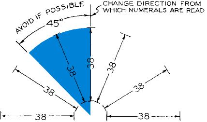
8 Orientation for Dimension Values Unidirectional: read horizontally from bottom of sheet Aligned: align with dimension line and read from bottom or right side of sheet
9 Unidirectional Orientation
10 Aligned Orientation
11 Aligned Dimensions
12 Stagger Dimension Values
13 Dimension & Extension Lines
14 Finish Marks
15 Choice of Dimensions the dimensions you specify determine the way the the part is manufactured and the way the tolerance is applied consider the purpose of the part and its function in the assembly consider how easy it will be to check the measurement on the actual part fully dimension each part do not overdimension, each dimensions should appear only once
16 Choosing Which Dimensions to Show Don t overdimension Give the diameter of circular shapes, the radius of arcs. No redundant or superfluous dimensions Give size dimensions for features. Give location dimensions to show how features relate to one another.
17 Mating Dimensions
18 Effect of Tolerance on Dimensioning Chained each dimension continues from the previous one tolerances stack Baseline each dimension is specified from a common baseline tolerances do not stack
19 Units Fractional Inch Decimal inch dimensions are typically specified to 2 decimal places. Metric values are typically given in whole millimeters or to one decimal place.


20 Placement of Dimensions Rules-of-thumb for dimension placement help ensure that others will be able to interpret your drawing Where placement practices conflict, remember that your goal is to clearly communicate the purpose of the drawing. Use the practice you feel will make the drawing easy to understand.
21 Placement Practices Avoid dimensioning on object. Avoid dimensioning to hidden lines. Place dimensions between views when possible. Don t float dimensions. Group dimensions around a central view. Place dimensions where feature shows shape. Dimension from or between machined surfaces Give overall dimensions where possible. Don t dimension to rectangular view centerlines.
22 Dimensioning Prisms
23 Dimensioning Cylinders
24 Dimensioning Holes
25 Using Diameter Symbol
26 Locating Holes
27 Coordinate Dimensioning
28 Summary Good dimensioning is a combination of choosing dimensions which reflect your design intent, proper technique in creating the details of the dimension line, extension line, arrowheads and dimension values, and placing the dimensions on the drawing so that they can be read clearly. Dimensioning drawings correctly can be as important or more important than drawing the shapes correctly. Good dimensioning requires practice and thought!
29 Where to get more information Refer to examples in your textbook ASME, ANSI, ISO, and other organizations publish standards. Talk to people in manufacturing. Their experience is valuable in helping you keep the cost of the product down by specifying reasonable tolerances and up-to-date manufacturing processes.
3. The dimensioning SYMBOLS for arcs and circles should be given:
 Draft Student Name: Teacher: District: Date: Wake County Test: 9_12 T and I IC61 - Drafting I Test 2 Description: 4.08 Dimensioning Form: 501 1. The MINIMUM amount of space between two, ADJACENT DIMENSION
Student Name: Teacher: Date: District: Rowan. Assessment: 9_12 T and I IC61 - Drafting I Test 2. Description: Drafting 1 - Test 6.
 Student Name: Teacher: Date: District: Rowan Assessment: 9_12 T and I IC61 - Drafting I Test 2 Description: Drafting 1 - Test 6 Form: 501 1. 2X on a hole note means: A. Double the size of the hole. B.
Elementary Dimensioning
 Elementary Dimensioning Standards Institutions ANSI - American National Standards Institute - creates the engineering standards for North America. ISO - International Organization for Standardization -
DFTG-1305 Technical Drafting Prof. Francis Ha
 DFTG-1305 Technical Drafting Prof. Francis Ha Session 5 Dimensioning Geisecke s textbook: 14 th Ed. Chapter 10 p. 362 15 th Ed. Chapter 11 p. 502 Update: 17-0508 Dimensioning Part 1 of 2 Dimensioning Summary
. These are not necessarily. There is much more to the, as we will see.
 Dimensioning Study Guide (Study Chapter 11 in Technical Drawing) 1. In addition to a complete shape description of an object... a drawing of the design must also give a complete ; that is, it must be.
Chapter 2: Dimensioning Basic Topics Advanced Topics Exercises
 Chapter 2: Dimensioning Basic Topics Advanced Topics Exercises Dimensioning: Basic Topics Summary 2-1) Detailed Drawings 2-2) Learning to Dimension 2-3) Dimension Appearance and Techniques. 2-4) Dimensioning
the same information given in two different 1. Dimensions should NOT be duplicated, or Dimension Guidelines Incorrect ways.
 Dimension Guidelines 1. Dimensions should NOT be duplicated, or the same information given in two different ways. Incorrect 1. Dimensions should NOT be duplicated, or the same information given in two
Dimensioning. Dimensions: Are required on detail drawings. Provide the shape, size and location description: ASME Dimensioning Standards
 Dimensioning Dimensions: Are required on detail drawings. Provide the shape, size and location description: - Size dimensions - Location dimensions - Notes Local notes (specific notes) General notes ASME
Geometric dimensioning & tolerancing (Part 1) KCEC 1101
 KCEC 1101") Geometric dimensioning & tolerancing (Part 1) KCEC 1101 Introduction Before an object can be built, complete information about both the size and shape of the object must be available. The exact shape of
Geometric dimensioning & tolerancing (Part 1) KCEC 1101 Introduction Before an object can be built, complete information about both the size and shape of the object must be available. The exact shape of
DIMENSIONING ENGINEERING DRAWINGS
 DIMENSIONING ENGINEERING DRAWINGS An engineering drawing must be properly dimensioned in order to convey the designer s intent to the end user. Dimensions provide the information needed to specify the
1 st Subject: Types and Conventions of Dimensions and Notes
 Beginning Engineering Graphics 7 th Week Lecture Notes Instructor: Edward N. Locke Topic: Dimensions, Tolerances, Graphs and Charts 1 st Subject: Types and Conventions of Dimensions and Notes A. Definitions
ENGINEERING GRAPHICS ESSENTIALS. (A Text and Lecture Aid) Second Edition. Kirstie Plantenberg University of Detroit Mercy SDC PUBLICATIONS
 Second Edition. Kirstie Plantenberg University of Detroit Mercy SDC PUBLICATIONS") ENGINEERING GRAPHICS ESSENTIALS (A Text and Lecture Aid) Second Edition Kirstie Plantenberg University of Detroit Mercy SDC PUBLICATIONS Schroff Development Corporation www.schroff.com www.schroff-europe.com
ENGINEERING GRAPHICS ESSENTIALS (A Text and Lecture Aid) Second Edition Kirstie Plantenberg University of Detroit Mercy SDC PUBLICATIONS Schroff Development Corporation www.schroff.com www.schroff-europe.com
C H A P T E R E L E V E N
 DIMENSIONING C H A P T E R E L E V E N Giesecke, Hill, Spencer, Dygdon, Novak, Lockhart, Goodman 1 OBJECTIVES 1. Use conventional dimensioning techniques to describe size and shape accurately on an engineering
Dimensioning 2-4) Dimensioning and Locating Simple Features
 Dimensioning and Locating Simple Features") Dimensioning 2-4) Dimensioning and Locating Simple Features Dimensioning Features a) A circle is dimensioned by its diameter and an arc by its radius using a leader line and a note. Exercise 2-6 Circular
Dimensioning 2-4) Dimensioning and Locating Simple Features Dimensioning Features a) A circle is dimensioned by its diameter and an arc by its radius using a leader line and a note. Exercise 2-6 Circular
Dimension Styles. EDT Chapter 18 - Basic Dimensioning Practices 1
 Dimension Styles EDT 310 - Chapter 18 - Basic Dimensioning Practices 1 Dimension Styles The appearance of dimensions is controlled by over 70 different settings. Dimension Styles are saved configurations
Dimensioning in the figure below could be improved by: A
 1-Multiview-study Page 1 of 8 irections For Numbers 1-53 : Read each of the following multiple-choice items and the possible answers carefully. Mark the letter of the correct answer on your answer sheet
Technical Drawing 101 with AutoCAD 2018
 Technical Drawing 101 with AutoCAD 2018 A Multidisciplinary Guide to Drafting Theory and Practice with Video Instruction Douglas Smith Antonio Ramirez Ashleigh Fuller SDC PUBLICATIONS Better Textbooks.
Engineering Working Drawings Basics
 Engineering Working Drawings Basics Engineering graphics is an effective way of communicating technical ideas and it is an essential tool in engineering design where most of the design process is graphically
CHAPTER 01 PRESENTATION OF TECHNICAL DRAWING. Prepared by: Sio Sreymean
 CHAPTER 01 PRESENTATION OF TECHNICAL DRAWING Prepared by: Sio Sreymean 2015-2016 Why do we need to study this subject? Effectiveness of Graphics Language 1. Try to write a description of this object. 2.
UNIT Lines and Symbols
 3 UNIT Lines and Symbols Various lines on a drawing have different meanings. They may appear solid, broken, thick, or thin. Each is designed to help the blueprint reader make an interpretation. The standards
An Introduction to Dimensioning Dimension Elements-
 An Introduction to Dimensioning A precise drawing plotted to scale often does not convey enough information for builders to construct your design. Usually you add annotation showing object measurements
Below are the desired outcomes and usage competencies based on the completion of Project 4.
 Engineering Design with SolidWorks Project 4 Below are the desired outcomes and usage competencies based on the completion of Project 4. Project Desired Outcomes: An understanding of the customer s requirements
TECHNICAL DESIGN I (540)
") DESCRIPTION The first assessment in a series, Technical Design I prepares students to develop technical knowledge and skills required to plan and prepare scale pictorial interpretations of engineering
DESCRIPTION The first assessment in a series, Technical Design I prepares students to develop technical knowledge and skills required to plan and prepare scale pictorial interpretations of engineering
Geometric Dimensioning and Tolerancing
 Geometric Dimensioning and Tolerancing (Known as GDT) What is GDT Helps ensure interchangeability of parts. Use is dictated by function and relationship of the part feature. It does not take the place
CAD and Drafting Standards Working Drawings
 CAD and Drafting Standards Working Drawings Gregory Mocko Introduction 2 The purpose of drawing or generating a CAD document is to communicate Essentially, since communication is the goal, some standards
A Concise Introduction to Engineering Graphics
 A Concise Introduction to Engineering Graphics Fourth Edition Including Worksheet Series A Timothy J. Sexton, Professor Department of Industrial Technology Ohio University BONUS Book on CD: TECHNICAL GRAPHICS
2004 Academic Challenge
 2004 Academic Challenge ENGINEERING GRAPHICS TEST - SECTIONAL Engineering Graphics Test Production Team Ryan Brown, Illinois State University Author/Team Coordinator Kevin Devine, Illinois State University
Copyrighted Material. Copyrighted Material. Copyrighted. Copyrighted. Material
 Engineering Graphics ORTHOGRAPHIC PROJECTION People who work with drawings develop the ability to look at lines on paper or on a computer screen and "see" the shapes of the objects the lines represent.
Dimensioning the Rectangular Problem
 C h a p t e r 3 Dimensioning the Rectangular Problem In this chapter, you will learn the following to World Class standards: 1. Creating new layers in an AutoCAD drawing 2. Placing Centerlines on the drawing
Making an Architectural Drawing Template
 C h a p t e r 8 Addendum: Architectural Making an Architectural Drawing Template In this chapter, you will learn the following to World Class standards:! Starting from Scratch for the Last time! Creating
CAD Mechanical Design I
 EXAM INFORMATION Items 58 Points 85 Prerequisites NONE Course Length ONE SEMESTER Career Cluster ARCHITECTURE AND CONSTRUCTION MANUFACTURING SCIENCE, TECHNOLOGY, ENGINEERING AND MATHEMATICS Performance
Activity 7.1 More Dimensioning
 Activity 7.1 More Dimensioning Introduction The basic standard dimensioning method established by the American National Standards Institute and the American Society of Mechanical Engineers (ANSI or ASME)
Test Answers and Exam Booklet. Geometric Tolerancing
 Test Answers and Exam Booklet Geometric Tolerancing iii Contents ANSWERS TO THE GEOMETRIC TOLERANCING TEST............. 1 Part 1. Questions Part 2. Calculations SAMPLE ANSWERS TO THE GEOMETRIC TOLERANCING
2003 Academic Challenge
 Worldwide Youth in Science and Engineering 2003 Academic Challenge ENGINEERING GRAPHICS TEST - SECTIONAL Engineering Graphics Test Production Team Ryan Brown, Illinois State University Author/Team Coordinator
2012 Academic Challenge
 2012 Academic Challenge ENGINEERING GRAPHICS TEST SECTIONAL This Test Consists of 40 Questions Engineering Graphics Test Production Team Ryan Brown, Illinois State University Author/Team Leader Jacob Borgerson,
EN1740 Computer Aided Visualization and Design Spring /16/2012 Brian C. P. Burke
 EN1740 Computer Aided Visualization and Design Spring 2012 2/16/2012 Brian C. P. Burke Last Time: Measuring within Pro/E 2D representation Orthographic projection 3 rd Angle vs. 1 st Angle Creating engineering
Geometric Boundaries
 Geometric Boundaries Interpretation and Application of Geometric Dimensioning and Tolerancing (Using the Customary Inch System) Based on ASME Y14.5M-1994 Written and Illustrated by Kelly L. Bramble Published
Shaft Hanger - SolidWorks
 ME-430 INTRODUCTION TO COMPUTER AIDED DESIGN Shaft Hanger - SolidWorks BY: DR. HERLI SURJANHATA ASSIGNMENT Submit TWO isometric views of the Shaft Hanger with your report, 1. Shaded view of the trimetric
AutoCAD Tutor 2011 Support Docs
 AutoCAD Tutor 2011 Support Docs CHAPTER 1 CUSTOMIZING THE QUICK ACCESS TOOLBAR One of the advantages of the Quick Access Toolbar is the ability to display the AutoCAD commands that you frequently use.
Chapter 8. Technical Drawings
 Chapter 8 Technical Drawing Technical Drawings Multiview drawings Also called three-view drawings Simple objects take three views Front, top, one side Title block Identifies who did the design Gives date,
Tolerancing. Summary
 Tolerancing Summary Summary What will we learn We will learn about tolerancing and how important this technique is to mass production. Key points If a feature s size is toleranced, it is allowed to vary
Drawing and Detailing with SolidWorks 2014
 r n fo io n at io c at tifi ar er ep c pr WT es D R u d Pcl In C S W e th W E N Drawing and Detailing with SolidWorks 2014 Referencing the ASME Y14 Engineering Drawing and Related Documentation Practices
Geometric Boundaries II
 Geometric Boundaries II Interpretation and Application of Geometric Dimensioning and Tolerancing (Using the Inch and Metric Units) Based on ASME Y14.5-2009 (R2004) Written and Illustrated by Kelly L. Bramble
GEOMETRIC DIMENSIONING AND TOLERANCING (GD&T)
") GEOMETRIC DIMENSIONING AND TOLERANCING (GD&T) Based on ASME Y14.5M-1994 Standard Duration : 4 days Time : 9:00am 5:00pm Methodology : Instructor led Presentation, exercises and discussion Target : Individuals
GEOMETRIC DIMENSIONING AND TOLERANCING (GD&T) Based on ASME Y14.5M-1994 Standard Duration : 4 days Time : 9:00am 5:00pm Methodology : Instructor led Presentation, exercises and discussion Target : Individuals
A Brief Introduction to Engineering Graphics. Will Durfee & Tim Kowalewski Department of Mechanical Engineering University of Minnesota
 A Brief Introduction to Engineering Graphics Will Durfee & Tim Kowalewski Department of Mechanical Engineering University of Minnesota Opening comments Engineering graphics is the method for documenting
Geometric Tolerances & Dimensioning
 Geometric Tolerances & Dimensioning MANUFACTURING PROCESSES - 2, IE-352 Ahmed M. El-Sherbeeny, PhD KING SAUD UNIVERSITY Spring - 2015 1 Content Overview Form tolerances Orientation tolerances Location
Engineering Design. with SolidWorks A Step-by-Step Project Based Approach Utilizing 3D Solid Modeling
 INSIDE: MultiMedia CD An audio/visual presentation of the tutorial projects Engineering Design with SolidWorks 2010 A Step-by-Step Project Based Approach Utilizing 3D Solid Modeling Introductory Level
Making an Architectural Drawing Template
 C h a p t e r 8 Addendum: Architectural Making an Architectural Drawing Template In this chapter, you will learn the following to World Class standards: 1. Starting from Scratch 2. Creating New Layers
2012 Academic Challenge
 2012 Academic Challenge ENGINEERING GRAPHICS TEST STATE FINAL This Test Consists of 40 Questions Engineering Graphics Test Production Team Ryan Brown, Illinois State University Author/Team Leader Jacob
Test Code: 8294 / Version 1
 Pennsylvania Customized Assessment Blueprint Test Code: 8294 / Version 1 Copyright 2014. All Rights Reserved. General Assessment Information Blueprint Contents General Assessment Information Written Assessment
Introduction to Engineering Design
 Introduction to Engineering Design Final Examination Spring 2005 Answer Key Parts A, B & C For Teacher Use ONLY Part A Scoring Conversion Chart Raw Converted Raw Converted Raw Converted Raw Converted 1
SOLIDWORKS 2015 and Engineering Graphics
 SOLIDWORKS 2015 and Engineering Graphics An Integrated Approach Randy H. Shih SDC PUBLICATIONS Better Textbooks. Lower Prices. www.sdcpublications.com Powered by TCPDF (www.tcpdf.org) Visit the following
Brief Introduction to Engineering Graphics The use of drawings to convey information. Sketching freehand straight edge
 Brief Introduction to Engineering Graphics The use of drawings to convey information. Sketching freehand straight edge CAD drawings 2D drafting 3D model to 2D drawings 1 Different Graphical Representation
Engineering Design with SolidWorks A Step-by-Step Project Based Approach Utilizing 3D Solid Modeling. David C. Planchard & Marie P.
 Engineering Design with SolidWorks 2003 A Step-by-Step Project Based Approach Utilizing 3D Solid Modeling David C. Planchard & Marie P. Planchard SDC PUBLICATIONS www.schroff.com www.schroff-europe.com
ENGINEERING DRAWING LECTURE 4
 ENGINEERING DRAWING LECTURE 4 Conventions Convention or Code: The representation of any matter by some sign or mark on the drawing is known as convention or code. The convention make the drawing simple
UNIT 5a STANDARD ORTHOGRAPHIC VIEW DRAWINGS
 UNIT 5a STANDARD ORTHOGRAPHIC VIEW DRAWINGS 5.1 Introduction Orthographic views are 2D images of a 3D object obtained by viewing it from different orthogonal directions. Six principal views are possible
1994 Dimensioning & Tolerancing
 ASME Y14.5M-1994 1994 Dimensioning & Tolerancing The new scanning generation Zeiss / Applied Geometrics, Inc. Applied Geometrics, Inc. Copyright 2003 1 Zeiss Carl Zeiss is one of the world's leading enterprises
Aircraft Drawing and Blueprint Reading
 Aircraft Drawing and Blueprint Reading Course Introduction Types of drawings Engineering also known as production or working drawings. Block diagram Types of Drawings Schematics Sketches Charts and graphs
Principles and Practice:
 Principles and Practice: An Integrated Approach to Engineering Graphics and AutoCAD 2014 Randy H. Shih Multimedia Disc SDC PUBLICATIONS Better Textbooks. Lower Prices. www.sdcpublications.com Video presentations
and Engineering Graphics
 SOLIDWORKS 2018 and Engineering Graphics An Integrated Approach Randy H. Shih SDC PUBLICATIONS Better Textbooks. Lower Prices. www.sdcpublications.com Powered by TCPDF (www.tcpdf.org) Visit the following
Las Vegas, Nevada November 27-30, 2001
 Las Vegas, Nevada November 27-30, 2001 Speaker Name: Phil Leverault Course Title: Conquering Dimensions Course ID: Course Outline: Factors to Consider for Dimension Styles Discipline Mechanical Dimensioning
Drawing and Detailing with SolidWorks. A Workbook for SolidWorks 2001/2001Plus. by David C. Planchard and Marie P. Planchard
 Drawing and Detailing with SolidWorks A Workbook for SolidWorks 2001/2001Plus by David C. Planchard and Marie P. Planchard A Competency Based Approach Referencing the ASME Y14 Engineering Drawing and Related
Principles and Practice
 Principles and Practice An Integrated Approach to Engineering Graphics and AutoCAD 2016 Randy H. Shih SDC PUBLICATIONS Better Textbooks. Lower Prices. www.sdcpublications.com Powered by TCPDF (www.tcpdf.org)
ASME Y14.5M-1994 GD&T Certification Preparation Examination
 ASME Y14.5M-1994 GD&T Certification Preparation Examination Directions: On the response sheet on the last page, fill in the circle of the letter which best completes the following statements. Do not write
Dimensioning: There are a few simple best practices which can help us dimension a working drawing:
 Dimensioning and Tolerancing Prepared by: Michael Hypes Cornell University Preparation: One of the most common problems for new designers is choosing dimension that do not reflect the purpose of the part.
Geometric Dimensioning & Tolerancing
 Western Technical College 31420350 Geometric Dimensioning & Tolerancing Course Outcome Summary Course Information Description Career Cluster Instructional Level Total Credits 1.00 Total Hours 36.00 Recognition
Dimensioning the Bracket Problem
 C h a p t e r 11 Dimensioning the Bracket Problem In this chapter, you will learn the following to World Class standards: 1. Dimensioning a Multiple View Drawing 2. Placing Center Marks on a Multiple View
Trade of Metal Fabrication. Module 3: Plate Fabrication Unit 12: Duct Sections Phase 2
 Trade of Metal Fabrication Module 3: Plate Fabrication Unit 12: Duct Sections Phase 2 Table of Contents List of Figures... 4 List of Tables... 5 Document Release History... 6 Module 3 Plate Fabrication...
2004 Academic Challenge
 2004 Academic Challenge ENGINEERING GRAPHICS TEST - REGIONAL Engineering Graphics Test Production Team Ryan Brown, Illinois State University Author/Team Coordinator Kevin Devine, Illinois State University
Applications of Geometric Tolerancing to Machine Design
 Applications of Geometric Tolerancing to Machine Design First Edition 1 Faryar Etesami Design for Fit Applications of Geometric Tolerancing to Machine Design First Edition Faryar Etesami Mechanical and
Drawing and Detailing
 Drawing and Detailing with SolidWorks 2007 By David C. Planchard and Marie P. Planchard Referencing the ASME Y14 Engineering Drawing and Related Documentation Practices SDC PUBLICATIONS Schroff Development
X11-Using the New Civil Geometry Tools
 X11-Using the New Civil Geometry Tools Joe Waxmonsky, PE Bentley Civil 2010 Bentley Systems, Incorpo ora 2010 Bentley Systems, Incorpora 2010 Nordic Civil Geometry 2 WWW.BENTLEY.COM Roads and Bridges 2010
TECHNICAL DESIGN II (546)
") DESCRIPTION The second in a sequence of courses that prepares individuals with an emphasis in developing technical knowledge and skills to develop working drawings in support of mechanical and industrial
DESCRIPTION The second in a sequence of courses that prepares individuals with an emphasis in developing technical knowledge and skills to develop working drawings in support of mechanical and industrial
User Guide V10 SP1 Addendum
 Alibre Design User Guide V10 SP1 Addendum Copyrights Information in this document is subject to change without notice. The software described in this document is furnished under a license agreement or
Making a Drawing Template
 C h a p t e r 8 Addendum: Metric Making a Drawing Template In this chapter, you will learn the following to World Class standards: 1. Starting from Scratch 2. Creating New Layers in an progecad Drawing
GUIDELINES FOR DRAFTING
 UNIT 1 GUIDELINES FOR DRAFTING 1.1 Introduction The term draughting is used to describe the language of drafting in this book. It defines the terminology, symbology, conventions, and standards used in
Cluster Block Housings and Contacts
 Cluster Block Housings and Contacts Application Specification 114-2019 20 SEP 17 Rev J NOTE i All numerical values are in metric units [with U.S. customary units in brackets]. Dimensions are in millimeters
Contents. Notes on the use of this publication
 Contents Preface xxiii Scope Notes on the use of this publication xxv xxvi 1 Layout of drawings 1 1.1 General 1 1.2 Drawing sheets 1 1.3 Title block 2 1.4 Borders and frames 2 1.5 Drawing formats 2 1.6
Advanced Dimensional Management LLC
 Index for Tolerance Stackup, Tolerance Analysis and Tolerancing Manual: Plus and Minus Edition Accuracy and precision 3, 19 Ambiguity 20 ASME Y14.5M-1994 2 rule #1 2 Assembly Process 20, 28, 79-81 Assembly
GEOMETRIC DIMENSIONING AND TOLERANCING (GD&T) Based on ASME Y14.5M-1994 Standard
 Based on ASME Y14.5M-1994 Standard") GEOMETRIC DIMENSIONING AND TOLERANCING (GD&T) Based on ASME Y14.5M-1994 Standard Duration: 4 Days Training Course Content: Day 1: Tolerancing in Engineering Drawing (9:00am-10:00am) 1.0 Geometric Dimensioning
GEOMETRIC DIMENSIONING AND TOLERANCING (GD&T) Based on ASME Y14.5M-1994 Standard Duration: 4 Days Training Course Content: Day 1: Tolerancing in Engineering Drawing (9:00am-10:00am) 1.0 Geometric Dimensioning
IED Detailed Outline. Unit 1 Design Process Time Days: 16 days. An engineering design process involves a characteristic set of practices and steps.
 IED Detailed Outline Unit 1 Design Process Time Days: 16 days Understandings An engineering design process involves a characteristic set of practices and steps. Research derived from a variety of sources
Question. Question. Product Features The Vocabulary of Design Download from web site. CAD/Fab Orthographic Projection 4
 Orthographic Projection Question What is the name of the feature indicated? A. Countersink B. Counterbore C. Spotface D. Hole E. Stepped hole CAD/Fab Assemblies & Mobility 2 Question Product Features The
Beginner s Guide to SolidWorks Alejandro Reyes, MSME Certified SolidWorks Professional and Instructor SDC PUBLICATIONS
 Beginner s Guide to SolidWorks 2008 Alejandro Reyes, MSME Certified SolidWorks Professional and Instructor SDC PUBLICATIONS Schroff Development Corporation www.schroff.com www.schroff-europe.com Part Modeling
Top Down Assembly Modeling Release Wildfire 2.0
 Top Down Assembly Modeling Release Wildfire 2.0 Note: Comprehensive Modeling Assignment This is a 30 point assignment as such takes the place of the final exam. Four Plate Mold Base, Inner Two Plates Begin
Dimensioning part 1 with SolidWorks. ENGR 1182 SolidWorks 08
 Dimensioning part 1 with SolidWorks ENGR 1182 SolidWorks 08 Today s Objectives Formal Drawing Components: Dimensioning with SolidWorks SW08 Activity SW08 Application Formal Drawings Definition: Detailed
Rotational Patterns of Sketched Features Using Datum Planes On-The-Fly
 Rotational Patterns of Sketched Features Using Datum Planes On-The-Fly Patterning a sketched feature (such as a slot, rib, square, etc.,) requires a slightly different technique. Why can t we create a
DFTG-1305 Technical Drafting Prof. Francis Ha
 DFTG-1305 Technical Drafting Prof. Francis Ha Session 4 Orthographic Projection (or Multiview Projection) Reading: Geisecke s textbook: 14 th Ed. Chapter 5 p.162 15 th Ed. Chapter 6 p.232 Update: 18-0205
The Revolve Feature and Assembly Modeling
 The Revolve Feature and Assembly Modeling PTC Clock Page 52 PTC Contents Introduction... 54 The Revolve Feature... 55 Creating a revolved feature...57 Creating face details... 58 Using Text... 61 Assembling
Blueprint Reading
 Western Technical College 31420302 Blueprint Reading Course Outcome Summary Course Information Description Career Cluster Instructional Level Total Credits 1.00 Total Hours 36.00 Introduction to ready
Scale and Dimensioning (Architectural Board Drafting)
") Youth Explore Trades Skills Description In this activity, the teacher will first select an object that is larger than the page and scale it to fit in the designated drawing area to explain architectural
Youth Explore Trades Skills Description In this activity, the teacher will first select an object that is larger than the page and scale it to fit in the designated drawing area to explain architectural
AutoCAD 2D I. Module 16. Isometric and Dimensioning. IAT Curriculum Unit PREPARED BY. January 2011
 AutoCAD 2D I Module 16 Isometric and Dimensioning PREPARED BY IAT Curriculum Unit January 2011 Institute of Applied Technology, 2011 Module 16 Auto CAD Self-paced Learning Modules AutoCAD 2D Isometric
Laboratory Exercises
 Laboratory Exercises 4 : 1 Lab 1A Inverted T Inverted T. Draw the solid object shown. Place the origin at the intersection of the faces with the holes in them. The front face is marked for you. Make sure
ENGINEERING GRAPHICS ESSENTIALS
 ENGINEERING GRAPHICS ESSENTIALS Text and Digital Learning KIRSTIE PLANTENBERG FIFTH EDITION SDC P U B L I C AT I O N S Better Textbooks. Lower Prices. www.sdcpublications.com ACCESS CODE UNIQUE CODE INSIDE
Siding Systems NOVIKSHAKE TM HR HALF-ROUND INSTALLATION GUIDE
 Siding Systems NOVIKSHAKE TM HR HALF-ROUND GENERAL INFORMATION CAUTION: REMEMBER THAT POLYMER UNDERGOES EXPANSION/CONTRACTION DUE TO VARIATIONS IN TEMPERATURE. THE FOLLOWING INSTRUCTIONS WILL ALLOW FOR
DRAFT Solid Edge ST4 Update Training Draft
 DRAFT Solid Edge ST4 Update Training Draft Presented by: Steve Webb Topics Parts List Table Titles Column Headers Headers Merging Header Rotate Cell Aspect Ratio Cell Formatting Overriding Disabled Cells
2016 Academic Challenge
 2016 Academic Challenge ENGINEERING GRAPHICS TEST REGIONAL This Test Consists of 40 Questions Engineering Graphics Test Production Team Ryan K. Brown, Illinois State University Author/Team Leader Mark
Multiview Projection
 DFTG-1305 Technical Drafting Prof. Francis Ha Session 4 Multiview Projection (or Orthographic Projection) Reading: Geisecke s textbook: 14 th Ed. Chapter 5 p.162 15 th Ed. Chapter 6 p.232 Update: 17-0510
Engineering & Computer Graphics Workbook Using SOLIDWORKS
 Engineering & Computer Graphics Workbook Using SOLIDWORKS 2017 Ronald E. Barr Thomas J. Krueger Davor Juricic SDC PUBLICATIONS Better Textbooks. Lower Prices. www.sdcpublications.com Powered by TCPDF (www.tcpdf.org)
Assembly Receiver/Hitch/Ball/Pin to use for CAD LAB 5A and 5B:
 MECH 130 CAD LAB 5 SPRING 2017 due Friday, April 21, 2016 at 4:30 PM All of LAB 5 s hardcopies will be working drawing layouts. Do not print out from the part file. We will be using the ME130DRAW drawing
ENGINEERING GRAPHICS ESSENTIALS
 ENGINEERING GRAPHICS ESSENTIALS with AutoCAD 2012 Instruction Introduction to AutoCAD Engineering Graphics Principles Hand Sketching Text and Independent Learning CD Independent Learning CD: A Comprehensive