Elementary Dimensioning
|
|
|
- Jocelin Cummings
- 5 years ago
- Views:
Transcription
1 Elementary Dimensioning
2 Standards Institutions ANSI - American National Standards Institute - creates the engineering standards for North America. ISO - International Organization for Standardization - a world-wide organization that creates engineering standards with approximately 100 participating countries.

3 Parts of a Dimension Extension line Dimension line and arrow head Dimension text See AutoCAD help

4 ANSI Drafting Standards - Dimensions A dimension in a drawing consist of the following items: dimension arrow, dimension line, dimension value, and extension line. Planchard Copyright 2012
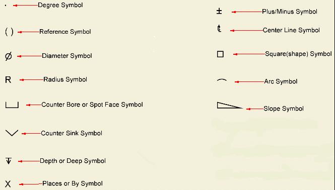
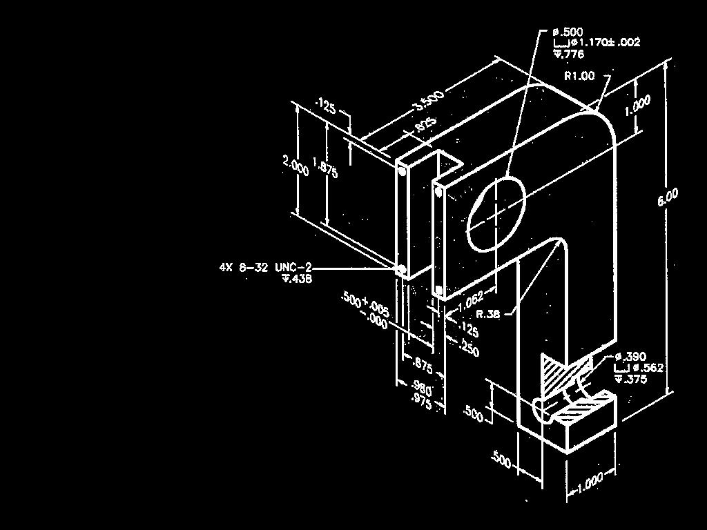
5 Dimensioning Symbols
6 Dimensioning Methods Dimensions are represented on a drawing using one of two systems, unidirectional or aligned. The unidirectional method means all dimensions are read in the same direction. The aligned method means the dimensions are read in alignment with the dimension lines or side of the part, some read horizontally and others read vertically.


7 Dimension Text Unidirectional vs. Aligned Unidirectional dimensions are placed so they can be read from the bottom of the drawing sheet. This method is commonly used in mechanical drafting. Aligned dimensions are placed so the horizontal dimensions can be read from the bottom of the drawing sheet and the vertical dimensions can be read from the right side of the drawing sheet. This method is commonly used in architectural and structural drafting.
8 Two Types of Dimensions There are two classifications of dimensions: size and location. Size dimensions are placed in direct relationship to a feature to identify the specific size. Location dimensions are used to identify the relationship of a feature to another feature within an object.

9 ANSI Drafting Standards - Dimensions Remember - a location dimension locates holes or other part features. A size dimension provides a radius, diameter, length, width, thickness, etc. Planchard Copyright 2012
10 Elementary Dimensioning Dimensions should be stacked with shorter dimensions closer to the object and longer dimensions farther away so that dimension lines will not cross extension lines. Extension lines crossing extension lines is OK
11 Elementary Dimensioning Extension lines should extend to the profile of the object with a small gap between the end of the extension line and the object. No line of the drawing should be used as a dimension line or coincide with a dimension line.
12 Elementary Dimensioning Dimensions at each stacking level should be aligned.
13 Elementary Dimensioning Don t break extension lines.
14 Elementary Dimensioning Dimensions shouldn t be placed on a view unless doing so is unavoidable or if it enhances clarity.
15 Elementary Dimensioning Dimensions should be placed in views where the dimensioned features are shown in their true shapes. Avoid dimensioning to hidden lines wherever possible.
16 Elementary Dimensioning In complicated drawings dimensions often have to be placed on the view. In this particular case, consider changing the scale of the drawing to accommodate the dimensions. Enough space should be provided to avoid crowding and misinterpretation.
17 ANSI Drafting Standards - Dimensions Placement of Linear Dimensions - Order of Preference. When there is not enough room on the drawing view between the extension lines to accommodate either the dimension value or the dimension lines - located the outside extension lines as illustrated. Planchard Copyright 2012
18 Dimensioning Checklist Each dimension should be written clearly with only one way to be interpreted. A feature should be dimensioned only once. Dimension and extension lines should not cross. Each feature should be dimensioned. Dimension features or surfaces should be done to a logical reference point.
19 Dimension Checklist Dimension a circle with a diameter and an arc with a radius. A center line should be extended and used as an extension line. Dimension features on a view should clearly show its true shape. Enough space should be provided to avoid crowding and misinterpretation.
20 Dimension Checklist Extension lines and object lines should not overlap. Dimensions should be placed outside the part. Center lines or marks should be used on all circles and holes.
21 Fillets and Rounds Fillets Rounds
22 Fillets and Rounds Large arcs use center marks. Use a capital R for dimensioning the arc. Small arcs do not need center marks. Arrow can be outside the arc.
23 Slot Dimensioning Two acceptable methods for dimensioning slotted holes.

24 Dimensioning Radial Patterns Angles and radius values are used to locate the centers of radial patterned features, such as the holes on this plate.

25 Dimension Guidelines
26 1. Dimensions should NOT be duplicated, or the same information given in two different ways. Incorrect
27 1. Dimensions should NOT be duplicated, or the same information given in two different ways.
28 2. No unnecessary dimensions should be used only those needed to produce or inspect the part. Incorrect
29 2. No unnecessary dimensions should be used only those needed to produce or inspect the part.
30 3. Dimensions should be attached to the view that best shows the contour of the feature to be dimensioned. Incorrect
31 3. Dimensions should be attached to the view that best shows the contour of the feature to be dimensioned.
32 4. Whenever possible, avoid dimensioning to hidden lines and features. Incorrect
33 4. Whenever possible, avoid dimensioning to hidden lines and features.
34 5. Avoid dimensioning over or through the object. Incorrect
35 5. Avoid dimensioning over or through the object.
36 6. A dimension should be attached to only one view; for example, extension lines should not connect two views. Incorrect
37 6. A dimension should be attached to only one view; for example, extension lines should not connect two views.
38 7. Whenever possible, locate dimensions between adjacent views. Incorrect
39 7. Whenever possible, locate dimensions between adjacent views.

40 8. Avoid crossing extension lines, but do not break them when they do cross. Multiple extension line crossings may be confused for the outside corner of the part.
41 9. Whenever possible, avoid sending extension lines through object views. Incorrect
42 9. Whenever possible, avoid sending extension lines through object views.
43 10. In general, a circle is dimensioned by its diameter and an arc by its radius.
44 11. Holes are located by their centerlines, which may be extended and used as extension lines.
45 12. Holes should be located and sized in the view that shows the feature as a circle. Incorrect
46 12. Holes should be located and sized in the view that shows the feature as a circle.
47 13. Do not cross a dimension line with an extension line, and avoid crossing dimensions with leader lines.
48 13. Do not cross a dimension line with an extension line, and avoid crossing dimensions with leader lines.
49 14. Leader lines point toward the center of the feature, and should not occur horizontally or vertically.

50 15. Dimension numbers should be centered between arrowheads, except when using stacked dimensions, and then the numbers should be staggered. Incorrect

51 15. Dimension numbers should be centered between arrowheads, except when using stacked dimensions, and then the numbers should be staggered.
52 16. Concentric circles are dimensioned in the longitudinal view, whenever practical. Incorrect
53 16. Concentric circles are dimensioned in the longitudinal view, whenever practical.

54 Tolerances
55 Variation is Unavoidable No two manufactured objects are identical in every way. Some degree of variation will exist. Engineers apply tolerances to part dimensions to reduce the amount of variation that occurs.
56 ANSI/ASME Standard ANSI/ASME Standard Y14.5 Each dimension shall have a tolerance, except those dimensions specifically identified as reference, maximum, minimum, or stock. The tolerance may be applied directly to the dimension or indicated by a general note located in the title block of the drawing.
57 Tolerances A tolerance is an acceptable amount of dimensional variation that will still allow an object to function correctly.
58 Tolerances A tolerance is an acceptable amount of dimensional variation that will still allow an object to function correctly.
59 Tolerances

60 Tolerances Three basic tolerances that occur most often on working drawings are: limit dimensions, unilateral, and bilateral tolerances.
61 Tolerances Three basic tolerances that occur most often on working drawings are: limit dimensions, unilateral, and bilateral tolerances.
62 Limit Dimensions Limit dimensions are two dimensional values stacked on top of each other. The dimensions show the largest and smallest values allowed. Anything in between these values is acceptable.
63 Limit Dimensions These are limit dimensions, because the upper and lower dimensional sizes are stacked on top of each other.
64 Unilateral Tolerance A unilateral tolerance exists when a target dimension is given along with a tolerance that allows variation to occur in only one direction.
65 Unilateral Tolerance This tolerance is unilateral, because the size may only deviate in one direction.
66 Bilateral Tolerance A bilateral tolerance exists if the variation from a target dimension is shown occurring in both the positive and negative directions.
67 General Tolerances If no tolerances are specified at the dimension level, then general tolerances may be applied by deliberately controlling the number of values past the decimal point on each dimension. Angles = ±.5 Linear Dimensions X.X = ±.020 X.XX = ±.010 X.XXX = ±.005


68 General Tolerances Tolerances X.X = ±.020 X.XX = ±.010 X.XXX = ±.005
69 Total Tolerance The total tolerance is a value that describes the maximum amount of variation. Tolerance =.010 Total Tolerance = Target Dimension
70 Total Tolerance A measuring device should be able to accurately measure within 1/10 th of the total blueprint tolerance identified Target Dimension
71 Tolerances and Measuring In this case, a measuring device should be able to take accurate measurements to within two thousandths of an inch. Total tolerance = = x x =.020 x =.002 X = the minimum accuracy of the measuring device
72 Three Types of Fit There are three types of fit that should be considered when working with tolerances. Clearance Fit- have limits of size so prescribed that a clearance always results when mating parts are assembled. Interference Fit- have limits of size so prescribed that an interference always results when mating parts are assembled. Transition Fit- have limits of size indicating that either a clearance or an interference may result when mating parts are assembled.
the same information given in two different 1. Dimensions should NOT be duplicated, or Dimension Guidelines Incorrect ways.
 Dimension Guidelines 1. Dimensions should NOT be duplicated, or the same information given in two different ways. Incorrect 1. Dimensions should NOT be duplicated, or the same information given in two
Standards for Your Career Field
 Dimensioning Dimensions Dimensions are used to describe the sizes and relationships between features in your drawing. Dimensions are used to manufacture parts and to inspect the resulting parts to determine
DIMENSIONING ENGINEERING DRAWINGS
 DIMENSIONING ENGINEERING DRAWINGS An engineering drawing must be properly dimensioned in order to convey the designer s intent to the end user. Dimensions provide the information needed to specify the
Student Name: Teacher: Date: District: Rowan. Assessment: 9_12 T and I IC61 - Drafting I Test 2. Description: Drafting 1 - Test 6.
 Student Name: Teacher: Date: District: Rowan Assessment: 9_12 T and I IC61 - Drafting I Test 2 Description: Drafting 1 - Test 6 Form: 501 1. 2X on a hole note means: A. Double the size of the hole. B.
1 st Subject: Types and Conventions of Dimensions and Notes
 Beginning Engineering Graphics 7 th Week Lecture Notes Instructor: Edward N. Locke Topic: Dimensions, Tolerances, Graphs and Charts 1 st Subject: Types and Conventions of Dimensions and Notes A. Definitions
3. The dimensioning SYMBOLS for arcs and circles should be given:
 Draft Student Name: Teacher: District: Date: Wake County Test: 9_12 T and I IC61 - Drafting I Test 2 Description: 4.08 Dimensioning Form: 501 1. The MINIMUM amount of space between two, ADJACENT DIMENSION
Geometric dimensioning & tolerancing (Part 1) KCEC 1101
 KCEC 1101") Geometric dimensioning & tolerancing (Part 1) KCEC 1101 Introduction Before an object can be built, complete information about both the size and shape of the object must be available. The exact shape of
Geometric dimensioning & tolerancing (Part 1) KCEC 1101 Introduction Before an object can be built, complete information about both the size and shape of the object must be available. The exact shape of
Dimensioning. Dimensions: Are required on detail drawings. Provide the shape, size and location description: ASME Dimensioning Standards
 Dimensioning Dimensions: Are required on detail drawings. Provide the shape, size and location description: - Size dimensions - Location dimensions - Notes Local notes (specific notes) General notes ASME
. These are not necessarily. There is much more to the, as we will see.
 Dimensioning Study Guide (Study Chapter 11 in Technical Drawing) 1. In addition to a complete shape description of an object... a drawing of the design must also give a complete ; that is, it must be.
DFTG-1305 Technical Drafting Prof. Francis Ha
 DFTG-1305 Technical Drafting Prof. Francis Ha Session 5 Dimensioning Geisecke s textbook: 14 th Ed. Chapter 10 p. 362 15 th Ed. Chapter 11 p. 502 Update: 17-0508 Dimensioning Part 1 of 2 Dimensioning Summary
ENGINEERING GRAPHICS ESSENTIALS. (A Text and Lecture Aid) Second Edition. Kirstie Plantenberg University of Detroit Mercy SDC PUBLICATIONS
 Second Edition. Kirstie Plantenberg University of Detroit Mercy SDC PUBLICATIONS") ENGINEERING GRAPHICS ESSENTIALS (A Text and Lecture Aid) Second Edition Kirstie Plantenberg University of Detroit Mercy SDC PUBLICATIONS Schroff Development Corporation www.schroff.com www.schroff-europe.com
ENGINEERING GRAPHICS ESSENTIALS (A Text and Lecture Aid) Second Edition Kirstie Plantenberg University of Detroit Mercy SDC PUBLICATIONS Schroff Development Corporation www.schroff.com www.schroff-europe.com
Activity 7.3 Tolerances
 Page 1 of 9 Activity 7.3 Tolerances Introduction The term variation describes the degree to which an object or idea differs from others of the same type or from a standard. Examples of variation are everywhere
Dimensioning in the figure below could be improved by: A
 1-Multiview-study Page 1 of 8 irections For Numbers 1-53 : Read each of the following multiple-choice items and the possible answers carefully. Mark the letter of the correct answer on your answer sheet
Chapter 2: Dimensioning Basic Topics Advanced Topics Exercises
 Chapter 2: Dimensioning Basic Topics Advanced Topics Exercises Dimensioning: Basic Topics Summary 2-1) Detailed Drawings 2-2) Learning to Dimension 2-3) Dimension Appearance and Techniques. 2-4) Dimensioning
UNIT Lines and Symbols
 3 UNIT Lines and Symbols Various lines on a drawing have different meanings. They may appear solid, broken, thick, or thin. Each is designed to help the blueprint reader make an interpretation. The standards
Geometric Dimensioning and Tolerancing
 Geometric Dimensioning and Tolerancing (Known as GDT) What is GDT Helps ensure interchangeability of parts. Use is dictated by function and relationship of the part feature. It does not take the place
CHAPTER 01 PRESENTATION OF TECHNICAL DRAWING. Prepared by: Sio Sreymean
 CHAPTER 01 PRESENTATION OF TECHNICAL DRAWING Prepared by: Sio Sreymean 2015-2016 Why do we need to study this subject? Effectiveness of Graphics Language 1. Try to write a description of this object. 2.
A Brief Introduction to Engineering Graphics. Will Durfee & Tim Kowalewski Department of Mechanical Engineering University of Minnesota
 A Brief Introduction to Engineering Graphics Will Durfee & Tim Kowalewski Department of Mechanical Engineering University of Minnesota Opening comments Engineering graphics is the method for documenting
Dimensioning the Rectangular Problem
 C h a p t e r 3 Dimensioning the Rectangular Problem In this chapter, you will learn the following to World Class standards: 1. Creating new layers in an AutoCAD drawing 2. Placing Centerlines on the drawing
Chapter 8. Technical Drawings
 Chapter 8 Technical Drawing Technical Drawings Multiview drawings Also called three-view drawings Simple objects take three views Front, top, one side Title block Identifies who did the design Gives date,
EN1740 Computer Aided Visualization and Design Spring /16/2012 Brian C. P. Burke
 EN1740 Computer Aided Visualization and Design Spring 2012 2/16/2012 Brian C. P. Burke Last Time: Measuring within Pro/E 2D representation Orthographic projection 3 rd Angle vs. 1 st Angle Creating engineering
Test Answers and Exam Booklet. Geometric Tolerancing
 Test Answers and Exam Booklet Geometric Tolerancing iii Contents ANSWERS TO THE GEOMETRIC TOLERANCING TEST............. 1 Part 1. Questions Part 2. Calculations SAMPLE ANSWERS TO THE GEOMETRIC TOLERANCING
Aircraft Drawing and Blueprint Reading
 Aircraft Drawing and Blueprint Reading Course Introduction Types of drawings Engineering also known as production or working drawings. Block diagram Types of Drawings Schematics Sketches Charts and graphs
Dimensioning the Bracket Problem
 C h a p t e r 11 Dimensioning the Bracket Problem In this chapter, you will learn the following to World Class standards: 1. Dimensioning a Multiple View Drawing 2. Placing Center Marks on a Multiple View
Engineering Working Drawings Basics
 Engineering Working Drawings Basics Engineering graphics is an effective way of communicating technical ideas and it is an essential tool in engineering design where most of the design process is graphically
AutoCAD Tutor 2011 Support Docs
 AutoCAD Tutor 2011 Support Docs CHAPTER 1 CUSTOMIZING THE QUICK ACCESS TOOLBAR One of the advantages of the Quick Access Toolbar is the ability to display the AutoCAD commands that you frequently use.
C H A P T E R E L E V E N
 DIMENSIONING C H A P T E R E L E V E N Giesecke, Hill, Spencer, Dygdon, Novak, Lockhart, Goodman 1 OBJECTIVES 1. Use conventional dimensioning techniques to describe size and shape accurately on an engineering
Dimension Styles. EDT Chapter 18 - Basic Dimensioning Practices 1
 Dimension Styles EDT 310 - Chapter 18 - Basic Dimensioning Practices 1 Dimension Styles The appearance of dimensions is controlled by over 70 different settings. Dimension Styles are saved configurations
Dimensioning 2-4) Dimensioning and Locating Simple Features
 Dimensioning and Locating Simple Features") Dimensioning 2-4) Dimensioning and Locating Simple Features Dimensioning Features a) A circle is dimensioned by its diameter and an arc by its radius using a leader line and a note. Exercise 2-6 Circular
Dimensioning 2-4) Dimensioning and Locating Simple Features Dimensioning Features a) A circle is dimensioned by its diameter and an arc by its radius using a leader line and a note. Exercise 2-6 Circular
Geometric Dimensioning and Tolerancing
 Geometric dimensioning and tolerancing (GDT) is Geometric Dimensioning and Tolerancing o a method of defining parts based on how they function, using standard ASME/ANSI symbols; o a system of specifying
Advanced Dimensional Management LLC
 Index: Mechanical Tolerance Stackup and Analysis Bryan R. Fischer Accuracy and precision 8-9 Advanced Dimensional Management 14, 21, 78, 118, 208, 251, 286, 329-366 Ambiguity 4, 8-14 ASME B89 48 ASME Y14.5M-1994
UNIT 5a STANDARD ORTHOGRAPHIC VIEW DRAWINGS
 UNIT 5a STANDARD ORTHOGRAPHIC VIEW DRAWINGS 5.1 Introduction Orthographic views are 2D images of a 3D object obtained by viewing it from different orthogonal directions. Six principal views are possible
Shaft Hanger - SolidWorks
 ME-430 INTRODUCTION TO COMPUTER AIDED DESIGN Shaft Hanger - SolidWorks BY: DR. HERLI SURJANHATA ASSIGNMENT Submit TWO isometric views of the Shaft Hanger with your report, 1. Shaded view of the trimetric
Assembly Receiver/Hitch/Ball/Pin to use for CAD LAB 5A and 5B:
 MECH 130 CAD LAB 5 SPRING 2017 due Friday, April 21, 2016 at 4:30 PM All of LAB 5 s hardcopies will be working drawing layouts. Do not print out from the part file. We will be using the ME130DRAW drawing
METRIC FASTENERS 1520 METRIC FASTENERS
 1520 METRIC FASTENERS METRIC FASTENERS A number of American National Standards covering metric bolts, screws, nuts, and washers have been established in cooperation with the Department of Defense in such
Geometric Tolerances & Dimensioning
 Geometric Tolerances & Dimensioning MANUFACTURING PROCESSES - 2, IE-352 Ahmed M. El-Sherbeeny, PhD KING SAUD UNIVERSITY Spring - 2015 1 Content Overview Form tolerances Orientation tolerances Location
Beginner s Guide to SolidWorks Alejandro Reyes, MSME Certified SolidWorks Professional and Instructor SDC PUBLICATIONS
 Beginner s Guide to SolidWorks 2008 Alejandro Reyes, MSME Certified SolidWorks Professional and Instructor SDC PUBLICATIONS Schroff Development Corporation www.schroff.com www.schroff-europe.com Part Modeling
Multiview Projection
 DFTG-1305 Technical Drafting Prof. Francis Ha Session 4 Multiview Projection (or Orthographic Projection) Reading: Geisecke s textbook: 14 th Ed. Chapter 5 p.162 15 th Ed. Chapter 6 p.232 Update: 17-0510
Creo: Hole, Fillet, and Round Layout/Dimension Tutorial. By: Matthew Jourden Brighton High School
 Creo: Hole, Fillet, and Round Layout/Dimension Tutorial Layout of a Part with Holes 1. Open a blank drawing with your border and title block By: Matthew Jourden Brighton High School 2. Place the front,
MGC 110. Dimensioning. Afr: Maatskrywing
 MGC 110 Dimensioning Afr: Maatskrywing Accuracy (correct values) Clearness (placed at appropriate positions) Completeness (fully defined, but no duplications) Readability (correct line quality) Afr: Akkuraatheid
2001 Academic Challenge
 Worldwide Youth in Science and Engineering 2001 Academic Challenge ENGINEERING GRAPHICS TEST - STATE FINALS GENERAL DIRECTIONS Engineering Graphics Test Production Team Ralph Dirksen, Western Illinois
DRAFTING MANUAL. Dimensioning and Tolerancing Rules
 Page 1 1.0 General This section is in accordance with ASME Y14.5-2009 Dimensioning and Tolerancing. Note that Rule #1 is the only rule that is numbered in the 2009 standard. All of the other rules fall
Solid Part Four A Bracket Made by Mirroring
 C h a p t e r 5 Solid Part Four A Bracket Made by Mirroring This chapter will cover the following to World Class standards: Sketch of a Solid Problem Draw a Series of Lines Finish the 2D Sketch Extrude
Engineering drawing. Semester I/II Mechanical Engineering Department Technical University of Gdańsk. Lecture 8
 Engineering drawing Semester I/II Mechanical Engineering Department Technical University of Gdańsk Lecture 8 Representing Tolerance Values Tolerance is the total amount a dimension may vary and is the
An Introduction to Dimensioning Dimension Elements-
 An Introduction to Dimensioning A precise drawing plotted to scale often does not convey enough information for builders to construct your design. Usually you add annotation showing object measurements
DFTG-1305 Technical Drafting Prof. Francis Ha
 DFTG-1305 Technical Drafting Prof. Francis Ha Session 4 Orthographic Projection (or Multiview Projection) Reading: Geisecke s textbook: 14 th Ed. Chapter 5 p.162 15 th Ed. Chapter 6 p.232 Update: 18-0205
PORTAGE COUNTY WATER RESOURCES DRAFTING STANDARDS. Date: January 26, 2001
 PORTAGE COUNTY WATER RESOURCES DRAFTING STANDARDS Date: January 26, 2001 Portage County Water Resources Drafting Standards. AutoCad 2000/Land Development Desktop R2 Friday, January 26, 2001 Preface: Part
Dimensioning: There are a few simple best practices which can help us dimension a working drawing:
 Dimensioning and Tolerancing Prepared by: Michael Hypes Cornell University Preparation: One of the most common problems for new designers is choosing dimension that do not reflect the purpose of the part.
Introduction. Objectives
 Introduction As more and more manufacturers become immersed in the global economy, standardization plays a critical role in their success. Geometric dimensioning and tolerancing (GD&T) provides a set of
ME 114 Engineering Drawing II
 ME 114 Engineering Drawing II FITS, TOLERANCES and SURFACE QUALITY MARKS Mechanical Engineering University of Gaziantep Dr. A. Tolga Bozdana Assistant Professor Tolerancing Tolerances are used to control
Interpretation of Drawings. An Introduction to the Basic Concepts of Creating Technical Drawings
 Interpretation of Drawings An Introduction to the Basic Concepts of Creating Technical Drawings Introduction In the design process drawings are the main way in which information about an object or product
Activity 7.1 More Dimensioning
 Activity 7.1 More Dimensioning Introduction The basic standard dimensioning method established by the American National Standards Institute and the American Society of Mechanical Engineers (ANSI or ASME)
Copyrighted Material. Copyrighted Material. Copyrighted. Copyrighted. Material
 Engineering Graphics ORTHOGRAPHIC PROJECTION People who work with drawings develop the ability to look at lines on paper or on a computer screen and "see" the shapes of the objects the lines represent.
Making an Architectural Drawing Template
 C h a p t e r 8 Addendum: Architectural Making an Architectural Drawing Template In this chapter, you will learn the following to World Class standards:! Starting from Scratch for the Last time! Creating
2012 Academic Challenge
 2012 Academic Challenge ENGINEERING GRAPHICS TEST SECTIONAL This Test Consists of 40 Questions Engineering Graphics Test Production Team Ryan Brown, Illinois State University Author/Team Leader Jacob Borgerson,
LAB 1A: Intro to SolidWorks: 2D -> 3D Brackets
 LAB 1A: Intro to SolidWorks: 2D -> 3D Brackets Set units Create Sketch Add relations Linear patterns Mirror Fillet Extrude Extrude cut First, set units. click Option on top of main menu Open Document Properties
DWG 002. Blueprint Reading. Geometric Terminology Orthographic Projection. Instructor Guide
 DWG 002 Blueprint Reading Geometric Terminology Orthographic Projection Instructor Guide Introduction Module Purpose The purpose of the Blueprint Reading modules is to introduce students to production
Starting a 3D Modeling Part File
 1 How to Create a 3D Model and Corresponding 2D Drawing with Dimensions, GDT (Geometric Dimensioning and Tolerance) Symbols and Title Block in SolidWorks 2013-2014 By Edward Locke This tutorial will introduce
Technical Drawing 101 with AutoCAD 2018
 Technical Drawing 101 with AutoCAD 2018 A Multidisciplinary Guide to Drafting Theory and Practice with Video Instruction Douglas Smith Antonio Ramirez Ashleigh Fuller SDC PUBLICATIONS Better Textbooks.
Basic Welding Symbols and Their Location Significance
 Basic Welding Symbols and Their Location Significance Objectives After completing this chapter, the student should be able to: Understand the basics of welding symbols List the major parts of a welding
Geometric Boundaries II
 Geometric Boundaries II Interpretation and Application of Geometric Dimensioning and Tolerancing (Using the Inch and Metric Units) Based on ASME Y14.5-2009 (R2004) Written and Illustrated by Kelly L. Bramble
Project Booklet. Structural Drafting with AutoCAD
 Project Booklet Structural Drafting with AutoCAD Introduction 1 General Setup 2 Border and Title Block 3 Drafting the Foundation Plan (Plate 1) 8 Drafting the South Elevation (Plate 2) 11 Drafting Section
COMMON SYMBOLS/ ISO SYMBOL ASME Y14.5M ISO FEATURE CONTROL FRAME DIAMETER/ SPHERICAL DIAMETER/ AT MAXIMUM MATERIAL CONDITION
 1 82 COMMON SYMBOLS/ Shown below are the most common symbols that are used with geometric tolerancing and other related dimensional requirements on engineering drawings. Note the comparison with the ISO
Foreword. If you have any questions about these tutorials, drop your mail to
 Foreword The main objective of these tutorials is to give you a kick start using Solidworks. The approach to write this tutorial is based on what is the most important knowledge you should know and what
Contents. Notes on the use of this publication
 Contents Preface xxiii Scope Notes on the use of this publication xxv xxvi 1 Layout of drawings 1 1.1 General 1 1.2 Drawing sheets 1 1.3 Title block 2 1.4 Borders and frames 2 1.5 Drawing formats 2 1.6
Scale and Dimensioning (Architectural Board Drafting)
") Youth Explore Trades Skills Description In this activity, the teacher will first select an object that is larger than the page and scale it to fit in the designated drawing area to explain architectural
Youth Explore Trades Skills Description In this activity, the teacher will first select an object that is larger than the page and scale it to fit in the designated drawing area to explain architectural
Flip for User Guide. Inches. When Reliability Matters
 Flip for User Guide Inches by When Reliability Matters Mastercam HSM Performance Pack Tutorial 1 Mastercam HSM Performance Pack Tutorial Tutorial I... 2 Getting started... 2 Tools used... 2 Roughing...
DUE DATE: Friday 4/6/2018 at 3:30 PM
 MECH 130 SPRING 2018 CAD LAB 4 FINAL REVISION HARDCOPIES NEEDED DUE DATE: Friday 4/6/2018 at 3:30 PM After the revised hitch, the ball and the pin parts were created from the Handout call LAB4 PART Creation,
Engineering & Computer Graphics Workbook Using SolidWorks 2014
 Engineering & Computer Graphics Workbook Using SolidWorks 2014 Ronald E. Barr Thomas J. Krueger Davor Juricic SDC PUBLICATIONS Better Textbooks. Lower Prices. www.sdcpublications.com Powered by TCPDF (www.tcpdf.org)
Tolerancing. Summary
 Tolerancing Summary Summary What will we learn We will learn about tolerancing and how important this technique is to mass production. Key points If a feature s size is toleranced, it is allowed to vary
CAD and Drafting Standards Working Drawings
 CAD and Drafting Standards Working Drawings Gregory Mocko Introduction 2 The purpose of drawing or generating a CAD document is to communicate Essentially, since communication is the goal, some standards
Study Unit. Auxiliary Views. This sneak preview of your study material has been prepared in advance of the book's actual online release.
 Study Unit Auxiliary Views This sneak preview of your study material has been prepared in advance of the book's actual online release. iii Preview You re entering now into another subject area in your
ME Week 2 Project 2 Flange Manifold Part
 1 Project 2 - Flange Manifold Part 1.1 Instructions This project focuses on additional sketching methods and sketching commands. Revolve and Work features are also introduced. The part being modeled is
Engineering & Computer Graphics Workbook Using SOLIDWORKS
 Engineering & Computer Graphics Workbook Using SOLIDWORKS 2017 Ronald E. Barr Thomas J. Krueger Davor Juricic SDC PUBLICATIONS Better Textbooks. Lower Prices. www.sdcpublications.com Powered by TCPDF (www.tcpdf.org)
Assignment 12 CAD Mechanical Part 2
 Assignment 12 CAD Mechanical Part 2 Objectives In this assignment you will learn to apply the hidden lines, isometric snap, and ellipses commands along with commands previously learned.. General Hidden
This section will take you through the process of drawing a fixture base. Your entire part, in all views, should look like Figure 1.
 Fixture Base Preface This section will take you through the process of drawing a fixture base. Your entire part, in all views, should look like Figure 1. Figure 1 92 / Scripted 3D Drawings: Fixture Base
SolidWorks Part I - Basic Tools SDC. Includes. Parts, Assemblies and Drawings. Paul Tran CSWE, CSWI
 SolidWorks 2015 Part I - Basic Tools Includes CSWA Preparation Material Parts, Assemblies and Drawings Paul Tran CSWE, CSWI SDC PUBLICATIONS Better Textbooks. Lower Prices. www.sdcpublications.com Powered
Isometric Drawings. Figure A 1
 A Isometric Drawings ISOMETRIC BASICS Isometric drawings are a means of drawing an object in picture form for better clarifying the object s appearance. These types of drawings resemble a picture of an
Orthographic Projection
 Orthographic Projection Why Orthographic Projection is used in technical drawing Orthographic projection is a method of producing a number of separate two-dimensional inter-related views, which are mutually
TECHNICAL DESIGN II (546)
") DESCRIPTION The second in a sequence of courses that prepares individuals with an emphasis in developing technical knowledge and skills to develop working drawings in support of mechanical and industrial
DESCRIPTION The second in a sequence of courses that prepares individuals with an emphasis in developing technical knowledge and skills to develop working drawings in support of mechanical and industrial
SOLIDWORKS 2015 and Engineering Graphics
 SOLIDWORKS 2015 and Engineering Graphics An Integrated Approach Randy H. Shih SDC PUBLICATIONS Better Textbooks. Lower Prices. www.sdcpublications.com Powered by TCPDF (www.tcpdf.org) Visit the following
Introduction. In engineering you are usually concerned with a number of parts or components fitting together to make an: assembly
 Limits and Fits Introduction In engineering you are usually concerned with a number of parts or components fitting together to make an: assembly To assemble components together engineers must control the
A Concise Introduction to Engineering Graphics
 A Concise Introduction to Engineering Graphics Fourth Edition Including Worksheet Series A Timothy J. Sexton, Professor Department of Industrial Technology Ohio University BONUS Book on CD: TECHNICAL GRAPHICS
2018 Technical Drawing Specifications Resource A guide to support VCE Visual Communication Design Study Design
 2018 Technical Drawing Specifications Resource A guide to support VCE Visual Communication Design Study Design 2018 22 VICTORIAN CURRICULUM AND ASSESSMENT AUTHORITY 1 Contents A guide to support VCE Visual
Part 8: The Front Cover
 Part 8: The Front Cover 4 Earpiece cuts and housing Lens cut and housing Microphone cut and housing The front cover is similar to the back cover in that it is a shelled protrusion with screw posts extruding
Standards and Competencies
 Skill Performance The skill performance assessment includes the completion of a metal project and a demonstration of the ability to weld carbon steel, aluminum or stainless-steel project in various using
Lesson 6 2D Sketch Panel Tools
 Lesson 6 2D Sketch Panel Tools Inventor s Sketch Tool Bar contains tools for creating the basic geometry to create features and parts. On the surface, the Geometry tools look fairly standard: line, circle,
Test Code: 8294 / Version 1
 Pennsylvania Customized Assessment Blueprint Test Code: 8294 / Version 1 Copyright 2014. All Rights Reserved. General Assessment Information Blueprint Contents General Assessment Information Written Assessment
for Solidworks TRAINING GUIDE LESSON-9-CAD
 for Solidworks TRAINING GUIDE LESSON-9-CAD Mastercam for SolidWorks Training Guide Objectives You will create the geometry for SolidWorks-Lesson-9 using SolidWorks 3D CAD software. You will be working
Geometric Boundaries
 Geometric Boundaries Interpretation and Application of Geometric Dimensioning and Tolerancing (Using the Customary Inch System) Based on ASME Y14.5M-1994 Written and Illustrated by Kelly L. Bramble Published
Trade of Metal Fabrication. Module 3: Plate Fabrication Unit 12: Duct Sections Phase 2
 Trade of Metal Fabrication Module 3: Plate Fabrication Unit 12: Duct Sections Phase 2 Table of Contents List of Figures... 4 List of Tables... 5 Document Release History... 6 Module 3 Plate Fabrication...
Top Down Assembly Modeling Release Wildfire 2.0
 Top Down Assembly Modeling Release Wildfire 2.0 Note: Comprehensive Modeling Assignment This is a 30 point assignment as such takes the place of the final exam. Four Plate Mold Base, Inner Two Plates Begin
Engineering Design with SolidWorks A Step-by-Step Project Based Approach Utilizing 3D Solid Modeling. David C. Planchard & Marie P.
 Engineering Design with SolidWorks 2003 A Step-by-Step Project Based Approach Utilizing 3D Solid Modeling David C. Planchard & Marie P. Planchard SDC PUBLICATIONS www.schroff.com www.schroff-europe.com
Engineering Graphics Essentials with AutoCAD 2015 Instruction
 Kirstie Plantenberg Engineering Graphics Essentials with AutoCAD 2015 Instruction Text and Video Instruction Multimedia Disc SDC P U B L I C AT I O N S Better Textbooks. Lower Prices. www.sdcpublications.com
Dimensioning part 1 with SolidWorks. ENGR 1182 SolidWorks 08
 Dimensioning part 1 with SolidWorks ENGR 1182 SolidWorks 08 Today s Objectives Formal Drawing Components: Dimensioning with SolidWorks SW08 Activity SW08 Application Formal Drawings Definition: Detailed
SDC. SolidWorks Tutorial 2001Plus. A Competency Project Based Approach Utilizing 3D Solid Modeling. David C. Planchard & Marie P.
 2001Plus A Competency Project Based Approach Utilizing 3D Solid Modeling David C. Planchard & Marie P. Planchard SDC PUBLICATIONS www.schroff.com www.schroff-europe.com Project 2 Below are the desired
2003 Academic Challenge
 Worldwide Youth in Science and Engineering 2003 Academic Challenge ENGINEERING GRAPHICS TEST - SECTIONAL Engineering Graphics Test Production Team Ryan Brown, Illinois State University Author/Team Coordinator
ENGINEERING GRAPHICS ESSENTIALS
 ENGINEERING GRAPHICS ESSENTIALS with AutoCAD 2012 Instruction Introduction to AutoCAD Engineering Graphics Principles Hand Sketching Text and Independent Learning CD Independent Learning CD: A Comprehensive
GUIDELINES FOR DRAFTING
 UNIT 1 GUIDELINES FOR DRAFTING 1.1 Introduction The term draughting is used to describe the language of drafting in this book. It defines the terminology, symbology, conventions, and standards used in