: Fits and Tolerances
|
|
|
- Andrea Singleton
- 6 years ago
- Views:
Transcription
1 Fits and Tolerances CONTENTS

2 Why tolerances and fits are required? Due to the inevitable inaccuracy of manufacturing methods, a part cannot be made precisely to a given dimension, the difference between maximum and minimum limits of size of a part is the tolerance. Tolerance is the total amount that a specific dimension is permitted to vary. There is no such thing as an "exact size". Tolerance is key to interchangeable parts. When two parts are to be assembled, the relation resulting from the difference between their sizes before assembly is called a fit.

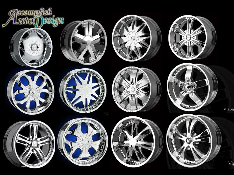
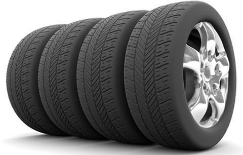
3 Examples of Interchangeable Manufacture Bottle caps Rims Tires
4 Advantages For Interchangeable Manufacture Replacement: One such part can freely replace another, without any custom fitting (such as filling). Easy to Assembly: This interchangeability allows easy assembly of new devices Repairing: Easier repair of existing devices. Minimizing time and cost: Minimizing both the time and skill required of the person doing the assembly or repair. Rapid Manufacturing: Machine tool enables the components to be manufactured more rapidly
5 How to decide tolerance? Functional requirements of mating parts Cost of production Available manufacturing process Choose as coarse tolerance as possible without compromising functional requirements. Proper balance between cost and quality of parts.
6 1.1 Dimensional Tolerances Some of the dimensional tolerances terms are defined as following: 1. Dimension 2. Size (It is a number expressed in a particular unit in the measurement of length) 3. Actual size (of a part) (the measured size of the finished part after machining) 4. Basic size (the theoretical size used as a starting point for the application of tolerances)
7 5. Design size (The ideal size for each component (shaft and hole) based upon a selected fit) 6. Limits of size (the maximum and minimum sizes shown by the tolerance dimension) 7. Maximum limit of size (Is the maximum size permitted for the part) 8. Minimum limit of size (it is the minimum size permitted for the part limit of size) 9. Maximum material limit (is the condition of a part when it contains the most amount of material. The MMC of an external feature (such as a shaft) is the upper limit. The MMC of an internal feature(such as a hole) is the lower limit) 10. Minimum material limit (is the condition of a part when it contains the least amount of material possible. The LMC of an external feature is the lower limit of the part. The LMC of an internal feature is the upper limit of the part.) 11. Tolerance (Tolerance is the difference between maximum limit of size and minimum limit of size)
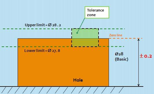
8 12. Zero line (it represents the basic size) 13. Upper deviation (It is the algebraic difference between minimum limit of size and its corresponding basic size) 14. Lower deviation (It is the algebraic difference between minimum limit of size and its corresponding basic size) 15. Tolerance zone (a region representing the difference between the upper and the lower limits) 16. Unilateral tolerance (In this method of presenting the limits, variation is allowed only on one side of the zero line) 17. Bilateral tolerance (Here the limits variation is allowed on either sides of the zero line) 18. Shaft (it refers to any external feature of a part, including any non cylindrical features as well) 19. Hole (the term used for any internal feature of a part including any non cylindrical as well)
9
10 The Tolerance is for the Hole as well as for the Shaft
11

12 Unilateral tolerance Bilateral tolerance Zero line
13
14 Calculate the maximum and minimum possible dimension for A
15 20. Basic shaft (the shaft chosen as a basis for the shaft basis system of fit) 21. Basic hole (the hole chosen as a basis for the hole basis system of fit) 22. Fit (Fit is the relationship that exists between two mating parts, a hole and shaft with respect to their dimensional difference ) 23. Basic size of a fit (common value of the basic size of the two parts of a fit)


16 24. Clearance fit Clearance fit Hole Shaft 25. Interference fit Tolerance Zone of Hole Tolerance Zone of Shaft 26. Transition fit Hole Shaft


17 27. Minimum clearance 28. Maximum clearance 29. Minimum interference

18 30. Maximum interference 31. Shaft-basis system of fits 32. Hole-basis system of fits Figure 1.3: Basic hole and shaft system

19 31 - Basic Shaft System of fits In this system the size of the shaft remains the same and the hole size is varied to get the required fit. Maximum shaft size is taken as the basic size, an allowance is assigned, and tolerances are applied on both sides of and away from this allowance.
20 32 - Basic Hole System of fits In this system the size of the hole remains the same and shaft size is varied to get the required fit. Minimum hole is taken as the basic size, an allowance is assigned, and tolerances are applied on both sides of and away from this allowance.
21 Or Zero deviation line


22
23 Some definitions Basic Size: is the size from which limits or deviations are assigned. Basic sizes, usually diameters, should be selected from a table of preferred sizes. Deviation: is the difference between the basic size and the hole or shaft size. Upper Deviation: is the difference between the basic size and the permitted maximum size of the part. Lower Deviation: is the difference between the basic size and the minimum permitted size of the part.
24 Some Definitions Fundamental Deviation: is the deviation closest to the basic size. This is identical to the upper deviation for shafts and the lower deviation for holes in a clearance fit. Tolerance: is the difference between the permitted minimum and maximum sizes of a part.
25 Some Definitions The hole-basis system of preferred fits is a system in which the basic diameter is the minimum size of the hole. For the generally preferred hole-basis system, the fundamental deviation is specified by the upper-case letter. The shaft-basis system of preferred fits is a system in which the basic diameter is the maximum size of the shaft. The fundamental deviation is given by the lowercase letter.
26 Some Definitions An interference fit results in an interference between two mating parts under all tolerance conditions. A clearance fit results in a clearance between the two mating parts under all tolerance conditions. A transition fit results in either a clearance or an interference condition between two assembled parts.
27
28 1.2 Symbols for Tolerances and Deviation and Symbols for Fits: 1. Tolerance values (The tolerance value is a function of the basic size and is indicated by a number called the grade. ) 2. Tolerance zone position The position of the tolerance zone with respect to the zero line, is indicated by a letter symbol, a capital letter for holes and a small letter The tolerance size thus defined by its basic value followed by a symbol composed of a letter and a number. It is established by a combination of the fundamental deviation indicated by a letter and the IT grade number. In the dimension 50H8, the H8 specifies the tolerance zone. International Tolerance Grade (IT) CHAPTER ONE Example for shaft: 45 g7
29 1.2 Symbols for Tolerances and Deviation and Symbols for Fits: 3.A fit (A fit is indicated by the basic size common to both components, followed by symbol corresponding to each component, the hole being quoted first) Example: 45 H8 g7 Possibly 45 H8 g7 Or 45 H8/g7 M0zNqbP&sig=ofRGWezbxKzJe9uW9zwxVZRZPdk&hl=en&sa=X&redir_esc=y#v=onepage&q=fundamental%20deviation%20selection%20fits%20IT&f=false
30 1.3: Grades of tolerances: Eighteen grades of tolerances are provided IT01, IT0 and IT1 to IT16 The Table 1.1 gives the possible degrees of precision or grade of tolerance, achieved with different machine tools.
31 Table 1.1: degree of precision or grade of tolerance Tolerance grade Intended for Applicable to components or machines I T 01 I T 0 I T 1 I T 2 Gauges Slip blocks, Reference gauges I T 3 I T 4 High quality gauges I T 5 I T 6 I T 7 I T 8 I T 9 I T 10 I T 11 I T 12 I T 13 I T 14 I T 15 I T 16 Fits Not for fits Ball bearing Grinding, Honing Broaching Center lathe turning Worn automatic lathe Milling Drilling, Rough turning Light press work Press work Die casting Stamping Sand casting
")
32 Representation of Tolerance 2) Number or Grade IT01, IT0, IT1,.IT16 CHAPTER ONE International Tolerance Grade Selection Tolerance Grade defines range of dimensions (dimensional variation) There are manufacturing constraints on tolerance grade chosen

33
34 Example
35 Metric Preferred Hole Based System of fit
36 Metric Preferred shaft Based System of fit
37 Holes Shafts Figure 1.5: Position of the various tolerance zones for a given diameter in the ISO system
38

39 Table for fundamental deviations for shafts

40 Table for fundamental deviations for shafts

41 Table for fundamental deviations for holes

42 Table for fundamental deviations for holes
43 1.4 Fundamental tolerance unit: CHAPTER ONE 1.4.1Values of standard tolerances: T = (G 1) ( D D) G = Tolerance grade IT6 IT Fundamental deviations: Shaft deviation: For each letter symbol defining the position of the tolerance zone, the magnitude and sign of one of the two deviations which is known as the fundamental deviations (upper deviation) es or lower deviation ei The other deviation is derived from the first one using the magnitude of the standard tolerance IT, by means of the following algebraic relationship: The fundamental deviation given by the formulae in above tables of deviations is, in principle, that corresponding to that limit closest to the zero line, in other words, the upper deviation es for shafts (a) to (h), and the lower deviation ei for shafts (j) to (Zc). ei = es - IT es = ei + IT
44 Hole deviation: For each letter symbol, defining the position of the tolerance zone, the magnitude and sign of the fundamental deviation (lower deviation EI for holes (A) to (H) and upper deviation ES for holes (J) to (Zc), The other deviation is derived from the first one, using the magnitude of the tolerance IT by means of the following relationships. ES = EI + IT OR EI = ES - IT
45 Example Determine which type of fit is presented by H7/p6? For basic size of 30 mm determine the dimensions of the hole and the shaft for the given fit. (Fit: 30 H7/p6) Capital H means basic hole system and upper deviation = zero H7 : Tol Grade 7 mean 21μ variation p6 : Tol Grade 6 means 13μ variation (p means upper deviation is 22 μ) INTERFERENCE FIT Φ Φ Φ Φ Fit: 40 H8/e6
46 Figure 1.7: Two comparable fits, with basic hole and basic shaft, in which a hole of a given grade is associated with a shaft with next finer grade (H7/P6 and P7/h6), have exactly the same clearance or interference.
IPE 381 Chapter:04 Limit, Fits and Tolerance
 IPE 381 Chapter:04 Limit, Fits and Tolerance Abdullah-Al-Mamun Lecturer, Dept. of IPE Outline Basics of Limit and Fit Interchangeable manufacturing Different types of fit Tolerance Tolerance Calculation
Session 10 Dimensions, Fits and Tolerances for Assembly
 Session 10 Dimensions, Fits and Tolerances for Assembly Lecture delivered by Prof. M. N. Sudhindra Kumar Professor MSRSAS-Bangalore 1 Variations in Production It is necessary that the dimensions, shape
SYSTEM OF LIMITS, FITS, TOLERANCES AND GAUGING
 UNIT 2 SYSTEM OF LIMITS, FITS, TOLERANCES AND GAUGING Introduction Definition of limits Need for limit system Tolerance Tolerance dimensions ( system of writing tolerance) Relationship between Tolerance
Engineering drawing. Semester I/II Mechanical Engineering Department Technical University of Gdańsk. Lecture 8
 Engineering drawing Semester I/II Mechanical Engineering Department Technical University of Gdańsk Lecture 8 Representing Tolerance Values Tolerance is the total amount a dimension may vary and is the
Module 1 Fundamentals of machine design. Version 2 ME, IIT Kharagpur
 Module 1 Fundamentals of machine design Lesson 3 Brief overview of design and manufacturing Instructional Objectives: At the end of this lesson, the students should be able to understand: Concept of limits
Assembly of Machine Parts
 Machine Drawing Assembly of Machine Parts Temporary Permanent Fastening Keying Fitting Welding Riveting Interference fit Machine drawing is the indispensable communicating medium employed in industries,
Fits and Tolerances. Prof Ahmed Kovacevic
 ME 1110 Engineering Practice 1 Engineering Drawing and Design - Lecture 7 Fits and Tolerances Prof Ahmed Kovacevic School of Engineering and Mathematical Sciences Room C130, Phone: 8780, E-Mail: a.kovacevic@city.ac.uk
ME 114 Engineering Drawing II
 ME 114 Engineering Drawing II FITS, TOLERANCES and SURFACE QUALITY MARKS Mechanical Engineering University of Gaziantep Dr. A. Tolga Bozdana Assistant Professor Tolerancing Tolerances are used to control
Tolerancing. Summary
 Tolerancing Summary Summary What will we learn We will learn about tolerancing and how important this technique is to mass production. Key points If a feature s size is toleranced, it is allowed to vary
Drawing & Design. Lecture 3. Lecturer: Dr. John Cheung
 MECH 313 Engineering Drawing & Design Lecture 3 Lecturer: Dr. John Cheung Outline Limits and tolerances Fits and allowances Surface texture Why ygive Tolerance? Manufacturing Practice is 6000 years old,
Introduction. In engineering you are usually concerned with a number of parts or components fitting together to make an: assembly
 Limits and Fits Introduction In engineering you are usually concerned with a number of parts or components fitting together to make an: assembly To assemble components together engineers must control the
ISO INTERNATIONAL STANDARD
 INTERNATIONAL STANDARD ISO 286-1 Second edition 2010-04-15 Geometrical product specifications (GPS) ISO code system for tolerances on linear sizes Part 1: Basis of tolerances, deviations and fits Spécification
GEOMETRICAL TOLERANCING
 GEOMETRICAL TOLERANCING Introduction In a typical engineering design and production environment, the designer of a part rarely follows the design to the shop floor, and consequently the only means of communication
AC : CALCULATION OF TOLERANCE STACKS USING DIRECT-POSITION APPROACH IN GEOMETRIC DIMENSIONING AND TOLERANCING
 AC 2009-138: CALCULATION OF TOLERANCE STACKS USING DIRECT-POSITION APPROACH IN GEOMETRIC DIMENSIONING AND TOLERANCING Cheng Lin, Old Dominion University American Society for Engineering Education, 2009
Test Answers and Exam Booklet. Geometric Tolerancing
 Test Answers and Exam Booklet Geometric Tolerancing iii Contents ANSWERS TO THE GEOMETRIC TOLERANCING TEST............. 1 Part 1. Questions Part 2. Calculations SAMPLE ANSWERS TO THE GEOMETRIC TOLERANCING
Tolerancing Fixed Fasteners 1
 + 856 SALT LAKE COURT SAN JOSE, CA 951 (408) 251 529 Tolerancing Fixed Fasteners 1.274- Figure 8-5 Fixed fastener The fixed fastener in Fig. 8-5 is fixed by one or more of the members being fastened. The
Geometric Tolerances & Dimensioning
 Geometric Tolerances & Dimensioning MANUFACTURING PROCESSES - 2, IE-352 Ahmed M. El-Sherbeeny, PhD KING SAUD UNIVERSITY Spring - 2015 1 Content Overview Form tolerances Orientation tolerances Location
the same information given in two different 1. Dimensions should NOT be duplicated, or Dimension Guidelines Incorrect ways.
 Dimension Guidelines 1. Dimensions should NOT be duplicated, or the same information given in two different ways. Incorrect 1. Dimensions should NOT be duplicated, or the same information given in two
Activity 7.3 Tolerances
 Page 1 of 9 Activity 7.3 Tolerances Introduction The term variation describes the degree to which an object or idea differs from others of the same type or from a standard. Examples of variation are everywhere
Metrology and instrumentation Indian Institute of Technology
 Metrology and instrumentation Indian Institute of Technology SOURCE: S. KALPAKJIAN BOOK SLIDE-WAY CROSS-SECTION Cross-section of a machine tool slide-way. The width, depth, angles, and other dimensions
Geometric Dimensioning and Tolerancing
 Geometric Dimensioning and Tolerancing (Known as GDT) What is GDT Helps ensure interchangeability of parts. Use is dictated by function and relationship of the part feature. It does not take the place
Rebuilding Worn 9N/2N Shift Covers by John Korschot - (March 2010)
") Rebuilding Worn 9N/2N Shift Covers by John Korschot - www.johnsoldiron.com (March 2010) If you have a 9N, chances are that your shift cover looks like this. This particular shift cover is an aluminum one
Rebuilding Worn 9N/2N Shift Covers by John Korschot - www.johnsoldiron.com (March 2010) If you have a 9N, chances are that your shift cover looks like this. This particular shift cover is an aluminum one
Representation of features Geometric tolerances. Prof Ahmed Kovacevic
 ME 1110 Engineering Practice 1 Engineering Drawing and Design - Lecture 6 Representation of features Geometric tolerances Prof Ahmed Kovacevic School of Engineering and Mathematical Sciences Room C130,
TECHNICAL DESIGN II (546)
") DESCRIPTION The second in a sequence of courses that prepares individuals with an emphasis in developing technical knowledge and skills to develop working drawings in support of mechanical and industrial
DESCRIPTION The second in a sequence of courses that prepares individuals with an emphasis in developing technical knowledge and skills to develop working drawings in support of mechanical and industrial
Inspection and Measurement
 Inspection and Measurement Inspection An action to insure what is being manufactured conforms to the specifications by attributes use of gages: go or no-go by variables use of calibrated instruments Measurement
1 st Subject: Types and Conventions of Dimensions and Notes
 Beginning Engineering Graphics 7 th Week Lecture Notes Instructor: Edward N. Locke Topic: Dimensions, Tolerances, Graphs and Charts 1 st Subject: Types and Conventions of Dimensions and Notes A. Definitions
INSTITUTE OF AERONAUTICAL ENGINEERING (Autonomous) Dundigal, Hyderabad
 Dundigal, Hyderabad") Name Code INSTITUTE OF AERONAUTICAL ENGINEERING (Autonomous) Dundigal, Hyderabad -500 043 MECHANICAL ENGINEERING TUTORIAL QUESTION BANK : ENGINEERING METROLOGY : A50318 Class : III B.Tech I Semester Branch
Name Code INSTITUTE OF AERONAUTICAL ENGINEERING (Autonomous) Dundigal, Hyderabad -500 043 MECHANICAL ENGINEERING TUTORIAL QUESTION BANK : ENGINEERING METROLOGY : A50318 Class : III B.Tech I Semester Branch
Engineering Design Representation. Use of 2D drawing format: Typical Design Annotation. Standardization. Extracted drawings. General dimensions
 Engineering Design Representation Some elements of design representation not easily conveyed through model alone. Many are notational in nature. Examples are: Thread specifications Surface finishes Surface
Pattern Inspection with Variable Geometric Tolerance Limits
 Pattern Inspection with Variable Geometric Limits From Disregarding to Fully Applying Variable Feature Bonus and Datum Shift s in a Pattern Inspection By Paul F. Jackson Variable Limit Specifications and
Engineering Drawing Notes
 ME17 Computer Aided Design Engineering Drawing Notes Part A - 2D Drawing Principles Instructor: Mike Philpott Emeritus Associate Professor of Mechanical & Industrial Engineering Contents Part A Part B
NABTEB Past Questions and Answers - Uploaded online PAST QUESTIONS AND ANSWERS GENERAL METAL WORK MAY/JUNE 2009
 PAST QUESTIONS AND ANSWERS GENERAL METAL WORK MAY/JUNE 2009 1a. Enumerate TWO safety measures each as regards the use of the following hand tools. 1. Scriber 2. Chisel 3. File 4. Try-square 1. Scriber:
Australian Standard. ISO system of limits and fits. Part 1: Bases of tolerances, deviations and fits AS ISO 286-1:1988
 AS 1654.1 1995 ISO 286-1:1988 Australian Standard ISO system of limits and fits Part 1: Bases of tolerances, deviations and fits This Australian Standard was prepared by Committee ME/27, Engineering Tolerance
Geometric Boundaries
 Geometric Boundaries Interpretation and Application of Geometric Dimensioning and Tolerancing (Using the Customary Inch System) Based on ASME Y14.5M-1994 Written and Illustrated by Kelly L. Bramble Published
ASME Y14.5M-1994 GD&T Certification Preparation Examination
 ASME Y14.5M-1994 GD&T Certification Preparation Examination Directions: On the response sheet on the last page, fill in the circle of the letter which best completes the following statements. Do not write
Geometric Boundaries II
 Geometric Boundaries II Interpretation and Application of Geometric Dimensioning and Tolerancing (Using the Inch and Metric Units) Based on ASME Y14.5-2009 (R2004) Written and Illustrated by Kelly L. Bramble
METRIC FASTENERS 1520 METRIC FASTENERS
 1520 METRIC FASTENERS METRIC FASTENERS A number of American National Standards covering metric bolts, screws, nuts, and washers have been established in cooperation with the Department of Defense in such
Understanding Drawings
 Chapter 3 Understanding Drawings LEARNING OBJECTIVES After studying this chapter, students will be able to: Read drawings that are dimensioned in fractional inches, decimal inches, and in metric units.
DEPARTMENT OF MECHANICAL ENGINEERING
 SCSVMV UNIVERSITY DEPARTMENT OF MECHANICAL ENGINEERING SUBJECT NAME : SUBJECT CODE : MANUFACTURING TECHNOLOGY-II EBM4DT055 QUESTION BANK UNIT-1 1. What is Grinding? 2. Briefly classify the Grinding Process.
Module-3 Lecture-16 Design of limit gauges
 Metrology Prof. Dr. Kanakuppi Sadashivappa Department of Industrial and Production Engineering Bapuji Institute of Engineering and Technology-Davangere Module-3 Lecture-16 Design of limit gauges (Refer
AC : CLARIFICATIONS OF RULE 2 IN TEACHING GEOMETRIC DIMENSIONING AND TOLERANCING
 AC 2007-337: CLARIFICATIONS OF RULE 2 IN TEACHING GEOMETRIC DIMENSIONING AND TOLERANCING Cheng Lin, Old Dominion University Alok Verma, Old Dominion University American Society for Engineering Education,
GEOMETRIC DIMENSIONING AND TOLERANCING (GD&T)
") GEOMETRIC DIMENSIONING AND TOLERANCING (GD&T) Based on ASME Y14.5M-1994 Standard Duration : 4 days Time : 9:00am 5:00pm Methodology : Instructor led Presentation, exercises and discussion Target : Individuals
GEOMETRIC DIMENSIONING AND TOLERANCING (GD&T) Based on ASME Y14.5M-1994 Standard Duration : 4 days Time : 9:00am 5:00pm Methodology : Instructor led Presentation, exercises and discussion Target : Individuals
Trade of Toolmaking. Module 5: Press Tools, Jigs & Fixtures, Mouldmaking Unit 2: Blanking Tool (Unguided) Phase 2. Published by
 Phase 2. Published by") Trade of Toolmaking Module 5: Press Tools, Jigs & Fixtures, Mouldmaking Unit 2: Blanking Tool (Unguided) Phase 2 Published by SOLAS 2014 Unit 2 1 Table of Contents Document Release History... 3 Unit Objective...
Trade of Toolmaking Module 5: Press Tools, Jigs & Fixtures, Mouldmaking Unit 2: Blanking Tool (Unguided) Phase 2 Published by SOLAS 2014 Unit 2 1 Table of Contents Document Release History... 3 Unit Objective...
Advanced Dimensional Management LLC
 Index: Mechanical Tolerance Stackup and Analysis Bryan R. Fischer Accuracy and precision 8-9 Advanced Dimensional Management 14, 21, 78, 118, 208, 251, 286, 329-366 Ambiguity 4, 8-14 ASME B89 48 ASME Y14.5M-1994
Other Types Of Bushes
 Other Types Of Bushes Circuit board drill bushes: Designed to accommodate larger shank for making drill on circuit board Chip breaker bushes: Designed with chip breaking notch. Reduces friction and heat
Elementary Dimensioning
 Elementary Dimensioning Standards Institutions ANSI - American National Standards Institute - creates the engineering standards for North America. ISO - International Organization for Standardization -
Technology Workpieces and processes in the automotive industry
 Technology Workpieces and processes in the automotive industry New machining solutions for that extra productivity and cost-effectiveness MAPAL technology: Tap the potential savings during the machining
Design for machining
 Design for machining Machining processes are material removal processes which are a family of shaping operation in which excess or undesired material is removed from the work piece finally remaining with
COMMON SYMBOLS/ ISO SYMBOL ASME Y14.5M ISO FEATURE CONTROL FRAME DIAMETER/ SPHERICAL DIAMETER/ AT MAXIMUM MATERIAL CONDITION
 1 82 COMMON SYMBOLS/ Shown below are the most common symbols that are used with geometric tolerancing and other related dimensional requirements on engineering drawings. Note the comparison with the ISO
Designing for machining round holes
 Designing for machining round holes Introduction There are various machining processes available for making of round holes. The common processes are: drilling, reaming and boring. Drilling is a machining
GEOMETRIC DIMENSIONING AND TOLERANCING (GD&T) Based on ASME Y14.5M-1994 Standard
 Based on ASME Y14.5M-1994 Standard") GEOMETRIC DIMENSIONING AND TOLERANCING (GD&T) Based on ASME Y14.5M-1994 Standard Duration: 4 Days Training Course Content: Day 1: Tolerancing in Engineering Drawing (9:00am-10:00am) 1.0 Geometric Dimensioning
GEOMETRIC DIMENSIONING AND TOLERANCING (GD&T) Based on ASME Y14.5M-1994 Standard Duration: 4 Days Training Course Content: Day 1: Tolerancing in Engineering Drawing (9:00am-10:00am) 1.0 Geometric Dimensioning
Universal Machining Chucks. 4-Jaw Vertical
 Universal Machining Chucks 4-Jaw Vertical Parts are gripped firmly by the formed jaws, ensuring high precision (deviation within 0.03mm) Large workpieces can be held tight with the low profile vise body
ME 410 Mechanical Engineering Systems Laboratory
 ME 410 Mechanical Engineering Systems Laboratory Laboratory Lecture 1 GEOMETRIC TOLERANCING & SOURCES OF ERRORS Geometric dimensioning and tolerancing (GD&T) is a symbolic language used on engineering
WHAT? WHERE? HOW?
 JIGS WHAT? WHERE? HOW? Introduction Mass production aims at high productivities to reduce unit cost and inter-changeabilites to facilitate easy assembly. Jigs are useful in mass production. They provide
Recommended Dimensional Guidelines for Single Screws
 The Society of the Plastics Industry s Machinery Component Manufacturers Division Recommended Dimensional Guidelines for Single Screws The following recommendations for single screws of injection molding
Broaches The basic characteristic
 Broaches The basic characteristic Broaches handle mass production with high accuracy and high efficiency. It is very important to point out that complex shapes can be steadily produced without requiring
Introduction to Machining: Lathe Operation
 Introduction to Machining: Lathe Operation Lathe Operation Lathe The purpose of a lathe is to rotate a part against a tool whose position it controls. It is useful for fabricating parts and/or features
DRAFTING MANUAL. Dimensioning and Tolerancing Rules
 Page 1 1.0 General This section is in accordance with ASME Y14.5-2009 Dimensioning and Tolerancing. Note that Rule #1 is the only rule that is numbered in the 2009 standard. All of the other rules fall
Safety Hazards Material Processing Laboratory Room 232
 Safety Hazards Material Processing Laboratory Room 232 HAZARD: Rotating Equipment / Machine Tools Be aware of pinch points and possible entanglement Personal Protective Equipment: Safety Goggles; Standing
CLEARANCES AND FITS. Guidelines and Tables. Machine Drawing KL Narayana, P. Kannaiah, K. Venkata Reddy
 CLEARANCES AND FITS Guidelines and Tables Machine Drawing GUIDELINES CLEARANCE FITS Hole Shaft Combination Description Uses H11/a11, H11/c11, H11/c9, H11/d11, A11/h11, C11/h11, D11/h11 H9/C9, H9/d10,
Copyright 2008 Society of Manufacturing Engineers. FUNDAMENTALS OF TOOL DESIGN Gaging & Inspection Tool Design SIZE.
 FUNDAMENTALS OF TOOL DESIGN Gaging & Inspection Tool Design SCENE 1. GI06A, tape FTD40, 13:13:28:00-13:13:49:00 wide, parts being air gaged GI06B, CGS: Tolerance BECAUSE OF THE LIMITS OF MANUFACTURING,
1994 Dimensioning & Tolerancing
 ASME Y14.5M-1994 1994 Dimensioning & Tolerancing The new scanning generation Zeiss / Applied Geometrics, Inc. Applied Geometrics, Inc. Copyright 2003 1 Zeiss Carl Zeiss is one of the world's leading enterprises
Dimensioning 2-4) Dimensioning and Locating Simple Features
 Dimensioning and Locating Simple Features") Dimensioning 2-4) Dimensioning and Locating Simple Features Dimensioning Features a) A circle is dimensioned by its diameter and an arc by its radius using a leader line and a note. Exercise 2-6 Circular
Dimensioning 2-4) Dimensioning and Locating Simple Features Dimensioning Features a) A circle is dimensioned by its diameter and an arc by its radius using a leader line and a note. Exercise 2-6 Circular
Legacy Classic Twist Pencil Kit
 Legacy Pencil Kit Description: The pencil is great kit and has features to make it a step-up pen. It is slightly more difficult to make, but still very easy if you follow these instructions carefully.
Measurement and Inspection and Testing
 Measurement and Inspection and Testing Chapter 35 35.1 Introduction Measurement Act of measuring or being measured Fundamental activity of testing and inspection Inspection Ensures what is being manufactured
Introduction. Objectives
 Introduction As more and more manufacturers become immersed in the global economy, standardization plays a critical role in their success. Geometric dimensioning and tolerancing (GD&T) provides a set of
An Adjustable Threading Feed Attachment for a Lathe Without Metric Threading Capability, by Ted Clarke
 An Adjustable Threading Feed Attachment for a Lathe Without Metric Threading Capability by Ted Clarke Metric pitch threads, with the exception of the Royal Microscopical Society (RMS) 36 threads per inch
Single Part Tolerance Analysis 1
 856 SALT LAKE COURT SAN JOSE, CA 95133 (408) 251 5329 Single Part Tolerance Analysis 1 2X Ø.250 ±.005 D 3.075-3.175.500 2.000.250 ±.005 E.375 C 2.050 1.950.609.859 1.375 G 1.125 B.375.750 1.125 1.500 1.875
Chapter 7. Fasteners
 Chapter 7 Fasteners LEARNING OBJECTIVES After studying this chapter, students will be able to: Identify several types of fasteners. Explain why inch-based fasteners are not interchangeable with metric-based
Geometric Dimensioning and Tolerancing
 Geometric dimensioning and tolerancing (GDT) is Geometric Dimensioning and Tolerancing o a method of defining parts based on how they function, using standard ASME/ANSI symbols; o a system of specifying
Machinist A Guide to Course Content
 Machinist A Guide to Course Content Machinists work with metals; operate metal-cutting and shaping machinery. Training Requirements: To graduate from each level of the apprenticeship program, an apprentice
10/24/2011. Chapter 3
 Chapter 3 Exact alignment Availability to compensate wear Minimum friction Ease of assembly and economy of manufacture Freedom from restrain Prevention of chip and dirt accumulation Effective lubrication
ENVELOPE REQUIREMENT VERSUS PRINCIPLE OF INDEPENDENCY
 ENVELOPE REQUIREMENT VERSUS PRINCIPLE OF INDEPENDENCY Carmen SIMION, Ioan BONDREA University "Lucian Blaga" of Sibiu, Faculty of Engineering Hermann Oberth, e-mail:carmen.simion@ulbsibiu.ro, ioan.bondrea@ulbsibiu.ro
Contents DIN 50125:
 14 Contents Foreword... 3 1 Scope... 4 2 Normative references... 4 3 Terms and definitions... 4 4 Types, dimensions, and designation... 4 4.1 General... 4 4.2 Type A test pieces... 6 4.3 Type B test pieces...
Trade of Toolmaking. Module 6: Introduction to CNC Unit 2: Part Programming Phase 2. Published by. Trade of Toolmaking Phase 2 Module 6 Unit 2
 Trade of Toolmaking Module 6: Introduction to CNC Unit 2: Part Programming Phase 2 Published by SOLAS 2014 Unit 2 1 Table of Contents Document Release History... 3 Unit Objective... 4 Introduction... 4
TABLE OF CONTENTS DIMENSIONING, GAGING, AND MEASURING
 TABLE OF CONTENTS DIMENSIONING, GAGING, AND MEASURING DRAFTING PRACTICES 606 Drafting Practices 606 Sizes of Drawing Sheets 606 Symbols for Section Lining 606 Geometric Dimensioning 609 ANSI and ISO Symbols
University of Bath Department of Mechanical Engineering Design for FDM Rapid Prototyping Manufacture (Basic)
") University of Bath BATH BA2 7AY United Kingdom Tel +44 (0)1225 388388 University of Bath Department of Mechanical Engineering Design for FDM Rapid Prototyping Manufacture (Basic) Prepared by... E Sells
University of Bath BATH BA2 7AY United Kingdom Tel +44 (0)1225 388388 University of Bath Department of Mechanical Engineering Design for FDM Rapid Prototyping Manufacture (Basic) Prepared by... E Sells
GRAND PIANO HARDWARE AND ACCESSORIES
 GRAND PIANO HARDWARE AND ACCESSORIES LID SUPPORT CUP No. 938 - Solid brass. Each No. 938N - Nickel plated. Each GRAND RAIL PROP NUTS Slotted grand rail prop nuts for replacement. Solid Brass. No. 925 -
SCREW DRIVES. trapezoidal, S, ACME. KULIČKOVÉ ŠROUBY KUŘIM, a.s. We always have a solution!
 SCREW DRIVES trapezoidal, S, ACME KULIČKOVÉ ŠROUBY KUŘIM, a.s. We always have a solution! Thread profiles Trapezoidal thread profile (Tr) according to ČSN 01 4050, DIN 103 standards The standard trapezoidal
TOOLS AND INSTALLATION
 TOOLS AND INSTALLATION Safe, leak-free operation of any high-pressure system is dependent on correctly prepared and installed connections. This section outlines proper instructions for the machining and
METAL FABRICATION SECTION 8: METAL FABRICATION SCOPE MATERIAL.
 METAL FABRICATION SCOPE This specification applies to all metal intended to be rubber lined. Metals furnished must conform to this specification with respect to suitability for rubber lining or covering.
Tool and Die Maker Level 2
 Level 2 B2 Read and Interpret Drawings II Duration: 32 hours 32 hours 0 hours This unit of instruction introduces the Tool and Die Maker Apprentice with the knowledge and skills necessary to read and interpret
Trade of Toolmaking. Module 5: Press Tools, Jigs & Fixtures, Mouldmaking Unit 5: Jigs and Fixtures Phase 2. Published by
 Trade of Toolmaking Module 5: Press Tools, Jigs & Fixtures, Mouldmaking Unit 5: Jigs and Fixtures Phase 2 Published by SOLAS 2014 Unit 5 1 Table of Contents Document Release History... 3 Unit Objective...
EG - Engineering Graphics
 Coordinating unit: 205 - ESEIAAT - Terrassa School of Industrial, Aerospace and Audiovisual Engineering Teaching unit: 717 - EGE - Department of Engineering Presentation Academic year: Degree: 2018 BACHELOR'S
SPANNERS. An ISO 9001:2000 Certified Company
 SPANNERS NVR offers wide range of Spanners, forged from high grade Chrome Vanadium Steel using the latest production methods. NVR Spanners made to DIN, ANSI and ISO Standards meets the latest requirements
Provläsningsexemplar / Preview INTERNATIONAL STANDARD. Aerospace MJ threads Part 1: General requirements
 INTERNATIONAL STANDARD ISO 5855-1 Third edition 1999-10-15 Aerospace MJ threads Part 1: General requirements Aéronautique et espace Filetage MJ Partie 1: Exigences générales A Reference number Foreword
Precision Double Row Cylindrical Roller Bearings With Tapered Bore
 Roller Bearings With Tapered Bore High precision cylindrical roller bearings are bearings with a low cross section, high load carrying capacity and speed capability. These properties make them particularly
bcprecision Devices, Inc. HYDRAULIC ARBORS AND CHUCKS
 UNEQUALED WORK HOLDING ACCURACY for: grinding; balancing; inspection; boring; facing; reaming; drilling; turning; shaving; hobbing and honing b SQUARENESS r CONCENTRICITY f PARALLELISM e ROUNDNESS v ALIGNMENT
Advanced Dimensional Management LLC
 Index for Tolerance Stackup, Tolerance Analysis and Tolerancing Manual: Plus and Minus Edition Accuracy and precision 3, 19 Ambiguity 20 ASME Y14.5M-1994 2 rule #1 2 Assembly Process 20, 28, 79-81 Assembly
Profiting with Wire EDM
 3 Profiting with Wire EDM Users of Wire EDM 55 Parts made with the wire EDM process are used for machining conductive materials for medicine, chemical, electronics, oil and gas, die and mold, fabrication,
Drill Bit Sharpening Attachment. Parts
 Parts Base Plate Guide Drill Holder Setting Template Magnifier Instruction Drill Bit Sharpening Attachment With the patented Tormek Drill Bit Sharpening Attachment DBS-22, you can sharpen your drill bits
Dimensioning: There are a few simple best practices which can help us dimension a working drawing:
 Dimensioning and Tolerancing Prepared by: Michael Hypes Cornell University Preparation: One of the most common problems for new designers is choosing dimension that do not reflect the purpose of the part.
General Bearing Corporation
 General Bearing Corporation General Bearing Corporation GBC: We are Customer Driven. In 1943, General Bearing Corporation (GBC) began production as a manufacturer of highly-specialized bearings, bushings,
Legacy Hex Pencil Kit
 Description: The Hex pencil is a step-up kit, with similar features to a Slimline Pro Pencil. It has a click mechanism instead of a twist. It uses an 3/8 tube and 2MM pencil lead. It has a heavier feel
HOME WORKSHOP HANDBOOK Rugged BENCH GRINDER. By JOEL B. LONG
 6 HOME WORKSHOP HANDBOOK Rugged BENCH GRINDER W By JOEL B. LONG ITH this bench grinder you can keep your cutting tools sharp and do general offhand grinding, and can, with the aid of various attachments,
Dr Ghassan Al-Kindi - MECH2118 Lecture 9
 Dr Ghassan Al-Kindi - MECH2118 Lecture 9 Machining A material removal process in which a sharp cutting tool is used to mechanically cut away material so that the desired part geometry remains Most common
Roller Burnishing Tools
 Roller Burnishing Tools The company DREX -TOOLS has since 1980 a great experience in the fields of the burnishing. The company, with the support of technical assistance with big experience has created
Shay Drive Shafts & Universal Fabrication
 Shay Drive Shafts & Universal Fabrication Nelson Riedel Nelson@NelsonsLocomotive.com Initial: 5/22/03 Last Revised: 06/06/2004 The following describes how I machined the universal rings and drive shafts.
The jigs and fixtures are the economical ways to produce a component in mass production system. These are special work holding and tool guiding device
 The jigs and fixtures are the economical ways to produce a component in mass production system. These are special work holding and tool guiding device Quality of the performance of a process largely influenced
2003 Academic Challenge
 Worldwide Youth in Science and Engineering 2003 Academic Challenge ENGINEERING GRAPHICS TEST - STATE FINALS Engineering Graphics Test Production Team Ryan Brown, Illinois State University Author/Team Coordinator
Protection of Propeller shaft
 APPLICATION REPORT Protection of Propeller shaft Application: Place: Protection against bi-metallic corrosion on propeller shaft. Workshop - Chile Date: January 2015 Job and report done by: Wencon products