Session 10 Dimensions, Fits and Tolerances for Assembly
|
|
|
- Lillian Mosley
- 6 years ago
- Views:
Transcription
1 Session 10 Dimensions, Fits and Tolerances for Assembly Lecture delivered by Prof. M. N. Sudhindra Kumar Professor MSRSAS-Bangalore 1
2 Variations in Production It is necessary that the dimensions, shape and mutual position of surfaces of individual parts of mechanical engineering products are kept within a certain accuracy to achieve their correct and reliable functioning. Production processes do not maintain dimensions, geometrical properties and surface roughness with absolute accuracy. Actual surfaces of the produced parts therefore differ from ideal surfaces prescribed in the part models 2
3 Variations in Production Limits for dimensions, geometric properties and surface roughness are therefore to be specified by designers to ensure correct functioning of engineering products. The part accuracy is decided based on the functionality of the product and economy of production, and ensured by the manufacturing processes and inspection methods used 3
4 Variations in Production Variations of actual surfaces are divided into three groups to enable specification and measurement of inaccuracies during production: Dimensional variations Variations in Geometric Properties Surface roughness variations 4
5 Variations in Production Variations in dimensions, geometric properties and surface roughness are a result of the inaccuracies of the manufacturing process, tooling and machine - - sheet metal process, tool and machine; - machining process, tool and machine; - casting or moulding process, tool and machine Dimensional and geometric property tolerances, and surface roughness tolerances are to be provided by the designer keeping in mind the functional requirement of the part and also on the limitations of the manufacturing process, tooling and machine used, and the planned cost of the part. 5
6 Variations in Production Parts modelled on 3D software contain features with basic dimensions. Critical dimensional tolerances, geometric properties and surface roughness tolerances have to be specified in 2D drawings These are functional requirements of the design and are required for tool development, process control and part inspection The Designer should understand the ISO system for specifying these tolerances, and should be able to specify appropriate tolerances in the drawings to meet the intended functional requirements 6
7 Assembly of parts and Fits Designs require Assembly of two parts to provide a Fit which performs an intended function location or movement with respect to each other. Fits can be classified as - clearances fit - transition fit - interference fit ISO has specified a system of Tolerance Grades and Tolerance Zones for Holes and Shafts which are used for specifying component tolerances to obtain the desired fit on assembly 7

8 Basic Hole System 8
9 Types of Fits A clearance fit B transition fit C interference fit 9
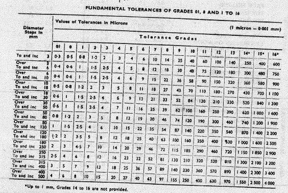
10 Dimensional Tolerances The tolerance of a dimension is defined as the difference between the upper and lower limit dimensions of the part. In order to meet the requirements of various production branches for accuracy of the product, the ISO system specifies 20 Tolerance Grades Each tolerance Grade on this system is marked "IT" with attached grade of accuracy (IT01, IT0, IT1... IT16). 10
11 ISO Tolerance Grades IT01 to IT6 For production of gauges and measuring instruments IT5 to IT12 For fits in precision and general engineering IT11 to IT16 For specification of limit deviations of non-tolerated dimensions 11
12 Tolerance Grades obtainable from Manufacturing Processes PEMP Tolerence grades and Tolerance values in microns for hole manufacturing processes diameter fine boring int grinding boring boring drilling drilling steps reaming reaming reaming reaming slot milling punching honing broaching H6 H7 H8 H9 H10 H11 upto to to to to to
13 ISO Tolerance Zones The tolerance zone is defined as a spherical zone limited by the upper and lower limit dimensions of the part. It is determined by the amount of the tolerance and its position related to the basic size. The position of the tolerance zone, related to the basic size is called the basic deviation. ISO defines 28 classes of basic deviations for holes. These classes are marked by capital letters (A, B, C,... ZC). The tolerance zone for the specified dimensions is prescribed in the drawing by a tolerance mark, which consists of a letter marking of the basic deviation and a numerical marking of the tolerance grade (e.g. H7, H8, D5, etc.). 13
14 ISO Tolerance Zones ISO defines 28 classes of basic deviations for shafts. These classes are marked by lower case letters (a, b, c,... zc). The tolerance zone for the specified dimensions is prescribed in the drawing by a tolerance mark, which consists of a letter marking of the basic deviation and a numerical marking of the tolerance grade (e.g. h7, h6, g5, etc.). 14

15 ISO Tolerance Grades and Zones 3.3 of PSG Design Data Book 15
16 16

17 Running and Sliding Fits 3.4 of PSG Design Data Book 17

18 Location and Assembly Fits 18

19 Transition and Interference Fits 3.5 of PSG Design Data Book 19

20 Transition and Interference Fits 3.6 of PSG Design Data Book 20

21 Mean Fit and Variation Values 21
22 Geometric Tolerances and Symbols 22

23 Geometric Tolerances 23
24 Geometric Tolerances 24

25 Geometric Tolerances obtainable from manufacturing Processes PEMP Table on 3.11 of PSG Design Data Book 25
26 Surface Roughness Obtainable from Manufacturing processes PEMP 26

27 Surface Roughness Obtainable from Manufacturing processes PEMP 27
28 Gauging Gauges are limit checking devices used for Go-No Go inspection of components during mass production The Go Gauge checks the maximum material condition and is designed to check dimension as well as geometry over its useful length No Go Gauge checks the minimum material condition and is designed to check only dimension at any point over its length 28

29 Plug Gauge For a Hole, the Go Gauge checks the minimum diameter and the No Go Gauge checks the maximum diameter. Holes which are within the specified tolerance will permit entry of the Go Gauge but will not permit entry of the No Go Gauge The type of Gauge used is Plug Gauge 29


30 Ring Gauge/Snap Gauge For a Shaft, the Go Gauge checks the maximum diameter and the No Go Gauge checks the minimum diameter. Shafts which are within the specified tolerance will enter the Go Gauge but not enter the No Go Gauge The type of gauges used is Ring Gauge and Snap Gauge 30

31 Thread Plug and Ring Gauges 31


32 Pin Gauges and Thickness Gauge 32


33 Case Study for Fits and Tolerances for assembly PEMP 33
34 Summary Parts made in production have an inherent variation in dimensions, geometric properties and surface finish due to variations in the materials and manufacturing equipment used Dimensions, fits and tolerances are therefore to be provided in all manufacturing drawings in addition to the 3D part models Parts and assemblies need to be made and checked with limit gauging to confirm that they meet design requirements with respect to assembly product performance, reliability, servicability and life 34
: Fits and Tolerances
 Fits and Tolerances CONTENTS Why tolerances and fits are required? Due to the inevitable inaccuracy of manufacturing methods, a part cannot be made precisely to a given dimension, the difference between
Module-3 Lecture-16 Design of limit gauges
 Metrology Prof. Dr. Kanakuppi Sadashivappa Department of Industrial and Production Engineering Bapuji Institute of Engineering and Technology-Davangere Module-3 Lecture-16 Design of limit gauges (Refer
Introduction. In engineering you are usually concerned with a number of parts or components fitting together to make an: assembly
 Limits and Fits Introduction In engineering you are usually concerned with a number of parts or components fitting together to make an: assembly To assemble components together engineers must control the
Engineering drawing. Semester I/II Mechanical Engineering Department Technical University of Gdańsk. Lecture 8
 Engineering drawing Semester I/II Mechanical Engineering Department Technical University of Gdańsk Lecture 8 Representing Tolerance Values Tolerance is the total amount a dimension may vary and is the
SYSTEM OF LIMITS, FITS, TOLERANCES AND GAUGING
 UNIT 2 SYSTEM OF LIMITS, FITS, TOLERANCES AND GAUGING Introduction Definition of limits Need for limit system Tolerance Tolerance dimensions ( system of writing tolerance) Relationship between Tolerance
IPE 381 Chapter:04 Limit, Fits and Tolerance
 IPE 381 Chapter:04 Limit, Fits and Tolerance Abdullah-Al-Mamun Lecturer, Dept. of IPE Outline Basics of Limit and Fit Interchangeable manufacturing Different types of fit Tolerance Tolerance Calculation
Fits and Tolerances. Prof Ahmed Kovacevic
 ME 1110 Engineering Practice 1 Engineering Drawing and Design - Lecture 7 Fits and Tolerances Prof Ahmed Kovacevic School of Engineering and Mathematical Sciences Room C130, Phone: 8780, E-Mail: a.kovacevic@city.ac.uk
Module 1 Fundamentals of machine design. Version 2 ME, IIT Kharagpur
 Module 1 Fundamentals of machine design Lesson 3 Brief overview of design and manufacturing Instructional Objectives: At the end of this lesson, the students should be able to understand: Concept of limits
Tolerancing. Summary
 Tolerancing Summary Summary What will we learn We will learn about tolerancing and how important this technique is to mass production. Key points If a feature s size is toleranced, it is allowed to vary
Manufacturing Science-II (EME-503)
") Time: 1 Hour B.Tech. [SEM V (ME-5 All Groups)] QUIZ TEST-1 Manufacturing Science-II ` Max. Marks: 30 Note: Attempt all the questions Q1) How metal is removed in metal cutting? Explain by giving any simple
Time: 1 Hour B.Tech. [SEM V (ME-5 All Groups)] QUIZ TEST-1 Manufacturing Science-II ` Max. Marks: 30 Note: Attempt all the questions Q1) How metal is removed in metal cutting? Explain by giving any simple
Copyright 2010 Society of Manufacturing Engineers. FUNDAMENTAL MANUFACTURING PROCESSES Holemaking - HO
 FUNDAMENTAL MANUFACTURING PROCESSES Holemaking - HO SCENE 1. HO78A, CGS: Hole Finishing Operations white text, centered on background FMP BKG, motion background SCENE 2. HO79A, SME2519, 02:26:30:00-02:26:42:00
Representation of features Geometric tolerances. Prof Ahmed Kovacevic
 ME 1110 Engineering Practice 1 Engineering Drawing and Design - Lecture 6 Representation of features Geometric tolerances Prof Ahmed Kovacevic School of Engineering and Mathematical Sciences Room C130,
GEOMETRICAL TOLERANCING
 GEOMETRICAL TOLERANCING Introduction In a typical engineering design and production environment, the designer of a part rarely follows the design to the shop floor, and consequently the only means of communication
FACULTY OF ENGINEERING DESIGN AND PRODUCTION ENGINEERING DEPARTMENT. Credit Hour System Metrology Lab 1 MDP 240 (1) Fixed gauges. Metrology laboratory
 Fixed gauges. Metrology laboratory") FACULTY OF ENGINEERING DESIGN AND PRODUCTION ENGINEERING DEPARTMENT Report On: Credit Hour System Metrology Lab 1 MDP 240 (1) Fixed gauges Metrology laboratory Class No: B.N. Student Name Remark Signature
FACULTY OF ENGINEERING DESIGN AND PRODUCTION ENGINEERING DEPARTMENT Report On: Credit Hour System Metrology Lab 1 MDP 240 (1) Fixed gauges Metrology laboratory Class No: B.N. Student Name Remark Signature
Dr Ghassan Al-Kindi - MECH2118 Lecture 9
 Dr Ghassan Al-Kindi - MECH2118 Lecture 9 Machining A material removal process in which a sharp cutting tool is used to mechanically cut away material so that the desired part geometry remains Most common
Assembly of Machine Parts
 Machine Drawing Assembly of Machine Parts Temporary Permanent Fastening Keying Fitting Welding Riveting Interference fit Machine drawing is the indispensable communicating medium employed in industries,
INSTITUTE OF AERONAUTICAL ENGINEERING (Autonomous) Dundigal, Hyderabad
 Dundigal, Hyderabad") Name Code INSTITUTE OF AERONAUTICAL ENGINEERING (Autonomous) Dundigal, Hyderabad -500 043 MECHANICAL ENGINEERING TUTORIAL QUESTION BANK : ENGINEERING METROLOGY : A50318 Class : III B.Tech I Semester Branch
Name Code INSTITUTE OF AERONAUTICAL ENGINEERING (Autonomous) Dundigal, Hyderabad -500 043 MECHANICAL ENGINEERING TUTORIAL QUESTION BANK : ENGINEERING METROLOGY : A50318 Class : III B.Tech I Semester Branch
DRAFTING MANUAL. Dimensioning and Tolerancing Rules
 Page 1 1.0 General This section is in accordance with ASME Y14.5-2009 Dimensioning and Tolerancing. Note that Rule #1 is the only rule that is numbered in the 2009 standard. All of the other rules fall
bcprecision Devices, Inc. HYDRAULIC ARBORS AND CHUCKS
 UNEQUALED WORK HOLDING ACCURACY for: grinding; balancing; inspection; boring; facing; reaming; drilling; turning; shaving; hobbing and honing b SQUARENESS r CONCENTRICITY f PARALLELISM e ROUNDNESS v ALIGNMENT
Trade of Toolmaking. Module 5: Press Tools, Jigs & Fixtures, Mouldmaking Unit 2: Blanking Tool (Unguided) Phase 2. Published by
 Phase 2. Published by") Trade of Toolmaking Module 5: Press Tools, Jigs & Fixtures, Mouldmaking Unit 2: Blanking Tool (Unguided) Phase 2 Published by SOLAS 2014 Unit 2 1 Table of Contents Document Release History... 3 Unit Objective...
Trade of Toolmaking Module 5: Press Tools, Jigs & Fixtures, Mouldmaking Unit 2: Blanking Tool (Unguided) Phase 2 Published by SOLAS 2014 Unit 2 1 Table of Contents Document Release History... 3 Unit Objective...
Machining components using vertical boring machines
 Unit 319 Machining components using vertical boring machines UAN: Level: 3 Credit value: 77 GLH: 161 Relationship to NOS: Assessment requirements specified by a sector or regulatory body: Aim: Y/600/5430
TOOL, JIG AND DIE MAKER
 MERSETA - TRAINING SCHEDULE PAGE 1 TRADE: TOOL, JIG AND DIE MAKER INDUCTION ID1 Recall applicable sections of the Manpower Training Act (No 56, 1981) with special reference to discipline and legal responsibilities.
JOB QUALIFICATION STANDARD (JQS)
") Occupation: Work Process: Maintenance Mechanic Machine Shop Practical Hours: 250 hrs. JOB QUALIFICATION STANDARD (JQS) DOL Standard: Manual Machining Fundamentals: Apply a working knowledge of metal removal
Occupation: Work Process: Maintenance Mechanic Machine Shop Practical Hours: 250 hrs. JOB QUALIFICATION STANDARD (JQS) DOL Standard: Manual Machining Fundamentals: Apply a working knowledge of metal removal
Plain bearings Wrapped bushes
 BRITISH STANDARD BS ISO 3547-5:2007 Licensed Copy: :FULLNAME, : DATE, Uncontrolled Copy, (c) BSI Plain bearings Wrapped bushes Part 5: Checking the outside diameter ICS 21.100.10 National foreword Licensed
Drawing & Design. Lecture 3. Lecturer: Dr. John Cheung
 MECH 313 Engineering Drawing & Design Lecture 3 Lecturer: Dr. John Cheung Outline Limits and tolerances Fits and allowances Surface texture Why ygive Tolerance? Manufacturing Practice is 6000 years old,
Metrology and instrumentation Indian Institute of Technology
 Metrology and instrumentation Indian Institute of Technology SOURCE: S. KALPAKJIAN BOOK SLIDE-WAY CROSS-SECTION Cross-section of a machine tool slide-way. The width, depth, angles, and other dimensions
Specification D data models
 Previous Edition Specification 2017-04 Class: Dimensions, tolerances Class No.:01 Documentation of components by means of 3D data models 516 Part name (for databases) 2009-09 3D data models 852 005 160
Total Related Training Instruction (RTI) Hours: 144
 Hours: 144") Total Related Training (RTI) Hours: 144 Learning Unit Unit 1: Benchwork and Layout Layout tools Tapping Reaming Filing Engraving Stamping Unit 2: Cutting and Drilling Cutting Operations Drilling Operations
Total Related Training (RTI) Hours: 144 Learning Unit Unit 1: Benchwork and Layout Layout tools Tapping Reaming Filing Engraving Stamping Unit 2: Cutting and Drilling Cutting Operations Drilling Operations
Mechanical Drawing. Fig 5-1
 College of Engineering 1 Mechanical Drawing Mechanical Engineering Department Mechanical Drawing Lecture 5 Keys and keyways 5-1 Introduction A key, Fig. 5.1, is usually made from steel and is inserted
Quotation Swastik Rs Advance Rs
 Quotation 77 Plain Plug Gauges H7 and Other Std With certificate Swastik / Advance / Baker make Size - mm 3 9 10 19 20 29 30 39 40 49 50 59 60 69 70 79 80 89 Advance Rs. 410 480 610 820 970 1160 1750 2200
COMPETENCY ANALYSIS PROFILE MOULD MAKER 431A (All unshaded skill sets must be demonstrated/completed)
") COMPETENCY ANALYSIS PROFILE MOULD MAKER 431A (All unshaded skill sets must be demonstrated/completed) SKILL SETS SKILLS PROTECT SELF AND OTHERS Identify health and safety hazards in the workplace. Wear,
COMPETENCY ANALYSIS PROFILE MOULD MAKER 431A (All unshaded skill sets must be demonstrated/completed) SKILL SETS SKILLS PROTECT SELF AND OTHERS Identify health and safety hazards in the workplace. Wear,
Australian Standard. ISO system of limits and fits. Part 1: Bases of tolerances, deviations and fits AS ISO 286-1:1988
 AS 1654.1 1995 ISO 286-1:1988 Australian Standard ISO system of limits and fits Part 1: Bases of tolerances, deviations and fits This Australian Standard was prepared by Committee ME/27, Engineering Tolerance
Workpiece drawing factors. Size Shape Composition Dimensions Specifications
 ITCD 301-001 Workpiece drawing factors Size Shape Composition Dimensions Specifications Tolerance Total amount of dimensional variation Designer specifies an unattainable condition Designer specifies a
ISO INTERNATIONAL STANDARD
 INTERNATIONAL STANDARD ISO 286-1 Second edition 2010-04-15 Geometrical product specifications (GPS) ISO code system for tolerances on linear sizes Part 1: Basis of tolerances, deviations and fits Spécification
Manufacturing Processes (2), IE-352 Ahmed M El-Sherbeeny, PhD Spring Manual Process Planning
, IE-352 Ahmed M El-Sherbeeny, PhD Spring Manual Process Planning") Manufacturing Processes (2), IE-352 Ahmed M El-Sherbeeny, PhD Spring 2017 Manual Process Planning Chapter Outline 2 1. Introduction 2. Manual Process Planning 3. Process Plan 4. Part Features Identification
Manufacturing Processes (2), IE-352 Ahmed M El-Sherbeeny, PhD Spring 2017 Manual Process Planning Chapter Outline 2 1. Introduction 2. Manual Process Planning 3. Process Plan 4. Part Features Identification
THE MOST IMPORTANT FACTS ABOUT SUPPORT BLOCKS
 THE MOST IMPORTANT FACTS ABOUT SUPPORT BLOCKS > Material: High quality tempering steel resp. castings. > Machining: All support blocks shown, have machined base- and contact faces. The serrated elements
ME 114 Engineering Drawing II
 ME 114 Engineering Drawing II FITS, TOLERANCES and SURFACE QUALITY MARKS Mechanical Engineering University of Gaziantep Dr. A. Tolga Bozdana Assistant Professor Tolerancing Tolerances are used to control
Tool and Die Maker Level 2
 Level 2 B2 Read and Interpret Drawings II Duration: 32 hours 32 hours 0 hours This unit of instruction introduces the Tool and Die Maker Apprentice with the knowledge and skills necessary to read and interpret
Designing for machining round holes
 Designing for machining round holes Introduction There are various machining processes available for making of round holes. The common processes are: drilling, reaming and boring. Drilling is a machining
WHAT? WHERE? HOW?
 JIGS WHAT? WHERE? HOW? Introduction Mass production aims at high productivities to reduce unit cost and inter-changeabilites to facilitate easy assembly. Jigs are useful in mass production. They provide
Chapter 23: Machining Processes: Turning and Hole Making
 Manufacturing Engineering Technology in SI Units, 6 th Edition Chapter 23: Machining Processes: Turning and Hole Making Chapter Outline 1. Introduction 2. The Turning Process 3. Lathes and Lathe Operations
Design for machining
 Multiple choice questions Design for machining 1) Which one of the following process is not a machining process? A) Planing B) Boring C) Turning D) Forging 2) The angle made between the rake face of a
Design for machining
 Design for machining Machining processes are material removal processes which are a family of shaping operation in which excess or undesired material is removed from the work piece finally remaining with
the same information given in two different 1. Dimensions should NOT be duplicated, or Dimension Guidelines Incorrect ways.
 Dimension Guidelines 1. Dimensions should NOT be duplicated, or the same information given in two different ways. Incorrect 1. Dimensions should NOT be duplicated, or the same information given in two
ENVELOPE REQUIREMENT VERSUS PRINCIPLE OF INDEPENDENCY
 ENVELOPE REQUIREMENT VERSUS PRINCIPLE OF INDEPENDENCY Carmen SIMION, Ioan BONDREA University "Lucian Blaga" of Sibiu, Faculty of Engineering Hermann Oberth, e-mail:carmen.simion@ulbsibiu.ro, ioan.bondrea@ulbsibiu.ro
Technology Workpieces and processes in the automotive industry
 Technology Workpieces and processes in the automotive industry New machining solutions for that extra productivity and cost-effectiveness MAPAL technology: Tap the potential savings during the machining
DESIGN AND FABRICATION OF GRINDING ATTACHMENT FOR LATHE MACHINE TOOL
 DESIGN AND FABRICATION OF GRINDING ATTACHMENT FOR LATHE MACHINE TOOL Pratik Chavan 1, Sanket Desale 2, Ninad Kantela 3, Priyanka Thanage 4 Prasad Bari 5 1,2,3,4 B.E. Students, Fr. C Rodrigues Institute
and mean roughness index R a of the micro-irregularities. Following are the definitions of the terms indicated in Fig. 16.1:
 It is not possible to achieve in practice, a geometrically ideal surface of a component and hence, production drawings of components must also contain information about the permissible surface conditions.
DFTG-1305 Technical Drafting Prof. Francis Ha
 DFTG-1305 Technical Drafting Prof. Francis Ha Session 5 Dimensioning Geisecke s textbook: 14 th Ed. Chapter 10 p. 362 15 th Ed. Chapter 11 p. 502 Update: 17-0508 Dimensioning Part 1 of 2 Dimensioning Summary
CURRICULUM ASSESSMENT CHECKLIST
 CURRICULUM ASSESSMENT CHECKLIST Machinist - Level 1 Apprenticeship Manitoba prescribes time and content specific curriculum standards for technical training in the trade of Machinist. To assist accreditation
Machining components using centre lathes
 Unit 305 Machining components using centre lathes UAN: Level: 3 Credit value: 77 GLH: 161 Relationship to NOS: Assessment requirements specified by a sector or regulatory body: Aim: A/600/5386 This unit
Engineering Metrology and Instrumentation
 Engineering Metrology and Instrumentation Machine-Tool Slideway Figure 35.1 Cross-section of a machine-tool slideway. The width, depth. Angles, and other dimensions all must be produced and measured accurately
SLIDE SHAFT PRODUCTS. 777 Schwab Road, Suite T, Hatfield, PA Toll Free: Fax:
 SLIDE SHAFT PRODUCTS Materials Materials of NB slide shafts are selected AISI 52100, 1060, and 0C (or equivalent) on the basis of hardenability, fatigue strength, wear resistance, and toughness. AISI
Elementary Dimensioning
 Elementary Dimensioning Standards Institutions ANSI - American National Standards Institute - creates the engineering standards for North America. ISO - International Organization for Standardization -
SEMMME219 SQA Unit Code HF3V 04 Operating CNC turning machines
 Overview This standard identifies the competences you need to carry out turning operations, in accordance with approved procedures, using Computer Numerical Control (CNC) machines, or CNC machining centres.
Chapter 23: Machining Processes: Hole Making Part A (Lathe Operations, Boring, Reaming, Tapping)
") 1 Manufacturing Processes (2), IE-352 Ahmed M El-Sherbeeny, PhD Spring 2017 Manufacturing Engineering Technology in SI Units, 6 th Edition Chapter 23: Machining Processes: Hole Making Part A (Lathe Operations,
1 Manufacturing Processes (2), IE-352 Ahmed M El-Sherbeeny, PhD Spring 2017 Manufacturing Engineering Technology in SI Units, 6 th Edition Chapter 23: Machining Processes: Hole Making Part A (Lathe Operations,
Universal Machining Chucks. 4-Jaw Vertical
 Universal Machining Chucks 4-Jaw Vertical Parts are gripped firmly by the formed jaws, ensuring high precision (deviation within 0.03mm) Large workpieces can be held tight with the low profile vise body
on site machining and grinding
 We offer custom solutions to all kind of Our Technical Design Office will find the optimal solution to your problem We carry out dimensional reports of all works we do, and ever warrant the quality that
DRAWING STANDARDS D01
 Revision E 10 Scope These Drawing Standards regulate dimensioning, tolerancing and labelling of technical documents as well as the symbols to be used. This guideline shall apply for all new parts as well
Metrology Prof. Dr Kanakuppi Sadashivappa Bapuji Institute of Engineering and Technology Davangere. Lecture 34 Pneumatic Comparators
 Metrology Prof. Dr Kanakuppi Sadashivappa Bapuji Institute of Engineering and Technology Davangere Lecture 34 Pneumatic Comparators (Refer Slide Time: 00:13) (Refer Slide Time: 00:17) I welcome you all
Locating Principles & Devices
 Locating Principles & Devices 1 LOCATING PRINCIPLES To position the work piece w.r.t. to tool, to ensure precision in machining Locating: dimensional and positional relationship b/w work piece and tool
Design for Quality, Manufacturing and Assembly Prof. G.Saravana Kumar Department of Engineering Design Indian Institute of Technology, Madras
 Design for Quality, Manufacturing and Assembly Prof. G.Saravana Kumar Department of Engineering Design Indian Institute of Technology, Madras Lecture 20 Estimation of Mold Cost for Injection Molding (Dixon
Geometric Tolerances & Dimensioning
 Geometric Tolerances & Dimensioning MANUFACTURING PROCESSES - 2, IE-352 Ahmed M. El-Sherbeeny, PhD KING SAUD UNIVERSITY Spring - 2015 1 Content Overview Form tolerances Orientation tolerances Location
NABTEB Past Questions and Answers - Uploaded online PAST QUESTIONS AND ANSWERS GENERAL METAL WORK MAY/JUNE 2009
 PAST QUESTIONS AND ANSWERS GENERAL METAL WORK MAY/JUNE 2009 1a. Enumerate TWO safety measures each as regards the use of the following hand tools. 1. Scriber 2. Chisel 3. File 4. Try-square 1. Scriber:
Manufacturing Processes (continued)
") Manufacturing (continued) Machining Some other processes Material compatibilities Process (shape) capabilities Manufacturing costs Correct pg 142, question 34i should read Fig 6.18 question 34j should
Manufacturing (continued) Machining Some other processes Material compatibilities Process (shape) capabilities Manufacturing costs Correct pg 142, question 34i should read Fig 6.18 question 34j should
Inspection and Measurement
 Inspection and Measurement Inspection An action to insure what is being manufactured conforms to the specifications by attributes use of gages: go or no-go by variables use of calibrated instruments Measurement
Datum reference frame Position and shape tolerances Tolerance analysis
 Datum reference frame Position and shape tolerances Tolerance analysis Šimon Kovář Datum reference frame Datum reference frames are typically for 3D. A typical datum reference frame is made up of three
Precision Universal Bevel Protractor, Set
 ß 37006 Protractors Measuring and laying-out tools, gauges 0 With 0-180 scale and locking screw. Standard steel, chrome-plated, scale dazzle-free and with matt-chromed finish. 37006 Arc Length of 37006...
53932 Wood Boring Bit, 78" Features. Descriptions. Manufacturer Information. Taxonomies, Classifications, and Categories.
 3804 South Street 75964-7263, TX Nacogdoches Phone: 936-569-7941 Fax: 936-560-4685 53932 Wood Boring Bit, 78" Klein Tools Catalog Number 53932 Manufacturer Klein Tools Weight per unit 0.3500 (lbs/each)
Manufacturing Process
 Unit 10: Manufacturing Process Unit code: H/601/1487 QCF level: 4 Credit value: 15 Aim This unit will develop learners knowledge of manufacturing processes and techniques that can be applied to a range
ROOP LAL Unit-6 Drilling & Boring Mechanical Engineering Department
 Lecture 4 Notes : Drilling Basic Mechanical Engineering ( Part B ) 1 Introduction: The process of drilling means making a hole in a solid metal piece by using a rotating tool called drill. In the olden
Dimensioning: There are a few simple best practices which can help us dimension a working drawing:
 Dimensioning and Tolerancing Prepared by: Michael Hypes Cornell University Preparation: One of the most common problems for new designers is choosing dimension that do not reflect the purpose of the part.
Fasteners Dowel Pins Extractable Dowels
 Extractable Dowels & Ext. Dowels Dowels are solid pins, usually precision ground to narrow limits to permit accurate fitting. Precision dowels are traditionally used to hold parts together in a fixed alignment,
Chapter 2: Dimensioning Basic Topics Advanced Topics Exercises
 Chapter 2: Dimensioning Basic Topics Advanced Topics Exercises Dimensioning: Basic Topics Summary 2-1) Detailed Drawings 2-2) Learning to Dimension 2-3) Dimension Appearance and Techniques. 2-4) Dimensioning
Promotion of TVET Viet Nam. Vietnamese-German Development Cooperation. Mechatronics MODULES
 Promotion of TVET Viet Nam Vietnamese-German Development Cooperation Mechatronics MODULES Promotion of TVET Viet Nam Promotion Mechatronics of TVET Viet Nam Vietnamese-German Development Cooperation Module
Recommended Dimensional Guidelines for Single Screws
 The Society of the Plastics Industry s Machinery Component Manufacturers Division Recommended Dimensional Guidelines for Single Screws The following recommendations for single screws of injection molding
VALLIAMMAI ENGINEERING COLLEGE
 SRM Nagar, Kattankulathur 603 203 II SEMESTER CC5291- DESIGN FOR MANUFACTURE, ASSEMBLY AND ENVIRONMENTS Regulation 2017 Academic Year 2017 18 Prepared by Mr. K.VENKATESAN, Assistant Professor (O.G) SRM
Unit4 31. UnitS 39. Unit 6 47
 Preface..................... xi About the Author......... xiii Acknowledgments... xiv Unit 1 1 Bases for Interpreting Drawings........ I Visible Lines............. 3 Lettering on Drawings... 3 Sketching...
Lathe. A Lathe. Photo by Curt Newton
 Lathe Photo by Curt Newton A Lathe Labeled Photograph Description Choosing a Cutting Tool Installing a Cutting Tool Positioning the Tool Feed, Speed, and Depth of Cut Turning Facing Parting Drilling Boring
Preparing and using CNC Machining Centres F/508/4727
 Unit Title Ofqual unit reference number (code) Organisation Reference Preparing and using CNC Machining Centres F/508/4727 QU051501 Unit Level Level 2 Unit Sub Level None GLH 64 Unit Credit Value 14 Sector
Broaches The basic characteristic
 Broaches The basic characteristic Broaches handle mass production with high accuracy and high efficiency. It is very important to point out that complex shapes can be steadily produced without requiring
Twin screw and barrel are the heart of extruders and play very crucial role in extruder.
 SHREE RADHEKRISHNA EXTRUSIONS PVT.LTD, a renewed engineering company has been Serving in the field of manufacturing screw & barrel for last more then 20 years. Radhekrishna Extrusions manufactures screw
KTSB14 Step Drill Bit #14 Double-Fluted, 3/16 to 7/8" Descriptions Description STEP DRILL BIT #14 DOUBLE-FLUTED, 3/16 TO 7/8"
 3804 South Street 75964-7263, TX Nacogdoches Phone: 936-569-7941 Fax: 936-560-4685 KTSB14 Step Drill Bit #14 Double-Fluted, 3/16 to 7/8" Klein Tools Catalog Number Manufacturer Weight per unit Product
Machinist Level 4 Rev. December 12, 2012
 Machinist Level 4 Machinist Unit: A14 Reconditioning Level: Four Duration: 12 hours Theory: Practical: 12 hours 0 hours Overview: This unit of instruction is designed to introduce knowledge of the procedures
Introduction to Machining: Lathe Operation
 Introduction to Machining: Lathe Operation Lathe Operation Lathe The purpose of a lathe is to rotate a part against a tool whose position it controls. It is useful for fabricating parts and/or features
AC : CLARIFICATIONS OF RULE 2 IN TEACHING GEOMETRIC DIMENSIONING AND TOLERANCING
 AC 2007-337: CLARIFICATIONS OF RULE 2 IN TEACHING GEOMETRIC DIMENSIONING AND TOLERANCING Cheng Lin, Old Dominion University Alok Verma, Old Dominion University American Society for Engineering Education,
Jig and Fixture Design. Chapter 1: Types and Functions of Jigs and Fixtures
 Jig and Fixture Design Chapter 1: Types and Functions of Jigs and Fixtures Purpose of Tool Design Objectives: Provide simple, easy-to-operate tools for maximum efficiency Reduce manufacturing expenses
CHAPTER5 5 ZERO DEFECT MANUFACTURING IN THE PRODUCTION OF IMPELLER THROUGH THE APPLICATION OF CAD / CAE
 33 CHAPTER5 5 ZERO DEFECT MANUFACTURING IN THE PRODUCTION OF IMPELLER THROUGH THE APPLICATION OF CAD / CAE 5.1 INTRODUCTION In the first place of research, CAD/CAE was applied to achieve ZERO DEFECT MANUFACTURING
Preparing and using lathes for turning operations
 Unit 011 Preparing and using lathes for turning Level: 2 Credit value: 15 NDAQ number: 500/9514/6 Unit aim This unit covers the skills and knowledge needed to prove the competences required to cover a
SEMPEO SQA Unit Code FP2J 04 Preparing and using CNC turning machines
 Overview This standard covers a broad range of basic computer numerical control (CNC) turning competences that will prepare you for entry into the engineering or manufacturing sectors, creating a progression
Design and Manufacturing of a holding fixture to test the tensile strength of a flat specimen
 Design and Manufacturing of a holding fixture to test the tensile strength of a flat specimen Joginder Singh Associate Professor, Department of Mechanical Engineering, Dr. M.R.Tyagi Professor, Department
Roll No. :.. Invigilator s Signature :.. CS/B.Tech (ME)/SEM-5/ME-504/ TECHNOLOGY OF MACHINING. Time Allotted : 3 Hours Full Marks : 70
/SEM-5/ME-504/ TECHNOLOGY OF MACHINING. Time Allotted : 3 Hours Full Marks : 70") Name : Roll No. :.. Invigilator s Signature :.. CS/B.Tech (ME)/SEM-5/ME-504/2009-10 2009 TECHNOLOGY OF MACHINING Time Allotted : 3 Hours Full Marks : 70 The figures in the margin indicate full marks. Candidates
Name : Roll No. :.. Invigilator s Signature :.. CS/B.Tech (ME)/SEM-5/ME-504/2009-10 2009 TECHNOLOGY OF MACHINING Time Allotted : 3 Hours Full Marks : 70 The figures in the margin indicate full marks. Candidates
Contents DIN 50125:
 14 Contents Foreword... 3 1 Scope... 4 2 Normative references... 4 3 Terms and definitions... 4 4 Types, dimensions, and designation... 4 4.1 General... 4 4.2 Type A test pieces... 6 4.3 Type B test pieces...
ISO 3548 INTERNATIONAL STANDARD. Plain bearings Thin-walled half bearings with or without flange Tolerances, design features and methods of test
 INTERNATIONAL STANDARD ISO 3548 Second edition 1999-12-1 Plain bearings Thin-walled half bearings with or without flange Tolerances, design features and methods of test Paliers lisses Demi-coussinets minces
Materials & Processes in Manufacturing
 2003 Bill Young Materials & Processes in Manufacturing ME 151 Chapter 21 Fundamentals of Chip Type Machining Processes 1 Materials Processing 2003 Bill Young 2 Introduction Machining is the process of
Measuring and Laying-Out Tools, Testing Instruments
 ß 7006 0 With 0-180 scale and locking screw. Protractors Measuring and Laying-Out Tools, Testing Instruments Standard steel, chrome-plated, scale dazzle-free and with matt-chrome finish. 7006 Arc Ø Blade
ANSI ORIFICE FLANGES METAL-KOREA
 METAL-KOREA ANSI ORIFICE FLANGES ORIFICE FLANGES are widely used in conjunction with orifice meters for measuring the rate of flow of liquids and gases. They are basically the same as standard welding
Annual Report for Assessment of Outcomes Machine Manufacturing Technology (MMT) Program
 Program") Annual Report for Assessment of Outcomes 2011-2012 Machine Manufacturing Technology (MMT) Program 1. Describe changes that have been implemented towards improving students attainment of outcomes that resulted
Annual Report for Assessment of Outcomes 2011-2012 Machine Manufacturing Technology (MMT) Program 1. Describe changes that have been implemented towards improving students attainment of outcomes that resulted
CHAPTER 53 MACHINERY REPAIRMAN (MR) NAVPERS E CH-65
 NAVPERS E CH-65") CHAPTER 53 MACHINERY REPAIRMAN (MR) NAVPERS 18068-53E CH-65 Updated: January 2016 SCOPE OF RATING GENERAL INFORMATION MACHINERY REPAIR APPRENTICE FABRICATIONS AND MANUFACTURING MACHINE OPERATIONS PRE-MANUFACTURING
CHAPTER 53 MACHINERY REPAIRMAN (MR) NAVPERS 18068-53E CH-65 Updated: January 2016 SCOPE OF RATING GENERAL INFORMATION MACHINERY REPAIR APPRENTICE FABRICATIONS AND MANUFACTURING MACHINE OPERATIONS PRE-MANUFACTURING
COMPETENCY ANALYSIS PROFILE GENERAL MACHINIST 429A. (All unshaded skill sets must be demonstrated/completed)
") COMPETENCY ANALYSIS PROFILE GENERAL MACHINIST 429A (All unshaded skill sets must be demonstrated/completed) SKILL SETS SKILLS PROTECT SELF AND OTHERS Identify health and safety hazards. Wear, adjust, and
COMPETENCY ANALYSIS PROFILE GENERAL MACHINIST 429A (All unshaded skill sets must be demonstrated/completed) SKILL SETS SKILLS PROTECT SELF AND OTHERS Identify health and safety hazards. Wear, adjust, and