COMMON SYMBOLS/ ISO SYMBOL ASME Y14.5M ISO FEATURE CONTROL FRAME DIAMETER/ SPHERICAL DIAMETER/ AT MAXIMUM MATERIAL CONDITION
|
|
|
- Martina Manning
- 5 years ago
- Views:
Transcription
1 1 82 COMMON SYMBOLS/ Shown below are the most common symbols that are used with geometric tolerancing and other related dimensional requirements on engineering drawings. Note the comparison with the ISO standards. Most of the symbology is identical. There are a few symbols that are used in the ASME Y 14.5, 1994 standard that are being proposed for the ISO standards. The symbols marked with an x are new or revised from the previous Y14.5M, 1982 standard. ISO ASME Y 14.5, 1994 ISO x Y14.5M, 1982 SYMBOL ASME Y14.5M ISO FEATURE CONTROL FRAME DIAMETER/ SPHERICAL DIAMETER/ AT MAXIMUM MATERIAL CONDITION AT LEAST MATERIAL CONDITION REGARDLESS OF FEATURE SIZE NONE/ NONE/ PROJECTED TOLERANCE ZONE X FREE STATE/ X TANGENT PLANE (Proposed) X STATISTICAL TOLERANCE NONE/ X RADIUS/ R R X CONTROLLED RADIUS / CR NONE/ SPHERICAL RADIUS/ SR SR X BASIC DIMENSION/ (theoretically exact dimension in ISO) ISO DATUM FEATURE * * DATUM TARGET TARGET POINT/ DIMENSION ORIGIN REFERENCE DIMENDION/ ( 50 ) ( 50 ) (Auxiliary dimension in ISO) /ISO 1
2 2 82 NUMBER OF PLACES / 8x 8x COUNTERBORE/SPOTFACE / COUNTERSINK/ DEPTH/DEEP/ SQUARE/ ALL AROUND/ NONE DIMENSION NOT TO SCALE ARC LENGTH/ X BETWEEN/ NONE SLOPE/ CONICAL TAPER/ ENVELOPE PRINCIPLE NONE(implied)/ Note: * May be filled or not filled/ * RADIUS, CONTROLLED RADIUS/ There are two types of radii tolerance that can be applied, the radius and controlled radius. The radius (R) tolerance is for general applications. The controlled radius (CR) is used when it is necessary to place further restrictions on the shape of the radius, as in high stress applications. /R (CR) Note: This is a change from the previous editions of the Y14.5 standard. The definition of the tolerance zone for the former term tangent radius, previously noted by the symbol R, is now meant to apply to a controlled radius (symbol CR). / Y14.5 R CR 2
3 3 82 STATISTICAL TOLERANCING SYMBOL/ Often, tolerances are calculated on an arithmetic basis. Tolerances are assigned to individual features on a component by dividing the total assembly tolerance by the number of components and assigning a portion of this tolerance to each component. When tolerances are stacked up in this manner, the tolerance may become very restrictive or tight. Statistical tolerancing is the assignment of tolerances to related components of an assembly on the basis of sound statistics. An example is: the assembly tolerance is equal to the square root of the sum of the squares of the individual tolerances. Statistical tolerancing may be applied to features to increase tolerances and reduce manufacturing cost. To ensure compatibility, the larger tolerance identified by the statistical tolerance symbol may only be used where appropriate statistical process control will be used. A note such as the one shown below shall be placed on the drawing. / 3
4 4 82 Note:/ FEATURES IDENTIFIED AS STATISTICALLY TOLERANCED SHALL BE PRODUCED WITH STATISTICAL PROCESS CONTROLS, OR TO THE MORE RESTRICTIVE ARITHMETIC LIMITS. / In some cases, it may be desirable to state only the statistical tolerance and the arithmetic number will not be shown. In this case, a note such as the following must be placed on the drawing. FEATURES IDENTIFIED AS STATISTICALLY TOLERANCED SHALL BE PRODUCED WITH STATISTICAL PROCESS CONTROLS. / For additional information on statistical tolerancing, see appropriate statistics or engineering design manuals. / NONRIGID PARTS-FREE STATE CONDITION/ - Unless otherwise specified, all dimensioning and tolerancing applies in a Free State condition with no restraint. Some parts, such as sheet metal, thin metal, plastics and rubber are no rigid in nature. It may be necessary to specify design requirements on the part in a natural or Free State as well as in a restrained condition. The restraint or force on the nonrigid parts is usually applied in such a manner to resemble or approximate the functional or mating requirements. 4
5 5 82 A note or specification on the drawing should explain how the part is restrained and the force required to facilitate the restraint. A sample note can be found on the drawing below. If any of the part specifications are to be verified in a free state, the designer may specify this requirement with the words FREE STATE or the free state symbol. The free state symbol is a F in a circle. The free state symbol means that dimensions and tolerances that have the free state symbol applied are checked in the free state and not in the restrained condition. F The free state symbol is applied by placing it next to or associating it with the required dimensions and tolerances. If it is applied in a feature control frame, it always follows the feature tolerance and any modifiers. / 4 M5 A 5
6 6 82 FEATURE CONTROL FRAME / A feature control frame states the requirements or instructions for the features to which it is attached. / SYMBOLS THAT CAN BE FOUND IN A FEATURE CONTROL FRAME/ All of the symbols below can be found inside a feature control frame. The symbols for projected tolerance zone, free state, tangent plane and statistical tolerance always follow the material condition modifier The minimum height of the projected tolerance zone can be specified in the feature control frame or in the view on the drawing in which it applies. If it is applied in the feature control frame, it follows the projected tolerance zone symbol. TERM/ SYMBOL/ FEATURE CONTROL FRAME/ DIAMETER/ SPHERICAL DIA/ MAXIMUM MATERIAL COND/ LEAST MATERIAL COND/ PROJECTED TOL ZONE/ FREE STATE/ TANGENT PLANE/ STATISTICAL TOLERANCE/ REGARDLESS OF FEATURE SIZE*/ * *The RFS symbol has been eliminated from the ASME Y 14.5M, 1994 standard. It is applicable in earlier versions. /*RFS ASME Y 14.5M,
7 7 82 DATUM FEATURE SYMBOL/ Y 14.5M, 1982 AND EARLIER Y14.5M, 1994 AND ISO /Y 14.5M, 1982 / Y14.5M, 1994 ISO MATERIAL CONDITION MODIFIERS DEFINITIONS/ - In geometric tolerancing there is often a need to refer to a particular feature of size at its largest size, smallest size or regardless of feature size. The terms maximum material condition (MMC), least material condition (LMC) and regardless of feature size (RFS) allow us to do this. (MMC), (LMC) RFS These terms can only be used when referring to features of size such as holes, slots, tabs, pins, etc. these terms have no meaning when applied to non-features of size such as plane surfaces. The application or implication of these material condition modifiers inside the feature control frame can have a substantial effect on the tolerance. See discussion on maximum material condition later in text. MAXIMUM MATERIAL CONDITION-ABBREVIATION (MMC) SYMBOL / - MMC The condition where the feature contains the maximum material within the stated limits of size for example, the largest pin or smallest hole. / LEAST MATERIAL CONDITION-ABBREVIATION (LMC) SYMBOL / LMC The condition where the feature contains the least material within the stated limits of size-for example, the largest hole or smallest pin. / 7
8 8 82 REGARDLESS OF FEATURE SIZE-ABBREVIATION (RFS)/ RFS The term used to indicate that a geometric tolerance applies at any increment of size of the feature within its size limits. / In the current ASME Y 14.5M, 1994 standard there is no symbol for RFS. (Unless otherwise specified all geometric tolerances are implied RFS. See rule 2.) In previous editions of the Y14.5 standard the symbol was used for RFS. / ASME Y 14.5M, 1994 RFS RFS 2 Y14.5 RFS MMC & LMC DEFINITION/MMC&LMC MMC SIZE LMC SIZE EFFECT OF MAXIMUM MATERIAL CONDITION/ A geometric tolerance (size features only) may be applied on an MMC basis by placing the circle M symbol in the feature control frame following the feature tolerance. This will have a substantial effect on the allowable position tolerance. The allowable position tolerance is dependent on the actual mating size of the considered feature. / M MMC The allowable geometric tolerance for the feature applies when the feature is produced at its maximum material condition (smallest hole or largest pin). If the considered feature s size departs from its maximum material condition, an increase in the allowable geometric tolerance is permitted equal to the amount of the feature s 8
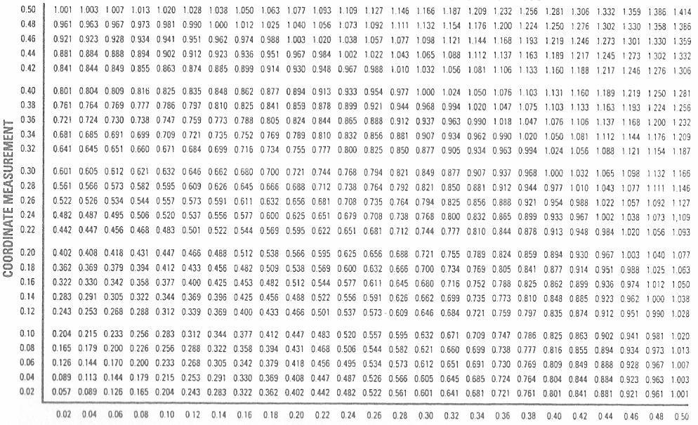
9 9 82 departure from MMC. Consider the part shown below. The circle M modifier in the feature control frame states that the features must be positioned within a.005 diameter tolerance zone when the features are at their maximum material condition. The maximum material condition (MMC) for the holes is.260 dia. If the features depart from the.260 dia. size, they can have additional position tolerance equal to the amount of their departure from MMC. / M MMC MMC CONCEPT/ DIAMETER FEATURE SIZE / DIAMETER TOL ZONE ALLOWED /
10 10 82 EFFECT OF LEAST MATERIAL CONDITION/ A geometric tolerance (size features only) may be applied on an LMC basis by placing the circle L symbol in the feature control frame following the feature tolerance. This will have a substantial effect on the allowable position tolerance. The allowable position tolerance is dependent on the actual mating size of the considered feature. / L LMC The allowable geometric tolerance for the feature applies when the feature is produced at its least material condition (smallest pin or largest hole). If the considered feature s size departs from its least material condition, an increase in the allowable geometric tolerance is permitted equal to the amount of the feature s departure from LMC. Consider the part below. The circle L modifier in the feature control frame states that the features must be positioned within a.005 diameter tolerance zone when the features are at their least material condition. The least material condition for the holes is.268 diameter. If the features depart from the.268 dia. size, they can have additional position tolerance equal to the amount of departure from LMC. / L LMC LMC CONCEPT/ 10
11 11 82 DIAMETER FEATURE SIZE / DIAMETER TOL ZONE ALLOWED / EFFECT OF REGARDLESS OF FEATURE SIZE RFS/ Geometric tolerances (size features only) are implied on an RFS basis by implication. The modifier rule #2 states that unless otherwise specified, all geometric tolerances are by default implied to apply at RFS. Since all geometric tolerances apply at RFS, there is no need for an RFS symbol, and it has been eliminated in the ASME Y14.5M-1994 standard In past editions of the Y14.5 standard, the RFS symbol, which is an S in a circle, was specified for position tolerances. See modifier rules for more information. / RFS 2 RFS. RFS, RFS ASME Y14.5M-1994 Y14.5, RFS S If a geometric tolerance is by implication applied RFS, the specified allowable geometric tolerance is independent of the actual size of the considered feature. The allowable geometric tolerance is limited to the specified value regardless of the actual size of the feature. / RFS, Consider the part below. Since no modifier is specified in the feature control frame following the feature tolerance, this tolerance is implied to apply RFS. The features must be positioned within a.005 dia tolerance regardless of their feature size. This means that regardless of the size of the features being positioned, they have a.005 dia position tolerance and no more. If the holes get large or small, the position tolerance remains.005 dia. The RFS condition is more restrictive than the MMC or LMC concept. / RFS RFS MMC LMC 11
12 12 82 RFS CONCEPT / MODIFIER RULES CURRENT AND FORMER PRACTICES/ Current ASME Y14.5M, 1994 and ISO rule #2(old rule #3eliminated) / ASME Y14.5M, 1994 ISO 2 3 RFS applies for all geometric tolerances with respect to the individual tolerance, datum reference, or both, where no modifying symbol is specified. MMC and LMC must be specified where required. / RFS MMC LMC Former practice ANSI Y 14.5M, 1982/ - ANSI Y 14.5M,
13 13 82 Rule #2 MMC, LMC and RFS must be specified for individual tolerances and datum references for all position tolerances. / 2 MMC, LMC RFS Rule#3- RFS applies for individual tolerances and datums on all other geometric tolerances. MMC and LMC must be specified where it is required. / 3 RFS. MMC LMC Former practice ANSI Y 14.5M, 1973 / Rule #2 MMC applies for individual tolerances and datum references for position. RFS and LMC must be specified where it is required. / 2 MMC RFS LMC Rule #3 RFS applies for individual tolerances and datums on all other geometric tolerances. MMC and LMC must be specified where it is required. / 3 RFS. MMC LMC RULES FOR SCREW THREADS, GEARS AND SPLINES / Each tolerance of orientation, position or datum reference for a screw thread applies to the axis of the thread derived from the pitch cylinder. Where an exception to this practice is necessary, the specific feature of the screw thread (such as MAJOR DIA or MINOR DIA) shall be stated under the feature control frame or adjacent to the datum feature symbol, as applicable. SCREW THREADS/ 13
14 14 82 Unless otherwise specified, on screw threads, all geometric tolerances and datum references apply to the pitch diameter. / GEARS AND SPLINES / Each tolerance of orientation, position or datum reference specified for features other than screw threads, such as gears and splines, must designate the specific feature of the gear or spline to which each applies (such as MAJOR DIA, PITCH DIA, PD, or MINOR DIA) This information is stated under the feature control frame or under the datum feature symbol, as applicable. PD, All geometric tolerances and datum references specified for gears and splines must designate the specific feature to which it applies. / TYLOR PRINCIPLE (RULE #1, ENVELOPE PRINCIPLE)/ - 1 The Taylor principle is a very important concept that defines the size and form limits for an individual feature of size. The Taylor principle is widely accepted by the United States and the international standards organization (ISO). The ISO standards also allow the principle of independency which does not include form within the size limits. Depending on the particular standards invoked, either case may apply. In some cases, the circle E is used to designate features that must conform to the Taylor principle. See ISO standards ISO 8015 and ISO 1938 for additional information. ISO ISO E ISO ISO 14
15 ISO 1938 LIMITS OF SIZE / Unless otherwise specified, the limits of size of a feature prescribe the extent within which variations of geometric form, as well as size, are allowed. This control applies solely to individual features of size. INDIVIDUAL FEATURE OF SIZE TAYLOR PRINCIPLE (RULE #1) / 1 Where only a tolerance of size is specified, the limits of size of an individual feature prescribe the extent to which variations in its geometric form, as well as its size, are allowed. / THIS ON THE DRAWING/ MEANS THIS / -.498/ a. The surface or surfaces of a feature shall not extend beyond a boundary (envelope) of perfect form at MMC. This boundary is the true geometric form represented by the drawing. No variation in form is permitted if the feature is produced at its MMC limit of size. / b. Where the actual local size of a feature has departed from MMC toward LMC, a variation in form is allowed 15
16 16 82 equal to the amount of such departure. / MMC LMC c. There is no requirement for a boundary of perfect form at LMC. Thus, a feature produced at its LMC limit of size is permitted to vary from true form to the maximum variation allowed by the boundary of perfect form at MMC. / VIRTUAL CONDITION / Depending upon its function, a feature may be controlled by tolerances such as size, form, orientation and location. Consideration must be given to the collective effects of these factors in determining the clearances between mating parts and in establishing gage feature sizes. The collective effect of these factors is termed virtual condition. / Virtual condition is a constant boundary generated by the collective effects of a size feature s specified MMC or LMC material condition and the geometric tolerance for that material condition. / MMC LMC The pin in the illustration below has two virtual sizes. The.257 diameter virtual size is a result of the perpendicularity tolerance relative to datum A. the.262 diameter virtual size is a result of the position tolerance relative to datums A, B and C. the virtual sizes on this part could also be called outer boundary. It can also be viewed as a 3D solid. / A A,B,C 3D 16
17 A.257 A,B C.262 GEOMETRIC TOLERANCING APPLIED TO AN ANGLE BLOCK/ Geometric tolerancing is a very clear and concise three dimensional mathematical language for communicating product definition. A fully geometrically toleranced product drawing is shown in the top view. In the bottom view, the produced part is shown in the datum reference frame established by datum features A, B and C. the surfaces must lie within the specified tolerance zones. A,B,C THIS ON THE DRAWING/ 17
18 18 82 MEANS THIS ON PRODUCED PART/ A B THE DATUM REFERENCE FRAME (DRF)/ DRF The datum reference frame is the frame of reference to which all the requirements are attached. In geometric tolerancing we can relate engineering, manufacturing and inspection together by using this datum reference frame. The three planes are called the primary plane, the secondary plane and the tertiary plane. The datum reference frame is made up of a series of individual components. The individual components are planes, axis, and points. 18
19 19 82 Datums and the datum reference frame indicate the origin of a dimensional relationship to a toleranced feature or features of a part. When a feature serves as a datum feature, its true geometric counterpart actually establishes the datum. Since measurements cannot be made from a true geometric counterpart, which is theoretical, simulated datums are assumed to exist and be simulated with our manufacturing, processing and inspection equipment such as the bed on a machine, a collet or chuck, gage pin, a surface plate, angle plate etc. measurements then originate from the simulated planes or axis that the manufacturing or inspection equipment simulates and not the features themselves. ) A () Datum plane A is established by the datum features surface contacting on the high points of a simulated perfect plane Measurements originate from the plane and not the part. / A SPECIFIED DATUMS CLEARLY DEFINE DESIGN INTENT/ The part below has four holes located in relation to the datums. The requirements for the holes are shown in the feature control frame along with the specified datums. The datums identify how the part is located in the datum reference frame. 19
20 The order of the datums in the feature control frame specifies the order in which to load the imperfect part in the perfect datum reference frame. We then measure from the DRF and not the part. / DRF MEANS THIS / If the order of the datums in the feature control frame is changed, it will change the order in which the part is loaded in the feature control frame. / MEANS THIS / 20
21 21 82 DATUM REFERENCE FRAME / In geometric tolerancing we can relate engineering, manufacturing and quality together by placing parts in a datum reference frame. Each unsupported object or part has six degrees of freedom. The part must be fixed in relation to this datum framework in order to stop this freedom. The part is related to the primary datum plane by contacting 3 points. It is related to the secondary datum by contacting a minimum of two points. It is then related to the tertiary datum by contacting a minimum of one point. PLACEMENT OF DATUM FEATURE SYMBOL IS VERY IMPORTANT / 21
22 22 82 DATUM FEATURES WITHOUT SIZE/ If the datum feature is a plane surface, the datum feature symbol is attached to the surface or an extension line of the surface as shown below. This will establish a datum plane. TRUE GEOMETRIC COUNTERPART OF DATUM FEATURES WITHOUT SIZE / M H K N L 22
23 23 82 DATUM FEATURES WITH SIZE / If the datum feature is a feature of size, the datum feature symbol is attached to or associated with the size dimension. By attaching or associating the datum feature symbol with a particular size dimension, it defines a specific point, axis or median plane that is derived from that feature as the datum. TRUE GEOMETRIC COUNTERPART OF DATUM FEATURES WITH SIZE / B E A 23
24 24 82 PARTIAL DATUM FEATURES/ In some cases only a particular area of a feature will serve as a datum feature. This may be specified by the use of a thick chain line drawn parallel to the surface profile and dimensioned as to the required length and width. If the area needs clarification, it may by cross hatched. Partial datum may also be specified by means of a note or datum target. See examples below. Where a datum is established by two datum features (two slots, two diameters etc.), both datum reference letters are entered in a single datum compartment in the feature control frame and separated by a dash. 24
25 25 82 ESTABLISHING A DRF AND QUALIFYING DATUM FEATURES PLANE SURFACES / DRF - DRF DRF 25
26 26 82 H L H P H L DATUM TARGETS/ Datum targets may be used to establish a datum reference frame. This occurs because of manufacturing or fixturing concerns or part surface irregularities. Examples of this application might be castings, forgings, sheet metal parts, plastic parts and weldments. / 26
27 27 82 This is an example of a verification or set up fixture illustrating the datum target concept. The datum reference frame is established by three target areas on the primary feature A, two target lines on datum B, and one target point on datum feature C. A, B C B C A
28 28 82 ROUND PART WITH SLOT / The part below mounts on the right hand face, the pilot and the key. These features are identified as datum features and are related to each other by the perpendicularity and position tolerances. The holes and outside contour have been related to the datum features by the position and profile tolerances. The.060 profile tolerance on the outside contour controls size, form, location and orientation The functional gage or boundaries shown below reflect the geometric controls above. Since the features and datums are all applied at MMC, all the features may shift and/or displace as long as they meet the requirements set forth below. / MMC 28
29 29 82 MMC MMC SAMPLE INSPECTION SET-UP FOR ROUND PART WITH SLOT / MMC The illustration above is a sample open set-up inspection procedure for the verification of the round part in the previous example. Notice that the front face, datum feature A, is leveled or balanced with shims to make it parallel with the angle plate. The virtual size of the pilot is centered and the part is anti-rotated with the slot to set up the datum reference frame. All measurements are made from the origin point. / A 29
30 30 82 This part can also be verified with a coordinate measuring machine (CMM). The front face is leveled, the origin is set at the pilot and the part is oriented by the slot. / CMM Since the MMC modifier is referenced on the features and datum features, additional tolerance is available as the datum features and features depart from virtual size. / MMC The geometric tolerancing defines the product without defining the measurement procedure. All measurement procedures have associated uncertainty or risk. Some procedures will have more risk than others. This is called methods divergence. This part can also be verified with calipers to provide a rough check. The type of verification procedure is defined in the measurement plan. The measurement plan is designed by the quality engineer with knowledge of the manufacturing process. DATUM FEATURES OF SIZE EFFECT OF MODIFIERS/ - A group of features may be controlled relative to a datum feature at MMC as shown below. Datum feature B at MMC establishes the location of the axis of the datum reference frame (DRF) for the location of all the features. As datum feature B departs from MMC, its axis may be displaced relative to the datum B at MMC axis in a diameter zone equal to the difference between the virtual size and the actual virtual size. BDRF B B THIS ON THE DRAWING / 30
31 B B B MMC B DRF B B The effect of a datum modifier is accommodated automatically in a functional gage as shown below. The datum feature and the related features must fall within the appropriate tolerance zone. As the datum feature and related features depart from their stated material condition they may displace and shift as long as they clear the virtual size pins or remains within the profile tolerance zones. Notice that the datum modifier has no effect on the relationship between the features. Unless otherwise stated there is an implied simultaneous requirement between all the features and the datum features. 31
32 32 82 If the produced part were to be evaluated using a CMM or open set-up inspection techniques the shift of the datum feature may also have to taken into account. If inspection zeroed in on the datum feature and all the related features checked good the part would pass inspection. If the part checked bad the zero or origin could be reset in a diameter zone equal to the departure of the feature from its virtual size to its actual virtual size. It is often explained that the features shift as a group, but in actuality it can be seen that the actual datum features does the shifting or displacement relative to the group of related features. The datum shift can be easily calculated with the paper gage concept or accommodated with functional gaging techniques. DATUM FEATURES AT VIRTUAL CONDITION/ A virtual condition exists for a datum feature of size where its axis or center plane is controlled be a geometric tolerance. In such cases, the datum feature applies at its virtual condition even though it is referenced at MMC or LMC. Where a virtual condition equal to the maximum material condition or least material condition is required, a zero tolerance at MMC or LMC is specified. MMC LMC, MMC LMC SIMULTANEOUS REQUIREMENT/ The simultaneous requirement concept applies to both position and profile specifications. It does not apply to the lower segment in a composite tolerance. 32
33 33 82 / Multiple patterns of features, located by basic dimensions from common datum features of size, are considered a single composite pattern if their respective feature control frames contain the same order of precedence with the same material condition modifiers. If such an interrelationship is not required between patterns of features, the notation SEP REQT is placed under the feature control frame. This allows each pattern of features to shift and/or rotate independently about the established datum reference frame. / SEP REQT FUNCTIONAL GAGE OR 3D BUNDARIES ILLUSTRATING VIRTUAL SIZES FOR SIMULTANEOUS REQUIREMENT/ 3D The sample functional gage shown above will verify all the features at once. The gage is for illustration only, as other methods could be used as well. In open set-up procedures, care should be taken when datum shift or feature rotation is factored into the acceptance criteria. Remember, datum shift and rotation must be factored to all the features as a group, rather than allowing each pattern of features to shift independently as the datum feature departs from MMC. 33
34 34 82 MMC. FLATNESS/ Flatness is the condition of a surface having all elements in one plane. A flatness tolerance specifies a tolerance zone defined by two parallel planes within which the surface must lie The surface must lie between two parallel planes.002 apart. In addition, the surface must be within the specified limits of size or location. / / Flatness is a 3D tolerance. Flatness is a form tolerance and therefore datums are not allowed. Flatness is a surface control so the modifiers MMC, LMC and RFS are not applicable. / 3D MMC, LMC RFS FLATNESS VERIFICATION/ 34
35 35 82 There are many ways to check a flatness specification. Some are better than others. Each method will give a different answer. This is called methods divergence. As with verifications for any geometric tolerance, the method or procedure used for verification will depend on many factors. How many parts are there to check? Is this the 1 st part produced or the 1000 th? Is the tolerance well within the process capability? Are statistical process controls being done? How tight is the tolerance? What kind of equipment is available? Is it an in-process check or a final check? How big is the budget? All of these factors and many more will have an effect on how the part is verified. The procedures for verification should be recorded in a dimensional measurement plan and coordinated with anyone who is involved with the part. The measurement techniques and procedures shown below are for illustration and background information. These procedures are intended to assist the reader in understanding the concepts. In addition to the methods shown below, a coordinate measuring machine (CMM) can also be used. VERIFICATION METHODS FOR FLATNESS/ 3 35
36 36 82 STRAIGHTNESS LINE ELEMENTS/ - Straightness, line elements is a condition where an element of a surface is a straight line. The tolerance specifies a zone within which the considered line element must lie. A straightness tolerance is applied in the view where the elements to be controlled are represented by a straight line. Note the feature control frame is directed to the surface. / Each longitudinal element of the surface must lie between two parallel lines.003 apart where the two lines and the nominal axis of the part share a common plane. In addition, the feature must be within the specified limits of size and the boundary of perfect form at MMC. Straightness, line elements will control waisted, barreled, and bent shapes, it does not control taper. / MEANS THIS MMC
37 37 82 Straightness, Line elements controls the longitudinal elements of the feature. Straightness is a form tolerance, therefore datums are not allowed. Straightness, line elements is a surface control so the modifiers, MMC. LMC and RFS are not applicable. Straightness, line elements is used to refine the size requirements and is always a smaller value than the size tolerance. / MMC, LMC RFS STRAIGHTNESS- AXIS/ - Straightness of an axis is a condition where an axis is a straight line. The tolerance specifies zone within which the derived median line of the feature must lie. This type of control is used where the size of the pin is important but the part can bow or be bent beyond the perfect form limits of size. Note the feature control frame is associated with the size tolerance of the feature MMC 0.03 MMC 37
38 38 82 The derived median line of the feature s actual local sizes must lie within a cylindrical tolerance zone of.030 diameter at MMC. As each local size departs from MMC, an increase in the local diameter of the tolerance cylinder is allowed which is equal to the amount of such departure. Each circular element of the surface must be within the specified limit of size. / 0.03 CIRCULARITY ROUNDNESS/ - Circularity is a condition of a surface where: a. For a feature other than a sphere, all points of the surface intersected by any plane perpendicular to an axis are equidistant from that axis. b. For a sphere, all points of the surface intersected by any plane passing through a common center are equidistant from that center. / a. b. Each circular element of the surface in a plane perpendicular to an axis must lie between two concentric circles, one having a radius.002 larger than the other. In addition, the feature must be within the specified limits of size. /
39 MMC Circularity is a 2D tolerance; it controls circular elements only, not longitudinal elements. Circularity is a form tolerance and therefore, datums are not allowed. Circularity is a surface control so the modifiers MMC, LMC and RFS are not applicable. Circularity tolerance is used to refine the size requirements and is always less than the size tolerance. (NOTE: circularity applied in a Free State condition can exceed the size tolerance as the perfect form requirement of size is negated.) Examples of use: ball bearings, tubes, pipes and circular elements of tapered, barreled or waisted parts such as nose or tail cones, seals etc. / 2D MMC, LMC RFS CYLINDRICITY / Cylindricity is the condition of a surface of revolution in which all points of the surface are equidistant from a common axis. The tolerance zone is two concentric cylinders within which the surface must lie. 39
40 40 82 The cylindrical surface must lie between two concentric cylinders, on having a radius of.0002 larger than the other. In addition, the feature must be within the specified limits of size. / MMC Cylindricity is a 3D tolerance; it controls both the circular and longitudinal elements of the feature. It includes circularity, straightness and taper. Cylindricity is a form tolerance, therefore datums are not allowed. Cylindricity is a surface control so the modifiers MMC, LMC and RFS are not applicable. Cylindiricity tolerance is used to refine the size requirements and is always a smaller value than the size tolerance. Examples of use: bearings as shown above, bearing journals, cylinders etc. Cylindiricity can be compared to flatness wrapped around the surface. / 3D MMC,LMC RFS 40
41 41 82 PARALLELISM-SURFACE/ - Parallelism is the condition of a surface or center plane, equidistant at all points from a datum plane: or an axis, equidistant along its length from one or more datum planes or a datum axis. A The surface must lie between two parallel planes.005 apart which are parallel to datum plane A. in addition, the surface must be within the specified limits of size or profile. / A A
42 42 82 The above parallelism specification is a surface control. The MMC, LMC and RFS modifiers are not applicable. Parallelism tolerance applied to a plane surface also controls the flatness of that surface. Thus, if no flatness tolerance is specified, the flatness tolerance will be at least as close as the parallelism requirement. / MMC, LMC RFS PARALLELISM-TANGENT PLANE/ - The tangent plane symbol can be applied to many of the geometric characteristics. The tangent plane symbol is shown below with a parallelism specification. A plane contacting the high points of the surface must lie within the parallelism tolerance. The tangent plane application does not control flatness of the surface. If flatness of the surface is of concern, a separate control must be specified. / The tangent plane must lie between two parallel planes.005 apart which are parallel to datum plane A. In addition, the surface must be within the specified limits of size or profile. / A MEANS THIS 42
43 43 82 A A A ANGULARITY/ Angularity is the condition of a surface, center plane, or axis at a specified angle (other than 90 or 180) from a DRF. The example below illustrates a surface located with a profile tolerance and then refined for orientation with an angularity tolerance. / DRF The surface must lie between two parallel planes.010 apart which are inclined at 30 to datum plane A. In addition, the surface must also fall within the profile zone. / A 30 43
44 44 82 A A B 0.06 A Angularity is a 3D tolerance. Angularity tolerance applied to a plane surface also controls the flatness of that surface. The surface of the part above is not controlled for rotation relative to the DRF. If rotation is control is necessary, additional datums (possibly the pattern of holes on the bottom surface) can be specified. / 3D DRF PERPENDICULARITY-SURFACE/ - Perpendicularity is the condition of a surface, median plane or an axis at a right angle to datum plane(s) or axes. / The surface must lie between two parallel planes.005 apart. In addition, the feature must be within the limits of 44
45 45 82 size or location. / A A Perpendicularity is a 3D tolerance. Perpendicularity tolerance applied to a plane surface also controls the flatness of that surface. Thus, if no flatness is specified, the flatness tolerance will be at least as close as the perpendicularity requirement. / 3D PERPENDICULARITY ZERO TOLERANCING AT MMC -MMC The two examples below represent two mating assemblies. Example#1 specifies a.002 at MMC perpendicularity requirement. Example #2 specifies a zero perpendicularity at MMC requirement. Notice that example #2 provides more tolerance (greater variation on size) while still maintaining the same virtual size as example #1. The zero tolerancing concepts can be applied to other geometric tolerances as well. / 1 MMC MMC
46 46 82 EXAMPLE #1 PERPENDICULARITY.002 DIA AT MMC/ 1-MMC LMC EXAMPLE #2 PERPENDICULARITY.000 DIA AT MMC/ 2-MMC 0 1 LMC PROFILE OF A SURFACE BILATERAL/- Profile tolerancing specifies a uniform boundary along the true profile within which the elements of the surface must lie. It is used to control form or combinations of size, form and location. Profile tolerancing can be applied on a bilateral, unilateral or unequal distribution basis. Below is shown the bilateral distribution. The feature control frame arrow points directly at the surface. 46
47 47 82 A B The tolerance zone established by the profile of a surface control is three dimensional, extending along the length and width of the considered feature. / DRF A B 47
48 48 82 PROFILE OF A SURFACE UNILATERAL & BILATERAL UNEQUAL DISTRIBUTION /- & Profile tolerancing can be applied equally or unequally about the true profile. If the leader arrow from the feature control frame points directly at the surface the profile is equally distributed. If an unequal distribution is required two arrows are used to define the width or direction of the tolerance zone. THIS ON THE DRAWING NOTE: TRUE PROFILE IS DEFINED BY BASIC DIMENSIONS/ In some cases, where it is not clear as to the type of profile or the direction of the tolerance zone displacement a 48
49 49 82 note may be added under the feature control frame. The note may read UNILATERAL OUT, UNILATERAL IN OR UNEQUAL DISTRIBUTION. This method may be necessary when working with solid models, untoleranced drawings, sheet metal parts or where the drawing specification is unclear. COMPOSITE PROFILE TWO DATUM FEATURES/- The upper entry on composite tolerancing controls location to the DRF. The lower entry on composite tolerancing controls size/shape and orientation (perpendicularity, parallelism or angularity) to the DRF established by the specified datums. / DRF / DRF DRF DRF A B DRF A B DRF. 49
50 50 82 The composite tolerance specification above allows the.001 zone to float up and down and back and forth within the confines allowed by the.020 zone. The.001 tolerance zone, however, may not tilt or rotate. The datums in the lower entry control the orientation (parallelism/perpendicularity) of the.001 zone relative to the DRF established by datum features A and B. the surface of the part must lie in both zones simultaneously and meet both requirements. / A B DRF / PROFILE OF A LINE BILATERAL/- The concepts for profile of a surface and profile of a line are identical, with the exception that profile of a surface is three dimensional and profile of a line is two dimensional. Profile of a line is often used in conjunction with profile of a surface as shown below. Profile of a surface defines the shape or location of a feature, and profile of a line is used to refine the feature in one direction, as in extruded parts. The line elements apply in the view in which the feature control frame is directed. ALL DIMENSIONS BASIC A B 50
51 51 82 DRF A B Each line element of the surface must lie between two profile boundaries.006 apart in relation to the datum reference frame. When used in conjunction with a size tolerance or a profile of a surface control, the surface must also fall within these specified limits. / POSITION TOLERANCING/ Position tolerancing is used for locating features of size. It defines a zone within which the axis of a feature is permitted to vary from a true (theoretical exact) position. Basic dimensions establish the true position from the specified datum features as well as the interrelationship between the features. / 51
52 52 82 DRF 0.01 A,B C 52
53 53 82 POSITION TOLERANCING Position tolerancing related to datums controls location and orientation to the datums. In this case, the position tolerancing controls the perpendicularity of the holes. The axes of the holes may shift or tilt as long as they lie within the positional tolerance zones. A,B C x A,B C 53 3D
54 54 82 Shown above is a sample functional gage that will verify the position call out. In addition, the size of the holes must also be verified. This can be completed with a simple go-no go type gage. The functional gage is shown for information only. Position can be verified with many other methods as well. PROJECTED TOLERANCE ZONE APPLICATION/ All geometric tolerances applied to features extend for the full length and depth of the feature. In some cases it may be necessary to project a tolerance zone. The projected tolerance zone concept will project a tolerance zone out of the feature by a specified amount. Where the direction of the projected tolerance zone is clear, only a symbolic call-out and height dimension is specified in the feature control frame. Where the direction of the projected tolerance zone is not clear, the symbolic call-out for the projected tolerance zone is still placed in the feature control frame following the feature tolerance and any modifier. The dimensional height of the projected tolerance zone, however, is shown in the drawing view with a heavy chain line that is drawn closely adjacent to the centerline of the hole.. 54
55 55 82 RFS COMPOSITE TOLERANCING IS SPECIAL/ Composite tolerancing can be applied to both position and profile tolerancing. The position or profile symbol is entered once and is applicable to both horizontal entries. Composite tolerancing has a different interpretation than two single segmented feature control frames. The upper segment on a position composite feature control frame controls location and orientation to the datums. The lower segment on a position composite controls location between the features but only orients (not location) the features to the specified datums. In contrast, all single segmented position frames control both the location and orientation between the features as well as the specified datums. Two single position segmented controls are interpreted simply as two position requirements. DIFFERENCE BETWEEN A COMPOSITE TOLERANCE AND 2 SINGLE SEGMENTED FEATURE CONTROL FRAMES/ 55
56 56 82 The difference between the terms location and orientation should be clear. Location locates features and is associated with basic linear dimensions. It can also include orientation. Orientation, on the other hand, is not associated with location or with basic linear dimensions, only basic angles. Orientation is usually thought of as parallelism, perpendicularity or angularity. The composite concepts explained above apply to both position and profile tolerances. COMPOSITE POSITION TOLERANCING 1 DATUM FEATURE/ - Composite positional tolerancing is a special method of locating holes. The position symbol is entered once and is applicable to both horizontal segments. In the example below, the upper segment locates and orients the holes to each other and the specified datums. The lower entry locates the holes to each other and orients (in this case, controls perpendicularity) the holes to the specified datums. 56
57 PLTZF FRTZF / PLTZF FRTZF A
58 58 82 A,B C DRF MMC DRF. MMC 0.01 A DRF DRF A MMC MMC 58
59 59 82 COMPOSITE POSITION TOLERANCING -2 DATUM FEATURES/ - Composite position tolerancing can be applied with two datum features in the lower segment. In the example below, the upper segment locates and orients the pattern of holes to the datums. The lower segment locates the holes to each other and orients (in this case, perpendicular to A and parallel to B) the holes to the specified datums. A B DRF 59
60 PLTZF FRTZF PLTZF FRTZF 0.01 FRTZF A B MMC 0.03 DRF A,B,C DRF DRF 60

61 61 82 A B B A B DRF MMC 0.01 DRF A B Note: if datum C were also entered in the lower segment, the interpretation would be the same. Since the lower entry is orientation only to the DRF, datum A and B are enough to establish complete orientation. The addition of datum C would be redundant. Since the MMC modifier was specified, additional positional tolerance is allowed for both the pattern and hole to hole specification as the features depart from MMC. / C DRF A B C MMC MMC POSITION TOERANCING 2 SINGLE SEGMENTED FRAMES/- In some cases, there may be a need to apply two single segmented position feature control frames to a feature. The part below illustrates this application. Single segmented position frames simply control position and orientation to the specified datums. Multiple single segmented frames may be used and datums are added or deleted as required. 61
62 B DRF B POSITION TOLERANCING TWO SINGLE SEGMENTED FRAMES / - 62
63 63 82 MMC DRF A B C A B DRF B MMC 0.01 A B B B 63
64 64 82 NOTE: If datum C were also entered in the lower segment, there would be a conflict. Since both the upper and lower segment are location to the datums, there would be no need for the larger tolerance in the upper segment of the feature control frame. Since the MMC modifier is specified, additional positional tolerance is allowed for both the upper and lower segment as the features depart from MMC. / C MMC MMC POSITION BOUNDARY/ - Position may be used to locate irregular features. The term BOUNDARY is placed under the feature frame. Rather than locating the axis or median plane of the feature, a virtual condition boundary is established. In the illustration below a datum reference frame is established by the flat surface and the height and width. The profile tolerance on the irregular opening defines the size, shape and orientation of the feature. The position boundary tolerance defines a boundary in which no element of the feature may lie. The feature modifiers MMC or LMC may be applied. MMC LMC 4 64
65 MMC 2 POSITION BOUNDARY/
66 66 82 MMC A B C DRF MMC The position boundary concept is a similar, but somewhat different, concept than the composite profile approach to locating irregular features. Position boundary, when applied with MMC or LMC modifiers, defines only an inner or outer boundary in which no element of the feature must lie. Composite profile establishes both an inner and outer boundary in which the feature must lie. / MMC LMC CIRCULAR RUNOUT/ Circular runout is a two dimensional, surface to an axis control. The tolerance is applied independently at each circular cross section. When applied to a surface constructed around a datum axis, circular runout will control cumulative variations of circularity and coaxiality. Unlike total runout, it does not control taper. / 66

67 67 82 V A 2D FIM 1.000/ A The circular runout specification may be verified with a dial indicator, CMM or by other methods. If a dial indicator is used, each circular cross section of the surface must lie within the specified runout tolerance (.004 full indicator movement) when the part is rotated 360 degrees about the datum axis. The indicator is reset at every location along the surface in a position normal to the true geometric shape. The feature must also be within the limits of size. / TOTAL RUNOUT/ Total runout is a three dimensional, surface to an axis control. Total runout provides a composite control of all surface elements. When applied to a surface constructed around a datum axis, total tunout will control the cumulative variations of circularity, straightness, coaxiality, angularity, taper and variations in the surface. 67
 when the part is rotated 360 degrees about the datum axis.")
68 68 82 V A 3D / A The total runout specification may be verified with a dial indicator, CMM or by other methods. If a dial indicator is used, the entire surface must lie within the specified runout tolerance (.004 full indicator movement) when the part is rotated 360 degrees about the datum axis. The indicator is placed at every location along the surface in a position normal to the true geometric shape without a reset of the indicator. The feature must also be within the limits of size. / RUNOUT APPLICATION TO SURFACES AT RIGHT ANGLES - Both total runout and circular runout may be applied to surfaces constructed at right angles to a datum axis as shown below. Total and circular runout are a refinement of size and location tolerances. Total runout and perpendicularity will provide identical results and can be used interchangeably. Circular runout is a 2D specification and controls circular elements. The surface may be convex or concave within the size or location tolerance. 2 68
69 D A 0.005FIM 3D FIM The total and circular runout specifications may be verified with a dial indicator, CMM or by other methods. If a dial indicator is used the specified surface and circular elements must lie within the specified runout tolerance when the part is rotated 360 degrees around the datum axis. In addition, the surfaces must be within the limits of size or location
70 70 82 POSITON COAXIAL FEATURES/ Position for coaxial features is a three dimensional, axis to axis control. It defines a cylindrical zone within which the axis of the mating size of the feature must lie. When applied to a feature constructed around a datum axis, position controls orientation and location. It has no effect on size, form or variations in the surface. If required, the MMC, LMC or RFS modifier may be applied to the features as well as the datum feature. MMC LMC RFS. V A 3D 1.000/ A The coaxial position specification may be verified with a dial indicator, CMM or by other methods. If a dial indicator is used, and the full indicator reading does not exceed.004, the part is good. If the full indicator reading exceeds.004, there is a possibility that the part is still good, the reason for this is, as an indicator rides on the surface, it inadvertently reports a composite error of position, surface variation and form errors (ovality). Since 70
71 71 82 position is only an axis to axis control, surface variations are not included in the requirement. A mapping and further evaluation of the surface variations are not included in the requirement. A mapping and further evaluation of the surface might be required to accept features beyond be.004 full indicator movement. / CONCENTRICITY/ Concentricity is a three dimensional, opposed median points to an axis control. Concentricity will control location and can have some effect on the form and orientation of a feature. It will not control the form of perfectly oval parts but may have an impact on irregular or D shapped features. D The application of concentricity is complex and rare. If a coaxial relationship is required between features the user should consider position, runout or profile tolerances. 71

72 V A 3D 1.000/ A The concentricity specification may be verified with dial indicators, a CMM or by other methods. If dial indicators are used, two diametrically opposed, mastered indicators are placed on either side of the feature and positioned and rotated about the datum axis. CAUTION: at present the ISO standards do not recognize the unique interpretation of concentricity and symmetry as defined in the ASME Y14.5M, 1994 standard. The concentricity and symmetry characteristics in ISO have the same interpretations as the position characteristic in the ASME Y 14.5M, 1994 standard. / ISO ASME Y14.5M 1994 ASMEY ISO PROFILE OF A SURFACE SURFACE TO AXIS CONTROL/ - Profile of a surface for coaxial features is a three dimensional surface to an axis control. It defines a zone of tolerance (.006 wide on each side) that lies between two concentric cylinders that are equally disposed about a basic diameter. When applied to a surface constructed around a datum axis, profile of a surface will control cumulative variations of size, circularity, straightness, coaxiality, angularity, taper and variations in the surface. /
73 73 82 V A 3D A The profile of a surface specification may be verified with a dial indicator, CMM or other methods. If a dial indicator is used, the indicator is mastered or set at the basic diameter of The entire surface, including the size of the feature, must lie within the specified profile tolerance (.006 full indicator movement) when the part rotated 360degrees about the datum axis. The indicator is placed at every location along the surface in a position normal to the true geometric shape without a reset of the indicator. The size of the feature is contained within the profile tolerance
74 74 82 SYMMETRY/ Symmetry is a condition where the median points of all opposed elements of a feature are congruent with the axis or center plane of a datum feature. Symmetry is the same concept as concentricity except that it is applied to noncylindrical feature. Symmetry differs from position in that it controls opposing points (derived median plane) where as position controls the center plane of the actual mating envelope. The application of symmetry is rare and is commonly misused. Irregularities in the form of an actual feature may make it difficult to establish the location of a feature s median points. Therefore, unless there is a definite need for the control of features median points, it is recommended that a control of position or profile be used. NOTE: symmetry in ISO standards is not interpreted as shown below. Symmetry in ISO standards is interpreted the same as position. / ISO ISO A A A 74
75 75 82 Within the limits of size and regardless of feature size, all median points of opposed elements of the feature must lie within two parallel planes.005 apart. The two parallel planes are equally disposed about datum plane A. the specified tolerance and the datum reference can only apply on an RFS basis. / A RFS. POSITION NON CYLINDRICAL FEATURE/ - The fundamental principles of position tolerancing can be applied to noncylindrical features such as slots and tabs. A position tolerance is shown below locating the center plane of a tab. The tolerance value represents a distance between two parallel planes. This tolerance zone also defines the limits within which variation in attitude or orientation must be confined. The tolerance on the feature and datum reference below is applied on an RFS basis. If desired the tolerance could also have been applied on a MMC and/or LMC basis as well. In this case, additional tolerance is available as the feature and datum feature depart from the specified material condition. / RFS. MMC / LMC. 75
76 The center plane of the actual mating envelope of the feature must lie between two parallel planes.005 apart which are equally disposed about the center plane of datum feature A. / A INNER AND OUTER BOUNDARIES MMC CONCEPT INTERNAL/EXTERNAL / MMC - / Graphical representations of the inner and outer boundary and the virtual and resultant condition for the MMC concept are shown below. These are important tools to understand and evaluate the worst case boundaries of a feature after geometric tolerancing has been applied. The technical definitions of the terms are shown below. /MMC 76
77 77 82 IB IB 4 OB OB 4 LMC INNER BOUNDARY (IB) A worst case boundary generated by the smallest feature (MMC for an internal feature and LMC for an external feature) minus the stated geometric tolerance and any additional geometric tolerance (if applicable) from the feature s departure from its specified material condition. /- IB ( MMC LMC), OUTER BOUNDARY (OB) A worst case boundary generated by the largest feature (LMC for an internal feature and MMC for an external feature) plus the stated geometric tolerance and any additional geometric tolerance (if applicable) from the feature s departure from its specified material condition. /- OB LMC MMC INNER AND OUTER BOUNDARIES LMC CONCEPT INTERNAL/EXTERNAL / LMC - / 77
78 78 82 Graphical representations of the inner and outer boundary and the virtual and resultant condition for the LMC concept are shown below. These are important tools to understand and evaluate the worst case boundaries of a feature after geometric tolerancing has been applied. The technical definitions of the terms are shown below. / LMC The terms, virtual and resultant condition apply only to the MMC and LMC concept. The IB and OB concept applies to all geometric tolerances. / MMC LMC IB OB VIRTUAL CONDITION ( VC) A constant boundary generated by the collective effect of a size feature s specified MMC or LMC material condition and the geometric tolerance for that material condition. /- VC - MMC LMC RESULTANT CONDITION (RC) - A variable boundary generated by the effects of a size feature s specified 78
79 79 82 MMC or LMC material condition, the geometric tolerance for that material condition, the size tolerance, and the additional geometric tolerance derived from the feature s departure from its specified material condition. /RC - MMC LMC GEOMETRIC CHARACTERISTIC OVERVIEW/ DATUMS TYPE OF CHARACTERISTIC SYMBOL 2D OR 3D TOLERANCE / DATUMS NOT FORM STRAIGHTNESS( LINE ELEMENT) 2D ALLOWED STRAIGHNESS (AXIS OR MEDIAN 3D PLANE) FLATNESS 3D CIRCULARITY(ROUNDNESS) 2D CYLINDRICITY 3D DATUMS ORIENTATION ANGULARITY 3D(SEE NOTE 3) REQUIRED PERPENDICULARITY 3D(SEE NOTE 3) PARALLELISM 3D(SEE NOTE 3) RUNOUT(SEE NOTE CIRCULAR RUNOUT 2D 1) 1 TOTAL RUNOUT 3D DATUMS PROFILE PROFILE OF A LINE 2D REQUIRED (SEE (LOCATION OF NOTE 2) SURFACES) PROFILE OF A SURFACE 3D 2 LOCATION OF FEATURES OF SIZE POSITION CONCENTRICTITY SYMMETRY 3D 3D 3D NOTE: 1. CAN CONTROL FORM, ORIENTATION AND LOCATION. 2. THERE ARE SPECIAL CASES WHERE POSITION AND PROFILE MAY NOT REQUIRE DATUMS 3. THESE CHARACTERISTICS CAN BE MADE 2D BY WRITING LINE ELEMENTS UNDER THE 79
80 80 82 FEATURE CONTROL FRAME. 4. THESE CHARACTERISTICS CONTROL OPPOSING MEDIAN POINTS D 4 GEOMETRIC CHARACTERISTIC OVERVIEW CONTINUED/ CONTROLS/ APPLICABLITY OF APPLICABILITY OF COMMON SHAPES OF AXIS OR SURFACE FEATURE MODIFIERS DATUM MODIFIERS TOLERANCE ZONE MEDIAN / / / / PLANE X NO N/A PARALLEL LINES/ X YES N/A CYLINDRICAL PARALLEL PLANES X NO N/A PARALLEL X NO N/A CONCENTRIC CIRCLES / X NO N/A CONCENTRIC CYLINDERS X X YES IF SIZE FEATURES / YES IF SIZE FEATURES PARALLEL PLANES CYLINDRICAL / X X YES IF SIZE FEATURES YES IF SIZE FEATURES PARALLEL PLANES CYLINDRICAL X X YES IF SIZE FEATURES YES IF SIZE FEATURES PARALLEL PLANES CYLINDRICAL X NO NO CONCENTRIC CIRCLES CIRCULAR ELEMENTS X NO NO CONCENTRIC CYLINDERS PARALLEL PLANES X NO YES IF SIZE FEATURES 2D PROFILE LINE BOUNDARIES X NO YES IF SIZE FEATURES 3D PROFILE SURFACE BOUNDARIES X YES YES IF SIZE FEATURES CYLINDRICAL, BOUNDARY PARALLEL PLANES SEE NOTE 4 NO NO CYLINDRICAL SEE NOTE 4 NO NO PARALLEL PLANES 80

81 81 82 POSITION HOLE VERIFICATION AT MMC/ -MMC MMC 81
82
Geometric Dimensioning and Tolerancing
 Geometric Dimensioning and Tolerancing (Known as GDT) What is GDT Helps ensure interchangeability of parts. Use is dictated by function and relationship of the part feature. It does not take the place
DRAFTING MANUAL. Dimensioning and Tolerancing Rules
 Page 1 1.0 General This section is in accordance with ASME Y14.5-2009 Dimensioning and Tolerancing. Note that Rule #1 is the only rule that is numbered in the 2009 standard. All of the other rules fall
Test Answers and Exam Booklet. Geometric Tolerancing
 Test Answers and Exam Booklet Geometric Tolerancing iii Contents ANSWERS TO THE GEOMETRIC TOLERANCING TEST............. 1 Part 1. Questions Part 2. Calculations SAMPLE ANSWERS TO THE GEOMETRIC TOLERANCING
Engineering & Design: Geometric Dimensioning
 Section Contents NADCA No. Format Page Frequently Asked Questions -2 s e c t i o n 1 Introduction -2 2 What is GD&T? -2 3 Why Should GD&T be Used? -2 4 Datum Reference Frame -4 4.1 Primary, Secondary,
Geometric Boundaries II
 Geometric Boundaries II Interpretation and Application of Geometric Dimensioning and Tolerancing (Using the Inch and Metric Units) Based on ASME Y14.5-2009 (R2004) Written and Illustrated by Kelly L. Bramble
INDEX. Datum feature symbol, 21
 INDEX Actual Mating Envelope, 11 Actual Minimum Material Envelope, 11 All Around, 149 ALL OVER, 157, 158,363 Allowed vs. actual deviations from true position, 82 Angularity, 136 axis, 140 line elements,
Introduction. Objectives
 Introduction As more and more manufacturers become immersed in the global economy, standardization plays a critical role in their success. Geometric dimensioning and tolerancing (GD&T) provides a set of
Geometric Tolerances & Dimensioning
 Geometric Tolerances & Dimensioning MANUFACTURING PROCESSES - 2, IE-352 Ahmed M. El-Sherbeeny, PhD KING SAUD UNIVERSITY Spring - 2015 1 Content Overview Form tolerances Orientation tolerances Location
Geometric Boundaries
 Geometric Boundaries Interpretation and Application of Geometric Dimensioning and Tolerancing (Using the Customary Inch System) Based on ASME Y14.5M-1994 Written and Illustrated by Kelly L. Bramble Published
ASME Y14.5M-1994 GD&T Certification Preparation Examination
 ASME Y14.5M-1994 GD&T Certification Preparation Examination Directions: On the response sheet on the last page, fill in the circle of the letter which best completes the following statements. Do not write
Answers to Questions and Problems
 Fundamentals of Geometric Dimensioning and Tolerancing Using Critical Thinking Skills 3 rd Edition By Alex Krulikowski Answers to Questions and Problems Second Printing Product #: 1103 Price: $25.00 Copyright
GEOMETRIC DIMENSIONING AND TOLERANCING (GD&T)
") GEOMETRIC DIMENSIONING AND TOLERANCING (GD&T) Based on ASME Y14.5M-1994 Standard Duration : 4 days Time : 9:00am 5:00pm Methodology : Instructor led Presentation, exercises and discussion Target : Individuals
GEOMETRIC DIMENSIONING AND TOLERANCING (GD&T) Based on ASME Y14.5M-1994 Standard Duration : 4 days Time : 9:00am 5:00pm Methodology : Instructor led Presentation, exercises and discussion Target : Individuals
Alessandro Anzalone, Ph.D. Hillsborough Community College, Brandon Campus
 Alessandro Anzalone, Ph.D. Hillsborough Community College, Brandon Campus Sections: 1. Definitions 2. Material Conditions 3. Modifiers 4. Radius and Controlled Radius 5. Introduction to Geometric Tolerances
ME 114 Engineering Drawing II
 ME 114 Engineering Drawing II FITS, TOLERANCES and SURFACE QUALITY MARKS Mechanical Engineering University of Gaziantep Dr. A. Tolga Bozdana Assistant Professor Tolerancing Tolerances are used to control
GEOMETRIC DIMENSIONING AND TOLERANCING (GD&T) Based on ASME Y14.5M-1994 Standard
 Based on ASME Y14.5M-1994 Standard") GEOMETRIC DIMENSIONING AND TOLERANCING (GD&T) Based on ASME Y14.5M-1994 Standard Duration: 4 Days Training Course Content: Day 1: Tolerancing in Engineering Drawing (9:00am-10:00am) 1.0 Geometric Dimensioning
GEOMETRIC DIMENSIONING AND TOLERANCING (GD&T) Based on ASME Y14.5M-1994 Standard Duration: 4 Days Training Course Content: Day 1: Tolerancing in Engineering Drawing (9:00am-10:00am) 1.0 Geometric Dimensioning
Geometric Dimensioning and Tolerancing
 Geometric dimensioning and tolerancing (GDT) is Geometric Dimensioning and Tolerancing o a method of defining parts based on how they function, using standard ASME/ANSI symbols; o a system of specifying
ISO 1101 Geometrical product specifications (GPS) Geometrical tolerancing Tolerances of form, orientation, location and run-out
 Geometrical tolerancing Tolerances of form, orientation, location and run-out") INTERNATIONAL STANDARD ISO 1101 Third edition 2012-04-15 Geometrical product specifications (GPS) Geometrical tolerancing Tolerances of form, orientation, location and run-out Spécification géométrique
INTERNATIONAL STANDARD ISO 1101 Third edition 2012-04-15 Geometrical product specifications (GPS) Geometrical tolerancing Tolerances of form, orientation, location and run-out Spécification géométrique
Advanced Dimensional Management LLC
 Index: Mechanical Tolerance Stackup and Analysis Bryan R. Fischer Accuracy and precision 8-9 Advanced Dimensional Management 14, 21, 78, 118, 208, 251, 286, 329-366 Ambiguity 4, 8-14 ASME B89 48 ASME Y14.5M-1994
AC : CLARIFICATIONS OF RULE 2 IN TEACHING GEOMETRIC DIMENSIONING AND TOLERANCING
 AC 2007-337: CLARIFICATIONS OF RULE 2 IN TEACHING GEOMETRIC DIMENSIONING AND TOLERANCING Cheng Lin, Old Dominion University Alok Verma, Old Dominion University American Society for Engineering Education,
Terms The definitions of 16 critical terms defined by the 2009 standard 1
 856 SALT LAKE COURT SAN JOSE, CA 95133 (408) 251 5329 Terms The definitions of 16 critical terms defined by the 2009 standard 1 The names and definitions of many GD&T terms have very specific meanings.
Chapter 2: Dimensioning Basic Topics Advanced Topics Exercises
 Chapter 2: Dimensioning Basic Topics Advanced Topics Exercises Dimensioning: Basic Topics Summary 2-1) Detailed Drawings 2-2) Learning to Dimension 2-3) Dimension Appearance and Techniques. 2-4) Dimensioning
1994 Dimensioning & Tolerancing
 ASME Y14.5M-1994 1994 Dimensioning & Tolerancing The new scanning generation Zeiss / Applied Geometrics, Inc. Applied Geometrics, Inc. Copyright 2003 1 Zeiss Carl Zeiss is one of the world's leading enterprises
SPECIFICATION
 Rev. R SPECIFICATION 9-3800 Page 1 of 26 Amphenol Corporation Sidney, New York U TITLE STANDARD SPECIAL USE DESCRIPTION ENGINEERING DRAWING Revisions REV. LETTER ISSUE NUMBER ORIGINATOR DATE APPROVAL M
Introduction to GD&T Session 2: Rules and Concepts of GD&T
 Introduction to GD&T Session 2: Rules and Concepts of GD&T An exploration of the language known as Geometric Dimensioning and Tolerancing Instructor: John-Paul Belanger Review Benefits of GD&T The GD&T
FOREWORD. Technical product documentation using ISO GPS - ASME GD&T standards
 Technical product documentation using ISO GPS - ASME GD&T standards FOREWORD Designers create perfect and ideal geometries through drawings or by means of Computer Aided Design systems, but unfortunately
To help understand the 3D annotations, the book includes a complete tutorial on SOLIDWORKS MBD
 To help understand the 3D annotations, the book includes a complete tutorial on SOLIDWORKS MBD Technical product documentation using ISO GPS - ASME GD&T standards FOREWORD Designers create perfect and
A R C H I V E
 A R C H I V E 2 0 0 6 Tutorial Geometric Dimensioning And Tolerancing: A Primer For The BiTS Professional Thomas Allsup Manager of Technology Anida Technologies COPYRIGHT NOTICE The papers in this publication
Contents. Notes on the use of this publication
 Contents Preface xxiii Scope Notes on the use of this publication xxv xxvi 1 Layout of drawings 1 1.1 General 1 1.2 Drawing sheets 1 1.3 Title block 2 1.4 Borders and frames 2 1.5 Drawing formats 2 1.6
ME 410 Mechanical Engineering Systems Laboratory
 ME 410 Mechanical Engineering Systems Laboratory Laboratory Lecture 1 GEOMETRIC TOLERANCING & SOURCES OF ERRORS Geometric dimensioning and tolerancing (GD&T) is a symbolic language used on engineering
ENGINEERING GRAPHICS ESSENTIALS. (A Text and Lecture Aid) Second Edition. Kirstie Plantenberg University of Detroit Mercy SDC PUBLICATIONS
 Second Edition. Kirstie Plantenberg University of Detroit Mercy SDC PUBLICATIONS") ENGINEERING GRAPHICS ESSENTIALS (A Text and Lecture Aid) Second Edition Kirstie Plantenberg University of Detroit Mercy SDC PUBLICATIONS Schroff Development Corporation www.schroff.com www.schroff-europe.com
ENGINEERING GRAPHICS ESSENTIALS (A Text and Lecture Aid) Second Edition Kirstie Plantenberg University of Detroit Mercy SDC PUBLICATIONS Schroff Development Corporation www.schroff.com www.schroff-europe.com
GD&T - Profile Tolerancing
 GD&T - Profile Tolerancing PMPA Technical Conference Rapid Response to Make the Cut Grand Rapids, MI April 11, 2016 Gary K. Griffith Corona, California Gary K. Griffith 48 Years Exp. Technical Book Author
A Concise Introduction to Engineering Graphics
 A Concise Introduction to Engineering Graphics Fourth Edition Including Worksheet Series A Timothy J. Sexton, Professor Department of Industrial Technology Ohio University BONUS Book on CD: TECHNICAL GRAPHICS
MEMORANDUM REPORT ARCCB-MR GEOMETRIC DIMENSIONING AND TOLERANCING TO 1982 THE DIFFERENCES IN THE STANDARDS DAVID H.
 AD MEMORANDUM REPORT ARCCB-MR-94040 GEOMETRIC DIMENSIONING AND TOLERANCING - 1946 TO 1982 THE DIFFERENCES IN THE STANDARDS DAVID H. HONSINGER OCTOBER 1994 US ARMY ARMAMENT RESEARCH, DEVELOPMENT AND ENGINEERING
Geometric Dimensioning & Tolerancing
 Western Technical College 31420350 Geometric Dimensioning & Tolerancing Course Outcome Summary Course Information Description Career Cluster Instructional Level Total Credits 1.00 Total Hours 36.00 Recognition
Geometrical product specifications (GPS) Geometrical tolerancing Tolerances of form, orientation, location and run-out
 Geometrical tolerancing Tolerances of form, orientation, location and run-out") Provläsningsexemplar / Preview INTERNATIONAL STANDARD ISO 1101 Fourth edition 2017-02 Geometrical product specifications (GPS) Geometrical tolerancing Tolerances of form, orientation, location and run-out
Provläsningsexemplar / Preview INTERNATIONAL STANDARD ISO 1101 Fourth edition 2017-02 Geometrical product specifications (GPS) Geometrical tolerancing Tolerances of form, orientation, location and run-out
Geometric dimensioning & tolerancing (Part 1) KCEC 1101
 KCEC 1101") Geometric dimensioning & tolerancing (Part 1) KCEC 1101 Introduction Before an object can be built, complete information about both the size and shape of the object must be available. The exact shape of
Geometric dimensioning & tolerancing (Part 1) KCEC 1101 Introduction Before an object can be built, complete information about both the size and shape of the object must be available. The exact shape of
GEOMETRICAL TOLERANCING
 GEOMETRICAL TOLERANCING Introduction In a typical engineering design and production environment, the designer of a part rarely follows the design to the shop floor, and consequently the only means of communication
DFTG-1305 Technical Drafting Prof. Francis Ha
 DFTG-1305 Technical Drafting Prof. Francis Ha Session 5 Dimensioning Geisecke s textbook: 14 th Ed. Chapter 10 p. 362 15 th Ed. Chapter 11 p. 502 Update: 17-0508 Dimensioning Part 1 of 2 Dimensioning Summary
Geometric Tolerancing
 Geometric Tolerancing Distorted Objects by Suzy Lelievre Scale Transform SALOME Geometry User s Guide: Scale Transform Baek-Ki-Kim-Twisted Stool Mesh Geometric Tolerancing What is it? Geometric Tolerancing
TABLE OF CONTENTS DIMENSIONING, GAGING, AND MEASURING
 TABLE OF CONTENTS DIMENSIONING, GAGING, AND MEASURING DRAFTING PRACTICES 606 Drafting Practices 606 Sizes of Drawing Sheets 606 Symbols for Section Lining 606 Geometric Dimensioning 609 ANSI and ISO Symbols
Product and Manufacturing Information (PMI)
") Product and Manufacturing Information (PMI) 1 Yadav Virendrasingh Sureshnarayan, 2 R.K.Agrawal 1 Student of ME in Product Design and Development,YTCEM -Bhivpuri road-karjat, Maharastra 2 HOD Mechanical
Product and Manufacturing Information (PMI) 1 Yadav Virendrasingh Sureshnarayan, 2 R.K.Agrawal 1 Student of ME in Product Design and Development,YTCEM -Bhivpuri road-karjat, Maharastra 2 HOD Mechanical
INDICATION OF FUNCTIONAL DIMENSION ACCORDING ISO GPS HOW SHALL WE APPLICATE?
 INDICATION OF FUNCTIONAL DIMENSION ACCORDING ISO GPS HOW SHALL WE APPLICATE? Karel PETR 1 1 Department of Designing and Machine Components, Faculty of Mechanical Engineering, Czech Technical University
Dimensioning. Dimensions: Are required on detail drawings. Provide the shape, size and location description: ASME Dimensioning Standards
 Dimensioning Dimensions: Are required on detail drawings. Provide the shape, size and location description: - Size dimensions - Location dimensions - Notes Local notes (specific notes) General notes ASME
Datum reference frame Position and shape tolerances Tolerance analysis
 Datum reference frame Position and shape tolerances Tolerance analysis Šimon Kovář Datum reference frame Datum reference frames are typically for 3D. A typical datum reference frame is made up of three
Product and Manufacturing Information(PMI)
") Product and Manufacturing Information(PMI) Ravi Krishnan V 1 Post Graduate Student Department of Mechanical Engineering Veermata Jijabai Technological Institute Mumbai, India ravi.krishnan30@gmail.com
Product and Manufacturing Information(PMI) Ravi Krishnan V 1 Post Graduate Student Department of Mechanical Engineering Veermata Jijabai Technological Institute Mumbai, India ravi.krishnan30@gmail.com
ENVELOPE REQUIREMENT VERSUS PRINCIPLE OF INDEPENDENCY
 ENVELOPE REQUIREMENT VERSUS PRINCIPLE OF INDEPENDENCY Carmen SIMION, Ioan BONDREA University "Lucian Blaga" of Sibiu, Faculty of Engineering Hermann Oberth, e-mail:carmen.simion@ulbsibiu.ro, ioan.bondrea@ulbsibiu.ro
Geometrical product specifications (GPS) Geometrical tolerancing Tolerances of form, orientation, location and run-out
 Geometrical tolerancing Tolerances of form, orientation, location and run-out") INTERNATIONAL STANDARD ISO 1101 Fourth edition 2017-02 Geometrical product specifications (GPS) Geometrical tolerancing Tolerances of form, orientation, location and run-out Spécification géométrique des
INTERNATIONAL STANDARD ISO 1101 Fourth edition 2017-02 Geometrical product specifications (GPS) Geometrical tolerancing Tolerances of form, orientation, location and run-out Spécification géométrique des
Improving Manufacturability
 Improving Manufacturability GD&T is a Tool Not a Weapon Joe Soistman Quality Manufacturing Solutions, LLC Overview What is manufacturability, and why is it important? Overview What is manufacturability,
GD&T Reckoner Course reference material for. A Web-based learning system from.
 GD&T Reckoner Course reference material for A Web-based learning system from This is not the complete document. Only Sample pages are included. The complete document is available to registered users of
Empowering GD&T. Introduction. 1. Concepts
 Empowering GD&T Copyright by Multi Metrics, Inc. 2017 All Rights Reserved Introduction The materials contained in this document represent an effort to clarify some of the most important concepts, tools
TECHNICAL DESIGN II (546)
") DESCRIPTION The second in a sequence of courses that prepares individuals with an emphasis in developing technical knowledge and skills to develop working drawings in support of mechanical and industrial
DESCRIPTION The second in a sequence of courses that prepares individuals with an emphasis in developing technical knowledge and skills to develop working drawings in support of mechanical and industrial
AC : TEACHING APPLIED MEASURING METHODS USING GD&T
 AC 2008-903: TEACHING APPLIED MEASURING METHODS USING GD&T Ramesh Narang, Indiana University-Purdue University-Fort Wayne RAMESH V. NARANG is an Associate Professor of Industrial Engineering Technology
the same information given in two different 1. Dimensions should NOT be duplicated, or Dimension Guidelines Incorrect ways.
 Dimension Guidelines 1. Dimensions should NOT be duplicated, or the same information given in two different ways. Incorrect 1. Dimensions should NOT be duplicated, or the same information given in two
Recommended Dimensional Guidelines for Single Screws
 The Society of the Plastics Industry s Machinery Component Manufacturers Division Recommended Dimensional Guidelines for Single Screws The following recommendations for single screws of injection molding
A Conceptual Data Model of Datum Systems
 [J. Res. Natl. Inst. Stand. Technol. 104, 349 (1999)] A Conceptual Data Model of Datum Systems Volume 104 Number 4 July August 1999 Michael R. McCaleb National Institute of Standards and Technology, Gaithersburg,
This document is a preview generated by EVS
 INTERNATIONAL STANDARD ISO 1101 Fourth edition 2017-02 Geometrical product specifications (GPS) Geometrical tolerancing Tolerances of form, orientation, location and run-out Spécification géométrique des
MODELS FOR GEOMETRIC PRODUCT SPECIFICATION
 U.P.B. Sci. Bull., Series D, Vol. 70, No.2, 2008 ISSN 1454-2358 MODELS FOR GEOMETRIC PRODUCT SPECIFICATION Ionel SIMION 1 Lucrarea prezintă câteva modele pentru verificarea asistată a geometriei pieselor,
6/23/2016 Copyright 2016 Society of Manufacturing Engineers
 6/23/2016 Copyright 2016 Society of Manufacturing Engineers --- 1 --- GEOMETRIC DIMENSIONING & TOLERANCING FUNDAMENTALS Form Controls & Datums - GDT2 TRT: 25:44 Minutes SCENE 1. GDT01A, CGS: FBI warning
The Author. 1 st Edition 2008 Self-published by Frenco GmbH
 The Author Graduate Engineer (Dipl. Ing., FH) Rudolf Och was born in Bamberg, Germany in 1951. After graduating in mechanical engineering he founded FRENCO GmbH in Nuremberg, Germany in 1978. In the beginning,
DIMENSIONING ENGINEERING DRAWINGS
 DIMENSIONING ENGINEERING DRAWINGS An engineering drawing must be properly dimensioned in order to convey the designer s intent to the end user. Dimensions provide the information needed to specify the
Copyright Warning & Restrictions
 Copyright Warning & Restrictions The copyright law of the United States (Title 17, United States Code) governs the making of photocopies or other reproductions of copyrighted material. Under certain conditions
9000 Level. DS-703 Page 1 of 22 3 TITLE WORK INSTRUCTIONS, GENERAL PRINT AMENDMENT
 evel DS-70 Page 1 of 22 TITE WORK INSTRUCTIONS, GENERA PRINT AMENDMENT Revision EXPANATION OF CHANGE Approvals DATE A Initial Release WB, GR 2/26/99 B C D E F G Add PMR caveat WB, GR 5/1/99 Add Surface
Workpiece drawing factors. Size Shape Composition Dimensions Specifications
 ITCD 301-001 Workpiece drawing factors Size Shape Composition Dimensions Specifications Tolerance Total amount of dimensional variation Designer specifies an unattainable condition Designer specifies a
ISO 5459 INTERNATIONAL STANDARD. Geometrical product specifications (GPS) Geometrical tolerancing Datums and datum systems
 Geometrical tolerancing Datums and datum systems") INTERNATIONAL STANDARD ISO 5459 Second edition 2011-08-15 Geometrical product specifications (GPS) Geometrical tolerancing Datums and datum systems Spécification géométrique des produits (GPS) Tolérancement
INTERNATIONAL STANDARD ISO 5459 Second edition 2011-08-15 Geometrical product specifications (GPS) Geometrical tolerancing Datums and datum systems Spécification géométrique des produits (GPS) Tolérancement
David A. Madsen. Faculty Emeritus
 i Q eometric ' ' Dimensioning andtolerancing Ninth Edition Based on ASME Y14.5-2009 AWk A ejacy ofjejtccftence APPROVED PUBLICATION by David A. Madsen President, Madsen Designs Inc. www.madsendesigns.com
Measurement and Tolerances
 Measurement and Tolerances Alessandro Anzalone, Ph.D. Hillsborough Community College, Brandon Campus Measurement and Tolerances Sections: 1. Meaning of Tolerance 2. Geometric Dimensioning and Tolerancing
Tolerancing Fixed Fasteners 1
 + 856 SALT LAKE COURT SAN JOSE, CA 951 (408) 251 529 Tolerancing Fixed Fasteners 1.274- Figure 8-5 Fixed fastener The fixed fastener in Fig. 8-5 is fixed by one or more of the members being fastened. The
User Guide V10 SP1 Addendum
 Alibre Design User Guide V10 SP1 Addendum Copyrights Information in this document is subject to change without notice. The software described in this document is furnished under a license agreement or
Engineering Working Drawings Basics
 Engineering Working Drawings Basics Engineering graphics is an effective way of communicating technical ideas and it is an essential tool in engineering design where most of the design process is graphically
UNIT 5a STANDARD ORTHOGRAPHIC VIEW DRAWINGS
 UNIT 5a STANDARD ORTHOGRAPHIC VIEW DRAWINGS 5.1 Introduction Orthographic views are 2D images of a 3D object obtained by viewing it from different orthogonal directions. Six principal views are possible
A Strategy for Tolerancing a Part 1
 856 SLT LKE OURT SN JOSE, 95133 (408) 251 5329 Strategy for Tolerancing a Part 1 The first step in tolerancing a feature of size, such as the hole in Figure 14-1, is to specify the size and size tolerance
Elementary Dimensioning
 Elementary Dimensioning Standards Institutions ANSI - American National Standards Institute - creates the engineering standards for North America. ISO - International Organization for Standardization -
Copyrighted Material. Copyrighted Material. Copyrighted. Copyrighted. Material
 Engineering Graphics ORTHOGRAPHIC PROJECTION People who work with drawings develop the ability to look at lines on paper or on a computer screen and "see" the shapes of the objects the lines represent.
Machine Drawing MEC-304. Dr. Shankar Sehgal Asst. Professor in Mech. Engg. UIET, Panjab University, Chandigarh
 Machine Drawing MEC-304 Dr. Shankar Sehgal Asst. Professor in Mech. Engg. UIET, Panjab University, Chandigarh Standard Abbreviations Standard Abbreviations Standard Abbreviations Standard Abbreviations
Table of Contents. Fundamentals of Screw Thread Technology Definitions and Terminology Gage Design Contacts...
 1 Distributed by: Gage Crib Worldwide Inc 6701 Old 28th St SE, Suite B Grand Rapids, MI 49546-6937 USA Phone: 001.616.954.6581 Web: www.gagecrib.com Table of Contents SECTION 1: Fundamentals of Screw Thread
Investment Casting Design Parameters Guide for Buyer
 Investment Casting Design Parameters Guide for Buyer The following guidelines and technical information outline what an investment casting is capable of offering. It will cover dimensional and structural
Representation of features Geometric tolerances. Prof Ahmed Kovacevic
 ME 1110 Engineering Practice 1 Engineering Drawing and Design - Lecture 6 Representation of features Geometric tolerances Prof Ahmed Kovacevic School of Engineering and Mathematical Sciences Room C130,
Trade of Metal Fabrication. Module 3: Plate Fabrication Unit 12: Duct Sections Phase 2
 Trade of Metal Fabrication Module 3: Plate Fabrication Unit 12: Duct Sections Phase 2 Table of Contents List of Figures... 4 List of Tables... 5 Document Release History... 6 Module 3 Plate Fabrication...
UNIT Lines and Symbols
 3 UNIT Lines and Symbols Various lines on a drawing have different meanings. They may appear solid, broken, thick, or thin. Each is designed to help the blueprint reader make an interpretation. The standards
AC : CALCULATION OF TOLERANCE STACKS USING DIRECT-POSITION APPROACH IN GEOMETRIC DIMENSIONING AND TOLERANCING
 AC 2009-138: CALCULATION OF TOLERANCE STACKS USING DIRECT-POSITION APPROACH IN GEOMETRIC DIMENSIONING AND TOLERANCING Cheng Lin, Old Dominion University American Society for Engineering Education, 2009
CHAPTER 01 PRESENTATION OF TECHNICAL DRAWING. Prepared by: Sio Sreymean
 CHAPTER 01 PRESENTATION OF TECHNICAL DRAWING Prepared by: Sio Sreymean 2015-2016 Why do we need to study this subject? Effectiveness of Graphics Language 1. Try to write a description of this object. 2.
Specification D data models
 Previous Edition Specification 2017-04 Class: Dimensions, tolerances Class No.:01 Documentation of components by means of 3D data models 516 Part name (for databases) 2009-09 3D data models 852 005 160
Geometrical product specifications (GPS) Geometrical tolerancing Profile tolerancing
 Geometrical tolerancing Profile tolerancing") Provläsningsexemplar / Preview INTERNATIONAL STANDARD ISO 1660 Third edition 2017-02 Geometrical product specifications (GPS) Geometrical tolerancing Profile tolerancing Spécification géométrique des produits
Provläsningsexemplar / Preview INTERNATIONAL STANDARD ISO 1660 Third edition 2017-02 Geometrical product specifications (GPS) Geometrical tolerancing Profile tolerancing Spécification géométrique des produits
2003 Academic Challenge
 Worldwide Youth in Science and Engineering 2003 Academic Challenge ENGINEERING GRAPHICS TEST - SECTIONAL Engineering Graphics Test Production Team Ryan Brown, Illinois State University Author/Team Coordinator
Part 1: Linear sizes
 Provläsningsexemplar / Preview INTERNATIONAL STANDARD ISO 14405-1 Second edition 2016-08-15 Geometrical product specifications (GPS) Dimensional tolerancing Part 1: Linear sizes Spécification géométrique
1 st Subject: Types and Conventions of Dimensions and Notes
 Beginning Engineering Graphics 7 th Week Lecture Notes Instructor: Edward N. Locke Topic: Dimensions, Tolerances, Graphs and Charts 1 st Subject: Types and Conventions of Dimensions and Notes A. Definitions
Quality Procedure QP159 General Requirements for Machined Parts
 1. PURPOSE 1.1. This procedure provides general product fabrication requirements. It also provides interpretation of certain requirements specified on product drawings, models, and electronic files. 2.
Part 1: General principles
 Provläsningsexemplar / Preview INTERNATIONAL STANDARD ISO 129-1 Second edition 2018-02 Technical product documentation (TPD) Presentation of dimensions and tolerances Part 1: General principles Documentation
2009 Academic Challenge
 2009 Academic Challenge ENGINEERING GRAPHICS TEST SECTIONAL This Test Consists of 50 Questions Engineering Graphics Test Production Team Ryan Brown, Illinois State University Author/Team Leader Kevin Devine,
Mechanical Drawing. Unit 2 Study Guide for Chapters 6-10
 Mechanical Drawing Unit 2 Study Guide for Chapters 6-10 Chapter 6 Multiview Drawing Section 6.1 Understanding Orthographic Projection A. Technical Drawing: How can a technical drawing give more accurate
Using Advanced GDT Analysis to Further Reduce Rejects and Improve Rework Time and Instructions
 Using Advanced GDT Analysis to Further Reduce Rejects and Improve Rework Time and Instructions 3 rd TRI-NATIONAL WORKSHOP AND MEETING OF THE NORTH AMERICAN COORDINATE METROLOGY ASSOCIATION 3D Measurement
SURFACE VEHICLE STANDARD
 SURFACE VEHICLE STANDARD J1459 DEC2009 Issued 1984-08 Revised 2009-12 Superseding J1459 SEP2001 V-Ribbed Belts and Pulleys RATIONALE This document has been revised to update the pulley cross sections,
A study of accuracy of finished test piece on multi-tasking machine tool
 A study of accuracy of finished test piece on multi-tasking machine tool M. Saito 1, Y. Ihara 1, K. Shimojima 2 1 Osaka Institute of Technology, Japan 2 Okinawa National College of Technology, Japan yukitoshi.ihara@oit.ac.jp
Virtual CAD Parts to Enhance Learning of Geometric Dimensioning and Tolerancing. Lawrence E. Carlson University of Colorado at Boulder
 Virtual CAD Parts to Enhance Learning of Geometric Dimensioning and Tolerancing Lawrence E. Carlson University of Colorado at Boulder Introduction Geometric dimensioning and tolerancing (GD&T) is an important
C H A P T E R E L E V E N
 DIMENSIONING C H A P T E R E L E V E N Giesecke, Hill, Spencer, Dygdon, Novak, Lockhart, Goodman 1 OBJECTIVES 1. Use conventional dimensioning techniques to describe size and shape accurately on an engineering
Pattern Inspection with Variable Geometric Tolerance Limits
 Pattern Inspection with Variable Geometric Limits From Disregarding to Fully Applying Variable Feature Bonus and Datum Shift s in a Pattern Inspection By Paul F. Jackson Variable Limit Specifications and
How to Spell GD&T Part II: Revenge of the Circled Letters Thomas Allsup
 How to Spell GD&T Part II: Revenge of the Circled Letters Thomas Allsup Return of the Jedi Originally to be titled "Revenge of the Jedi" but producers thought the Jedi wouldn't seek revenge. Some posters
Unit4 31. UnitS 39. Unit 6 47
 Preface..................... xi About the Author......... xiii Acknowledgments... xiv Unit 1 1 Bases for Interpreting Drawings........ I Visible Lines............. 3 Lettering on Drawings... 3 Sketching...
2010 Academic Challenge
 2010 Academic Challenge ENGINEERING GRAPHICS TEST STATE FINALS This Test Consists of 40 Questions Engineering Graphics Test Production Team Ryan K. Brown, Illinois State University Author/Team Leader Jacob
Gaging Exploration (Applications)
") Gaging Exploration (Applications) PMPA Technical Conference Tomorrow is Today - Conquering the Skills Challenge Chicago, IL April 24, 2018 Gary K. Griffith Corona, California Gary K. Griffith 50+ Years
Gaging Exploration (Applications) PMPA Technical Conference Tomorrow is Today - Conquering the Skills Challenge Chicago, IL April 24, 2018 Gary K. Griffith Corona, California Gary K. Griffith 50+ Years