Gaging Exploration (Applications)
|
|
|
- Kristopher Bond
- 5 years ago
- Views:
Transcription

1 Gaging Exploration (Applications) PMPA Technical Conference Tomorrow is Today - Conquering the Skills Challenge Chicago, IL April 24, 2018 Gary K. Griffith Corona, California


2 Gary K. Griffith 50+ Years Experience Automotive, Aerospace, Medical Engineering Manufacturing Quality ASQ Hromi Medal 2018
3 Reference
4 Most Challenging Dimensional Inspections Geometric Tolerances Equipment CMM Ferrell Arm Surface Plate Setups Functional Gages (I/A) Comparators (limited) Vision Systems (limited)
5 Your Ability to Inspect Products Your ability to inspect a product depends on: The skills of the Observer Blueprint Reading & GDT Measuring & Gaging Equipment The equipment at hand


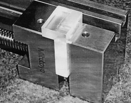
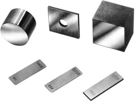
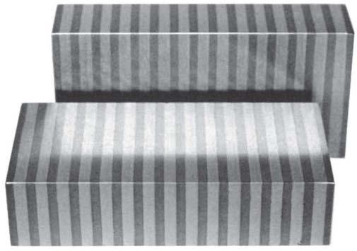
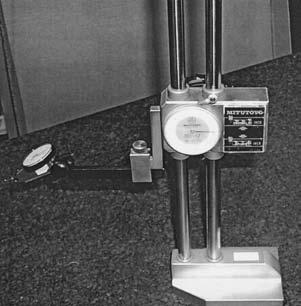
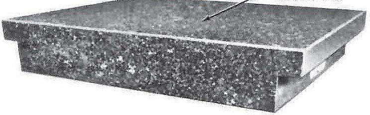
6 Setups include Surface Plates and Accessories Parallels Blocks Gage Blocks Knee Precision Vise Sine Plate Surface Gage Height Gage

7 Flatness Optimum plane setup Jack screws shown Once leveled, F.I.M.
 F.I.M.")
8 Flatness Fixed plane method Three Indian Pins (equal height) F.I.M.

9 Circularity (Roundness) V-Block Method Use correct V angle Rotate the part on itself Use the equation to correct the F.I.M. value V ANGLE = n Circularity Radial;.003 = = = FIM 1+ Csc A
 Put the diameter in the jaws Rotate the part for a F.")
10 Circularity (Roundness) Rotab Method Check jaw runout with a gage pin (10% Rule) Put the diameter in the jaws Rotate the part for a F.I.M.

 readings F.I.")
11 Straightness Surface Elements Each line element must be straight Jack screw setup levels the part at top-dead-center (each end) FIM using top-dead-center Zero Set (each end) readings

12 Straightness Surface Elements Each line element must be straight within.002" Measurement is a F.I.M. Two equal gage block stacks establish the optimum line Move in and sweep across another straight line

13 Parallelism Offset Datums Offset Multiple Datums Surface plate contacts A Gage block contacts B F.I.M. Measurement

14 Parallelism Multiple Datums Multiple datum Inspect the datum profile control first Surface plate contacts high points Surface plate simulates datum plane A F.I.M. Measurement
 Mount datums on blocks F.I.M. on the surface")
15 Parallelism Hidden Datums Datums are offset Two blocks (shown) (or twin parallels could be used) Mount datums on blocks F.I.M. on the surface


16 Parallelism of an Axis The axis must be parallel to datum A Using a slip-fit gage pin, measure the F.I.M. Zero Set Difference


17 Parallelism Axis to Axis Slip-fit pin in datum A Datum pin in the V-Block Zero at one end on top-deadcenter Setup See the difference at the other end Check other directions Zero Set Difference
 until")
18 Perpendicularity Only datum A is mounted F.I.M. is best fit Rotate part (clockwise / counter clockwise) until smallest F.I.M. is found

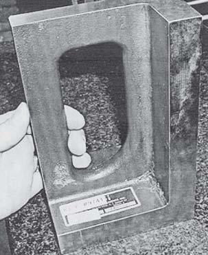
19 Perpendicularity Mount datum A Right angel plate aligns datum B F.I.M. across the entire surface Part is aligned, no manual alignment is necessary (or allowed)

20 Perpendicularity Surface to Axis V-notches in precision vise establish datum B Rotate the setup F.I.M. on the surface


21 Perpendicularity Slip-fit gage pin in the hole Part datum A mounted on a right angle plate Top-dead-center readings over the distance Check again in a different rotation Zero Set Difference


22 Perpendicularity Axis to Axis Slip-fit gage pin in datum A Datum pin mounted in V-Block V-Block setup rotated Find zero at top-dead-center on one end Measure the difference at the other end Zero Set Difference

23 Angularity A Sine Bar (shown) or Sine Plate Mount datum A on the Sine Bar Setup the angle using the sine of 30⁰ times the length of the bar F.I.M. across the entire surface Rotate and sweep for best fit F.I.M.

24 Circular Runout Tri-Roll (shown) or V-Block if necessary to mount and rotate the part on datum A F.I.M. at the surface of circular sections

25 Circular Runout Slip-fit gage pin simulates datum A Pin is resting in matched V s Part is rotated on the simulator F.I.M., at different circular sections, must be equal to or less than.001"

26 Circular Runout V-Block mounts datum A Dial indicator is placed at on circular section Part is rotated for F.I.M.

27 Circular Runout - Counterbore Datum A is pinned Pin is resting in the Tri-Roll Dial indicator is placed at one circular section Part is rotated for a F.I.M. Move to another circular section and repeat


28 Total Runout Datum mounted Indicator must traverse across One F.I.M. value for entire surface
 on")

29 Total Runout Datum is in the Tri-Roll Indicator (guided) on top-deadcenter (TDC) Indicator is traversed while part rotates TDC Traverse
 moved over to align with vertical crosshair Stage is then indexed away by the basic.")
30 Profile Datums - Comparator Contour profile with two datums Comparator stage moved up to align with horizontal crosshair Right angle plate (on the stage) moved over to align with vertical crosshair Stage is then indexed away by the basic.190 dimensions
31 Profile Datums - Comparator Overlay is placed on screen and lined up with crosshairs Part is mounted on stage and against right angle plate Index into zone This part is out, rejected

32 Profile - Coplanar Level three points on both surfaces using jack screws Once level, find the F.I.M over both surfaces


33 Profile - Coplanar Part datum is mounted in a setup Indicator is set at zero on the simulator Run indicator across the Zero surface for a This is not a F.I.M.
 Two opposing indicators Rotate the part to find E Very problematic")
34 Concentricity Differential measurements required to find axis eccentricity ( E ) Two opposing indicators Rotate the part to find E Very problematic measurement
 Centerplane cannot deviate from datum A more than.")
35 Symmetry Differential measurements Measure from both sides to find the centerplane symmetry error (E) Centerplane cannot deviate from datum A more than.002 in either direction M2 M1

36 Position Three Datums Mount datums A, B, and C using simulators Measure each coordinate and find the deviations Calculate the actual cylindrical zone Bonus tolerance may be available


37 Position - CMM Probe the simulators Mount datums Measure the coordinates Allow appropriate cylindrical zone (with bonus I/A)


38 Position Surface Plate Setup Mount datums against simulators Measure coordinates Calculate actual zones


39 Position Best Fit Lower frame inspection CMM Either CMM or a Surface Plate Setup Measure directly from axis to axis Best fit the data Surface Plate Measure
40 Position Best Fit Inspection is complete Data (deviations) recorded
41 Position Best Fit Lower frame inspection Paper gage shows that the part is acceptable (best fit)

42 Questions? Need Training?
GD&T - Profile Tolerancing
 GD&T - Profile Tolerancing PMPA Technical Conference Rapid Response to Make the Cut Grand Rapids, MI April 11, 2016 Gary K. Griffith Corona, California Gary K. Griffith 48 Years Exp. Technical Book Author
AC : TEACHING APPLIED MEASURING METHODS USING GD&T
 AC 2008-903: TEACHING APPLIED MEASURING METHODS USING GD&T Ramesh Narang, Indiana University-Purdue University-Fort Wayne RAMESH V. NARANG is an Associate Professor of Industrial Engineering Technology
Answers to Questions and Problems
 Fundamentals of Geometric Dimensioning and Tolerancing Using Critical Thinking Skills 3 rd Edition By Alex Krulikowski Answers to Questions and Problems Second Printing Product #: 1103 Price: $25.00 Copyright
GEOMETRIC DIMENSIONING AND TOLERANCING (GD&T)
") GEOMETRIC DIMENSIONING AND TOLERANCING (GD&T) Based on ASME Y14.5M-1994 Standard Duration : 4 days Time : 9:00am 5:00pm Methodology : Instructor led Presentation, exercises and discussion Target : Individuals
GEOMETRIC DIMENSIONING AND TOLERANCING (GD&T) Based on ASME Y14.5M-1994 Standard Duration : 4 days Time : 9:00am 5:00pm Methodology : Instructor led Presentation, exercises and discussion Target : Individuals
GEOMETRIC DIMENSIONING AND TOLERANCING (GD&T) Based on ASME Y14.5M-1994 Standard
 Based on ASME Y14.5M-1994 Standard") GEOMETRIC DIMENSIONING AND TOLERANCING (GD&T) Based on ASME Y14.5M-1994 Standard Duration: 4 Days Training Course Content: Day 1: Tolerancing in Engineering Drawing (9:00am-10:00am) 1.0 Geometric Dimensioning
GEOMETRIC DIMENSIONING AND TOLERANCING (GD&T) Based on ASME Y14.5M-1994 Standard Duration: 4 Days Training Course Content: Day 1: Tolerancing in Engineering Drawing (9:00am-10:00am) 1.0 Geometric Dimensioning
Geometric Dimensioning and Tolerancing
 Geometric Dimensioning and Tolerancing (Known as GDT) What is GDT Helps ensure interchangeability of parts. Use is dictated by function and relationship of the part feature. It does not take the place
INDEX. Datum feature symbol, 21
 INDEX Actual Mating Envelope, 11 Actual Minimum Material Envelope, 11 All Around, 149 ALL OVER, 157, 158,363 Allowed vs. actual deviations from true position, 82 Angularity, 136 axis, 140 line elements,
Test Answers and Exam Booklet. Geometric Tolerancing
 Test Answers and Exam Booklet Geometric Tolerancing iii Contents ANSWERS TO THE GEOMETRIC TOLERANCING TEST............. 1 Part 1. Questions Part 2. Calculations SAMPLE ANSWERS TO THE GEOMETRIC TOLERANCING
Workpiece drawing factors. Size Shape Composition Dimensions Specifications
 ITCD 301-001 Workpiece drawing factors Size Shape Composition Dimensions Specifications Tolerance Total amount of dimensional variation Designer specifies an unattainable condition Designer specifies a
ASME Y14.5M-1994 GD&T Certification Preparation Examination
 ASME Y14.5M-1994 GD&T Certification Preparation Examination Directions: On the response sheet on the last page, fill in the circle of the letter which best completes the following statements. Do not write
Geometric Tolerances & Dimensioning
 Geometric Tolerances & Dimensioning MANUFACTURING PROCESSES - 2, IE-352 Ahmed M. El-Sherbeeny, PhD KING SAUD UNIVERSITY Spring - 2015 1 Content Overview Form tolerances Orientation tolerances Location
Engineering & Design: Geometric Dimensioning
 Section Contents NADCA No. Format Page Frequently Asked Questions -2 s e c t i o n 1 Introduction -2 2 What is GD&T? -2 3 Why Should GD&T be Used? -2 4 Datum Reference Frame -4 4.1 Primary, Secondary,
Geometric Dimensioning & Tolerancing
 Western Technical College 31420350 Geometric Dimensioning & Tolerancing Course Outcome Summary Course Information Description Career Cluster Instructional Level Total Credits 1.00 Total Hours 36.00 Recognition
Geometric Dimensioning and Tolerancing
 Geometric dimensioning and tolerancing (GDT) is Geometric Dimensioning and Tolerancing o a method of defining parts based on how they function, using standard ASME/ANSI symbols; o a system of specifying
Terms The definitions of 16 critical terms defined by the 2009 standard 1
 856 SALT LAKE COURT SAN JOSE, CA 95133 (408) 251 5329 Terms The definitions of 16 critical terms defined by the 2009 standard 1 The names and definitions of many GD&T terms have very specific meanings.
A Concise Introduction to Engineering Graphics
 A Concise Introduction to Engineering Graphics Fourth Edition Including Worksheet Series A Timothy J. Sexton, Professor Department of Industrial Technology Ohio University BONUS Book on CD: TECHNICAL GRAPHICS
AC : CLARIFICATIONS OF RULE 2 IN TEACHING GEOMETRIC DIMENSIONING AND TOLERANCING
 AC 2007-337: CLARIFICATIONS OF RULE 2 IN TEACHING GEOMETRIC DIMENSIONING AND TOLERANCING Cheng Lin, Old Dominion University Alok Verma, Old Dominion University American Society for Engineering Education,
Representation of features Geometric tolerances. Prof Ahmed Kovacevic
 ME 1110 Engineering Practice 1 Engineering Drawing and Design - Lecture 6 Representation of features Geometric tolerances Prof Ahmed Kovacevic School of Engineering and Mathematical Sciences Room C130,
Geometric Tolerancing
 Geometric Tolerancing Distorted Objects by Suzy Lelievre Scale Transform SALOME Geometry User s Guide: Scale Transform Baek-Ki-Kim-Twisted Stool Mesh Geometric Tolerancing What is it? Geometric Tolerancing
GD&T Reckoner Course reference material for. A Web-based learning system from.
 GD&T Reckoner Course reference material for A Web-based learning system from This is not the complete document. Only Sample pages are included. The complete document is available to registered users of
Concentricity and Symmetry Controls
 Concentricity and Symmetry Controls Alessandro Anzalone, Ph.D. Hillsborough Community College, Brandon Campus Concentricity and Symmetry Controls Sections: 1. Concentricity Control 2. Symmetry Control
A R C H I V E
 A R C H I V E 2 0 0 6 Tutorial Geometric Dimensioning And Tolerancing: A Primer For The BiTS Professional Thomas Allsup Manager of Technology Anida Technologies COPYRIGHT NOTICE The papers in this publication
FOREWORD. Technical product documentation using ISO GPS - ASME GD&T standards
 Technical product documentation using ISO GPS - ASME GD&T standards FOREWORD Designers create perfect and ideal geometries through drawings or by means of Computer Aided Design systems, but unfortunately
To help understand the 3D annotations, the book includes a complete tutorial on SOLIDWORKS MBD
 To help understand the 3D annotations, the book includes a complete tutorial on SOLIDWORKS MBD Technical product documentation using ISO GPS - ASME GD&T standards FOREWORD Designers create perfect and
Geometric Boundaries
 Geometric Boundaries Interpretation and Application of Geometric Dimensioning and Tolerancing (Using the Customary Inch System) Based on ASME Y14.5M-1994 Written and Illustrated by Kelly L. Bramble Published
ME 114 Engineering Drawing II
 ME 114 Engineering Drawing II FITS, TOLERANCES and SURFACE QUALITY MARKS Mechanical Engineering University of Gaziantep Dr. A. Tolga Bozdana Assistant Professor Tolerancing Tolerances are used to control
Geometric Boundaries II
 Geometric Boundaries II Interpretation and Application of Geometric Dimensioning and Tolerancing (Using the Inch and Metric Units) Based on ASME Y14.5-2009 (R2004) Written and Illustrated by Kelly L. Bramble
A study of accuracy of finished test piece on multi-tasking machine tool
 A study of accuracy of finished test piece on multi-tasking machine tool M. Saito 1, Y. Ihara 1, K. Shimojima 2 1 Osaka Institute of Technology, Japan 2 Okinawa National College of Technology, Japan yukitoshi.ihara@oit.ac.jp
Measurement and Tolerances
 Measurement and Tolerances Alessandro Anzalone, Ph.D. Hillsborough Community College, Brandon Campus Measurement and Tolerances Sections: 1. Meaning of Tolerance 2. Geometric Dimensioning and Tolerancing
MACHINE TOOL ALIGNMENT TESTS
 MACHINE TOOL ALIGNMENT TESTS 39 MACHINE TOOL TESTING INTRODUCTION: The surface components produced by machining processes are mostly by generation. As a result, the quality of surface produced depends
Dimensioning. Dimensions: Are required on detail drawings. Provide the shape, size and location description: ASME Dimensioning Standards
 Dimensioning Dimensions: Are required on detail drawings. Provide the shape, size and location description: - Size dimensions - Location dimensions - Notes Local notes (specific notes) General notes ASME
Virtual CAD Parts to Enhance Learning of Geometric Dimensioning and Tolerancing. Lawrence E. Carlson University of Colorado at Boulder
 Virtual CAD Parts to Enhance Learning of Geometric Dimensioning and Tolerancing Lawrence E. Carlson University of Colorado at Boulder Introduction Geometric dimensioning and tolerancing (GD&T) is an important
GEOMETRICAL TOLERANCING
 GEOMETRICAL TOLERANCING Introduction In a typical engineering design and production environment, the designer of a part rarely follows the design to the shop floor, and consequently the only means of communication
FACULTY OF ENGINEERING DESIGN AND PRODUCTION ENGINEERING DEPARTMENT. Credit Hour System Metrology Lab 1 MDP 240. Sine Bars. Metrology laboratory
 FACULTY OF ENGINEERING DESIGN AND PRODUCTION ENGINEERING DEPARTMENT Report On: Credit Hour System Metrology Lab 1 MDP 240 (13) Sine Bars Metrology laboratory Class No: B.N. Student Name Remark Signature
Module-4 Lecture-2 Perpendicularity measurement. (Refer Slide Time: 00:13)
") Metrology Prof. Dr. Kanakuppi Sadashivappa Department of Industrial and Production Engineering Bapuji Institute of Engineering and Technology-Davangere Module-4 Lecture-2 Perpendicularity measurement (Refer
Metrology Prof. Dr. Kanakuppi Sadashivappa Department of Industrial and Production Engineering Bapuji Institute of Engineering and Technology-Davangere Module-4 Lecture-2 Perpendicularity measurement (Refer
ME 410 Mechanical Engineering Systems Laboratory
 ME 410 Mechanical Engineering Systems Laboratory Laboratory Lecture 1 GEOMETRIC TOLERANCING & SOURCES OF ERRORS Geometric dimensioning and tolerancing (GD&T) is a symbolic language used on engineering
COMMON SYMBOLS/ ISO SYMBOL ASME Y14.5M ISO FEATURE CONTROL FRAME DIAMETER/ SPHERICAL DIAMETER/ AT MAXIMUM MATERIAL CONDITION
 1 82 COMMON SYMBOLS/ Shown below are the most common symbols that are used with geometric tolerancing and other related dimensional requirements on engineering drawings. Note the comparison with the ISO
Introduction. Objectives
 Introduction As more and more manufacturers become immersed in the global economy, standardization plays a critical role in their success. Geometric dimensioning and tolerancing (GD&T) provides a set of
A Strategy for Tolerancing a Part 1
 856 SLT LKE OURT SN JOSE, 95133 (408) 251 5329 Strategy for Tolerancing a Part 1 The first step in tolerancing a feature of size, such as the hole in Figure 14-1, is to specify the size and size tolerance
Product and Manufacturing Information (PMI)
") Product and Manufacturing Information (PMI) 1 Yadav Virendrasingh Sureshnarayan, 2 R.K.Agrawal 1 Student of ME in Product Design and Development,YTCEM -Bhivpuri road-karjat, Maharastra 2 HOD Mechanical
Product and Manufacturing Information (PMI) 1 Yadav Virendrasingh Sureshnarayan, 2 R.K.Agrawal 1 Student of ME in Product Design and Development,YTCEM -Bhivpuri road-karjat, Maharastra 2 HOD Mechanical
6/23/2016 Copyright 2016 Society of Manufacturing Engineers
 6/23/2016 Copyright 2016 Society of Manufacturing Engineers --- 1 --- GEOMETRIC DIMENSIONING & TOLERANCING FUNDAMENTALS Form Controls & Datums - GDT2 TRT: 25:44 Minutes SCENE 1. GDT01A, CGS: FBI warning
David A. Madsen. Faculty Emeritus
 i Q eometric ' ' Dimensioning andtolerancing Ninth Edition Based on ASME Y14.5-2009 AWk A ejacy ofjejtccftence APPROVED PUBLICATION by David A. Madsen President, Madsen Designs Inc. www.madsendesigns.com
INSTITUTE OF AERONAUTICAL ENGINEERING (Autonomous) Dundigal, Hyderabad
 Dundigal, Hyderabad") Name Code INSTITUTE OF AERONAUTICAL ENGINEERING (Autonomous) Dundigal, Hyderabad -500 043 MECHANICAL ENGINEERING TUTORIAL QUESTION BANK : ENGINEERING METROLOGY : A50318 Class : III B.Tech I Semester Branch
Name Code INSTITUTE OF AERONAUTICAL ENGINEERING (Autonomous) Dundigal, Hyderabad -500 043 MECHANICAL ENGINEERING TUTORIAL QUESTION BANK : ENGINEERING METROLOGY : A50318 Class : III B.Tech I Semester Branch
Chapter 22 MACHINING OPERATIONS AND MACHINE TOOLS
 Chapter 22 MACHINING OPERATIONS AND MACHINE TOOLS Turning and Related Operations Drilling and Related Operations Milling Machining Centers and Turning Centers Other Machining Operations High Speed Machining
AutoCAD and Its Applications BASICS Reference Material. Drafting Symbols
 AutoCAD and Its Applications BASICS Reference Material Drafting Symbols Symbols provide a common language for drafters all over the world. owever, symbols are meaningful only if they are drawn according
SPECIFICATION
 Rev. R SPECIFICATION 9-3800 Page 1 of 26 Amphenol Corporation Sidney, New York U TITLE STANDARD SPECIAL USE DESCRIPTION ENGINEERING DRAWING Revisions REV. LETTER ISSUE NUMBER ORIGINATOR DATE APPROVAL M
Name: Machine Tool Technology ( )
") Name: Machine Tool Technology (58.0501) Directions: Evaluate the student by checking the appropriate number to indicate the degree of competency. Rating Scale (0-6): 0 No Exposure no experience/knowledge
Name: Machine Tool Technology (58.0501) Directions: Evaluate the student by checking the appropriate number to indicate the degree of competency. Rating Scale (0-6): 0 No Exposure no experience/knowledge
Rotational Patterns of Pick and Place Features
 Rotational Patterns of Pick and Place Features The most efficient way to create multiple copies of one feature is to use the patterning function. Not only is it faster, but dimensioning is simplified,
AC : CALCULATION OF TOLERANCE STACKS USING DIRECT-POSITION APPROACH IN GEOMETRIC DIMENSIONING AND TOLERANCING
 AC 2009-138: CALCULATION OF TOLERANCE STACKS USING DIRECT-POSITION APPROACH IN GEOMETRIC DIMENSIONING AND TOLERANCING Cheng Lin, Old Dominion University American Society for Engineering Education, 2009
Alessandro Anzalone, Ph.D. Hillsborough Community College, Brandon Campus
 Alessandro Anzalone, Ph.D. Hillsborough Community College, Brandon Campus Sections: 1. Definitions 2. Material Conditions 3. Modifiers 4. Radius and Controlled Radius 5. Introduction to Geometric Tolerances
Product and Manufacturing Information(PMI)
") Product and Manufacturing Information(PMI) Ravi Krishnan V 1 Post Graduate Student Department of Mechanical Engineering Veermata Jijabai Technological Institute Mumbai, India ravi.krishnan30@gmail.com
Product and Manufacturing Information(PMI) Ravi Krishnan V 1 Post Graduate Student Department of Mechanical Engineering Veermata Jijabai Technological Institute Mumbai, India ravi.krishnan30@gmail.com
Metrology and instrumentation Indian Institute of Technology
 Metrology and instrumentation Indian Institute of Technology SOURCE: S. KALPAKJIAN BOOK SLIDE-WAY CROSS-SECTION Cross-section of a machine tool slide-way. The width, depth, angles, and other dimensions
Rotational Patterns of Sketched Features Using Datum Planes On-The-Fly
 Rotational Patterns of Sketched Features Using Datum Planes On-The-Fly Patterning a sketched feature (such as a slot, rib, square, etc.,) requires a slightly different technique. Why can t we create a
Improving Manufacturability
 Improving Manufacturability GD&T is a Tool Not a Weapon Joe Soistman Quality Manufacturing Solutions, LLC Overview What is manufacturability, and why is it important? Overview What is manufacturability,
DRAFTING MANUAL. Dimensioning and Tolerancing Rules
 Page 1 1.0 General This section is in accordance with ASME Y14.5-2009 Dimensioning and Tolerancing. Note that Rule #1 is the only rule that is numbered in the 2009 standard. All of the other rules fall
Technical drawings and their interpreta1on. ME Fall 2011 Eradat SJSU Based on notes on Jim Burge and other online resources
 Technical drawings and their interpreta1on ME 297-1 Fall 2011 Eradat SJSU Based on notes on Jim Burge and other online resources Technical drawings Technical drawings Orthographic projec1on Isometric layout
Introduction to GD&T Session 2: Rules and Concepts of GD&T
 Introduction to GD&T Session 2: Rules and Concepts of GD&T An exploration of the language known as Geometric Dimensioning and Tolerancing Instructor: John-Paul Belanger Review Benefits of GD&T The GD&T
DIMENSIONING ENGINEERING DRAWINGS
 DIMENSIONING ENGINEERING DRAWINGS An engineering drawing must be properly dimensioned in order to convey the designer s intent to the end user. Dimensions provide the information needed to specify the
Datum reference frame Position and shape tolerances Tolerance analysis
 Datum reference frame Position and shape tolerances Tolerance analysis Šimon Kovář Datum reference frame Datum reference frames are typically for 3D. A typical datum reference frame is made up of three
the same information given in two different 1. Dimensions should NOT be duplicated, or Dimension Guidelines Incorrect ways.
 Dimension Guidelines 1. Dimensions should NOT be duplicated, or the same information given in two different ways. Incorrect 1. Dimensions should NOT be duplicated, or the same information given in two
Pattern Inspection with Variable Geometric Tolerance Limits
 Pattern Inspection with Variable Geometric Limits From Disregarding to Fully Applying Variable Feature Bonus and Datum Shift s in a Pattern Inspection By Paul F. Jackson Variable Limit Specifications and
Advanced Dimensional Management LLC
 Index: Mechanical Tolerance Stackup and Analysis Bryan R. Fischer Accuracy and precision 8-9 Advanced Dimensional Management 14, 21, 78, 118, 208, 251, 286, 329-366 Ambiguity 4, 8-14 ASME B89 48 ASME Y14.5M-1994
ENVELOPE REQUIREMENT VERSUS PRINCIPLE OF INDEPENDENCY
 ENVELOPE REQUIREMENT VERSUS PRINCIPLE OF INDEPENDENCY Carmen SIMION, Ioan BONDREA University "Lucian Blaga" of Sibiu, Faculty of Engineering Hermann Oberth, e-mail:carmen.simion@ulbsibiu.ro, ioan.bondrea@ulbsibiu.ro
SALE SALE SALE palmgren.com chhanson.com SWIVEL BASES SPEED HANDLES
 FRIENDS OF PALMGREN SPECIAL OFFERS WORKHOLDING S EVENT DUAL FORCE PRECISION MACHINE VISES Palmgren s Dual Force line of machine vises are all designed for precision part clamping and are ideal for use
ANSI ORIFICE FLANGES METAL-KOREA
 METAL-KOREA ANSI ORIFICE FLANGES ORIFICE FLANGES are widely used in conjunction with orifice meters for measuring the rate of flow of liquids and gases. They are basically the same as standard welding
Ramesh H. Aralaguppi 1, T. Subramanian 2
 Study of Spindle Rotational Accuracies versus Bore Accuracies on Machined Test Pieces on a CNC Machining Center Ramesh H. Aralaguppi 1, T. Subramanian 2 Abstract Metal Cutting Machine tools are built to
Ahsanullah University of Science and Technology (AUST) Department of Mechanical and Production Engineering
 Department of Mechanical and Production Engineering") Ahsanullah University of Science and Technology (AUST) Department of Mechanical and Production Engineering LABORATORY MANUAL For the students of Department of Mechanical and Production Engineering 1 st
Ahsanullah University of Science and Technology (AUST) Department of Mechanical and Production Engineering LABORATORY MANUAL For the students of Department of Mechanical and Production Engineering 1 st
JOB QUALIFICATION STANDARD (JQS)
") Occupation: Work Process: Maintenance Mechanic Machine Shop Practical Hours: 250 hrs. JOB QUALIFICATION STANDARD (JQS) DOL Standard: Manual Machining Fundamentals: Apply a working knowledge of metal removal
Occupation: Work Process: Maintenance Mechanic Machine Shop Practical Hours: 250 hrs. JOB QUALIFICATION STANDARD (JQS) DOL Standard: Manual Machining Fundamentals: Apply a working knowledge of metal removal
Tool and Die Maker Level 2
 Level 2 B2 Read and Interpret Drawings II Duration: 32 hours 32 hours 0 hours This unit of instruction introduces the Tool and Die Maker Apprentice with the knowledge and skills necessary to read and interpret
Contents. Notes on the use of this publication
 Contents Preface xxiii Scope Notes on the use of this publication xxv xxvi 1 Layout of drawings 1 1.1 General 1 1.2 Drawing sheets 1 1.3 Title block 2 1.4 Borders and frames 2 1.5 Drawing formats 2 1.6
Catalog No. E Perfectly formed for production, quality control rooms and laboratories form measuring instruments from Mitutoyo
 FORM MEASUREMENT Catalog No. E4261-211 Perfectly formed for production, quality control rooms and laboratories form measuring instruments from Mitutoyo You define the task... ROUNDTE Measuring technology
125 years of innovation. Cylindricity. Global Excellence in Metrology
 125 years of innovation Cylindricity Cylindricity Contents Introduction Instrument Requirements Reference Cylinders Cylindricity Parameters Measurement Techniques & Methods Measurement Errors & Effects
Fast Optical Form Measurements of Rough Cylindrical and Conical Surfaces in Diesel Fuel Injection Components
 Fast Optical Form Measurements of Rough Cylindrical and Conical Surfaces in Diesel Fuel Injection Components Thomas J. Dunn, Robert Michaels, Simon Lee, Mark Tronolone, and Andrew Kulawiec; Corning Tropel
MACHINE TOOL ACCESSORIES
 VERTICAL 5-C COLLET VISE SERIES 344: VERTICAL 3-C COLLET VISE SERIES 344: : 2-1/2 x 7-3/4 Height: 4 Small movement of lever opens or closes collet. 2030000 CAM OPERATED 5-C HORIZONTAL/VERTICAL COLLET FIXTURE
PolyWorks Inspector Standard. 3 Day Course
 PolyWorks Inspector Standard INTRODUCTION TO POLYWORKS Workspace Manager Basic Options File and Project Structures PolyWorks License Manager INTRODUCTION TO POLYWORKS INSPECTOR User Interface Basic Options
SCOPE OF ACCREDITATION TO ISO/IEC 17025:2005 & ANSI/NCSL Z & ANSI/NCSL Z
 SCOPE OF ACCREDITATION TO ISO/IEC 17025:2005 & ANSI/NCSL Z540-1-1994 & ANSI/NCSL Z540.3-2006 MITUTOYO AMERICA CORPORATION 965 Corporate Blvd Aurora, IL 60502 Amosh Kumar Phone: 888 648 8869 CALIBRATION
Spatial Demonstration Tools for Teaching Geometric Dimensioning and Tolerancing (GD&T) to First-Year Undergraduate Engineering Students
 to First-Year Undergraduate Engineering Students") Paper ID #17885 Spatial Demonstration Tools for Teaching Geometric Dimensioning and Tolerancing (GD&T) to First-Year Undergraduate Engineering Students Miss Myela A. Paige, Georgia Institute of Technology
Paper ID #17885 Spatial Demonstration Tools for Teaching Geometric Dimensioning and Tolerancing (GD&T) to First-Year Undergraduate Engineering Students Miss Myela A. Paige, Georgia Institute of Technology
Study of Vee Plate Manufacturing Method for Indexing Table
 Study of Vee Plate Manufacturing Method for Indexing Table Yeon Taek OH Department of Robot System Engineering, Tongmyong University 428 Sinseon-ro, Nam-gu, Busan, Korea yeonoh@tu.ac.kr Abstract The indexing
The Author. 1 st Edition 2008 Self-published by Frenco GmbH
 The Author Graduate Engineer (Dipl. Ing., FH) Rudolf Och was born in Bamberg, Germany in 1951. After graduating in mechanical engineering he founded FRENCO GmbH in Nuremberg, Germany in 1978. In the beginning,
Injection Molding. System Recommendations
 Bore Application Alignment Notes Injection Molding System Recommendations L-743 Injection Molding Machine Laser The L-743 Ultra-Precision Triple Scan Laser is the ideal instrument to quickly and accurately
COURSE SYLLABUS. Course Title: Introduction to Quality and Continuous Improvement
 COURSE SYLLABUS Course Number: TBD Course Title: Introduction to Quality and Continuous Improvement Course Pre-requisites: None Course Credit Hours: 3 credit hours Structure of Course: 45/0/0/0 Textbook:
Quality Procedure QP159 General Requirements for Machined Parts
 1. PURPOSE 1.1. This procedure provides general product fabrication requirements. It also provides interpretation of certain requirements specified on product drawings, models, and electronic files. 2.
Turning and Lathe Basics
 Training Objectives After watching the video and reviewing this printed material, the viewer will gain knowledge and understanding of lathe principles and be able to identify the basic tools and techniques
Processing and Quality Assurance Equipment
 Processing and Quality Assurance Equipment The machine tool, the wash station, and the coordinate measuring machine (CMM) are the principal processing equipment. These machines provide the essential capability
Elementary Dimensioning
 Elementary Dimensioning Standards Institutions ANSI - American National Standards Institute - creates the engineering standards for North America. ISO - International Organization for Standardization -
Trade of Toolmaking. Module 3: Milling Unit 6: Angle Slotting & Reaming Phase 2. Published by. Trade of Toolmaking Phase 2 Module 3 Unit 6
 Trade of Toolmaking Module 3: Milling Unit 6: Angle Slotting & Reaming Phase 2 Published by SOLAS 2014 Unit 6 1 Table of Contents Document Release History... 3 Unit Objective... 4 Introduction... 4 1.0
MACHINE TOOLS GRINDING MACHINE TOOLS
 MACHINE TOOLS GRINDING MACHINE TOOLS GRINDING MACHINE TOOLS Grinding in generally considered a finishing operation. It removes metal comparatively in smaller volume. The material is removed in the form
MACHINIST TECHNICIAN - LATHE (582)
") DESCRIPTION Students will demonstrate technical knowledge and skills to plan, manufacture, assemble, test products, and modify metal parts using machine shop and CNC processes in support of other manufacturing,
DESCRIPTION Students will demonstrate technical knowledge and skills to plan, manufacture, assemble, test products, and modify metal parts using machine shop and CNC processes in support of other manufacturing,
GAGING AND INSPECTION
 Fixture Plates...75 Fixturing Towers...76 CMM Fixturing Kits... 77-78 Clamping Components... 79-80 Standoffs and Locators... 81-82 Magnetic Components... 83-84 Height Adjustment...84 Positioners...85 Clamp
ORTHOGRAPHIC PROJECTIONS. Ms. Sicola
 ORTHOGRAPHIC PROJECTIONS Ms. Sicola Objectives List the six principal views of projection Sketch the top, front and right-side views of an object with normal, inclined, and oblique surfaces Objectives
ROOP LAL Unit-6 Lathe (Turning) Mechanical Engineering Department
 Mechanical Engineering Department") Notes: Lathe (Turning) Basic Mechanical Engineering (Part B) 1 Introduction: In previous Lecture 2, we have seen that with the help of forging and casting processes, we can manufacture machine parts of
Notes: Lathe (Turning) Basic Mechanical Engineering (Part B) 1 Introduction: In previous Lecture 2, we have seen that with the help of forging and casting processes, we can manufacture machine parts of
ME Week 2 Project 2 Flange Manifold Part
 1 Project 2 - Flange Manifold Part 1.1 Instructions This project focuses on additional sketching methods and sketching commands. Revolve and Work features are also introduced. The part being modeled is
Module-2 Lecture-1 Angle plate, steel rule, spring calipers. (Refer Slide Time: 00:14)
") Metrology Prof. Dr. Kanakuppi Sadashivappa Department of Industrial and Production Engineering Bapuji Institute of Engineering and Technology-Davangere Module-2 Lecture-1 Angle plate, steel rule, spring
Metrology Prof. Dr. Kanakuppi Sadashivappa Department of Industrial and Production Engineering Bapuji Institute of Engineering and Technology-Davangere Module-2 Lecture-1 Angle plate, steel rule, spring
Delrin Cone T-Handle Spring Stop w/pad...9 Screw Jack Large Toggle Clamp w/pad...9 Adjustable Ball Positioner...14
 Distributed by Rapp Industrial Sales INDEX Aluminum Fixture Plates...4 Pin Rest...11 Acrylic Plates...4 Thread Adapter...11 Fixturing Towers...5 Delrin Cone...11 CMM Fixturing Kits...6-7 Magnetic Rest
Chapter 2: Dimensioning Basic Topics Advanced Topics Exercises
 Chapter 2: Dimensioning Basic Topics Advanced Topics Exercises Dimensioning: Basic Topics Summary 2-1) Detailed Drawings 2-2) Learning to Dimension 2-3) Dimension Appearance and Techniques. 2-4) Dimensioning
Machinist--Cert Students apply industry standard safety practices and specific safety requirements for different machining operations.
 MTT Date: 09/13/2018 TECHNOLOGY MTT Machine Tool Technology--AA Students apply industry standard safety practices and specific safety requirements for different machining operations. Students calculate
Competency, knowledge and skill areas often offer varying definitions. For purposes of this toolkit, NIMS defines them in the following manner:
 Toolkit Roadmap Title of report Credential name Narrative description of credential DEFINITION OF TERMS Competency, knowledge and skill areas often offer varying definitions. For purposes of this toolkit,
45 CUTTING HEAD TILE SAW-BLADE ALIGNMENT PROCEDURE
 The of the MK-770 may become misaligned with the Cutting Head of the Tile Saw over time. Should misalignment occur, perform the following steps to realign the Tile Saw. NOTE: If alignment problems are
9000 Level. DS-703 Page 1 of 22 3 TITLE WORK INSTRUCTIONS, GENERAL PRINT AMENDMENT
 evel DS-70 Page 1 of 22 TITE WORK INSTRUCTIONS, GENERA PRINT AMENDMENT Revision EXPANATION OF CHANGE Approvals DATE A Initial Release WB, GR 2/26/99 B C D E F G Add PMR caveat WB, GR 5/1/99 Add Surface
Geometric elements for tolerance definition in feature-based product models
 Loughborough University Institutional Repository Geometric elements for tolerance definition in feature-based product models This item was submitted to Loughborough University's Institutional Repository