Technical drawings and their interpreta1on. ME Fall 2011 Eradat SJSU Based on notes on Jim Burge and other online resources
|
|
|
- Carol Owen
- 5 years ago
- Views:
Transcription
1 Technical drawings and their interpreta1on ME Fall 2011 Eradat SJSU Based on notes on Jim Burge and other online resources
2 Technical drawings
3 Technical drawings Orthographic projec1on Isometric layout Dimensioning Tolerancing
4 Orthographic vs. isometric drawings hip://webtools.delmarlearning.com/sample_chapters/ _ch07.pdf
5 Orthographic projec1ons A method of projec1on in which an object is depicted (or a surface is mapped) using parallel lines to project its shape onto a plane.

6 Isometric drawings All isometric sketches start by construc1ng the isometric axes, which includes a ver1cal line for height and isometric lines to the ley and right, at angle angle of 30 from the horizon, for width and depth. The three faces seen in the isometric view are the same faces that would be seen in the normal orthographic views: top, front, and side
7 Inclined surfaces in isometric drawings Many objects have inclined surfaces that are represented by sloping lines in orthographic views. In isometric drawings, sloping surfaces appear as non- isometric lines. To create them, their endpoints, which are found on the ends of isometric lines, are joined with a straight line.

8 Basic steps for isometric drawing Isometric grid
9 Cylinders in isometric drawings
10 Bird s eye vie vs. worm s eye view

11 Crea1ng an orthographic drawing from isometric view
12

13 Inclined planes

14 Missing lines
15 Holes and cylinders
16 Concentric cylinders

17 Auxiliary views
18 Auxiliary views

19 Full sec1on view vs. standard orthographic view

20 Half sec1on view
21 Types of projec1on systems for 3D pictorial drawings Axonometric pictorials formed by parallel projectors that are perpendicular to the picture plane Obliques are formed by parallel projectors that are oblique to the picture plane Perspec1ves are formed by converging projectors that make varying angles with the picture plane

22 Pictorial 3D drawings
23 Geometric dimensioning and tolerancing (GD&T) is a system for defining and communica1ng engineering tolerances. It uses a symbolic language on engineering drawings and computer- generated three- dimensional solid models for explicitly describing nominal geometry and its allowable varia1on. It tells the manufacturing staff and machines what degree of accuracy and precision is needed on each facet of the part?
24 Linear dimensions
25 Angular dimensions
26 Grouping of dimensions
27 Applica1on and spacing of dimensions
28 Staggered dimensions
29 Leaders Leaders used to indicate where dimensions or notes are intended to apply. Leaders should be thin full lines, termina1ng in arrowheads or dots. Arrowheads always should terminate on a line Dots should be within the outline of the object. The use of long leaders should be avoided.
30 Leaders and minimizing them
31 Diameters, radii
32 Tabular dimensions
33 Tabular dimensions
34 Tolerances

35 Default tolerance (men1oned on 1tle box)
36 Datum In engineering and draying, a datum is a reference point, surface, or axis on an object against which measurements are made.
37 Datum symbols
38 Datum reference frame
39 Reference to Datum

40 Modifying symbol
41 Maximum Material CondiAon (MMC) & Least Material CondiAon (LMC) When a part feature contains the maximum amount of material allowed within the specified size limits, it's said to be in its maximum material condi1on. When a part feature contains the least amount of material allowed within the specified size limits, it's said to be in its least material condi6on. The material condi6on of the part is significant in geometric dimensioning and tolerancing.
42 Example for MMC & LMC An external feature, such as a fastener, is in its maximum material condi1on when it's at its upper size limit. EXAMPLE: The MMC of this fastener is.747. An internal feature, such as a hole, is in its maximum material condi6on when it's at its lower size limit. EXAMPLE: The MMC of this hole is EXAMPLE: The fastener is in its least material condi6on when it's at its lower size limit of.744. The hole is in its least material condi6on when it's at its upper size limit of.753.
43 Types of fit: Clearance fit When the specified size limits of ma1ng part features always result in clearance at assembly, the parts are said to have a clearance fit. EXAMPLE: In this drawing, even when the fastener is at its MMC size of. 747 and the hole is at its MMC size of.750, there is clearance
44 Types of fit: Interference fit When the specified size limits always produce interference at assembly, ma6ng part features are said to have an interference fit. EXAMPLE: In the center drawing, even when the fastener is at its LMC size of.5012 and the hole is at its LMC size of.5007, there is interference.
45 Types of fit: Transi1on fit When ma6ng part features do not fit together in their maximum material condi:on, but do fit at some point as they approach their least material condi:on, they are said to have a transi6on fit. EXAMPLE: In the drawing on the right, when the fastener is at its maximum material condi6on size of.5003, it will not fit the hole at its MMC size of However, when both features are manufactured at their least material condi6on size, they will fit together.

46 Geometric characteris1c symbol
47 Defini1on of cylindrical OD (outside diameter) Datum
48 Defini1on of cylindrical ID (inside diameter) datum
49 Concentricity
50 Circularity
51 Cylindricity
52 Surface flatness
53 Surface parallelism
54 Surface parallelism
55 Perpendicularity
56 Perpendicularity
57 Parallelism for axis
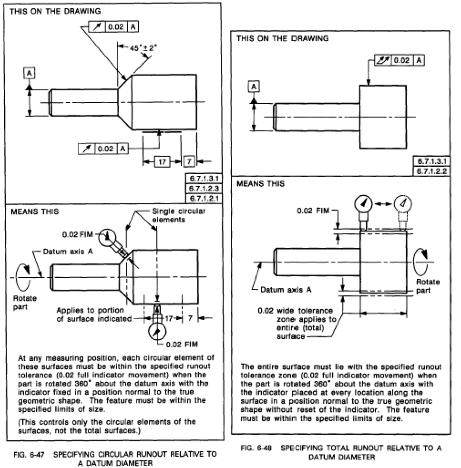
58 Runout
59 Surface orienta1on
60 Profile tolerance
61 Use of feature control frames
62 Basic dimensions
63 Geometric dimensioning & tolerancing Meaning of basic tolerances
64 Tolerancing using basic dimensions
65 Example of mul1ple features
66 Tolerance Zones
A Concise Introduction to Engineering Graphics
 A Concise Introduction to Engineering Graphics Fourth Edition Including Worksheet Series A Timothy J. Sexton, Professor Department of Industrial Technology Ohio University BONUS Book on CD: TECHNICAL GRAPHICS
GEOMETRIC DIMENSIONING AND TOLERANCING (GD&T) Based on ASME Y14.5M-1994 Standard
 Based on ASME Y14.5M-1994 Standard") GEOMETRIC DIMENSIONING AND TOLERANCING (GD&T) Based on ASME Y14.5M-1994 Standard Duration: 4 Days Training Course Content: Day 1: Tolerancing in Engineering Drawing (9:00am-10:00am) 1.0 Geometric Dimensioning
GEOMETRIC DIMENSIONING AND TOLERANCING (GD&T) Based on ASME Y14.5M-1994 Standard Duration: 4 Days Training Course Content: Day 1: Tolerancing in Engineering Drawing (9:00am-10:00am) 1.0 Geometric Dimensioning
Geometric Tolerances & Dimensioning
 Geometric Tolerances & Dimensioning MANUFACTURING PROCESSES - 2, IE-352 Ahmed M. El-Sherbeeny, PhD KING SAUD UNIVERSITY Spring - 2015 1 Content Overview Form tolerances Orientation tolerances Location
GEOMETRIC DIMENSIONING AND TOLERANCING (GD&T)
") GEOMETRIC DIMENSIONING AND TOLERANCING (GD&T) Based on ASME Y14.5M-1994 Standard Duration : 4 days Time : 9:00am 5:00pm Methodology : Instructor led Presentation, exercises and discussion Target : Individuals
GEOMETRIC DIMENSIONING AND TOLERANCING (GD&T) Based on ASME Y14.5M-1994 Standard Duration : 4 days Time : 9:00am 5:00pm Methodology : Instructor led Presentation, exercises and discussion Target : Individuals
Test Answers and Exam Booklet. Geometric Tolerancing
 Test Answers and Exam Booklet Geometric Tolerancing iii Contents ANSWERS TO THE GEOMETRIC TOLERANCING TEST............. 1 Part 1. Questions Part 2. Calculations SAMPLE ANSWERS TO THE GEOMETRIC TOLERANCING
GD&T Reckoner Course reference material for. A Web-based learning system from.
 GD&T Reckoner Course reference material for A Web-based learning system from This is not the complete document. Only Sample pages are included. The complete document is available to registered users of
ME 114 Engineering Drawing II
 ME 114 Engineering Drawing II FITS, TOLERANCES and SURFACE QUALITY MARKS Mechanical Engineering University of Gaziantep Dr. A. Tolga Bozdana Assistant Professor Tolerancing Tolerances are used to control
AC : CLARIFICATIONS OF RULE 2 IN TEACHING GEOMETRIC DIMENSIONING AND TOLERANCING
 AC 2007-337: CLARIFICATIONS OF RULE 2 IN TEACHING GEOMETRIC DIMENSIONING AND TOLERANCING Cheng Lin, Old Dominion University Alok Verma, Old Dominion University American Society for Engineering Education,
ME 410 Mechanical Engineering Systems Laboratory
 ME 410 Mechanical Engineering Systems Laboratory Laboratory Lecture 1 GEOMETRIC TOLERANCING & SOURCES OF ERRORS Geometric dimensioning and tolerancing (GD&T) is a symbolic language used on engineering
ASME Y14.5M-1994 GD&T Certification Preparation Examination
 ASME Y14.5M-1994 GD&T Certification Preparation Examination Directions: On the response sheet on the last page, fill in the circle of the letter which best completes the following statements. Do not write
Geometric Dimensioning and Tolerancing
 Geometric dimensioning and tolerancing (GDT) is Geometric Dimensioning and Tolerancing o a method of defining parts based on how they function, using standard ASME/ANSI symbols; o a system of specifying
Geometric Dimensioning and Tolerancing
 Geometric Dimensioning and Tolerancing (Known as GDT) What is GDT Helps ensure interchangeability of parts. Use is dictated by function and relationship of the part feature. It does not take the place
Mechanical Drawing. Unit 2 Study Guide for Chapters 6-10
 Mechanical Drawing Unit 2 Study Guide for Chapters 6-10 Chapter 6 Multiview Drawing Section 6.1 Understanding Orthographic Projection A. Technical Drawing: How can a technical drawing give more accurate
Contents. Notes on the use of this publication
 Contents Preface xxiii Scope Notes on the use of this publication xxv xxvi 1 Layout of drawings 1 1.1 General 1 1.2 Drawing sheets 1 1.3 Title block 2 1.4 Borders and frames 2 1.5 Drawing formats 2 1.6
ENGINEERING GRAPHICS 1E9
 Lecture 3 Monday, 15 December 2014 1 ENGINEERING GRAPHICS 1E9 Lecture 3: Isometric Projections Lecture 3 Monday, 15 December 2014 2 What is ISOMETRIC? It is a method of producing pictorial view of an object
Answers to Questions and Problems
 Fundamentals of Geometric Dimensioning and Tolerancing Using Critical Thinking Skills 3 rd Edition By Alex Krulikowski Answers to Questions and Problems Second Printing Product #: 1103 Price: $25.00 Copyright
Alessandro Anzalone, Ph.D. Hillsborough Community College, Brandon Campus
 Alessandro Anzalone, Ph.D. Hillsborough Community College, Brandon Campus Sections: 1. Definitions 2. Material Conditions 3. Modifiers 4. Radius and Controlled Radius 5. Introduction to Geometric Tolerances
11/12/2015 CHAPTER 7. Axonometric Drawings (cont.) Axonometric Drawings (cont.) Isometric Projections (cont.) 1) Axonometric Drawings
 Axonometric Drawings (cont.) Isometric Projections (cont.) 1) Axonometric Drawings") CHAPTER 7 1) Axonometric Drawings 1) Introduction Isometric & Oblique Projection Axonometric projection is a parallel projection technique used to create a pictorial drawing of an object by rotating the
CHAPTER 7 1) Axonometric Drawings 1) Introduction Isometric & Oblique Projection Axonometric projection is a parallel projection technique used to create a pictorial drawing of an object by rotating the
Geometric Tolerancing
 Geometric Tolerancing Distorted Objects by Suzy Lelievre Scale Transform SALOME Geometry User s Guide: Scale Transform Baek-Ki-Kim-Twisted Stool Mesh Geometric Tolerancing What is it? Geometric Tolerancing
GEOMETRICAL TOLERANCING
 GEOMETRICAL TOLERANCING Introduction In a typical engineering design and production environment, the designer of a part rarely follows the design to the shop floor, and consequently the only means of communication
Dimensioning. Dimensions: Are required on detail drawings. Provide the shape, size and location description: ASME Dimensioning Standards
 Dimensioning Dimensions: Are required on detail drawings. Provide the shape, size and location description: - Size dimensions - Location dimensions - Notes Local notes (specific notes) General notes ASME
Multiviews and Auxiliary Views
 Multiviews and Auxiliary Views Multiviews and Auxiliary Views Objectives Explain orthographic and multiview projection. Identifying the six principal views. Apply standard line practices to multiviews
Copyrighted Material. Copyrighted Material. Copyrighted. Copyrighted. Material
 Engineering Graphics ORTHOGRAPHIC PROJECTION People who work with drawings develop the ability to look at lines on paper or on a computer screen and "see" the shapes of the objects the lines represent.
Geometric Dimensioning & Tolerancing
 Western Technical College 31420350 Geometric Dimensioning & Tolerancing Course Outcome Summary Course Information Description Career Cluster Instructional Level Total Credits 1.00 Total Hours 36.00 Recognition
INDEX. Datum feature symbol, 21
 INDEX Actual Mating Envelope, 11 Actual Minimum Material Envelope, 11 All Around, 149 ALL OVER, 157, 158,363 Allowed vs. actual deviations from true position, 82 Angularity, 136 axis, 140 line elements,
Geometric Boundaries
 Geometric Boundaries Interpretation and Application of Geometric Dimensioning and Tolerancing (Using the Customary Inch System) Based on ASME Y14.5M-1994 Written and Illustrated by Kelly L. Bramble Published
Pictorial Drawings. DFTG-1305 Technical Drafting Prepared by Francis Ha, Instructor
 DFTG-1305 Technical Drafting Prepared by Francis Ha, Instructor Pictorial Drawings Geisecke s textbook for reference: 14 th Ed. Ch. 15: p. 601 Ch. 16: p. 620 15 th Ed. Ch. 14: p. 518 Ch. 15: p. 552 Update:
Describing an Angle Bracket
 Basics of Drafting Describing an Angle Bracket Orthographic Projection Orthographic drawings represent three dimensional objects in three separate views arranged in a standard manner. Orthographic Views
DMT113 Engineering Drawing. Chapter 3 Stretch System
 DMT113 Engineering Drawing Chapter 3 Stretch System Contents Theory & Multiview Planes 6 Principle Views Multiview Sketching Technique & Perspective First & Third Angle Multiview Representations Theory
ORTHOGRAPHIC PROJECTION
 ORTHOGRAPHIC PROJECTION C H A P T E R S I X OBJECTIVES 1. Recognize and the symbol for third-angle projection. 2. List the six principal views of projection. 3. Understand which views show depth in a drawing
ENGINEERING GRAPHICS ESSENTIALS
 ENGINEERING GRAPHICS ESSENTIALS with AutoCAD 2012 Instruction Introduction to AutoCAD Engineering Graphics Principles Hand Sketching Text and Independent Learning CD Independent Learning CD: A Comprehensive
Student Name: Teacher: Date: District: Rowan. Assessment: 9_12 T and I IC61 - Drafting I Test 1. Description: Unit C - Sketching - Test 2.
 Student Name: Teacher: Date: District: Rowan Assessment: 9_12 T and I IC61 - Drafting I Test 1 Description: Unit C - Sketching - Test 2 Form: 501 1. The most often used combination of views includes the:
Contents. Foreword. Using this Guide
 Foreword xv Preface xvii Scope Using this Guide xix xix 1 Specifying technical products 1 1.1 What is meant by technical product specification? 1 1.2 Design brief 1 1.3 Function 1 1.4 Specifications 2
Engineering Working Drawings Basics
 Engineering Working Drawings Basics Engineering graphics is an effective way of communicating technical ideas and it is an essential tool in engineering design where most of the design process is graphically
Representation of features Geometric tolerances. Prof Ahmed Kovacevic
 ME 1110 Engineering Practice 1 Engineering Drawing and Design - Lecture 6 Representation of features Geometric tolerances Prof Ahmed Kovacevic School of Engineering and Mathematical Sciences Room C130,
Glass Box Projection. Gives you 6 sides to view of an object. 10/2/14 2
 2D Drawings Glass Box Projection Gives you 6 sides to view of an object. 10/2/14 2 We can simplify this for some objects to 3 views Glass Box Approach Glass Box Approach Glass Box Approach Glass Box Approach
Isometric Drawing Chapter 26
 Isometric Drawing Chapter 26 Sacramento City College EDT 310 EDT 310 - Chapter 26 - Isometric Drawing 1 Drawing Types Pictorial Drawing types: Perspective Orthographic Isometric Oblique Pictorial - like
Engineering & Design: Geometric Dimensioning
 Section Contents NADCA No. Format Page Frequently Asked Questions -2 s e c t i o n 1 Introduction -2 2 What is GD&T? -2 3 Why Should GD&T be Used? -2 4 Datum Reference Frame -4 4.1 Primary, Secondary,
Multiview Drawing. Definition: Graphical representation of a 3- dimensional object on one plane (sheet of paper) using two or more views.
 using two or more views.") Multiview Drawing Definition: Graphical representation of a 3- dimensional object on one plane (sheet of paper) using two or more views. Multiview Drawing Another name for multiview drawing is orthographic
Multiview Drawing Definition: Graphical representation of a 3- dimensional object on one plane (sheet of paper) using two or more views. Multiview Drawing Another name for multiview drawing is orthographic
technical drawing
 technical drawing school of art, design and architecture nust spring 2011 http://www.youtube.com/watch?v=q6mk9hpxwvo http://www.youtube.com/watch?v=bnu2gb7w4qs Objective abstraction - axonometric view
Geometric dimensioning & tolerancing (Part 1) KCEC 1101
 KCEC 1101") Geometric dimensioning & tolerancing (Part 1) KCEC 1101 Introduction Before an object can be built, complete information about both the size and shape of the object must be available. The exact shape of
Geometric dimensioning & tolerancing (Part 1) KCEC 1101 Introduction Before an object can be built, complete information about both the size and shape of the object must be available. The exact shape of
An Introduction to Dimensioning Dimension Elements-
 An Introduction to Dimensioning A precise drawing plotted to scale often does not convey enough information for builders to construct your design. Usually you add annotation showing object measurements
A Strategy for Tolerancing a Part 1
 856 SLT LKE OURT SN JOSE, 95133 (408) 251 5329 Strategy for Tolerancing a Part 1 The first step in tolerancing a feature of size, such as the hole in Figure 14-1, is to specify the size and size tolerance
I B.TECH- I SEMESTER DEPARTMENT OF MECHANICAL ENGINEERING ENGINEERING DRAWING
 I B.TECH- I SEMESTER DEPARTMENT OF MECHANICAL ENGINEERING ENGINEERING DRAWING ENGINEERING DRAWING UNIT-V DEFINITIONS: Axonometric Trimetric Dimetric Isometric It is a parallel technique used to create
CHAPTER 01 PRESENTATION OF TECHNICAL DRAWING. Prepared by: Sio Sreymean
 CHAPTER 01 PRESENTATION OF TECHNICAL DRAWING Prepared by: Sio Sreymean 2015-2016 Why do we need to study this subject? Effectiveness of Graphics Language 1. Try to write a description of this object. 2.
TABLE OF CONTENTS. Chapter 1: Drawing In AutoCAD
 TABLE OF CONTENTS Chapter 1: Drawing In AutoCAD 1.1) Introduction 1-1 1.2) AutoCAD s User Interface 1-4 1.3) The Drawing Area 1-6 1.4) Accessing AutoCAD Commands 1-8 1.5) Standard Toolbar 1-19 1.6) Customize
GD&T - Profile Tolerancing
 GD&T - Profile Tolerancing PMPA Technical Conference Rapid Response to Make the Cut Grand Rapids, MI April 11, 2016 Gary K. Griffith Corona, California Gary K. Griffith 48 Years Exp. Technical Book Author
2010 Academic Challenge
 2010 Academic Challenge ENGINEERING GRAPHICS TEST STATE FINALS This Test Consists of 40 Questions Engineering Graphics Test Production Team Ryan K. Brown, Illinois State University Author/Team Leader Jacob
Technical Graphics Higher Level
 Coimisiún na Scrúduithe Stáit State Examinations Commission Junior Certificate Examination 2005 Technical Graphics Higher Level Marking Scheme Sections A and B Section A Q1. 12 Four diagrams, 3 marks for
MULTIPLE CHOICE QUESTIONS - CHAPTER 6
 MULTIPLE CHOICE QUESTIONS - CHAPTER 6 1. The selection of the front view in executing a multiview drawing of an object is dependent upon the following factors: a. size and shape of the object and their
1 ISOMETRIC PROJECTION SECTION I: INTRODUCTION TO ISOMETRIC PROJECTION
 1 ISOMETRIC PROJECTION SECTION I: INTRODUCTION TO ISOMETRIC PROJECTION Orthographic projection shows drawings of an object in a two-dimensional format, with views given in plan, elevation and end elevation
Spatial Demonstration Tools for Teaching Geometric Dimensioning and Tolerancing (GD&T) to First-Year Undergraduate Engineering Students
 to First-Year Undergraduate Engineering Students") Paper ID #17885 Spatial Demonstration Tools for Teaching Geometric Dimensioning and Tolerancing (GD&T) to First-Year Undergraduate Engineering Students Miss Myela A. Paige, Georgia Institute of Technology
Paper ID #17885 Spatial Demonstration Tools for Teaching Geometric Dimensioning and Tolerancing (GD&T) to First-Year Undergraduate Engineering Students Miss Myela A. Paige, Georgia Institute of Technology
Engineering Drawing I
 Instructional Unit Advanced Assembly Drawings -Introduction To Types of Assembly Drawings. -Students will be able -Identify component Class Discussions 3.1.10.B, to identify the details information in
Graphical Communication for Engineering ENSC 204 Final Exam
 Name: Student #: Graphical Communication for Engineering ENSC 204 Final Exam December 16, 2015 Time: 3 hours CLOSED BOOK EXAM Read all the instructions below. Do NOT start the exam until you are told to.
TECHNICAL DESIGN II (546)
") DESCRIPTION The second in a sequence of courses that prepares individuals with an emphasis in developing technical knowledge and skills to develop working drawings in support of mechanical and industrial
DESCRIPTION The second in a sequence of courses that prepares individuals with an emphasis in developing technical knowledge and skills to develop working drawings in support of mechanical and industrial
UNIT 5a STANDARD ORTHOGRAPHIC VIEW DRAWINGS
 UNIT 5a STANDARD ORTHOGRAPHIC VIEW DRAWINGS 5.1 Introduction Orthographic views are 2D images of a 3D object obtained by viewing it from different orthogonal directions. Six principal views are possible
DRAFTING MANUAL. Dimensioning and Tolerancing Rules
 Page 1 1.0 General This section is in accordance with ASME Y14.5-2009 Dimensioning and Tolerancing. Note that Rule #1 is the only rule that is numbered in the 2009 standard. All of the other rules fall
Geometric Boundaries II
 Geometric Boundaries II Interpretation and Application of Geometric Dimensioning and Tolerancing (Using the Inch and Metric Units) Based on ASME Y14.5-2009 (R2004) Written and Illustrated by Kelly L. Bramble
CLASS views from detail on a grid paper. (use appropriate line types to show features) - Optional views. Turn in for grading on class 6 (06/04)
 - Optional views. Turn in for grading on class 6 (06/04)") CLASS 4 Review: - Projections - Orthographic projections Lab: - 3 views from detail on a grid paper. (use appropriate line types to show features) - Optional views. Turn in for grading on class 6 (06/04)
CLASS 4 Review: - Projections - Orthographic projections Lab: - 3 views from detail on a grid paper. (use appropriate line types to show features) - Optional views. Turn in for grading on class 6 (06/04)
Advanced Dimensional Management LLC
 Index: Mechanical Tolerance Stackup and Analysis Bryan R. Fischer Accuracy and precision 8-9 Advanced Dimensional Management 14, 21, 78, 118, 208, 251, 286, 329-366 Ambiguity 4, 8-14 ASME B89 48 ASME Y14.5M-1994
ME1105 Engineering Drawing & Design
 City University London Term 1 Assessment 2008/2009 School of Engineering and Mathematical Sciences ME1105 Engineering Drawing & Design Student Name:.., Group: Examination duration: Reading time: This paper
Introduction to GD&T Session 2: Rules and Concepts of GD&T
 Introduction to GD&T Session 2: Rules and Concepts of GD&T An exploration of the language known as Geometric Dimensioning and Tolerancing Instructor: John-Paul Belanger Review Benefits of GD&T The GD&T
JUNIOR CERTIFICATE 2009 MARKING SCHEME TECHNICAL GRAPHICS HIGHER LEVEL
 . JUNIOR CERTIFICATE 2009 MARKING SCHEME TECHNICAL GRAPHICS HIGHER LEVEL Sections A and B Section A any ten questions from this section Q1 12 Four diagrams, 3 marks for each correct label. Q2 12 2 marks
Concentricity and Symmetry Controls
 Concentricity and Symmetry Controls Alessandro Anzalone, Ph.D. Hillsborough Community College, Brandon Campus Concentricity and Symmetry Controls Sections: 1. Concentricity Control 2. Symmetry Control
A R C H I V E
 A R C H I V E 2 0 0 6 Tutorial Geometric Dimensioning And Tolerancing: A Primer For The BiTS Professional Thomas Allsup Manager of Technology Anida Technologies COPYRIGHT NOTICE The papers in this publication
Product and Manufacturing Information (PMI)
") Product and Manufacturing Information (PMI) 1 Yadav Virendrasingh Sureshnarayan, 2 R.K.Agrawal 1 Student of ME in Product Design and Development,YTCEM -Bhivpuri road-karjat, Maharastra 2 HOD Mechanical
Product and Manufacturing Information (PMI) 1 Yadav Virendrasingh Sureshnarayan, 2 R.K.Agrawal 1 Student of ME in Product Design and Development,YTCEM -Bhivpuri road-karjat, Maharastra 2 HOD Mechanical
Autodesk Inventor. In Engineering Design & Drafting. By Edward Locke
 Autodesk Inventor In Engineering Design & Drafting By Edward Locke Engineering Design Drafting Essentials Working Drawings: Orthographic Projection Views (multi-view, auxiliary view, details and sections)
AC : TEACHING APPLIED MEASURING METHODS USING GD&T
 AC 2008-903: TEACHING APPLIED MEASURING METHODS USING GD&T Ramesh Narang, Indiana University-Purdue University-Fort Wayne RAMESH V. NARANG is an Associate Professor of Industrial Engineering Technology
Chapter 5 Pictorial sketching
 Chapter 5 Pictorial sketching Contents Freehand sketching techniques Pictorial projections - Axonometric - Oblique Isometric projection vs isometric sketch Isometric sketch from an orthographic views Isometric
Module 1E: Parallel-Line Flat Pattern Development of Sheet- Metal Folded Model Wrapping the 3D Space of An Oblique Circular Cylinder
 Inventor (10) Module 1E: 1E- 1 Module 1E: Parallel-Line Flat Pattern Development of Sheet- Metal Folded Model Wrapping the 3D Space of An Oblique Circular Cylinder In this Module, we will explore the topic
ISO 1101 Geometrical product specifications (GPS) Geometrical tolerancing Tolerances of form, orientation, location and run-out
 Geometrical tolerancing Tolerances of form, orientation, location and run-out") INTERNATIONAL STANDARD ISO 1101 Third edition 2012-04-15 Geometrical product specifications (GPS) Geometrical tolerancing Tolerances of form, orientation, location and run-out Spécification géométrique
INTERNATIONAL STANDARD ISO 1101 Third edition 2012-04-15 Geometrical product specifications (GPS) Geometrical tolerancing Tolerances of form, orientation, location and run-out Spécification géométrique
Unit4 31. UnitS 39. Unit 6 47
 Preface..................... xi About the Author......... xiii Acknowledgments... xiv Unit 1 1 Bases for Interpreting Drawings........ I Visible Lines............. 3 Lettering on Drawings... 3 Sketching...
1. When sketching long, narrow objects in OBLIQUE, distortion can be lessened by placing the long dimension along:
 Draft Student Name: Teacher: District: Date: Wake County Test: 9_12 T and I IC61 - Drafting I Test 2 Description: 3.03 Apply 3D sketching Form: 501 1. When sketching long, narrow objects in OBLIQUE, distortion
Fundamentals for building Drawing
 Fundamentals for building Drawing What is Drawing Introduction Knowledge of preparing and understanding drawing will prove to be an invaluable aid while performing their jobs effectively, efficiently.
Gaging Exploration (Applications)
") Gaging Exploration (Applications) PMPA Technical Conference Tomorrow is Today - Conquering the Skills Challenge Chicago, IL April 24, 2018 Gary K. Griffith Corona, California Gary K. Griffith 50+ Years
Gaging Exploration (Applications) PMPA Technical Conference Tomorrow is Today - Conquering the Skills Challenge Chicago, IL April 24, 2018 Gary K. Griffith Corona, California Gary K. Griffith 50+ Years
Activity Multiview Sketches
 Activity 1.2.4 Multiview Sketches Purpose It s a very common occurrence to see a product advertisement and think, I thought of an idea for something like that just a few months ago. People spend a lot
Activity Multiview Sketches
 Activity 1.2.4 Multiview Sketches Introduction It s a very common occurrence to see a product advertisement and think, I thought of an idea for something like that just a few months ago. People spend a
ENGINEERING DRAWING. 1. Set squares are used to draw different angles. What is the angel a formed by the 45⁰ set square? Give a brief answer.
 ENGINEERING DRAWING 1. Set squares are used to draw different angles. What is the angel a formed by the 45⁰ set square? Give a brief answer. 2. Which is the correct method of hatching a plane surface?
BOARD DIPLOMA EXAMINATION, (C 14) APRIL/MAY 2015 DECE FIRST YEAR EXAMINATION ENGINEERING DRAWING
 APRIL/MAY 2015 DECE FIRST YEAR EXAMINATION ENGINEERING DRAWING") C 14 CHPC/EC/PET 107 4037 BOARD DIPLOMA EXAMINATION, (C 14) APRIL/MAY 2015 DECE FIRST YEAR EXAMINATION ENGINEERING DRAWING Time : 3 hours ] [ Total Marks : 60 Instructions : (1) Answer all questions. PART
C 14 CHPC/EC/PET 107 4037 BOARD DIPLOMA EXAMINATION, (C 14) APRIL/MAY 2015 DECE FIRST YEAR EXAMINATION ENGINEERING DRAWING Time : 3 hours ] [ Total Marks : 60 Instructions : (1) Answer all questions. PART
David A. Madsen. Faculty Emeritus
 i Q eometric ' ' Dimensioning andtolerancing Ninth Edition Based on ASME Y14.5-2009 AWk A ejacy ofjejtccftence APPROVED PUBLICATION by David A. Madsen President, Madsen Designs Inc. www.madsendesigns.com
2004 Academic Challenge
 2004 Academic Challenge ENGINEERING GRAPHICS TEST - SECTIONAL Engineering Graphics Test Production Team Ryan Brown, Illinois State University Author/Team Coordinator Kevin Devine, Illinois State University
COMMON SYMBOLS/ ISO SYMBOL ASME Y14.5M ISO FEATURE CONTROL FRAME DIAMETER/ SPHERICAL DIAMETER/ AT MAXIMUM MATERIAL CONDITION
 1 82 COMMON SYMBOLS/ Shown below are the most common symbols that are used with geometric tolerancing and other related dimensional requirements on engineering drawings. Note the comparison with the ISO
MECH2400 MECHANICAL DESIGN 1 LECTURE NOTES
 MECH2400 MECHANICAL DESIGN 1 LECTURE NOTES Shane Leviton Contents Introduction:... 3 Assessments:... 3 Engineering Drawing... 3 Layout drawings... 3 Proposal drawings... 4 Engineering drawings... 4 Graphical
Beginning Engineering Graphics 3 rd Week Lecture Notes Instructor: Edward N. Locke Topic: The Coordinate System, Types of Drawings and Orthographic
 Beginning Engineering Graphics 3 rd Week Lecture Notes Instructor: Edward N. Locke Topic: The Coordinate System, Types of Drawings and Orthographic 1 st Subject: The Cartesian Coordinate System The Cartesian
PolyWorks Inspector Standard. 3 Day Course
 PolyWorks Inspector Standard INTRODUCTION TO POLYWORKS Workspace Manager Basic Options File and Project Structures PolyWorks License Manager INTRODUCTION TO POLYWORKS INSPECTOR User Interface Basic Options
Product and Manufacturing Information(PMI)
") Product and Manufacturing Information(PMI) Ravi Krishnan V 1 Post Graduate Student Department of Mechanical Engineering Veermata Jijabai Technological Institute Mumbai, India ravi.krishnan30@gmail.com
Product and Manufacturing Information(PMI) Ravi Krishnan V 1 Post Graduate Student Department of Mechanical Engineering Veermata Jijabai Technological Institute Mumbai, India ravi.krishnan30@gmail.com
Chapter 2: Dimensioning Basic Topics Advanced Topics Exercises
 Chapter 2: Dimensioning Basic Topics Advanced Topics Exercises Dimensioning: Basic Topics Summary 2-1) Detailed Drawings 2-2) Learning to Dimension 2-3) Dimension Appearance and Techniques. 2-4) Dimensioning
Chapter 8. Technical Drawings
 Chapter 8 Technical Drawing Technical Drawings Multiview drawings Also called three-view drawings Simple objects take three views Front, top, one side Title block Identifies who did the design Gives date,
Drawing and Detailing with SolidWorks 2014
 r n fo io n at io c at tifi ar er ep c pr WT es D R u d Pcl In C S W e th W E N Drawing and Detailing with SolidWorks 2014 Referencing the ASME Y14 Engineering Drawing and Related Documentation Practices
Interpretation of Drawings. An Introduction to the Basic Concepts of Creating Technical Drawings
 Interpretation of Drawings An Introduction to the Basic Concepts of Creating Technical Drawings Introduction In the design process drawings are the main way in which information about an object or product
PELLISSIPPI STATE TECHNICAL COMMUNITY COLLEGE MASTER SYLLABUS ADVANCED MECHANICAL DRAWING CID 1220
 PELLISSIPPI STATE TECHNICAL COMMUNITY COLLEGE MASTER SYLLABUS ADVANCED MECHANICAL DRAWING CID 1220 Class Hours: 3.0 Credit Hours: 4.0 Laboratory Hours: 3.0 Date Revised: Fall 00 NOTE: This course is not
AC : CALCULATION OF TOLERANCE STACKS USING DIRECT-POSITION APPROACH IN GEOMETRIC DIMENSIONING AND TOLERANCING
 AC 2009-138: CALCULATION OF TOLERANCE STACKS USING DIRECT-POSITION APPROACH IN GEOMETRIC DIMENSIONING AND TOLERANCING Cheng Lin, Old Dominion University American Society for Engineering Education, 2009
FOREWORD. Technical product documentation using ISO GPS - ASME GD&T standards
 Technical product documentation using ISO GPS - ASME GD&T standards FOREWORD Designers create perfect and ideal geometries through drawings or by means of Computer Aided Design systems, but unfortunately
To help understand the 3D annotations, the book includes a complete tutorial on SOLIDWORKS MBD
 To help understand the 3D annotations, the book includes a complete tutorial on SOLIDWORKS MBD Technical product documentation using ISO GPS - ASME GD&T standards FOREWORD Designers create perfect and
Introduction. Objectives
 Introduction As more and more manufacturers become immersed in the global economy, standardization plays a critical role in their success. Geometric dimensioning and tolerancing (GD&T) provides a set of
2. Line composed of closely and evenly spaced short dashes in a drawing represents
 1. Hidden lines are drawn as (a) dashed narrow lines (b) dashed wide lines (c) long-dashed dotted wide line (d) long-dashed double dotted wide line Ans: (a) 2. Line composed of closely and evenly spaced
Tolerancing Fixed Fasteners 1
 + 856 SALT LAKE COURT SAN JOSE, CA 951 (408) 251 529 Tolerancing Fixed Fasteners 1.274- Figure 8-5 Fixed fastener The fixed fastener in Fig. 8-5 is fixed by one or more of the members being fastened. The
Coimisiún na Scrúduithe Stáit State Examinations Commission. Junior Certificate Marking Scheme. Technical Graphics.
 Coimisiún na Scrúduithe Stáit State Examinations Commission Junior Certificate 2013 Marking Scheme Technical Graphics Higher Level Note to teachers and students on the use of published marking schemes
Terms The definitions of 16 critical terms defined by the 2009 standard 1
 856 SALT LAKE COURT SAN JOSE, CA 95133 (408) 251 5329 Terms The definitions of 16 critical terms defined by the 2009 standard 1 The names and definitions of many GD&T terms have very specific meanings.
Starting a 3D Modeling Part File
 1 How to Create a 3D Model and Corresponding 2D Drawing with Dimensions, GDT (Geometric Dimensioning and Tolerance) Symbols and Title Block in SolidWorks 2013-2014 By Edward Locke This tutorial will introduce