GEOMETRICAL TOLERANCING
|
|
|
- Georgiana Osborne
- 6 years ago
- Views:
Transcription
1 GEOMETRICAL TOLERANCING Introduction In a typical engineering design and production environment, the designer of a part rarely follows the design to the shop floor, and consequently the only means of communication of the design intent are the design drawings. Problems of validation and interpretation of design arise when the drawings do not clearly reflect what the designer intended, when they do not communicate to manufacturing how the design should be implemented and when the drawings are subjected to a number of different interpretations The use of linear tolerances when dimensioning the part can control the size of a product. It is however possible for limits of size to be maintained while the shape of a part or feature deviates significantly from the intended form. To control this deviation, a method of specifying the acceptable tolerance of form is required and this is done using geometric dimensioning and tolerancing symbols. These enable the designer to specify on the drawing, the geometry or shape of a component and they provide a precise definition of what constitutes a functionally good part. Geometrical and Dimensional Tolerances An example is given in Fig 1 of a Pin, which must fit in the bored hole on the Block as shown. It is possible to manufacture the parts to the dimensional tolerance specified, and still discover that the parts will not fit together as intended. Some examples, shown greatly exaggerated, of possible errors of form arising from production faults, and causing this functionality problem, are given. In the example shown in Fig 2 the block will fit in the T-slot, even at the extremes of fit, however across the length of the fit, the mating conditions (clearance) may vary significantly more than the designer desired. Figure 1: Example showing Errors of Form 1 Figure 2: Example showing Errors of Form When it is considered essential to place controls on the production process to ensure that the problems shown above can be avoided, this can be done using geometrical tolerance symbols
2 When Geometrical Tolerances are Used Geometrical tolerances should be specified for all requirements critical to functioning and interchangeability, except when it is known that the machinery and manufacturing techniques that will be used can be relied on to achieve the required standard of accuracy. Geometrical tolerances should be specified only where they are essential, otherwise the manufacturing and inspection costs may be increased. In any case tolerances should be as large as possible, subject to the design requirements being met. As geometrical tolerancing symbols are internationally agreed (see ISO 1101), language difficulties cannot occur. The use of geometrical tolerances does not imply that any particular method of production or inspection is to be used. Features of a Component Fig 3 illustrates some of the single features that may be present on a component. Geometrical tolerances may be applied to these features. For example, an axis may have a straightness or a positional tolerance, a face may have a flatness tolerance and a cylindrical surface may have a circularity tolerance. The single features in Fig 3 may be combined to form other features such as slots, grooves and tongues. Thus, a tongue consists of a pair of parallel plane surfaces with another plane surface at right angles to them, and a median plane. Slots, grooves and tongues may need tolerances of position or symmetry. 2 Figure 3: Feature of a Component Tolerance Frame: Geometrical tolerances are placed in rectangular frames that are divided into compartments as shown in Fig 4. In the first compartment from the left the symbol for the characteristic being toleranced is given. The next compartment contains the tolerance value in the units used for linear dimensions. If the tolerance zone is circular or cylindrical the symbol Ø appears before the tolerance value. The third and succeeding compartments contain the letters which identify the datum feature or features, where appropriate. Figure 4 Tolerance Frame The capitol letter M, P or E may appear in the tolerance frame as appropriate, to indicate Maximum Material Condition qualification Projected Tolerance Zone Envelope Requirement.
3 Tolerance Characteristic Symbol: The straightness of an axis, the flatness of a face, etc, are characteristics of features and these are indicated on drawings using the symbols shown in Fig 5. Figure 5: Tolerance Characteristic Symbol Single and Related Features: As the tolerances of Form, indicated in the table above, relate to single features, a datum feature is not required (e.g. the flatness of a face does not require reference to any other feature of the part). The Related Feature tolerances necessitate the identification and specification of an appropriate datum (i.e. if a face must be parallel, then you must indicate what feature it must be parallel to and that feature is referred to as the datum). Datums: Datums are used to establish the relationship of geometrically toleranced features and a datum is a theoretically exact geometrical reference, such as an axis, plane, straight line, etc. The datum is indicated by an equilateral triangle symbol as shown in Fig 6 and is usually identified by a capitol letter enclosed in a frame, with different letters used to identify each datum. Figure 6: Datums When the base of the triangle lies on the outline or extension of the outline of a feature, the datum feature is the line or surface itself. When the datum triangle is an extension of a diameter dimension line, or on an axis line, the datum is the axis. When the datum triangle is an extension of a width dimension line, or on a median plane line, the datum is the median plane. 3
4 Additional Symbols: The symbols in Fig 7 identify and qualify toleranced features, datums and dimensions. 1 Theoretically Exact Dimensions: When tolerances of position, profile or angularity are specified for a feature, the ideal position or angle is defined by theoretically exact dimension. These dimensions are enclosed in a rectangular frame, called a box as shown using the example opposite. Figure 7: Symbols that Identify, Qualify and Indicate 2 Projected Tolerance Zone: When indicating the positional tolerance zone for the axis of a hole, the perpendicularity deviations of the axis may be specified also. If the hole is to be used to secure a cylindrical part such as a press-fit pin, the maximum permitted perpendicularity deviation of the hole axis could cause the pin to interfere with the clearance hole in the mating part. This may be avoided by specifying a projected tolerance zone for the axis of the securing hole, as shown opposite. 3 Datum Targets: If a feature is large, geometrical imperfections may make it impracticable to use its entire surface to establish a datum. To establish practical datums, suitable locations on the part, called datum targets, may be selected and indicated on the drawing. 4 Envelope Requirement: This requirement means that the envelope of perfect form at the maximum material size is not to be violated. Used in special circumstances to ensure that mating features will always assemble. 4
.")

. Symbols used on Drawings A number of geometric tolerances have been applied to the Gearbox body shown opposite in Fig 8.")
.")
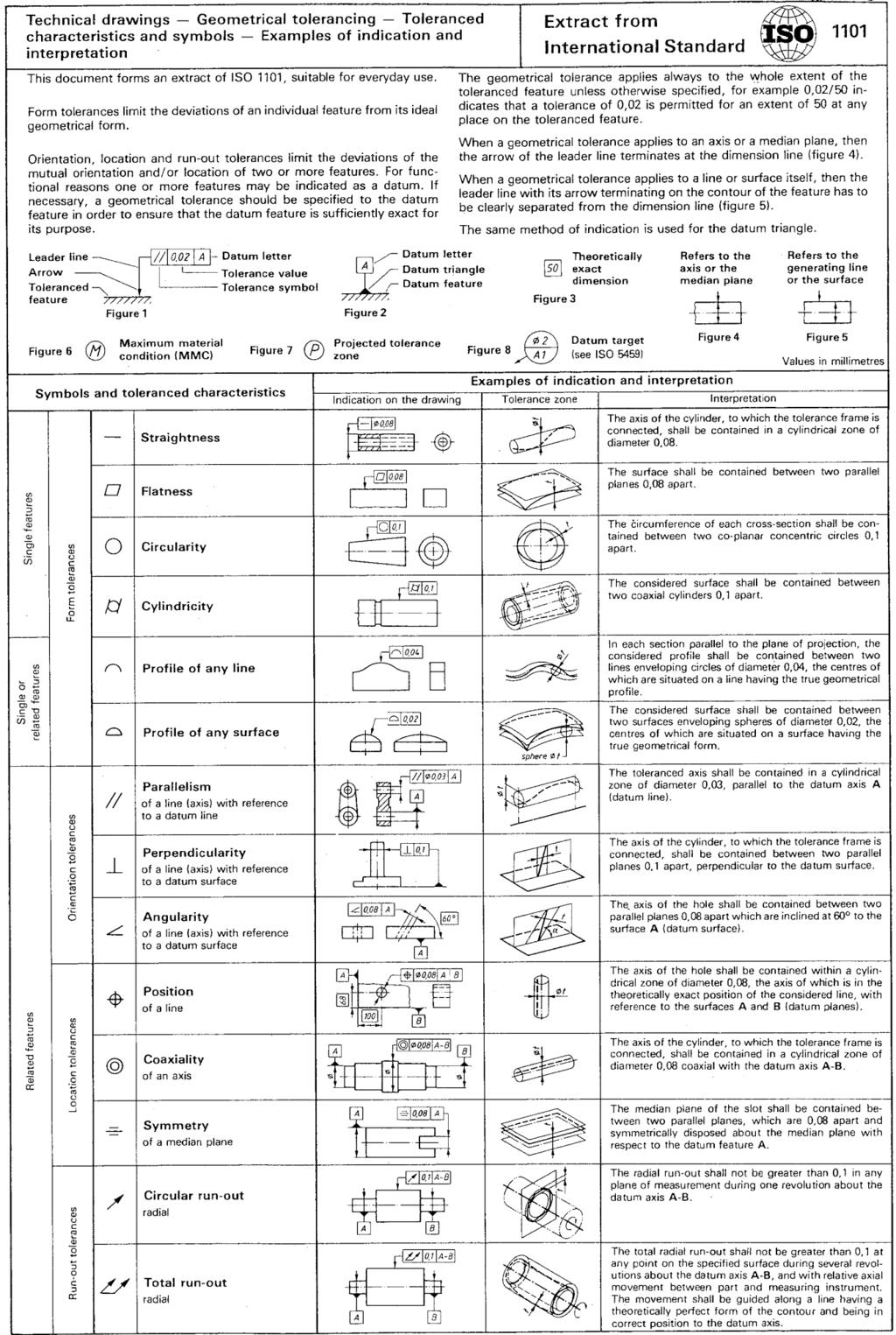
5 5 Maximum Material Principle: This principle requires the specified geometrical tolerance to be applied rigorously only when the feature is in its maximum material condition (MMC). When the feature is finished away from its maximum material limit of size the geometrical tolerance is permitted to increase by the difference between the maximum material limit and the actual finished size of the feature. Obviously the difference cannot exceed the size tolerance specified for the feature and the surface of the feature cannot cross the surface of the virtual condition (envelope). Symbols used on Drawings A number of geometric tolerances have been applied to the Gearbox body shown opposite in Fig 8. Figure 8: Gearbox Body Symbols in SolidWorks Geometric tolerances and Datums can be inserted into drawings in SolidWorks using the tools shown opposite (Annotations toolbar). The required geometric tolerance symbols can be selected and entered in the appropriate edit boxes found in the Properties dialogue box, as shown opposite. ISO 1101 Extract from International Standards On the following page is a single page extract from ISO 1101 (Geometrical Tolerancing), suitable for everyday use. 5
6 6
Geometric Tolerances & Dimensioning
 Geometric Tolerances & Dimensioning MANUFACTURING PROCESSES - 2, IE-352 Ahmed M. El-Sherbeeny, PhD KING SAUD UNIVERSITY Spring - 2015 1 Content Overview Form tolerances Orientation tolerances Location
Geometric Tolerancing
 Geometric Tolerancing Distorted Objects by Suzy Lelievre Scale Transform SALOME Geometry User s Guide: Scale Transform Baek-Ki-Kim-Twisted Stool Mesh Geometric Tolerancing What is it? Geometric Tolerancing
Test Answers and Exam Booklet. Geometric Tolerancing
 Test Answers and Exam Booklet Geometric Tolerancing iii Contents ANSWERS TO THE GEOMETRIC TOLERANCING TEST............. 1 Part 1. Questions Part 2. Calculations SAMPLE ANSWERS TO THE GEOMETRIC TOLERANCING
GEOMETRIC DIMENSIONING AND TOLERANCING (GD&T)
") GEOMETRIC DIMENSIONING AND TOLERANCING (GD&T) Based on ASME Y14.5M-1994 Standard Duration : 4 days Time : 9:00am 5:00pm Methodology : Instructor led Presentation, exercises and discussion Target : Individuals
GEOMETRIC DIMENSIONING AND TOLERANCING (GD&T) Based on ASME Y14.5M-1994 Standard Duration : 4 days Time : 9:00am 5:00pm Methodology : Instructor led Presentation, exercises and discussion Target : Individuals
ME 114 Engineering Drawing II
 ME 114 Engineering Drawing II FITS, TOLERANCES and SURFACE QUALITY MARKS Mechanical Engineering University of Gaziantep Dr. A. Tolga Bozdana Assistant Professor Tolerancing Tolerances are used to control
GEOMETRIC DIMENSIONING AND TOLERANCING (GD&T) Based on ASME Y14.5M-1994 Standard
 Based on ASME Y14.5M-1994 Standard") GEOMETRIC DIMENSIONING AND TOLERANCING (GD&T) Based on ASME Y14.5M-1994 Standard Duration: 4 Days Training Course Content: Day 1: Tolerancing in Engineering Drawing (9:00am-10:00am) 1.0 Geometric Dimensioning
GEOMETRIC DIMENSIONING AND TOLERANCING (GD&T) Based on ASME Y14.5M-1994 Standard Duration: 4 Days Training Course Content: Day 1: Tolerancing in Engineering Drawing (9:00am-10:00am) 1.0 Geometric Dimensioning
ME 410 Mechanical Engineering Systems Laboratory
 ME 410 Mechanical Engineering Systems Laboratory Laboratory Lecture 1 GEOMETRIC TOLERANCING & SOURCES OF ERRORS Geometric dimensioning and tolerancing (GD&T) is a symbolic language used on engineering
Geometric Dimensioning and Tolerancing
 Geometric dimensioning and tolerancing (GDT) is Geometric Dimensioning and Tolerancing o a method of defining parts based on how they function, using standard ASME/ANSI symbols; o a system of specifying
Geometric Dimensioning and Tolerancing
 Geometric Dimensioning and Tolerancing (Known as GDT) What is GDT Helps ensure interchangeability of parts. Use is dictated by function and relationship of the part feature. It does not take the place
A Strategy for Tolerancing a Part 1
 856 SLT LKE OURT SN JOSE, 95133 (408) 251 5329 Strategy for Tolerancing a Part 1 The first step in tolerancing a feature of size, such as the hole in Figure 14-1, is to specify the size and size tolerance
Terms The definitions of 16 critical terms defined by the 2009 standard 1
 856 SALT LAKE COURT SAN JOSE, CA 95133 (408) 251 5329 Terms The definitions of 16 critical terms defined by the 2009 standard 1 The names and definitions of many GD&T terms have very specific meanings.
To help understand the 3D annotations, the book includes a complete tutorial on SOLIDWORKS MBD
 To help understand the 3D annotations, the book includes a complete tutorial on SOLIDWORKS MBD Technical product documentation using ISO GPS - ASME GD&T standards FOREWORD Designers create perfect and
Alessandro Anzalone, Ph.D. Hillsborough Community College, Brandon Campus
 Alessandro Anzalone, Ph.D. Hillsborough Community College, Brandon Campus Sections: 1. Definitions 2. Material Conditions 3. Modifiers 4. Radius and Controlled Radius 5. Introduction to Geometric Tolerances
ENVELOPE REQUIREMENT VERSUS PRINCIPLE OF INDEPENDENCY
 ENVELOPE REQUIREMENT VERSUS PRINCIPLE OF INDEPENDENCY Carmen SIMION, Ioan BONDREA University "Lucian Blaga" of Sibiu, Faculty of Engineering Hermann Oberth, e-mail:carmen.simion@ulbsibiu.ro, ioan.bondrea@ulbsibiu.ro
FOREWORD. Technical product documentation using ISO GPS - ASME GD&T standards
 Technical product documentation using ISO GPS - ASME GD&T standards FOREWORD Designers create perfect and ideal geometries through drawings or by means of Computer Aided Design systems, but unfortunately
AC : CLARIFICATIONS OF RULE 2 IN TEACHING GEOMETRIC DIMENSIONING AND TOLERANCING
 AC 2007-337: CLARIFICATIONS OF RULE 2 IN TEACHING GEOMETRIC DIMENSIONING AND TOLERANCING Cheng Lin, Old Dominion University Alok Verma, Old Dominion University American Society for Engineering Education,
Product and Manufacturing Information (PMI)
") Product and Manufacturing Information (PMI) 1 Yadav Virendrasingh Sureshnarayan, 2 R.K.Agrawal 1 Student of ME in Product Design and Development,YTCEM -Bhivpuri road-karjat, Maharastra 2 HOD Mechanical
Product and Manufacturing Information (PMI) 1 Yadav Virendrasingh Sureshnarayan, 2 R.K.Agrawal 1 Student of ME in Product Design and Development,YTCEM -Bhivpuri road-karjat, Maharastra 2 HOD Mechanical
Introduction. Objectives
 Introduction As more and more manufacturers become immersed in the global economy, standardization plays a critical role in their success. Geometric dimensioning and tolerancing (GD&T) provides a set of
DRAFTING MANUAL. Dimensioning and Tolerancing Rules
 Page 1 1.0 General This section is in accordance with ASME Y14.5-2009 Dimensioning and Tolerancing. Note that Rule #1 is the only rule that is numbered in the 2009 standard. All of the other rules fall
Product and Manufacturing Information(PMI)
") Product and Manufacturing Information(PMI) Ravi Krishnan V 1 Post Graduate Student Department of Mechanical Engineering Veermata Jijabai Technological Institute Mumbai, India ravi.krishnan30@gmail.com
Product and Manufacturing Information(PMI) Ravi Krishnan V 1 Post Graduate Student Department of Mechanical Engineering Veermata Jijabai Technological Institute Mumbai, India ravi.krishnan30@gmail.com
ISO 1101 Geometrical product specifications (GPS) Geometrical tolerancing Tolerances of form, orientation, location and run-out
 Geometrical tolerancing Tolerances of form, orientation, location and run-out") INTERNATIONAL STANDARD ISO 1101 Third edition 2012-04-15 Geometrical product specifications (GPS) Geometrical tolerancing Tolerances of form, orientation, location and run-out Spécification géométrique
INTERNATIONAL STANDARD ISO 1101 Third edition 2012-04-15 Geometrical product specifications (GPS) Geometrical tolerancing Tolerances of form, orientation, location and run-out Spécification géométrique
Geometric Boundaries
 Geometric Boundaries Interpretation and Application of Geometric Dimensioning and Tolerancing (Using the Customary Inch System) Based on ASME Y14.5M-1994 Written and Illustrated by Kelly L. Bramble Published
ASME Y14.5M-1994 GD&T Certification Preparation Examination
 ASME Y14.5M-1994 GD&T Certification Preparation Examination Directions: On the response sheet on the last page, fill in the circle of the letter which best completes the following statements. Do not write
GD&T Reckoner Course reference material for. A Web-based learning system from.
 GD&T Reckoner Course reference material for A Web-based learning system from This is not the complete document. Only Sample pages are included. The complete document is available to registered users of
Representation of features Geometric tolerances. Prof Ahmed Kovacevic
 ME 1110 Engineering Practice 1 Engineering Drawing and Design - Lecture 6 Representation of features Geometric tolerances Prof Ahmed Kovacevic School of Engineering and Mathematical Sciences Room C130,
Measurement and Tolerances
 Measurement and Tolerances Alessandro Anzalone, Ph.D. Hillsborough Community College, Brandon Campus Measurement and Tolerances Sections: 1. Meaning of Tolerance 2. Geometric Dimensioning and Tolerancing
Virtual CAD Parts to Enhance Learning of Geometric Dimensioning and Tolerancing. Lawrence E. Carlson University of Colorado at Boulder
 Virtual CAD Parts to Enhance Learning of Geometric Dimensioning and Tolerancing Lawrence E. Carlson University of Colorado at Boulder Introduction Geometric dimensioning and tolerancing (GD&T) is an important
COMMON SYMBOLS/ ISO SYMBOL ASME Y14.5M ISO FEATURE CONTROL FRAME DIAMETER/ SPHERICAL DIAMETER/ AT MAXIMUM MATERIAL CONDITION
 1 82 COMMON SYMBOLS/ Shown below are the most common symbols that are used with geometric tolerancing and other related dimensional requirements on engineering drawings. Note the comparison with the ISO
Engineering & Design: Geometric Dimensioning
 Section Contents NADCA No. Format Page Frequently Asked Questions -2 s e c t i o n 1 Introduction -2 2 What is GD&T? -2 3 Why Should GD&T be Used? -2 4 Datum Reference Frame -4 4.1 Primary, Secondary,
Geometric Dimensioning & Tolerancing
 Western Technical College 31420350 Geometric Dimensioning & Tolerancing Course Outcome Summary Course Information Description Career Cluster Instructional Level Total Credits 1.00 Total Hours 36.00 Recognition
INDICATION OF FUNCTIONAL DIMENSION ACCORDING ISO GPS HOW SHALL WE APPLICATE?
 INDICATION OF FUNCTIONAL DIMENSION ACCORDING ISO GPS HOW SHALL WE APPLICATE? Karel PETR 1 1 Department of Designing and Machine Components, Faculty of Mechanical Engineering, Czech Technical University
Introduction to GD&T Session 2: Rules and Concepts of GD&T
 Introduction to GD&T Session 2: Rules and Concepts of GD&T An exploration of the language known as Geometric Dimensioning and Tolerancing Instructor: John-Paul Belanger Review Benefits of GD&T The GD&T
INDEX. Datum feature symbol, 21
 INDEX Actual Mating Envelope, 11 Actual Minimum Material Envelope, 11 All Around, 149 ALL OVER, 157, 158,363 Allowed vs. actual deviations from true position, 82 Angularity, 136 axis, 140 line elements,
Concentricity and Symmetry Controls
 Concentricity and Symmetry Controls Alessandro Anzalone, Ph.D. Hillsborough Community College, Brandon Campus Concentricity and Symmetry Controls Sections: 1. Concentricity Control 2. Symmetry Control
A Concise Introduction to Engineering Graphics
 A Concise Introduction to Engineering Graphics Fourth Edition Including Worksheet Series A Timothy J. Sexton, Professor Department of Industrial Technology Ohio University BONUS Book on CD: TECHNICAL GRAPHICS
Answers to Questions and Problems
 Fundamentals of Geometric Dimensioning and Tolerancing Using Critical Thinking Skills 3 rd Edition By Alex Krulikowski Answers to Questions and Problems Second Printing Product #: 1103 Price: $25.00 Copyright
Geometric Boundaries II
 Geometric Boundaries II Interpretation and Application of Geometric Dimensioning and Tolerancing (Using the Inch and Metric Units) Based on ASME Y14.5-2009 (R2004) Written and Illustrated by Kelly L. Bramble
Geometrical product specifications (GPS) Geometrical tolerancing Tolerances of form, orientation, location and run-out
 Geometrical tolerancing Tolerances of form, orientation, location and run-out") Provläsningsexemplar / Preview INTERNATIONAL STANDARD ISO 1101 Fourth edition 2017-02 Geometrical product specifications (GPS) Geometrical tolerancing Tolerances of form, orientation, location and run-out
Provläsningsexemplar / Preview INTERNATIONAL STANDARD ISO 1101 Fourth edition 2017-02 Geometrical product specifications (GPS) Geometrical tolerancing Tolerances of form, orientation, location and run-out
Geometry Controls and Report
 Geometry Controls and Report 2014 InnovMetric Software Inc. All rights reserved. Reproduction in part or in whole in any way without permission from InnovMetric Software is strictly prohibited except for
Geometrical product specifications (GPS) Geometrical tolerancing Tolerances of form, orientation, location and run-out
 Geometrical tolerancing Tolerances of form, orientation, location and run-out") INTERNATIONAL STANDARD ISO 1101 Fourth edition 2017-02 Geometrical product specifications (GPS) Geometrical tolerancing Tolerances of form, orientation, location and run-out Spécification géométrique des
INTERNATIONAL STANDARD ISO 1101 Fourth edition 2017-02 Geometrical product specifications (GPS) Geometrical tolerancing Tolerances of form, orientation, location and run-out Spécification géométrique des
The Author. 1 st Edition 2008 Self-published by Frenco GmbH
 The Author Graduate Engineer (Dipl. Ing., FH) Rudolf Och was born in Bamberg, Germany in 1951. After graduating in mechanical engineering he founded FRENCO GmbH in Nuremberg, Germany in 1978. In the beginning,
Dimensioning. Dimensions: Are required on detail drawings. Provide the shape, size and location description: ASME Dimensioning Standards
 Dimensioning Dimensions: Are required on detail drawings. Provide the shape, size and location description: - Size dimensions - Location dimensions - Notes Local notes (specific notes) General notes ASME
Technical drawings and their interpreta1on. ME Fall 2011 Eradat SJSU Based on notes on Jim Burge and other online resources
 Technical drawings and their interpreta1on ME 297-1 Fall 2011 Eradat SJSU Based on notes on Jim Burge and other online resources Technical drawings Technical drawings Orthographic projec1on Isometric layout
MODELS FOR GEOMETRIC PRODUCT SPECIFICATION
 U.P.B. Sci. Bull., Series D, Vol. 70, No.2, 2008 ISSN 1454-2358 MODELS FOR GEOMETRIC PRODUCT SPECIFICATION Ionel SIMION 1 Lucrarea prezintă câteva modele pentru verificarea asistată a geometriei pieselor,
Datum reference frame Position and shape tolerances Tolerance analysis
 Datum reference frame Position and shape tolerances Tolerance analysis Šimon Kovář Datum reference frame Datum reference frames are typically for 3D. A typical datum reference frame is made up of three
Tolerancing. Summary
 Tolerancing Summary Summary What will we learn We will learn about tolerancing and how important this technique is to mass production. Key points If a feature s size is toleranced, it is allowed to vary
Contents. Notes on the use of this publication
 Contents Preface xxiii Scope Notes on the use of this publication xxv xxvi 1 Layout of drawings 1 1.1 General 1 1.2 Drawing sheets 1 1.3 Title block 2 1.4 Borders and frames 2 1.5 Drawing formats 2 1.6
Engineering drawing. Semester I/II Mechanical Engineering Department Technical University of Gdańsk. Lecture 8
 Engineering drawing Semester I/II Mechanical Engineering Department Technical University of Gdańsk Lecture 8 Representing Tolerance Values Tolerance is the total amount a dimension may vary and is the
Advanced Dimensional Management LLC
 Index: Mechanical Tolerance Stackup and Analysis Bryan R. Fischer Accuracy and precision 8-9 Advanced Dimensional Management 14, 21, 78, 118, 208, 251, 286, 329-366 Ambiguity 4, 8-14 ASME B89 48 ASME Y14.5M-1994
This document is a preview generated by EVS
 INTERNATIONAL STANDARD ISO 1101 Fourth edition 2017-02 Geometrical product specifications (GPS) Geometrical tolerancing Tolerances of form, orientation, location and run-out Spécification géométrique des
Chapter 2: Dimensioning Basic Topics Advanced Topics Exercises
 Chapter 2: Dimensioning Basic Topics Advanced Topics Exercises Dimensioning: Basic Topics Summary 2-1) Detailed Drawings 2-2) Learning to Dimension 2-3) Dimension Appearance and Techniques. 2-4) Dimensioning
SYSTEM OF LIMITS, FITS, TOLERANCES AND GAUGING
 UNIT 2 SYSTEM OF LIMITS, FITS, TOLERANCES AND GAUGING Introduction Definition of limits Need for limit system Tolerance Tolerance dimensions ( system of writing tolerance) Relationship between Tolerance
Specification D data models
 Previous Edition Specification 2017-04 Class: Dimensions, tolerances Class No.:01 Documentation of components by means of 3D data models 516 Part name (for databases) 2009-09 3D data models 852 005 160
David A. Madsen. Faculty Emeritus
 i Q eometric ' ' Dimensioning andtolerancing Ninth Edition Based on ASME Y14.5-2009 AWk A ejacy ofjejtccftence APPROVED PUBLICATION by David A. Madsen President, Madsen Designs Inc. www.madsendesigns.com
AC : TEACHING APPLIED MEASURING METHODS USING GD&T
 AC 2008-903: TEACHING APPLIED MEASURING METHODS USING GD&T Ramesh Narang, Indiana University-Purdue University-Fort Wayne RAMESH V. NARANG is an Associate Professor of Industrial Engineering Technology
Technical Drawing. Preparation of manufacturing documents. Subject module. Independency principle, envelope requirement and two-point size
 Technical Drawing Preparation of manufacturing documents Subject module Independency principle, envelope requirement and two-point size EDITION SWISSMEM Impressum Published by: Title: Edition Swissmem
Gaging Exploration (Applications)
") Gaging Exploration (Applications) PMPA Technical Conference Tomorrow is Today - Conquering the Skills Challenge Chicago, IL April 24, 2018 Gary K. Griffith Corona, California Gary K. Griffith 50+ Years
Gaging Exploration (Applications) PMPA Technical Conference Tomorrow is Today - Conquering the Skills Challenge Chicago, IL April 24, 2018 Gary K. Griffith Corona, California Gary K. Griffith 50+ Years
ISO INTERNATIONAL STANDARD
 INTERNATIONAL STANDARD ISO 286-1 Second edition 2010-04-15 Geometrical product specifications (GPS) ISO code system for tolerances on linear sizes Part 1: Basis of tolerances, deviations and fits Spécification
SPECIFICATION
 Rev. R SPECIFICATION 9-3800 Page 1 of 26 Amphenol Corporation Sidney, New York U TITLE STANDARD SPECIAL USE DESCRIPTION ENGINEERING DRAWING Revisions REV. LETTER ISSUE NUMBER ORIGINATOR DATE APPROVAL M
GD&T - Profile Tolerancing
 GD&T - Profile Tolerancing PMPA Technical Conference Rapid Response to Make the Cut Grand Rapids, MI April 11, 2016 Gary K. Griffith Corona, California Gary K. Griffith 48 Years Exp. Technical Book Author
Geometric elements for tolerance definition in feature-based product models
 Loughborough University Institutional Repository Geometric elements for tolerance definition in feature-based product models This item was submitted to Loughborough University's Institutional Repository
Session 10 Dimensions, Fits and Tolerances for Assembly
 Session 10 Dimensions, Fits and Tolerances for Assembly Lecture delivered by Prof. M. N. Sudhindra Kumar Professor MSRSAS-Bangalore 1 Variations in Production It is necessary that the dimensions, shape
Spatial Demonstration Tools for Teaching Geometric Dimensioning and Tolerancing (GD&T) to First-Year Undergraduate Engineering Students
 to First-Year Undergraduate Engineering Students") Paper ID #17885 Spatial Demonstration Tools for Teaching Geometric Dimensioning and Tolerancing (GD&T) to First-Year Undergraduate Engineering Students Miss Myela A. Paige, Georgia Institute of Technology
Paper ID #17885 Spatial Demonstration Tools for Teaching Geometric Dimensioning and Tolerancing (GD&T) to First-Year Undergraduate Engineering Students Miss Myela A. Paige, Georgia Institute of Technology
A R C H I V E
 A R C H I V E 2 0 0 6 Tutorial Geometric Dimensioning And Tolerancing: A Primer For The BiTS Professional Thomas Allsup Manager of Technology Anida Technologies COPYRIGHT NOTICE The papers in this publication
ISO 1101 Geometrical product specifications (GPS) Geometrical tolerancing Tolerances of form, orientation, location and run-out
 Geometrical tolerancing Tolerances of form, orientation, location and run-out") INTERNATIONAL STANDARD ISO 1101 Third edition 2012-04-15 Geometrical product specifications (GPS) Geometrical tolerancing Tolerances of form, orientation, location and run-out Spécification géométrique
INTERNATIONAL STANDARD ISO 1101 Third edition 2012-04-15 Geometrical product specifications (GPS) Geometrical tolerancing Tolerances of form, orientation, location and run-out Spécification géométrique
ISO INTERNATIONAL STANDARD
 INTERNATIONAL STANDARD ISO 0-3 First edition 00-0-01 Geometrical product specifications (GPS) Dimensional and geometrical tolerances for moulded parts Part 3: General dimensional and geometrical tolerances
Geometrical product specifications (GPS) Geometrical tolerancing Profile tolerancing
 Geometrical tolerancing Profile tolerancing") INTERNATIONAL STANDARD ISO 1660 Third edition 2017-02 Geometrical product specifications (GPS) Geometrical tolerancing Profile tolerancing Spécification géométrique des produits (GPS) Tolérancement géométrique
INTERNATIONAL STANDARD ISO 1660 Third edition 2017-02 Geometrical product specifications (GPS) Geometrical tolerancing Profile tolerancing Spécification géométrique des produits (GPS) Tolérancement géométrique
Tolerancing Fixed Fasteners 1
 + 856 SALT LAKE COURT SAN JOSE, CA 951 (408) 251 529 Tolerancing Fixed Fasteners 1.274- Figure 8-5 Fixed fastener The fixed fastener in Fig. 8-5 is fixed by one or more of the members being fastened. The
Functional Tolerancing and Annotations
 Functional Tolerancing and Annotations Preface Getting Started Basic Tasks Advanced Tasks Workbench Description Customizing Glossary Index Dassault Systèmes 1994-2000. All rights reserved. Preface CATIA
6/23/2016 Copyright 2016 Society of Manufacturing Engineers
 6/23/2016 Copyright 2016 Society of Manufacturing Engineers --- 1 --- GEOMETRIC DIMENSIONING & TOLERANCING FUNDAMENTALS Form Controls & Datums - GDT2 TRT: 25:44 Minutes SCENE 1. GDT01A, CGS: FBI warning
A study of accuracy of finished test piece on multi-tasking machine tool
 A study of accuracy of finished test piece on multi-tasking machine tool M. Saito 1, Y. Ihara 1, K. Shimojima 2 1 Osaka Institute of Technology, Japan 2 Okinawa National College of Technology, Japan yukitoshi.ihara@oit.ac.jp
Fits and Tolerances. Prof Ahmed Kovacevic
 ME 1110 Engineering Practice 1 Engineering Drawing and Design - Lecture 7 Fits and Tolerances Prof Ahmed Kovacevic School of Engineering and Mathematical Sciences Room C130, Phone: 8780, E-Mail: a.kovacevic@city.ac.uk
Manufacturing Processes (2), IE-352 Ahmed M El-Sherbeeny, PhD Spring Manual Process Planning
, IE-352 Ahmed M El-Sherbeeny, PhD Spring Manual Process Planning") Manufacturing Processes (2), IE-352 Ahmed M El-Sherbeeny, PhD Spring 2017 Manual Process Planning Chapter Outline 2 1. Introduction 2. Manual Process Planning 3. Process Plan 4. Part Features Identification
Manufacturing Processes (2), IE-352 Ahmed M El-Sherbeeny, PhD Spring 2017 Manual Process Planning Chapter Outline 2 1. Introduction 2. Manual Process Planning 3. Process Plan 4. Part Features Identification
Empowering GD&T. Introduction. 1. Concepts
 Empowering GD&T Copyright by Multi Metrics, Inc. 2017 All Rights Reserved Introduction The materials contained in this document represent an effort to clarify some of the most important concepts, tools
CATIA Instructor-led Live Online Training Program
 Course Outline Introduction & Understanding to CATIA Environment Introduction & Understanding to CATIA interface Starting new file Understand the Sketcher workbench of CATIA V5 Start a new file in the
Complements and Enhancements of Position Tolerance for Axis and Derived Line Imposed by ISO Standards
 Complements and Enhancements of Position Tolerance for Axis and Derived Line Imposed by ISO Standards Yiqing Yan1 and Martin Bohn2 Dimensional Management, Research & Development, Mercedes-Benz Cars, Daimler
PolyWorks Inspector Standard. 3 Day Course
 PolyWorks Inspector Standard INTRODUCTION TO POLYWORKS Workspace Manager Basic Options File and Project Structures PolyWorks License Manager INTRODUCTION TO POLYWORKS INSPECTOR User Interface Basic Options
CAD-CAM-CAE Examples
 CAD-CAM-CAE Examples example title: example number: example level: CAx system: Related material part with TÁMOP Job Description: Shaft type component (CAD) ÓE-A06a basic - medium - advanced CATIA v5 CAD
MEMORANDUM REPORT ARCCB-MR GEOMETRIC DIMENSIONING AND TOLERANCING TO 1982 THE DIFFERENCES IN THE STANDARDS DAVID H.
 AD MEMORANDUM REPORT ARCCB-MR-94040 GEOMETRIC DIMENSIONING AND TOLERANCING - 1946 TO 1982 THE DIFFERENCES IN THE STANDARDS DAVID H. HONSINGER OCTOBER 1994 US ARMY ARMAMENT RESEARCH, DEVELOPMENT AND ENGINEERING
: Fits and Tolerances
 Fits and Tolerances CONTENTS Why tolerances and fits are required? Due to the inevitable inaccuracy of manufacturing methods, a part cannot be made precisely to a given dimension, the difference between
Trade of Toolmaking. Module 5: Press Tools, Jigs & Fixtures, Mouldmaking Unit 2: Blanking Tool (Unguided) Phase 2. Published by
 Phase 2. Published by") Trade of Toolmaking Module 5: Press Tools, Jigs & Fixtures, Mouldmaking Unit 2: Blanking Tool (Unguided) Phase 2 Published by SOLAS 2014 Unit 2 1 Table of Contents Document Release History... 3 Unit Objective...
Trade of Toolmaking Module 5: Press Tools, Jigs & Fixtures, Mouldmaking Unit 2: Blanking Tool (Unguided) Phase 2 Published by SOLAS 2014 Unit 2 1 Table of Contents Document Release History... 3 Unit Objective...
ENGINEERING GRAPHICS ESSENTIALS. (A Text and Lecture Aid) Second Edition. Kirstie Plantenberg University of Detroit Mercy SDC PUBLICATIONS
 Second Edition. Kirstie Plantenberg University of Detroit Mercy SDC PUBLICATIONS") ENGINEERING GRAPHICS ESSENTIALS (A Text and Lecture Aid) Second Edition Kirstie Plantenberg University of Detroit Mercy SDC PUBLICATIONS Schroff Development Corporation www.schroff.com www.schroff-europe.com
ENGINEERING GRAPHICS ESSENTIALS (A Text and Lecture Aid) Second Edition Kirstie Plantenberg University of Detroit Mercy SDC PUBLICATIONS Schroff Development Corporation www.schroff.com www.schroff-europe.com
Copyright Warning & Restrictions
 Copyright Warning & Restrictions The copyright law of the United States (Title 17, United States Code) governs the making of photocopies or other reproductions of copyrighted material. Under certain conditions
Inspection and Measurement
 Inspection and Measurement Inspection An action to insure what is being manufactured conforms to the specifications by attributes use of gages: go or no-go by variables use of calibrated instruments Measurement
Spin-On Filter Threads
 Technical Service Bulletin 94-3R2 Spin-On Filter Threads The spin-on filter has become the most popular and widely applied design for liquid filtration products. Among other physical and performance differences,
Recommended Dimensional Guidelines for Single Screws
 The Society of the Plastics Industry s Machinery Component Manufacturers Division Recommended Dimensional Guidelines for Single Screws The following recommendations for single screws of injection molding
ISO 2692 INTERNATIONAL STANDARD
 INTERNATIONAL STANDARD ISO 2692 Second edition 2006-12-15 Geometrical product specifications (GPS) Geometrical tolerancing Maximum material requirement (MMR), least material requirement (LMR) and reciprocity
NEW STANDARDS IN THE FIELD OF GEOMETRICAL PRODUCT SPECIFICATIONS
 NEW STANDARDS IN THE FIELD OF GEOMETRICAL PRODUCT SPECIFICATIONS Pavlina TOTEVA, Dimka VASILEVA and Nadezhda MIHAYLOVA ABSTRACT: The essential tool for improving product quality and reducing manufacturing
Drafting techniques. Preparation of manufacturing drawings. Speciality module. Preparing engineering drawings according to standards EDITION SWISSMEM
 Drafting techniques Preparation of manufacturing drawings Speciality module Preparing engineering drawings according to standards EDITION SWISSMEM Impressum Published by: Title: Edition Swissmem Drafting
1.0 What is tolerance analysis? 2.0 What is Tolerance Stackup? 3.0 Generally, the Tolerance Stackup Process 4.0 Method and Types of Tolerance
 TOLERANCE ANALYSIS 1.0 What is tolerance analysis? 2.0 What is Tolerance Stackup? 3.0 Generally, the Tolerance Stackup Process 4.0 Method and Types of Tolerance Analysis 5.0 Worst-case Tolerance Stackup
Continuous thick. Continuous thin. Continuous thin straight with zigzags. Dashed thin line. Chain thin. Chain thin double dash
 Types of line used Continuous thick Used for visible outlines and edges. Continuous thin Used for projection, dimensioning, leader lines, hatching and short centre lines. Continuous thin straight with
and mean roughness index R a of the micro-irregularities. Following are the definitions of the terms indicated in Fig. 16.1:
 It is not possible to achieve in practice, a geometrically ideal surface of a component and hence, production drawings of components must also contain information about the permissible surface conditions.
Australian Standard. ISO system of limits and fits. Part 1: Bases of tolerances, deviations and fits AS ISO 286-1:1988
 AS 1654.1 1995 ISO 286-1:1988 Australian Standard ISO system of limits and fits Part 1: Bases of tolerances, deviations and fits This Australian Standard was prepared by Committee ME/27, Engineering Tolerance
Technical product documentation and specification
 BS 8888:2013 BSI Standards Publication Technical product documentation and specification BS 8888:2013 BRITISH STANDARD Publishing and copyright information The BSI copyright notice displayed in this document
AC : CALCULATION OF TOLERANCE STACKS USING DIRECT-POSITION APPROACH IN GEOMETRIC DIMENSIONING AND TOLERANCING
 AC 2009-138: CALCULATION OF TOLERANCE STACKS USING DIRECT-POSITION APPROACH IN GEOMETRIC DIMENSIONING AND TOLERANCING Cheng Lin, Old Dominion University American Society for Engineering Education, 2009
Applications of Geometric Tolerancing to Machine Design
 Applications of Geometric Tolerancing to Machine Design First Edition 1 Faryar Etesami Design for Fit Applications of Geometric Tolerancing to Machine Design First Edition Faryar Etesami Mechanical and
Pattern Inspection with Variable Geometric Tolerance Limits
 Pattern Inspection with Variable Geometric Limits From Disregarding to Fully Applying Variable Feature Bonus and Datum Shift s in a Pattern Inspection By Paul F. Jackson Variable Limit Specifications and
Unit4 31. UnitS 39. Unit 6 47
 Preface..................... xi About the Author......... xiii Acknowledgments... xiv Unit 1 1 Bases for Interpreting Drawings........ I Visible Lines............. 3 Lettering on Drawings... 3 Sketching...
A Conceptual Data Model of Datum Systems
 [J. Res. Natl. Inst. Stand. Technol. 104, 349 (1999)] A Conceptual Data Model of Datum Systems Volume 104 Number 4 July August 1999 Michael R. McCaleb National Institute of Standards and Technology, Gaithersburg,
ZEISS ACADEMY METROLOGY. COOKBOOK Measuring strategies for tactile Coordinate Metrology Reading Sample
 ZEISS ACADEMY METROLOGY COOKBOOK Measuring strategies for tactile Coordinate Metrology Reading Sample Overview Content Introduction 11 Understanding Measuring Strategies Cookbook...12 Measuring Strategies