Table of Contents. Fundamentals of Screw Thread Technology Definitions and Terminology Gage Design Contacts...
|
|
|
- Augustine Francis
- 6 years ago
- Views:
Transcription

1 1 Distributed by: Gage Crib Worldwide Inc 6701 Old 28th St SE, Suite B Grand Rapids, MI USA Phone: Web:
2 Table of Contents SECTION 1: Fundamentals of Screw Thread Technology SECTION 2: Definitions and Terminology SECTION 3: Gage Design Contacts SECTION 4: Technical Considerations SECTION 5: Plating, Metric and RFQ

3 Distributed by: Gage Crib Worldwide Inc 6701 Old 28th St SE, Suite B Grand Rapids, MI USA Phone: Web:
4 4 FUNDAMENTALS OF SCREW THREAD TECHNOLOGY Screw Thread Designation EXAMPLE: UNJF - 3A (B).3125 = Nominal Diameter = Maximum Major Diameter 24 = Number of threads per inch UN = Unified National (60 V-thread) J = Controlled root radius High Strength (Minor diameter increased from UN to UNJ.) F = Fine thread series 3 = Thread class A = External thread B = Internal thread Screw Thread Assembly
5 5 SECTION 1 Functional Diameter Size Pitch Diameter Size + Variations of Thread Elements and Characteristics = Functional Diameter Size The Functional diameter size is the Pitch diameter size plus the cumulative effect of variations in lead, (including uniformity of helix) flank angle, taper, and roundness. The Functional size is the measured value of the maximum material size of either a product internal or external screw thread. Thread Form VariationÚ ÙFS PDÚ Pitch Diameter Size The Pitch diameter size is defined as the diameter of a cylinder that passes through the thread profile of either a product internal or external screw thread to make the widths of thread ridge and thread groove eual on both sides of the thread. The Pitch diameter is the measured value of the minimum material limit of size of either a product internal or external screw thread. Width of Thread Ridge = Width of Thread Groove PDÚ THREAD RIDGE = THREAD GROOVE à ß ß à
6 6 FUNDAMENTALS OF SCREW THREAD TECHNOLOGY Reference Federal Standard H28/20 Systems of Gaging t SYSTEM 21.. GO/NO GO GAGING System 21 provides for interchangeable assembly with functional size control at the maximum material limits within the length of standard gaging elements; and also control of character-istics identified as NOT-GO functional diameters or as HI (Internal) and LO (External) functional diameters. These functional gages provide some control at the minimum material limit when there is little variation in thread form characteristics such as lead, flank angle, taper and roundness. t SYSTEM 22.. VARIABLES INDICATING TYPE GAGING System 22 provides for interchangeable assembly with functional size control at the maximum material limits within the length of standard gaging elements; and also control of the minimum material size limits over the length of the full thread. Other thread characteristics such as lead, flank angle, taper and roundness variations are confined within these limits with no specific control of their magnitudes. For UNJ and MJ external threads, control is also provided for the thread root radius and rounded root minor diameter. t SYSTEM 23. SAFETY CRITICAL t 5.2 ACCEPTABILITY. Screw thread acceptability criteria are in accordance with Section 6 of ASME B1.3M Also see subsection 5.7. Other Reference Standards t ASME B1.1 Unified Inch Screw Threads. t ASME B1.2 Gages and Gaging for Unified Inch Screw Threads. t ASME B1.3M Screw Thread Gaging Systems for Dimensional Acceptability Inch and Metric Threads (UN, UNR, UNJ, M and MJ).
7
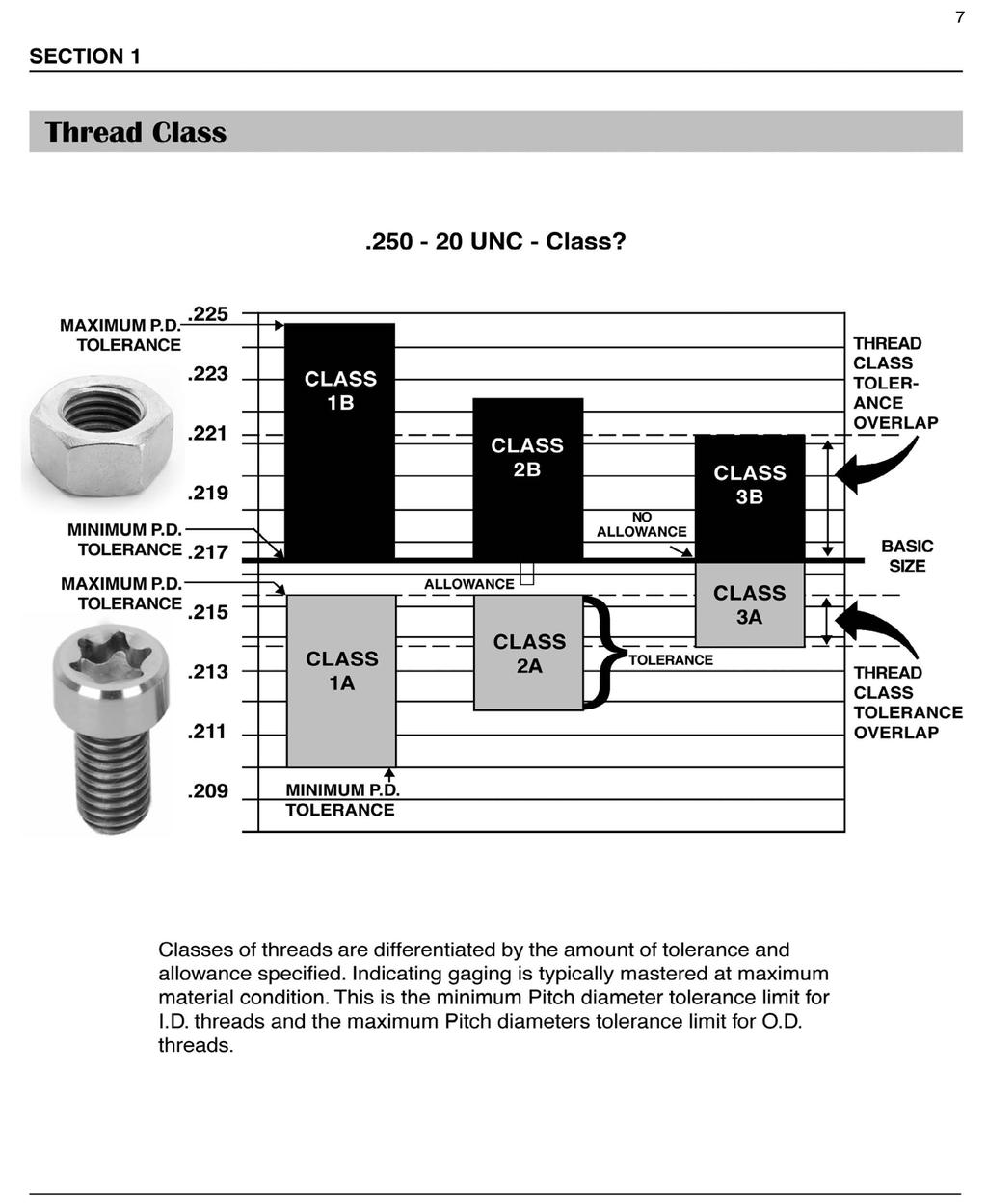
8 7 SECTION 1 Thread Class UNC - Class?.225 MAXIMUM P.D. TOLERANCE.223 MINIMUM P.D. TOLERANCE MAXIMUM P.D. TOLERANCE CLASS 1B CLASS 1A ALLOWANCE CLASS 2B b CLASS 2A NO ALLOWANCE }TOLERANCE CLASS 3B CLASS 3A THREAD CLASS TOLER- ANCE OVERLAP BASIC SIZE THREAD CLASS TOLERANCE OVERLAP.209 MINIMUM P.D. TOLERANCE Classes of threads are differentiated by the amount of tolerance and allowance specified. Indicating gaging is typically mastered at maximum material condition. This is the minimum Pitch diameter tolerance limit for I.D. threads and the maximum Pitch diameters tolerance limit for O.D. threads.
9 8 DEFINITIONS AND TERMINOLOGY FIGURE 1 Screw Thread The Screw Thread is a ridge, usually of uniform section and produced by forming a groove as a helix on the external or internal surface of a cylinder, or as a conical spiral on the external or internal surface of a cone. A screw thread formed on a cylinder is known as a straight or parallel thread, to distinguish it from a tapered thread that is formed on a cone. FIGURE 2 Thread A thread is a portion of a screw thread encompassed by one ridge wrapped around a cylinder or cone for one complete turn. Single Start Thread A single start thread is one having one ridge wrapped around a cylinder or cone for the total length. FIGURE 3 Multiple-Start Thread A multiple-start thread is one that has two or more ridges wrapped around a cylinder or cone for the total length. External Thread An external thread is on a cylindrical or conical external surface (reference Figures 1, 2 and 3).
10 9 SECTION 2 FIGURE 4 Internal Thread An internal thread is on a cylindrical or conical internal surface. FIGURE 5 FIGURE 6 Right-Hand Thread A thread is a righthand thread if, when viewed axially, it winds in a clockwise and receding direction. A thread is considered right-hand unless specifically shown otherwise. Left-Hand Thread A thread is a left-hand thread if, when viewed axially, it winds in a counterclockwise and receding direction. All left-hand threads are designated LH. FIGURE 7 Flank of Thread The flank (or side) of the ridge. The flank surface intersection with an axial plane is theoretically a straight line. Crest of Thread The crest is that surface of the thread that joins the flank of the thread and is farthest from the cylinder or cone from which the thread projects. Root of Thread The root is that surface of the thread that joins the flanks of adjacent thread forms and is identical with or immediately next to the cylinder or cone from which the thread projects.
11 10 DEFINITIONS AND TERMINOLOGY Maximum Material Condition The condition where the product screw thread contains the maximum amount of material. Definitions & Terminology Minimum Material Condition The condition where the product screw thread contains the minimum amount of material. Tolerance The total amount of variation permitted for the size of a dimension. It is the difference between the maximum limit of size and the minimum limit of size for a given thread size. Allowance The difference between the design (maximum material) size and the basic size. Basic Size The basic size is that size from which the limits of size are derived by the application of allowances and tolerances. Design Size The design size is the basic size with allowance applied, from which the limits of size are derived by the application of tolerance. If there is no allowance, the design size is the same as the basic size. Nominal Size The nominal size is the designation that is used for general identifical of the diameter. Thread series Thread series are groups of diameters/pitch combinations distinguished from each other by the number of threads per inch applied to specific diameters. Classes of Thread Classes of threads are distinguished from each other by the amount of tolerance or tolerance and allowance specified.
12 11 SECTION 2 Pitch Pitch is not pitch diameter, threads per inch (TPI), nor is it LEAD, but it is the axial distance defined in (x,y) between any point on a thread to the corresponding point on the adjacent thread. Definitions & Terminology Pitch = Number of thread starts Number of threads per inch Lead Lead is the axial advance per unit rotation for a given pitch distance. Pitch euals lead when the thread form is ideal. Major Cylinder The major cylinder bounds the crest of an external straight thread or the root of an internal straight thread. Minor Cylinder The minor cylinder bounds the root of an external straight thread or the crest of an internal thread. Pitch Cylinder The pitch cylinder is one of such diameter and location of its axis that its surface would pass through a straight thread in such a manner as to make the width of the thread ridge and the thread groove eual. Pitch Line The pitch line is linear and parallel to the center line of the pitch cylinder. Defined where thread ridge and thread groove are eual along the length of the thread. Thread Axis The thread axis is the axis of its pitch cylinder. Actual Size An actual size is a measured size. REFERENCE: ASME B1.7M
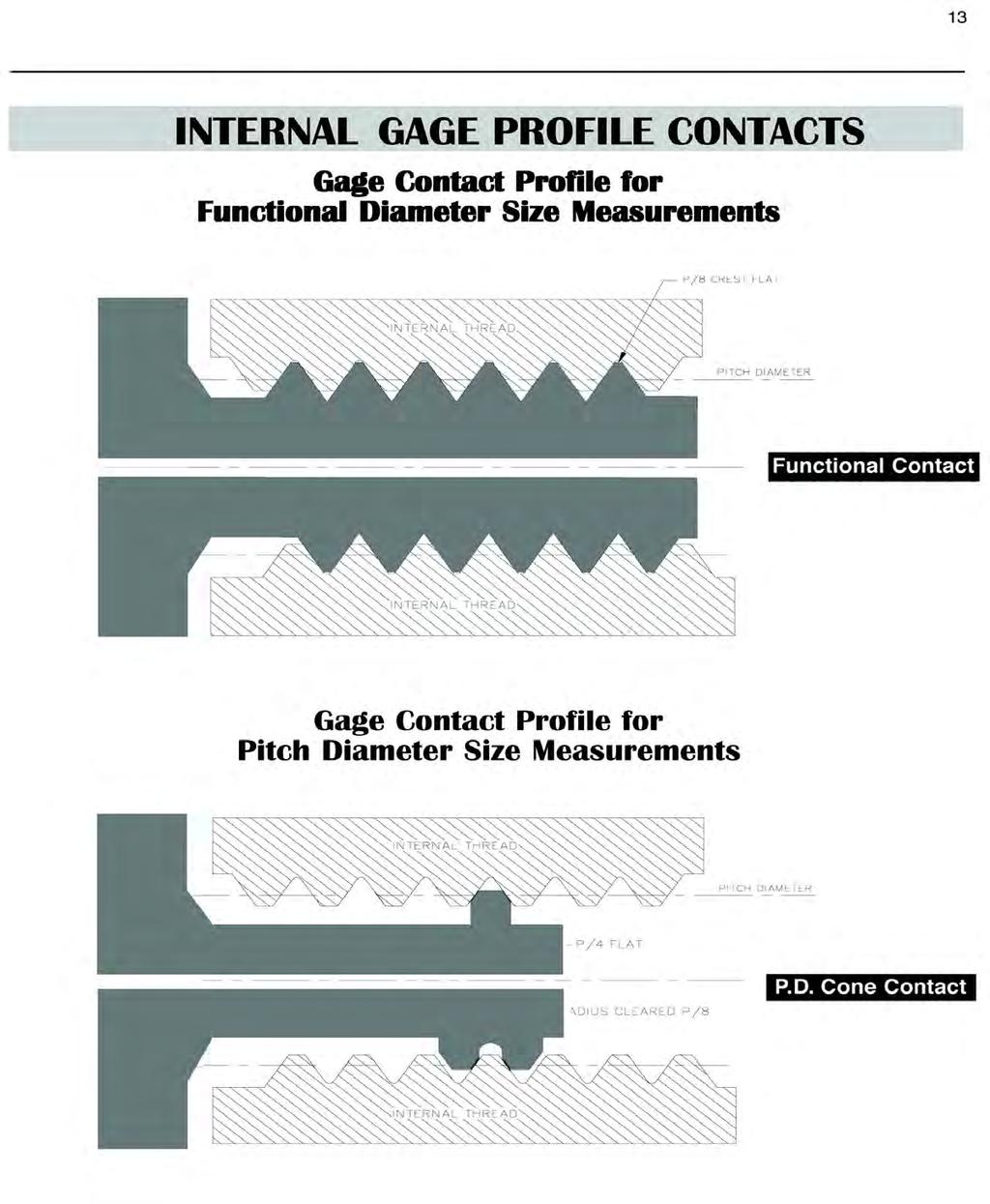
13 12 UN GAGE PROFILE CONTACTS Gage Contact Profile for Functional Diameter Size Measurements GAGE DESIGN CONTACTS Functional Contact PITCH DIAMETER SIZE FUNCTIONAL DIAMETER SIZE Product External Thread Functional Contact Gage Contact Profile for Pitch Diameter Size Measurements P.D. Vee Contact Product External Thread P.D. Cone Contact
14
15 13 INTERNAL UN GAGE PROFILE CONTACTS Gage Contact Profile for Functional Diameter Size Measurements Gage Contact Profile for Pitch Diameter Size Measurements
16
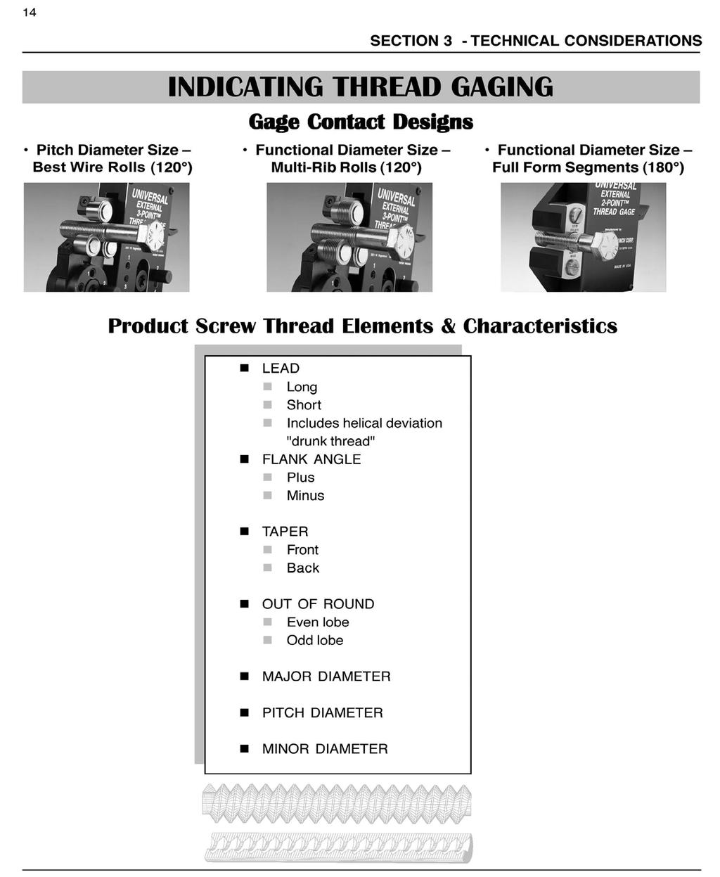
17 14 Pitch Diameter Size Cone & Vee Rolls (120 ) SECTION 3 - TECHNICAL CONSIDERATIONS INDICATING THREAD GAGING Gage Contact Designs Functional Diameter Size Multi-Rib Rolls (120 ) Functional Diameter Size Full Form Segments (180 ) Product Screw Thread Elements & Characteristics n n n n n n n LEAD n Long n Short n Includes helical deviation "drunk thread" FLANK ANGLE n Plus n Minus TAPER n Front n Back OUT OF ROUND n Even lobe n Odd lobe MAJOR DIAMETER PITCH DIAMETER MINOR DIAMETER
18
19 15 SECTION 4 Anatomy of a UN or UNJ Screw Thread UNJ.3125P UN n H = Height of the Fundamental Triangle: (Cos 30 / TPI) or (Cos 30 x P) n FLANK ANGLES are made up of the two half angles of 30 each for the 60 included angle. n MAJOR DIAMETER is at P/8 or 0.125P n PITCH DIAMETER is at P/2 or 0.500P n MINOR DIAMETER is at P/4 or 0.250P for UN or UNJ is at 5P/16 or.3125p n n TPI = Number of Threads per Inch N = Number of Thread Starts n P = Pitch P = N/TPI
20 16 VARIATIONS Lead TECHNICAL CONSIDERATIONS ÙPÚ Ideal Lead Ú Long Lead Ú Short Lead Ú Lead is the axial advance per unit rotation for a given pitch distance.
21 17 SECTION 4 VARIATIONS Flank Angle A virtual variation in effective diameter also occurs if the flank angle deviates from its specified value. FIGURE 12. Virtual Variation of Effective Diameter due to Errors in Flank Angle. Reference: Sidders; Guide to World Screw Threads, page 212, Figure 12.
22 18 DIFFERENTIAL GAGING Taper TECHNICAL CONSIDERATIONS P.D. Vee Contact Ý Û Þ Product External Thread Ý Û P.D. Cone Contact Þ To measure Taper: Use the Pitch diameter gage (cone and vee) and measure at positions along the length of thread without rotating the part. Any deviation of the dial indicator needle will tell the direction and magnitude of the tapered condition.
23 19 SECTION 4 DIFFERENTIAL GAGING Out-of-Round Segment Roll EVEN LOBE 180 ODD LOBE 120 Roll Roll Segment To measure Out-of-Round: Use the 180 Functional segment to capture the full magnitude of an egg-shaped (even lobe) out-of-round. Use the 120 cone and vee or multi-rib roll contacts for a tri-lobe (odd lobe) out-of-round. When using the Functional diameter gage (multi-rib or segment) rotate the part to observe the largest indicated value for O.D. and the smallest value for I.D. threads. When using the Pitch diameter gage (cone and vee) rotate the part to observe the smallest indicated value for O.D. and the largest value for I.D. threads.
24 20 DIFFERENTIAL GAGING Lead TECHNICAL CONSIDERATIONS Functional Contact Product External Thread FULL ENGAGEMENT Functional Contact Functional Contact FIRST FULL THREAD Product External Thread Functional Contact To measure Lead: Use the 180 Functional segment or the 120 Functional multi-rib roll. Compare the indicated values for product full engagement, then the product's first full thread. The first full thread is usually the second pitch in from the end. The difference between the two indicated values is the total effect of diametral lead variation with respect to the pitch diameter tolerance. NOTE: Multi-rib (zero lead) functional rolls do not detect a helical deviation (drunk thread).
25 21 SECTION 4 DIFFERENTIAL GAGING Flank Angle Functional Contact FIRST FULL THREAD Product External Thread Functional Contact P.D. Vee Contact SAME THREAD Product External Thread P.D. Cone Contact To measure Flank Angle: Use the Functional gage contact (full form segment or multirib roll) and a Pitch diameter gage contact (cone and vee). Engage the product's first full thread functional measurement and compare it with the measurement of the same thread on the Pitch diameter gage. The difference between both indicated values represents the diametral effect of flank angle variation with respect to Pitch diameter tolerance.
26 22 TECHNICAL CONSIDERATIONS DIFFERENTIAL GAGING System 22 = Maximum PD Tolerance Limit = Minimum PD Tolerance Limit 1 Functional Diameter Size Pitch Diameter Size PASS The uality of the thread form is ideal. The thread size is positioned at the mean of the Pitch diameter tolerance. This product passes Systems 21, 22 and Functional Diameter Size Pitch Diameter Size PASS The uality of the thread form is poor. However, it is still within acceptable Pitch diameter tolerance limits. This product passes Systems 21 and 22. May not pass System 23.
27 23 SECTION 4 DIFFERENTIAL GAGING System 22 = Maximum PD Tolerance Limit = Minimum PD Tolerance Limit 3 Functional Diameter Size Pitch Diameter Size FAIL The uality of the thread form is poor. Functional diameter size has exceeded the maximum material limit. This product may not assemble. Product fails Systems 21, 22 and Functional Diameter Size Pitch Diameter Size FAIL The uality of the thread form is poor. Pitch diameter size has exceeded minimum material limit. This product fails Systems 22 and 23, but may pass System 21.
28 24 PLATING, METRIC & RFQ Effect on Pitch Diameter with respect to the addition of Plating and Coating Normal to Surface DIAMETRAL INCREASE ON PITCH DIAMETER SIZE Effect on Functional Size with respect to the addition of Plating and Coating on Lead Variation DIAMETRAL INCREASE ON FUNCTIONAL SIZE
29 25 SECTION 5 ISO Metric Threads ISO Basic Designations SIZE is designated by letter M followed by NOMINAL SIZE & PITCH (both in mm) separated by sign X. EXAMPLE: M16X2 METRIC THREAD SIZE To convert MM Pitch to TPI M1.6X0.35 M1.8X0.35 M2X0.4 M2.2X0.45 M6X1 M7X1 M8X1.25 M8X1 M16X2 M16X1.5 M18X2.5 M18X1.5 Coarse Fine Coarse Fine Coarse Fine 25.4/Pitch = TPI EXAMPLES: 2 mm = TPI.35 mm = TPI
30 ISO Metric Threads ISO Product Tolerance Symbols PLATING, METRIC & RFQ

31 Distributed by: Gage Crib Worldwide Inc 6701 Old 28th St SE, Suite B Grand Rapids, MI USA Phone: Web: 30
ROLL AND SEGMENT SELECTION (Back to Contents)
") ROLL AND SEGMENT SELECTION (Back to Contents) Routinely thread comparators are used to analyze and distinguish the following characteristics of a thread: functional diameter, pitch diameter, major diameter,
ROLL AND SEGMENT SELECTION (Back to Contents) Routinely thread comparators are used to analyze and distinguish the following characteristics of a thread: functional diameter, pitch diameter, major diameter,
UNIT 9b: SCREW FASTENERS Introduction Functions Screw Features Elements Terms of a Thread Profile
 UNIT 9b: SCREW FASTENERS Introduction A mechanical screw is a cylinder or cone that has a helical ridge called a thread. A helix has one or more turns, so a screw can have several turns. If the helix is
AN AMERICAN NATIONAL STANDARD. ASME BI (Revision of ASME/ANSI BI )
") œ The Mechanical American Engineers Society of AN AMERICAN NATIONAL STANDARD ASME BI.5-1997 (Revision of ASME/ANSI BI.5-1988) CONTENTS Foreword... iii Standards Committee Roster... v I General... 1 1.1
œ The Mechanical American Engineers Society of AN AMERICAN NATIONAL STANDARD ASME BI.5-1997 (Revision of ASME/ANSI BI.5-1988) CONTENTS Foreword... iii Standards Committee Roster... v I General... 1 1.1
TAPS AND THREADING DIES
 872 TAPS AN THRAING IS TAPS AN THRAING IS General dimensions and tap markings given in the ASM/ANSI Standard B94.9-1987 for straight fluted taps, spiral pointed taps, spiral pointed only taps, spiral fluted
Spin-On Filter Threads
 Technical Service Bulletin 94-3R2 Spin-On Filter Threads The spin-on filter has become the most popular and widely applied design for liquid filtration products. Among other physical and performance differences,
FASTENERS. Aylin YENİLMEZ GÜRKÖK
 FASTENERS Aylin YENİLMEZ GÜRKÖK FASTENERS A fastener is a hardware device that mechanically joins or affixes two or more objects together. Welding, Soldering, Nuts & Bolts, Washers, Screws, Clips, Clamps,
Program Pin Measurement for External Involute Worms Introduction
 Program 60-1443 Pin Measurement for External Involute Worms Introduction This model calculates the measurement over pins for an involute helicoid worm. Measurement over pins is used extensively in the
Provläsningsexemplar / Preview INTERNATIONAL STANDARD. Aerospace MJ threads Part 1: General requirements
 INTERNATIONAL STANDARD ISO 5855-1 Third edition 1999-10-15 Aerospace MJ threads Part 1: General requirements Aéronautique et espace Filetage MJ Partie 1: Exigences générales A Reference number Foreword
Thread and End Connection
 www.swagelok.com and End Connection I d e n t i f i c a t i o n G u i d e Contents Introduction and End Connection Terminology.. 4 General Terminology................... 5 Step-by-Step Identification
Geometric Dimensioning and Tolerancing
 Geometric Dimensioning and Tolerancing (Known as GDT) What is GDT Helps ensure interchangeability of parts. Use is dictated by function and relationship of the part feature. It does not take the place
Screw Threads: Nomenclature, Definitions, and Letter Symbols
 ASME B1.7-2006 (Revision of ANSI/ASME B1.7M-1984) Screw Threads: Nomenclature, Definitions, and Letter Symbols A N A M E R I C A N N A T I O N A L S T A N D A R D ASME B1.7-2006 (Revision of ANSI/ASME
The Engineer s Guide to Identifying Lead Screw Thread Forms
 The Engineer s Guide to Identifying Lead Screw Thread Forms Thread Forms There are hundreds of different thread forms that have been designed over several decades. There are only a few specific thread
COMMON SYMBOLS/ ISO SYMBOL ASME Y14.5M ISO FEATURE CONTROL FRAME DIAMETER/ SPHERICAL DIAMETER/ AT MAXIMUM MATERIAL CONDITION
 1 82 COMMON SYMBOLS/ Shown below are the most common symbols that are used with geometric tolerancing and other related dimensional requirements on engineering drawings. Note the comparison with the ISO
JCutting Tools aerospace
 JCutting Tools aerospace AppLIcations A286 Fasteners The new and improved Jarhook is the best available tap for A286 fasteners. During extensive testing the Jarhook surpassed all of the competition in
Quality Policy Statement
 Table of Contents Quality Policy Statement... Page 2 Warranty Statement.... Page 2 Calibration Service... Page 3 Facility... Page 4, 5 Machining, Grinding, Leadscrew Products And Services.... Page 5 Thread
BOLTS AND NUTS Square Bolts( Table 1 ) Hex Nuts ( Table 7 ) Heavy Hex Nuts (Table 7) Heavy Hex Structural Bolts ( Table 2 )
 Hex Nuts ( Table 7 ) Heavy Hex Nuts (Table 7) Heavy Hex Structural Bolts ( Table 2 )") BOLTS AND NUTS 1493 An externally threaded fastener that must be assembled with a nut to perform its intended service is a bolt. (Example: heavy hex structural bolt.) An externally threaded fastener that
BOLTS AND NUTS 1493 An externally threaded fastener that must be assembled with a nut to perform its intended service is a bolt. (Example: heavy hex structural bolt.) An externally threaded fastener that
THREAD CUTTING & FORMING
 THREAD CUTTING & FORMING Threading, Thread Cutting and Thread Rolling: Machining Threads on External Diameters (shafts) Tapping: Machining Threads on Internal Diameters (holes) Size: Watch to 10 shafts
SCREW THREADS. = minor diameter. d 3. d 2. = pitch diameter
 ISO : 6 Part 2 DIN : Part /20 Metric (ISO) screw thread, coarse series -M- T-00 T-002 for M to incl. M,4, fit H/6h The bold lines indicate the maximum material profiles. The maximum material profile of
( This link will provide you with a list of all ISO-6983 G-Codes
 CUSTOM HAZARDS CUSTOM HAZARDS CUSTOM HAZARDS In this lesson I am going to explain how to circle interpolate a 1/8-27 NPT with a formed thread E-Mill using G-Code on a vertical mill. I have provided the
TH READ GAGES Certification of Compliance to Class (Short Form)... No Charge Certification of Calibration to Size (Long Form)...$15.
... No Charge Certification of Calibration to Size (Long Form)...$15.") New Swanson Gages TH READ GAGES Certification of Compliance to Class (Short Form)... No Charge Certification of Calibration to Size (Long Form)...$. / member TA PER PIPE GAGES Certification of Compliance
New Swanson Gages TH READ GAGES Certification of Compliance to Class (Short Form)... No Charge Certification of Calibration to Size (Long Form)...$. / member TA PER PIPE GAGES Certification of Compliance
1/2/2016. Lecture Slides. Screws, Fasteners, and the Design of Nonpermanent Joints. Reasons for Non-permanent Fasteners
 Lecture Slides Screws, Fasteners, and the Design of Nonpermanent Joints Reasons for Non-permanent Fasteners Field assembly Disassembly Maintenance Adjustment 1 Introduction There are two distinct uses
Specification for Threading, Gauging and Thread Inspection of Casing, Tubing, and Line Pipe Threads
 Standard. It shall not be reproduced or circulated or quoted, in whole or in part, outside of API committee activities except with the approval of the Chairman of the committee having jurisdiction and
The Catalogue of Nomura Tool Works Co., Ltd. Tool manufacturing since 1954 Bent Shank Taps Nib Taps Nut Taps
 The Catalogue of Nomura Tool Works Co., Ltd. Tool manufacturing since 1954 Bent Shank Taps Nib Taps Nut Taps Introduction In today's highly developed machine industry, a tap is a cutting tool that requires
Tap Drill Chart. Metric Tap Drill Size (Recommended Drill Sizes Suitable for 6H Tolerance) Roll Form Tap Drill Size
 Roll Form Tap Drill Size") Tap Drill Chart Tap Size Nom. Size Tap Cutting Tap Drill Size Metric Tap Drill Size (Recommended Drill Sizes Suitable for 6H Tolerance) Roll Form Tap Drill Size Machine Screw Sizes NC & NF Tap Size Cutting
Tap Drill Chart Tap Size Nom. Size Tap Cutting Tap Drill Size Metric Tap Drill Size (Recommended Drill Sizes Suitable for 6H Tolerance) Roll Form Tap Drill Size Machine Screw Sizes NC & NF Tap Size Cutting
CORDIPAR. Universal Length Measuring Instruments. From our range. KORDT GmbH & Co. KG Preyerstraße D Eschweiler / GERMANY
 From our range External Thread Measuring Gauges from 2-996 nominal diameter Internal Thread Measuring Gauges from - 1026 nominal diameter Thread Depth Gauges to check thread depth of bores Thread Setting
THREAD MILLING. A Quick Reference Pocket Guide. Overall Length. Length of Cut. Cutter Diameter.
 THREAD MILLING A Quick Reference Pocket Guide Overall Length Length of Cut Shank Diameter Cutter Diameter www.alliedmachine.com Whatever type of holemaking you do, Allied is here help. Whether you re a
Australian Standard. Unified (ISO inch) screw threads, associated gauges, and gauging practice AS
 screw threads, associated gauges, and gauging practice AS") AS 3635 1990 Australian Standard Unified (ISO inch) screw threads, associated gauges, and gauging practice This Australian Standard was prepared by Committee ME/28, Screw Threads. It was approved on behalf
AS 3635 1990 Australian Standard Unified (ISO inch) screw threads, associated gauges, and gauging practice This Australian Standard was prepared by Committee ME/28, Screw Threads. It was approved on behalf
TECH SHEET PEM - REF / AXIAL THREAD CLEARANCE. SUBJECT: Method for providing adequate axial thread clearance
 SUBJECT: Method for providing adequate axial thread clearance In our long history of working with customers in the application of our self-clinching nuts, PennEngineering has seen numerous instances of
Pipe threads are threads that seal. Pipe threads seal by various methods, but the ones we are going to concern ourselves
 PIPE THREADS Pipe threads are threads that seal. Pipe threads seal by various methods, but the ones we are going to concern ourselves with here are those that are designed to seal at the threads. For threads
Fleetguard embodies dependability in its new communication campaign
 OCTOBER 2009 South East Asia & South Asia ANNOUNCEMENT Cummins Filtration International Corp. 8 Tanjong Penjuru, Singapore 609019 Tel : (65) 6266 3833 Fax : (65) 6265 6909 For enquiries please contact
METRIC FASTENERS 1520 METRIC FASTENERS
 1520 METRIC FASTENERS METRIC FASTENERS A number of American National Standards covering metric bolts, screws, nuts, and washers have been established in cooperation with the Department of Defense in such
IPE 381 Chapter:13 Measurement of Screw Thread
 IPE 381 Chapter:13 Measurement of Screw Thread Abdullah-Al-Mamun Lecturer, Dept. of IPE Outline Common terms Pitch Errors Errors in Measurement Effective Dia Measurement 1 Screw Thread A SCREW THREAD is
CH # 8. Two rectangular metal pieces, the aim is to join them
 CH # 8 Screws, Fasteners, and the Design of Non-permanent Joints Department of Mechanical Engineering King Saud University Two rectangular metal pieces, the aim is to join them How this can be done? Function
Machining. Module 6: Lathe Setup and Operations. (Part 2) Curriculum Development Unit PREPARED BY. August 2013
 Curriculum Development Unit PREPARED BY. August 2013") Machining Module 6: Lathe Setup and Operations (Part 2) PREPARED BY Curriculum Development Unit August 2013 Applied Technology High Schools, 2013 Module 6: Lathe Setup and Operations (Part 2) Module Objectives
Machining Module 6: Lathe Setup and Operations (Part 2) PREPARED BY Curriculum Development Unit August 2013 Applied Technology High Schools, 2013 Module 6: Lathe Setup and Operations (Part 2) Module Objectives
Unit 047: Advanced Turning. Screw threads
 Unit 047: Advanced Turning Screw threads Starter activity When was the screw thread invented? Who was the inventor of the most famous screw thread form? When was the first unified British thread invented
Mechanical Drawing (MDP 115)
") Mechanical Drawing (MDP 115) FirstYear, Mechanical Engineering Dept., Faculty of Engineering, Fayoum University Dr. Ahmed Salah Abou Taleb Threads and Fasteners Topics Exercises 2 Threads & Fasteners:
Mechanical Drawing (MDP 115) FirstYear, Mechanical Engineering Dept., Faculty of Engineering, Fayoum University Dr. Ahmed Salah Abou Taleb Threads and Fasteners Topics Exercises 2 Threads & Fasteners:
YAMAWA High Performance Taps for Aerospace Industry
 YAMAWA High Performance Taps for Aerospace Industry The demand for tapping into heat resistant alloys and stainless steels is increasing rapidly in the Aerospace Industry. The most common heat resistant
Application and Technical Information Thread Milling System (TMS) Minimum Bore Diameters for Thread Milling
 Minimum Bore Diameters for Thread Milling") Inserts Application and Technical Information Minimum Bore iameters for Thread Milling UN-ISO-BSW tpi 48 3 4 0 16 1 10 8 7 6 5 4.5 4 Technical ata Accessories Vintage Cutters Widia Cutters Thread Milling
Inserts Application and Technical Information Minimum Bore iameters for Thread Milling UN-ISO-BSW tpi 48 3 4 0 16 1 10 8 7 6 5 4.5 4 Technical ata Accessories Vintage Cutters Widia Cutters Thread Milling
English Version EUROPEAN COMMITTEE FOR STANDARDIZATION COMITÉ EUROPÉEN DE NORMALISATION EUROPÄISCHES KOMITEE FÜR NORMUNG
 EUROPEAN STANDARD NORME EUROPÉENNE EUROPÄISCHE NORM EN 10226-2 August 2005 ICS 21.040.30 English Version Pipe threads where pressure tight joints are made on the threads - Part 2: Taper external threads
SINGLE POINT TOOLS. Mini Boring Bars Mini Boring Bars come in a range of diameters from to inch. They are fluted for maximum strength.
 SINGLE POINT TOOLS All single point tools are designed for internal machining on a lathe. The helical boring bars can be used for both lathe and mill applications. All cutting tools are made from premium
UN THREAD MILLS SINGLE PROFILE (SPTM) - SOLID CARBIDE. Scientific Cutting Tools, Inc. OAL 60º THREAD MILLS
 - SOLID CARBIDE. Scientific Cutting Tools, Inc. OAL 60º THREAD MILLS") UN SINGLE PROFILE (SPTM) - SOLID CARBIDE UN Q A B 60º C S Fine and coarse threads ranging from #00 to 1¼ + can be milled using the 19 varieties of these single profile thread mills. SPECIALTY PORT - CAVITY
UN SINGLE PROFILE (SPTM) - SOLID CARBIDE UN Q A B 60º C S Fine and coarse threads ranging from #00 to 1¼ + can be milled using the 19 varieties of these single profile thread mills. SPECIALTY PORT - CAVITY
G02 CW / G03 CCW Circular Interpolation Motion (Group 01) - Mill
 - Mill") Haas Technical Documentation G02 CW / G03 CCW Circular Interpolation Motion (Group 01) - Mill Scan code to get the latest version of this document Translation Available G02 CW / G03 CCW Circular Interpolation
Haas Technical Documentation G02 CW / G03 CCW Circular Interpolation Motion (Group 01) - Mill Scan code to get the latest version of this document Translation Available G02 CW / G03 CCW Circular Interpolation
Thread Mills. Solid Carbide Thread Milling Cutters
 Thread Mills Solid Carbide Thread Milling Cutters Thread milling cutters by Features and Benefits: Sub-micro grain carbide substrate Longer tool life with tighter tolerances More cost-effective than indexable
Recommended Dimensional Guidelines for Single Screws
 The Society of the Plastics Industry s Machinery Component Manufacturers Division Recommended Dimensional Guidelines for Single Screws The following recommendations for single screws of injection molding
the same information given in two different 1. Dimensions should NOT be duplicated, or Dimension Guidelines Incorrect ways.
 Dimension Guidelines 1. Dimensions should NOT be duplicated, or the same information given in two different ways. Incorrect 1. Dimensions should NOT be duplicated, or the same information given in two
HEMCO. Gages. Specialists in Chrome Gaging. The Longer Lasting Gage. American Petroleum Institute. Spec 5B Spec 7 Spec 11AX Spec 11B
 The Longer Lasting Gage Gages Specialists in Chrome Gaging ISO/IEC 17025 & ANSI/NCSL Z540-1 to Accredited by the American Association for Certificate #2279.01 Laboratory Accreditation American Petroleum
Geometric Boundaries
 Geometric Boundaries Interpretation and Application of Geometric Dimensioning and Tolerancing (Using the Customary Inch System) Based on ASME Y14.5M-1994 Written and Illustrated by Kelly L. Bramble Published
Test Answers and Exam Booklet. Geometric Tolerancing
 Test Answers and Exam Booklet Geometric Tolerancing iii Contents ANSWERS TO THE GEOMETRIC TOLERANCING TEST............. 1 Part 1. Questions Part 2. Calculations SAMPLE ANSWERS TO THE GEOMETRIC TOLERANCING
ME 114 Engineering Drawing II
 ME 114 Engineering Drawing II FITS, TOLERANCES and SURFACE QUALITY MARKS Mechanical Engineering University of Gaziantep Dr. A. Tolga Bozdana Assistant Professor Tolerancing Tolerances are used to control
Metrology & Measurement Lab ME-594
 Metrology & Measurement Lab ME-594 Contacts: Mail: poddar05@gmail.com Web: http://www.ajourneywithtime.weebly.com/ Lecture by: M K PODDAR Asst. Professor ME Department NSHM, Durgapur Metrology & Measurement
Understanding pipe threads: types and designations
 WHITE PAPER 8008 Understanding pipe threads: types and designations By Mark Schmidt Applications Engineer CPC (Colder Products Company) Different types of screw threads have evolved for fastening and hydraulic
Fastener Handout. Introduction: Engineering Design Representation 2. Threads 2. Local Notes (callouts) 8. Threaded Mechanical Fasteners 13
 8. Threaded Mechanical Fasteners 13") Fastener Handout Introduction: Engineering Design Representation 2 Threads 2 Effect of thread angle on strength: 3 Standardization of Threads: 4 Descriptions of the Thread Series: 4 Class fit: 5 Specification
Fastener Handout Introduction: Engineering Design Representation 2 Threads 2 Effect of thread angle on strength: 3 Standardization of Threads: 4 Descriptions of the Thread Series: 4 Class fit: 5 Specification
Tool and Die Maker Level 2
 Level 2 B2 Read and Interpret Drawings II Duration: 32 hours 32 hours 0 hours This unit of instruction introduces the Tool and Die Maker Apprentice with the knowledge and skills necessary to read and interpret
Thread and Connector Identification
 How to Use this Section This section is intended as an aid to identifying the most popular threads on hydraulic hose couplings and adaptors, and hydraulic equipment. BSP, Metric, American and Japanese
Conformance of Roll Formed Internal Threads to AS8879 Written by ALMA December 20, 2010
 CHAIRMAN OF THE BOARD Karl G. Hutter Click Bond, Inc. TECHNICAL COMMITTEE CHAIRMAN Michael J. Lawler SPS Technologies EXECUTIVE DIRECTOR Robert H. Ecker MEMBERS ALCOA FASTENING SYSTEMS BRISTOL INDUSTRIES
Answers to Questions and Problems
 Fundamentals of Geometric Dimensioning and Tolerancing Using Critical Thinking Skills 3 rd Edition By Alex Krulikowski Answers to Questions and Problems Second Printing Product #: 1103 Price: $25.00 Copyright
Geometric Boundaries II
 Geometric Boundaries II Interpretation and Application of Geometric Dimensioning and Tolerancing (Using the Inch and Metric Units) Based on ASME Y14.5-2009 (R2004) Written and Illustrated by Kelly L. Bramble
Chapter Tests and Problems
 Chapter Tests and Problems Chapter 11 Fasteners and Springs Test INSTRUCTIONS Answer the questions with short, complete statements or drawings as needed. QUESTIONS Define the screw thread terms given in
TECHNICAL MANUAL CALIBRATION PROCEDURE FOR THREADED PLUG GAGES. This publication replaces T.O. 33K dated 30 January 2013.
 TECHNICAL MANUAL CALIBRATION PROCEDURE FOR THREADED PLUG GAGES This publication replaces T.O. 33K6-4-203-1 dated 30 January 2013. Distribution Statement C - Distribution authorized to U. S. Government
THE GATE COACHAll Rights Reserved 28, Jia Sarai N.Delhi ,-9998
 1 P a g e 1 DESIGN AGAINST STATIC AND FLUCTUATING LOADS 2 SHAFT, KEYS AND COUPLINGS CONTENTS Introduction 6 Factor of safety 6 Stress concentration 7 Stress concentration factors 8 Reduction of stress
Terms The definitions of 16 critical terms defined by the 2009 standard 1
 856 SALT LAKE COURT SAN JOSE, CA 95133 (408) 251 5329 Terms The definitions of 16 critical terms defined by the 2009 standard 1 The names and definitions of many GD&T terms have very specific meanings.
Introduction. Objectives
 Introduction As more and more manufacturers become immersed in the global economy, standardization plays a critical role in their success. Geometric dimensioning and tolerancing (GD&T) provides a set of
Kerkau Manufacturing. B16.5 Flange Book
 Kerkau Manufacturing B16.5 Flange Book TABLE OF CONTENTS Revision 1 Title Page Table of Contents Tolerance Page Permissible Imperfections Dimensions of Flange Facings (all pressure rating classes) Dimensions
2010 Academic Challenge
 2010 Academic Challenge ENGINEERING GRAPHICS TEST STATE FINALS This Test Consists of 40 Questions Engineering Graphics Test Production Team Ryan K. Brown, Illinois State University Author/Team Leader Jacob
ENVELOPE REQUIREMENT VERSUS PRINCIPLE OF INDEPENDENCY
 ENVELOPE REQUIREMENT VERSUS PRINCIPLE OF INDEPENDENCY Carmen SIMION, Ioan BONDREA University "Lucian Blaga" of Sibiu, Faculty of Engineering Hermann Oberth, e-mail:carmen.simion@ulbsibiu.ro, ioan.bondrea@ulbsibiu.ro
Gaging Exploration (Applications)
") Gaging Exploration (Applications) PMPA Technical Conference Tomorrow is Today - Conquering the Skills Challenge Chicago, IL April 24, 2018 Gary K. Griffith Corona, California Gary K. Griffith 50+ Years
Gaging Exploration (Applications) PMPA Technical Conference Tomorrow is Today - Conquering the Skills Challenge Chicago, IL April 24, 2018 Gary K. Griffith Corona, California Gary K. Griffith 50+ Years
Pitch Perfect Threading. Pitch Perfect Threading
 Pitch Perfect Threading 1 2 Pitch Perfect Threading 3 Process considerations Threading methods Existing Is the process stable today Is the productivity maximized Is chip control acceptable Is the quality
UNSIGNED HARDCOPY NOT CONTROLLED
 Subject: APPROVED BY STATUS PURPOSE AFFECTED FUNCTIONS s Manager, Hardware Engineering Maintenance Revisioin Establishes requirements for the manufacture and inspection of pipe threads. L-3 Communications
Metrology Prof. Dr Kanakuppi Sadashivappa Bapuji Institute of Engineering and Technology Davangere. Lecture 24 Measurement of Screw Thread Element
 Metrology Prof. Dr Kanakuppi Sadashivappa Bapuji Institute of Engineering and Technology Davangere Lecture 24 Measurement of Screw Thread Element I welcome you all for the module 6 lecture 2, in this lecture
Straight Bevel Gears on Phoenix Machines Using Coniflex Tools
 Straight Bevel Gears on Phoenix Machines Using Coniflex Tools Dr. Hermann J. Stadtfeld Vice President Bevel Gear Technology January 2007 The Gleason Works 1000 University Avenue P.O. Box 22970 Rochester,
MODELS FOR GEOMETRIC PRODUCT SPECIFICATION
 U.P.B. Sci. Bull., Series D, Vol. 70, No.2, 2008 ISSN 1454-2358 MODELS FOR GEOMETRIC PRODUCT SPECIFICATION Ionel SIMION 1 Lucrarea prezintă câteva modele pentru verificarea asistată a geometriei pieselor,
Pattern Inspection with Variable Geometric Tolerance Limits
 Pattern Inspection with Variable Geometric Limits From Disregarding to Fully Applying Variable Feature Bonus and Datum Shift s in a Pattern Inspection By Paul F. Jackson Variable Limit Specifications and
FACULTY OF ENGINEERING DESIGN AND PRODUCTION ENGINEERING DEPARTMENT. Credit Hour System Metrology Lab 1 MDP 240. Sine Bars. Metrology laboratory
 FACULTY OF ENGINEERING DESIGN AND PRODUCTION ENGINEERING DEPARTMENT Report On: Credit Hour System Metrology Lab 1 MDP 240 (13) Sine Bars Metrology laboratory Class No: B.N. Student Name Remark Signature
Engineering Design Representation. Use of 2D drawing format: Typical Design Annotation. Standardization. Extracted drawings. General dimensions
 Engineering Design Representation Some elements of design representation not easily conveyed through model alone. Many are notational in nature. Examples are: Thread specifications Surface finishes Surface
0.20. Record Page 1 of 19
 Page 1 of 19 Page 2 of 19 Page 3 of 19 Page 4 of 19 Page 5 of 19 ASME BPVC.III.1.ND-2015 Page 6 of 19 ð15þ Figure ND-3325-1 Some Acceptable Types of Unstayed Flat Heads and Covers GENERAL NOTE: The illustrations
Dimensioning. Dimensions: Are required on detail drawings. Provide the shape, size and location description: ASME Dimensioning Standards
 Dimensioning Dimensions: Are required on detail drawings. Provide the shape, size and location description: - Size dimensions - Location dimensions - Notes Local notes (specific notes) General notes ASME
Module-3 Lecture-7 Limit guage-2. (Refer Slide Time: 00:12)
") Metrology Prof. Dr. Kanakuppi Sadashivappa Department of Industrial and Production Engineering Bapuji Institute of Engineering and Technology-Davangere Module-3 Lecture-7 Limit guage-2 (Refer Slide Time:
Metrology Prof. Dr. Kanakuppi Sadashivappa Department of Industrial and Production Engineering Bapuji Institute of Engineering and Technology-Davangere Module-3 Lecture-7 Limit guage-2 (Refer Slide Time:
Geometric Tolerances & Dimensioning
 Geometric Tolerances & Dimensioning MANUFACTURING PROCESSES - 2, IE-352 Ahmed M. El-Sherbeeny, PhD KING SAUD UNIVERSITY Spring - 2015 1 Content Overview Form tolerances Orientation tolerances Location
Taps. Taps - Technical Info. Torque Cut High Performance HSSE Ring Colored Taps Technical Information. - Technical Information
 Torque Cut High Performance HSSE Ring Colored Taps Technical Information RedLine Torque Cut High Performance Taps give you greater performance when tapping Steel Alloys, Stainless Steels, Titanium and
Precision Manufacturing
 Precision Manufacturing 216 North Main Street. Freeport, NY 11520 Phone: 888-260-7466 / Fax: 516-771-6444 sales@ondrivesus.com www.ondrivesus.com Know Linear Your Shaft Shoulder Supports Screws By Dennis
The master for the control of the gears
 The master for the control of the gears The master gear is a special gear that is coupled with the gear to be checked in order to highlight the construction errors or serious imperfections that may compromise
Advanced Dimensional Management LLC
 Index: Mechanical Tolerance Stackup and Analysis Bryan R. Fischer Accuracy and precision 8-9 Advanced Dimensional Management 14, 21, 78, 118, 208, 251, 286, 329-366 Ambiguity 4, 8-14 ASME B89 48 ASME Y14.5M-1994
GB/T Translated English of Chinese Standard: GB/T NATIONAL STANDARD OF THE
 Translated English of Chinese Standard: GB/T7307-2001 www.chinesestandard.net Sales@ChineseStandard.net GB NATIONAL STANDARD OF THE PEOPLE S REPUBLIC OF CHINA ICS 21.040.20 J 04 GB/T 7307-2001 eqv ISO
Sealing Elements. Technical Handbook O-rings. 15. Tolerances and Surface Imperfections
 15. Tolerances and Surface Imperfections Size tolerances and surface imperfections on O-rings are influenced by the tolerance, finish, and cleanliness of the mold cavities from which they are produced.
2003 Academic Challenge
 Worldwide Youth in Science and Engineering 2003 Academic Challenge ENGINEERING GRAPHICS TEST - SECTIONAL Engineering Graphics Test Production Team Ryan Brown, Illinois State University Author/Team Coordinator
OWNER: POSITION AUTHOR: POSITION Dan Boettcher Director of Engineering Richard Richardson Vice-Dir of Engineering
 KRESS CORPORATION ENGINEERING Design of Thru and Threaded Holes Standard DOC ID 095007 REVISION A TYPE PORTAL OWNER: POSITION AUTHOR: POSITION Dan Boettcher Director of Engineering Richard Richardson Vice-Dir
Chapter 2: Dimensioning Basic Topics Advanced Topics Exercises
 Chapter 2: Dimensioning Basic Topics Advanced Topics Exercises Dimensioning: Basic Topics Summary 2-1) Detailed Drawings 2-2) Learning to Dimension 2-3) Dimension Appearance and Techniques. 2-4) Dimensioning
Metric and English Equivalents
 Metric and English Equivalents Linear Measure Metric to Inch Inch to Metric 1 millimeter = 0.03937 inch 1 inch = 25.4 millimeters = 2.54 centimeters 1 centimeter = 0.3937 inch 1 foot = 304.8 millimeters
Applicable standard Tolerance class Tolerance table. class 0. class 0. ANSI/ABMA Std.19. ANSI/ABMA Std class 0 class 6 class 5 class 4 class 2
 . Bearing Tolerances. Dimensional accuracy and running accuracy Bearing tolerances or dimensional accuracy and running accuracy, are regulated by ISO and JIS B standards (rolling bearing tolerances). For
Visual Testing of Pipe Threads
 From NDT Technician, Vol. 10, No. 1, pp: 1 5. Copyright 2011 The American Society for Nondestructive Testing, Inc. The American Society for Nondestructive Testing www.asnt.org FOCUS AAs an oil well is
Metals can be bought from suppliers in standardized forms and sizes, such as round,
 1.4 METAL CUTTING BAND SAWS: Metals can be bought from suppliers in standardized forms and sizes, such as round, rectangular or square bar stock or in the form of large sheets (plates). Bar stock normally
Clamping bolts Eccentrical cams clamping units
 2.3 Shaft Clamping bolts Eccentrical cams clamping units 2.9 2.8 2.7 2.6 2.5 2.4 2.3 2.2 2.1 2.3 Clamping bolts, Eccentrical cams, Shaft clamping units Page 641 2.3 Clamping bolts, Eccentrical cams, Shaft
Period: Date Lesson 2: Common 3-Dimensional Shapes and Their Cross- Sections
 : Common 3-Dimensional Shapes and Their Cross- Sections Learning Target: I can understand the definitions of a general prism and a cylinder and the distinction between a cross-section and a slice. Warm
PREVIEW COPY. Table of Contents. Lesson One Machining Cylindrical Shapes...3. Lesson Two Drilling, Reaming, and Honing...21
 Table of Contents Lesson One Machining Cylindrical Shapes...3 Lesson Two Drilling, Reaming, and Honing...21 Lesson Three Lesson Four Machining Flat Surfaces...37 Determining Tolerances and Finishes...53
How To Use This Catalog
 How To Use This Catalog Welcome To RSVP Circular Chasers Axial Radial Specialty Tools Welcome To The RSVP Tooling Interactive Catalog Section Clickable & Touch Links Within each page we have included a
Quality Procedure QP159 General Requirements for Machined Parts
 1. PURPOSE 1.1. This procedure provides general product fabrication requirements. It also provides interpretation of certain requirements specified on product drawings, models, and electronic files. 2.
Microtools Shaped by Focused Ion Beam Milling and the Fabrication of Cylindrical Coils
 Microtools Shaped by Focused Ion Beam Milling and the Fabrication of Cylindrical Coils M.J. Vasile, D.P. Adams #, and Y.N. Picard* Sandia National Laboratories P.O. Box 5800, MS 0959 Albuquerque, NM, 87185
SPECIFICATION
 Rev. R SPECIFICATION 9-3800 Page 1 of 26 Amphenol Corporation Sidney, New York U TITLE STANDARD SPECIAL USE DESCRIPTION ENGINEERING DRAWING Revisions REV. LETTER ISSUE NUMBER ORIGINATOR DATE APPROVAL M
LANDMARK UNIVERSITY, OMU-ARAN
 LANDMARK UNIVERSITY, OMU-ARAN LECTURE NOTE: DRILLING. COLLEGE: COLLEGE OF SCIENCE AND ENGINEERING DEPARTMENT: MECHANICAL ENGINEERING PROGRAMME: MECHANICAL ENGINEERING ENGR. ALIYU, S.J Course code: MCE
Gear milling cutters for cylindrical gears
 Gear milling cutters for cylindrical s The direct cutting of cylindrical s is the most old and at the same time, more intuitive system, because the space between two teeth is directly obtained by a milling