Fastener Handout. Introduction: Engineering Design Representation 2. Threads 2. Local Notes (callouts) 8. Threaded Mechanical Fasteners 13
|
|
|
- Lorraine Potter
- 5 years ago
- Views:
Transcription
1 Fastener Handout Introduction: Engineering Design Representation 2 Threads 2 Effect of thread angle on strength: 3 Standardization of Threads: 4 Descriptions of the Thread Series: 4 Class fit: 5 Specification of Metric Threads: 6 Local Notes (callouts) 8 Counterbore specification: 9 Countersink specification: 9 Writing notes for threaded holes: 10 Threaded Mechanical Fasteners 13 Clamping Force: 14 Cap Screws: 14 Machine Screws: 15 Set Screws: 15 Appendix A Fastener Head Dimension Tables 21 Appendix B Recommended Fastener Torques 28 Appendix C Bolt Grade Markings and Strength Chart 29 Appendix D Letter and Number Decimal Equivalents 31
2 Introduction: Engineering Design Representation Despite advances, 2D mechanical drawings are still the most popular format for design documentation. Automated extraction techniques allow mechanical drawings to be developed directly from 3D geometric models, simplifying the process. However, some elements of design representation not easily conveyed through the model database and therefore not as easily extracted to 2D drawings. Many of these elements are notational in nature. Some examples include thread specifications, surface finishes, surface quality, and dimension tolerances. This handout will focus on the standards of annotation for fasteners, and hole callouts (local notes). Annotation standardization is provided by the ASME Y14 series of standards. These standards call for the expanded use of symbology in annotation. This is due to the international understandability of symbols. The table at right shows the current standard symbols commonly used in mechanical drawings along with the out-dated abbreviation form. We will discuss this topic further when covering Geometric Dimensioning and Tolerance. Threads Screw threads serve three basic functions in mechanical systems; 1) to provide a clamping force 2) to restrict or control motion, and 3) to transmit power. Geometrically, a screw thread is a helical incline plane. A helix is the curve defined by moving a point with uniform angular and linear velocity around an axis. The distance the point moves linear (parallel to the axis) in one revolution is referred to as pitch or lead. The term internal threads refers to threads cut into the sidewall of an existing hole. External threads refers to threads cut or rolled into the external cylindrical surface of a fastener or stud. The size most commonly associated with screw threads is the nominal diameter. Nominal diameter is a more of a label than a size. For example, a bolt and nut may be described as being ½ diameter. But neither the external threads of the bolt nor the internal threads of the nut are exactly.500 in diameter. In fact, the bolt diameter is a little smaller and the nut diameter a little larger. But it is easier to specify the components by a single size designation since the bolt and nut are mating components. 2
3 Fig. 1 Thread Profile (External) Crest the peak of the thread for external threads, the valley of the thread for internal threads Major Diameter - The largest diameter of the thread Minor Diameter - The smallest diameter of the thread Pitch Diameter nominally the mean of the major and minor diameters Thread Angle The included angle between two adjacent thread walls. Effect of thread angle on strength: The lower the value of the thread angle, the greater the load carrying capability of the thread. The force of mating threads is normal to the surface of the thread. This is shown in the figure as F. The components of the force F transverse and parallel to the axis are shown as F t and F a. The component of force typically responsible for failure is that applied transverse to the axis of the thread. It is this load that can cause cracking in internal threads, especially under cyclic loads. Internal threads are more susceptible since they are typically cut and cutting operations in metals produce surface irregularities that can contribute to crack growth. External threads are typically rolled Fig. 2 Thread Forces 3

4 onto a fastener and therefore lack the surface flaws of cut threads. As the thread angle decreases, the component F t gets smaller. This is why square and buttress threads are usually used for power transfer applications. Standardization of Threads: (Standard Inch Units) To facilitate their use, screw threads have been standardized. In 1948, the United States, Great Britain and Canada established the current system for standard inch dimension threads. This is the Unified thread series and consists of specifications for Unified Coarse (UNC) Unified Fine (UNF) and Unified Extra Fine (UNEF) threads. Metric threads are also standardized. Metric thread specification is given through ISO standards. Thread information is available in tabular form from many sources including Mechanical Drawing texts and Machine Design handbooks. Thread form: Thread form is a classification based upon the cross-sectional profile of the thread. The standard thread form for inch unit threads in U.S. is the Unified (UN) thread form. This thread form is characterized by a 60 degree thread angle and a flat crest and rounded root. Thread series: Thread series is a standard based upon the number of threads/inch for a specific nominal diameter. Standards for standard inch units are: Coarse (C), Fine (F), Extra-Fine (EF). The figure at right shows fine and coarse thread fasteners. The designation is based upon the number of threads per unit length. A short discussion of each thread series is given below. Threads per Inch: Fig. 3 Course, Fine Threads Literally a measure of the number of crests per unit of length measured along the axis of the thread. The number of threads/inch for a thread series is given by standard and may be found in thread tables. The Tap Chart shown later in this document gives the number of threads/inch based upon threads series and nominal diameter. Descriptions of the Thread Series: Fig. 4 Threads per Inch Unified Coarse. UNC is the most commonly used thread on general-purpose fasteners. Coarse threads are deeper than fine threads and are easier to assemble without cross threading. UNC threads are normally easier to remove when corroded, owing to their sloppy fit. A UNC fastener can be procured with a class 3 (tighter) fit if needed (fit classes covered below). 4
5 Class fit: Unified Fine. UNF thread has a larger minor diameter than UNC thread, which gives UNF fasteners slightly higher load-carrying (in shear) and better torquelocking capabilities than UNC fasteners of the same material and outside diameter. The fine threads have tighter manufacturing tolerances than UNC threads, and the smaller lead angle allows for finer tension adjustment. UNF threads are frequently used in cases where thread engagement is minimized due to thinner wall thickness. Unified national extra fine. UNEF is a thread finer than UNF and is common to the aerospace field. This thread is particularly advantageous for tapped holes in hard materials as well as for tapped holes in thin materials where engagement is at a minimum. Class fit is a specification of how tightly mating external and internal threads will mesh. It is based upon the difference in the values of the respective pitch diameters. These differences are in the thousandths of an inch. For the Unified thread form, the classes of fit are: Class 1: Class 2: Class 3: Loose fit. Threads may be assembled easily by hand. Used in cases where frequent assembly/disassembly required. Typically require use of locking devices such as lock washers, locking nuts, jam nuts, etc. Class 1 fits are common for bolts and nuts. Standard fit. Threads may be assembled partly by hand. Most common fit in use. Used in semi-permanent assemblies. Tight fit. Can be started by hand, but requires assistance (tools) to advance threads. Common for set screws. Used in permanent assemblies. An additional designation is made for external (A) versus internal (B) threads and is included as a postscript to the numerical designation. 5
6 Standard inch unit thread specification examples unf - 2A, LH UNC 1A UNEF - 2B Specification of Metric Threads: Metric threads are defined in the standards document ISO Metric thread specifications always begin with thread series designation (for example M or MJ), followed by the fastener s nominal diameter and thread pitch (both in units of millimeters) separated by the symbol "x". Metric thread specification examples Metric thread series: MJ6 x 1-4H5H M8 x h6h LH M10 x 1.5-4h5h There exist multiple metric thread series used for special applications. The standard is the M series. The MJ series is one of the most common of the special application threads. M Series: Standard metric thread profile MJ Series: Modified series in which crest and root radii are specified Metric thread fits: A fit between metric threads is indicated by internal thread class fit followed by external thread tolerance class separated by a slash; e.g., M10 x 1.5-6H/6g. The class fit is specified by tolerance grade (numeral) and by tolerance position (letter). General purpose fit 6g (external) Close fit 5g6g (external) 6H (internal) 6H (internal) If thread fit designation (e.g., "-6g") is omitted (e.g., M10 x 1.5), it specifies a "medium" fit, which is 6H/6g. The 6H/6g fit is the standard ISO tolerance class for general use. 6
7 English unit internal and external thread class fit 2B/2A is essentially equivalent to ISO thread class fit 6H/6g. English unit class fit 3B/3A is approximately equivalent to ISO class fit 4H5H/4h6h. Default metric fastener thread pitch. If metric thread pitch designation (e.g., " x 1.5") is omitted, it specifies coarse pitch threads. For example, M10 or M10-6g, by default, specifies M10 x 1.5. The standard metric fastener thread series for general purpose threaded components is the M thread profile and the coarse pitch thread series. Metric fastener thread series compatibility. Metric fastener thread series M is the common thread profile. Thread series MJ designates the external thread has an increased root radius (shallower root relative to external M thread profile), thereby having higher fatigue strength (due to reduced stress concentrations), but requires the truncated crest height of the MJ internal thread to prevent interference at the external MJ thread root. M external threads are compatible with both M and MJ internal threads. Left Hand Threads: M10 x 1.5-6g means metric fastener thread series M, fastener nominal size (nominal major diameter) 10 mm, thread pitch 1.5 mm, external thread class fit 6g. If referring to internal thread tolerance, the "g" would be uppercase. Unless otherwise specified, screw threads are assumed to be right-handed. This means that the direction of the thread helix is such that a clockwise rotation of the thread will cause it to advance along its axis. Left-handed threads advance when rotated counter clockwise. Left-handed threads are often used in situations where rotation loads would cause right-hand threads to loosen during service. A common example is the bicycle. The pedals of a bicycle are attached to the crank arm using screw threads. The pedal on one side of the bicycle uses right-hand threads and the other uses left-hand. This prevents 7
8 the motion of pedals and crank from unscrewing the pedal and having it fall off during use. Left-hand threads must be indicated in the thread specification. This is accomplished by appending LH to the end of the specification. Local Notes Local notes, also referred to as callouts, are included on a drawing to specify information for a specific feature of a component or assembly. The feature being referenced is indicated through the use of a leader line. The leader line points to the feature in question and terminates at the note. One common example of a local note is the specification of the size dimension of a hole feature. When a callout is made to a hole feature, the leader line should reference the circular view of hole with line pointing toward the center of the circle. The note should be written in the order of operations performed. (e.g. drill then thread) and Fig. 5 Callout Examples the leader arrowhead should touch the representation of the last operation performed. Fig. 6 Common Callout Symbols Fig. 7 Counterbored and Countersunk Holes The two examples of callouts below reference counterbored and countersunk holes. In case you have forgotten, counterboring and countersinking are secondary machining operations used to create cylindrical and conical (respectively) enlargements of a hole, usually for the purpose of recessing a fastener head. 8
9 In the examples shown at right the pilot hole is specified first then the counterbore or countersink is specified. Notice that no specification of operation is given for the pilot hole. Operation specifications such as DRILL or BORE are no longer included in notes and callouts. Rather only the feature sizes (and tolerances, if applicable) are included. Fig. 8 Counterbore and Countersink Callouts Counterbore specification: Include the diameter of the counterbore, which is based upon fastener head diameter with a clearance value added. ( Refer to Head Dimension Tables, Appendix A for this information ) Include the depth of the counterbore, which is based upon head profile height. ( Refer to Head Dimension Tables, Appendix A for this information ) Countersink specification: Include the angle of countersink and either; 1) depth of countersink or 2) diameter of maximum opening (based upon fastener head diameter plus 1/64 typ. or equivalent) Examples of metric notes for counterbored, countersunk and spot-faced holes are given at right. The depth of a machined hole is categorized as Fig. 9 Metric Notes for Counterbored, being either thru or blind. A thru hole begins at the Countersunk and Spotfaced Holes. penetrating surface and terminates at another surface. Therefore the depth of the hole is based upon the distance between the two 9

10 surfaces. Because of this, the thru hole requires no specification of depth in the note. The word THRU should not be included with the note. If no depth is specified, a hole is by default a thru feature. This is demonstrated in the notes for the countersunk and counterbored holes shown in Figures 8 and 9. A blind hole is machined to a specified depth. This depth specification must be included in the note for a blind hole. The depth value refers to the cylindrical (useable) portion of the hole (see Figure 10). The tip angle in not included in the value of hole depth. Fig. 10 Hole Depth When multiple occurrences of the same hole specification exist in a single component, it is not necessary to write a callout to each hole in the pattern. Rather, the preferred procedure is to write the note to one hole, and then include within that note a reference to the total number of identical features in the pattern. The proper form for these notes is given below and in the figure at right. 4 x.375 Writing notes for threaded holes: Fig. 11 Multiple Occurances The note for a threaded hole is a specification of all information required for the creation of the hole. This includes; 1) the diameter (and depth if blind) of the pilot hole drilled prior to thread creation. 2) the specification of the internal threads for the hole. Again a depth is given if the hole is blind. The creation of the internal threads is a metal cutting process referred to as tapping. It should be apparent that in order to cut metal, the diameter of the pilot hole must be smaller than the major diameter of the threads. This difference in diameters is very important. If the pilot hole diameter is too small, too much material will have to be cut and the thread cutting tool (tap), being very hard (and therefore brittle) will break. If the pilot hole diameter is too large, the thread height will be too small and load carrying capability of threads will be compromised. In practice, the diameter of the pilot hole will set the minor diameter of the internal threads. Typically the thread height for internal threads is approximately 75% of the mating external threads (it may be as low as 50% for materials such as steel). This means a gap will exist between the crest of the external 10
11 thread and the root of the internal. For this reason, threads may not be considered a seal in and of themselves. The diameter of the pilot hole is specific for each thread series and form. This unique diameter is determined by referencing the thread series and form within a standard table. Typically this value is referred to in the table as the tap drill diameter. (although in the table below it is given as Drill Size ) The following table also provides the values of Threads per Inch for specific nominal diameters and thread series. Tap Chart - UNC/UNF Threads Tap size NF/NC UNF/UNC Threads per inch Basic major dia (inches) Basic effective dia (inches) Basic minor dia of ext. threads (inches) Basic minor dia of int. threads (inches) 1/4-20 UNC #7 1/4-28 UNF #3 5/16-18 UNC F 5/16-24 UNF I Drill size 3/8-16 UNC /16 3/8-24 UNF Q 7/16-14 UNC U 7/16-20 UNF /64 1/2-13 UNC /64 1/2-20 UNF /64 9/16-12 UNC /64 9/16-18 UNF /64 5/8-11 UNC /32 5/8-18 UNF /64 3/4-10 UNC /32 3/4-16 UNF /16 7/8-9 UNC /64 7/8-14 UNF / UNC / UNF /16 11
12 Notice that in the table shown above, the tap drill diameter is given in fractions, letters, and numbers. These are all drill sizes, just designated in different ways. When including these diameters in the annotation, use the following. Diameter from table a fraction: Diameter from table a letter: Diameter from table a number: write as exact decimal equivalent or fraction write letter and give decimal equivalent* as reference (in parentheses) write number and give decimal equivalent* as reference * these values may be obtained from Number and Letter Drill Size decimal equivalence tables, see Appendix D The note for the threaded hole is then written in order of operation. That is, the specification of the pilot hole, then the specification of the threads being cut, and depth (if required) Examples of notes for threaded holes. Fig. 12 Machining a Threaded Hole 12
13 Threaded Mechanical Fasteners In order to fully understand engineering prints and to provide adequate information when ordering components, one should be able to both create and read complete mechanical fastener specifications. This will give you the ability to write accurate specification of desired fastener and to associate a given specification with the respective fastener. The specification of a fastener includes the following: A Complete Thread Specification Head type Fastener type Fastener length It also may include a specification of material and grade (strength). See Appendix C for hex head cap screw grades. Examples of fastener specification for the various fastener types are given later in this document. There exist many different head types for mechanical fasteners. Some are very specialized such as castellated and tamper proof heads. We will only consider six basic head types. These six basic types are listed below along with the standard abbreviation for each. Hexagonal head (HEX HD) Fillister head (FIL HD Flat head (FLAT HD) Oval head (OVAL HD) Round head (RND HD) Hexagonal socket head (SOC HD) Fig. 13 Common Head Types 13
14 Note: The fillister, flat, oval and round head types are commonly available with slot or Phillips drive. Other drive types (such as hex socket) are also available, but less common. Mechanical Fasteners: There are three basic types of mechanical fastener. They are the Cap Screw (CAP SCR), Machine Screw (MACH SCR), and the Set Screw (SET SCR). Cap screws and machine screws are very similar. Both are available with the same type of head. They are both used in conjunction with internally threaded holes for the purpose of clamping components together. There are however, difference between cap and machine screws. Clamping Force: When a cap or machine screw is used to attach to components to one another, the fastener is inserted through a clearance hole in one component and onto a threaded hole in another (see Fig 14 ). An alternative assembly would be to pass the fastener through two clearance holes and use a nut for clamping. (Fig. 15) Clamping force is applied through contact between the bottom face of head and the contact between the internal and external threads. When these methods are used, the fastener is inserted into the internally threaded component (either the threaded hole or the nut) and advanced by rotating the fastener. When the head of the fastener make contact with surface of the component being attached, the head can advance no further. However, some additional rotation of the fastener can be made, usually by means of some fashion or tool (a wrench for example). Since the threads will advance during this rotation but the head cannot a tensile load is generated in the shank of the fastener. This tensile load is proportional to the force used to Fig. 14 Force on Fastener Head rotate the fastener. The rotational force is referred to as seating torque and the tensile force is referred to as pre-load. Cap Screws (CAP SCR) Cap screws tend toward larger diameters. The threaded end of a cap screw is chamfered. The minimum thread length is a function fastener nominal diameter. For most cap screws, the minimum length of thread equals 2 * DIA For socket head cap screws, the minimum thread length equals 2 * DIA A cap screw specified with a nut is referred to as a bolt. Fig. 15 Bolt and Nut 14


15 Machine Screws (MACH SCR) Machine screws are only available in smaller diameters. The threaded end of the fastener not chamfered but rather simply sheared. The minimum thread length is a function of fastener length as follows: if fastener length > 2, then min. thread length = 1.75 if fastener length < 2, then min. thread length = fastener length Examples of Cap and Machine Screw Fastener Descriptions The following example is the specification for a 1.50 long cap screw with a hexagonal head and using 7/16 nominal diameter Unified fine threads of a standard fit X UNF 2A HEX HD, CAP SCR Set Screws (SET SCR) The function of set screws is to restrict or control motion.. They are commonly used in conjunction with collars, pulleys, or gears on shafts. With the exception of the antiquated square head, set screws are headless fasteners and therefore threaded for their entire length. Lacking heads, set screws are categorized by drive type (similar to head type) and point style. Most set screws use Class 3 fit threads. This is to provide resistance to the set screw backing out of its threaded hole during service. In addition, set screws have a specified point type. The point is used to provide various amounts of holding power when used. Holding power concerns will be discussed below. The available point types for set screws are the Cone, Cup, Flat, Oval, and Dog (full or half) points. Profiles of these point type are shown in figure 17. Fig. 16 Examples of Set Screw Usage Cone Cup Flat Dog Oval Fig. 17 Set Screw Point Types 15
16 Set Screw Holding Power: In many applications, set screws are used to prevent the rotational and axial movement of parts such as collars, couplings, and pulley sheaves mounted to shafts. Failure of the set screw in these cases is relative motion of.01 inch between components. An important consideration in setscrew selection is the holding power provided by the contact between the setscrew point and attachment surface (typically a cylindrical shaft). Holding power is generally specified as the tangential force in pounds. Axial holding power is assumed to be equal to the torsional holding power. Some additional resistance to rotation is contributed by penetration of the set screw point into the attachment surface. In cases where point penetration is desired, the set screw should have a material hardness at least 10 points higher on the Rockwell scale than that of the attachment material. Cup-point set screws cut into the shaft material. Cone-point setscrews also penetrate the attachment surface and may be used with a spotting hole to enhance this penetration. Oval-point and flat-point setscrews do not penetrate the surface and hence have less holding power. Set screw selection often begins with the common axiom stating that set screw diameter should be equal to approximately one-half shaft diameter. This rule of thumb often gives satisfactory results, but its usefulness may be limited. Manufacturers' data or data supplied by standard machine design texts will give more reliable results. Seating torque: Torsional holding power is almost directly proportional to the seating torque of cup, flat, and oval-point setscrews. Point style: Setscrew point penetration contributes as much as 15% to the total holding power. When the cone-point setscrew is used, it requires the greatest installation torque because of its deeper penetration. Oval point, which has the smallest contact area, yields the smallest increase in holding power. Relative hardness: Hardness becomes a significant factor when the difference between setscrew point and shafting is less than 10 Rockwell C scale points. Lack of point penetration reduces holding power. Flatted shafting: About 6% more torsional holding power can be expected when a screw seats on a flat surface. Flatting, however, does little to prevent the 0.01-in. relative movement usually considered as a criterion of failure. Axial holding power is the same. Length of thread engagement: The length of thread engagement does not have a noticeable effect on axial and torsional holding power, provided there is sufficient engagement to prevent thread stripping during tightening. In general, the minimum recommended length of engagement is 1 to 1.5 times the major diameter of the setscrew for threading in brass, cast iron, and aluminum; and 0.75 to 1 times the diameter for use in steel and other materials of comparable hardness. Be aware that the lengths of engagement specified are for full threads engaged, not overall screw length. Thread type: A negligible difference exists in the performance of coarse and fine threads of the same class of fit. Most set screws are class 3A fit. 16
17 Drive type: Most set screws use socket (either hex or fluted) drive or a slot drive. The type of drive affects the seating torque that can be attained because it determines how much torque can be transmitted to the screw. Less torque can be transmitted through a slot drive than a socket drive. Therefore, holding power of the slotted screw is about 45% less. Number of setscrews: Two setscrews give more holding power than one, but not necessarily twice as much. Holding power is approximately doubled when the second screw is installed in an axial line with the first but is only about 30% greater when the screws are diametrically opposed. Where design dictates that the two screws be installed on the same circumferential line, displacement of 60 is recommended as the best compromise between maximum holding power and minimum metal between tapped holes. This displacement gives 1.75 times the holding power of one screw. Torque force: The compressive force developed at the point depends on lubrication, finish, and material. Setscrews and keyways: When a setscrew is used in combination with a key, the screw diameter should be equal to the width of the key. In this combination, the setscrew holds the parts in an axial direction only. The key, keyseat and keyway assembly carries the torsional load on the parts. The key should be tight fitting so that no motion is transmitted to the screw. Under high reversing or alternating loads, a poorly fitted key will cause the screw to back out and lose its clamping force. Examples of Set Screw Fastener Descriptions The following example is the specification for a 1.00 long set screw with a hexagonal socket drive, a cup point, a 1/4 nominal diameter, Unified fine threads and a class 3 fit X UNF 3A SOC HD, CUP PT, SET SCR 17
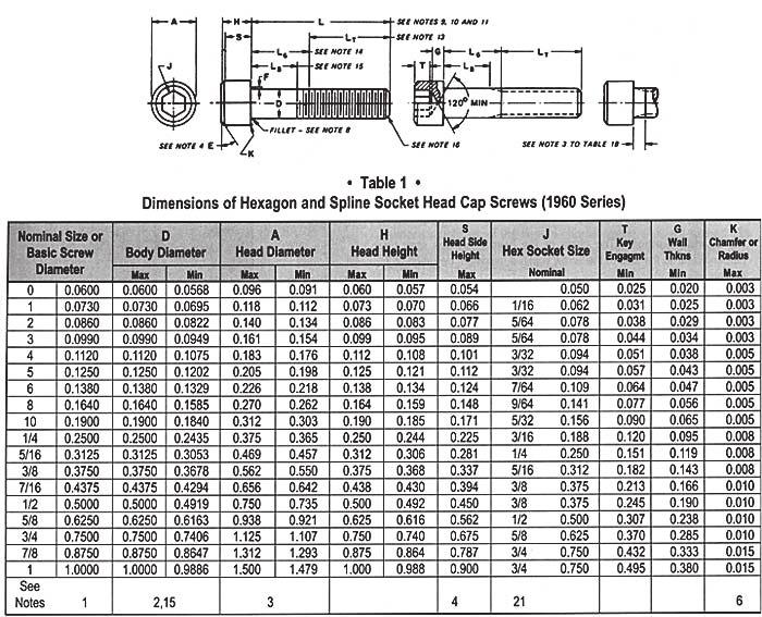
18 Appendix A Fastener Head Dimension Tables The following tables given the head dimensions for various types of machine and cap screws. They are helpful in specifying counterbore and countersink sizes for callouts. More complete tables may be found in Mechanical Design Handbooks and Mechanical drawing texts. Nominal Diameter F (across flats) G (across points) H (head height) 1/4 (0.2500) /32 5/16 (0.3125) /64 3/8 (0.3750) /64 7/16 (0.4375) /32 1/2 (0.5000) /16 9/16 (0.5625) /64 5/8 (0.6250) /64 3/4 (0.7500) /32 7/8 (0.8750) /64 1 (1.0000) /64 1 1/8 (1.1250) /16 1 1/4 (1.2500) /32 1 3/8 (1.3750) /32 1 1/2 (1.5000) /16 R (fillet radius) 18
19 19
20 20


21 Machine Screws Head Dimensions Head Dimension Tables Courtesy of Smith Fastener Round Head Machine Screws Slotted Phillips Nominal Size Head Dimensions for Round Head Machine Screws - ANSI B A H J T M G N Head Diameter Dimensions of Recess Height of Head Slot Width Slot Depth Diameter Depth Width Max Min Max Min Max Min Max Min Max Min Max Min / / / / Phillips Driver Size 21


22 Fillister Head Machine Screws Nominal Size Head Dimensions for Fillister Head Machine Screws - ANSI B A H O J T M G N Head Head Height Dimensions of Recess Slot Width Slot Depth Diameter Side Height Total Height Diameter Depth Width Max Min Max Min Max Min Max Min Max Min Max Min Max Min / / / Phillips Driver Size 22


23 Flat Head Machine Screws Nominal Size Head Dimensions for 82 Flat Head Machine Screws - ANSI B A H J T M R N F G Head Dimensions * Slot Dimensions Recess Dimensions Diameter Height Width Depth Dia Depth Width Protrusion Above Gaging Diameter Max Min Max Min Max Min Max Min Ref Ref Ref Max Min Gaging Diameter / / / / * Edge of head may be rounded or flat. Phillips Driver Size 23

24 Oval Head Machine Screws Nominal Size Head Dimensions for Oval Head Machine Screws - ANSI B A H O J T M R N F G Head Head Height Slot Dimensions Recess Dimensions Diameter Side Total Width Depth Dia Depth Width Protrusion Above Gaging Diameter Max Min Max Max Max Min Max Min Rew Ref Ref Max Min Gaging Diameter / / / / / Phillips Driver Size 24


25 Hex Head Machine Screws Nominal Size Head Dimensions Hex Head and Hex Washer Head Machine Screws - ANSI B A W H F U J T Width Across Flats Width Across Corners Head Height Washer Diameter Washer Thickness Slot Width Slot Depth Max Min Min Max Min Max Min Max Min Max Min Max Min / / / /
26 Metric Cap Screws Notes: All linear dimensions in millimeters The dimensions are generally in accordance with BS EN ISO 4762 BS & BS 4168 Socket Head Cap Screws (Metric) Nominal Thread. Hex Socket Size Body diameter and Head height Head Dia Soc. length Size Pitch Max Min Max Min M M M M M M M M M M
27 Flat Head Cap Screws (Metric) Nominal Thread Hex Socket Max Cone Head Soc. Head Dia size Pitch Size Dia Height length D J A 1 A_max A_Min H K M ,0 6,72 6,00 5,82 1,86 1,05 M ,5 8,96 8,00 7,78 2,48 1,49 M ,0 11,2 10,00 9,78 3,1 1,86 M ,0 13,44 12,00 11,75 3,72 2,16 M ,0 17,92 16,00 15,73 4,96 2,85 M ,0 22,4 20,00 19,67 6,2 3,60 M ,0 26,88 24,00 23,67 7,44 4,35 M ,0 33,6 32,00 29,67 8,8 4,89 M ,0 40,32 40,00 35,61 10,16 5,49 27
28 Appendix B Recommended Fastener Torques (from Recommended Torque Size Grade 5 Grade S/S Bronze Brass Coarse Fine Coarse Fine Coarse Fine Coarse Fine Coarse Fine #4* #6* #8* #10* / / / / / / / / / * Sizes from 4 to 10 are in in.-lbs. Sizes from 1/4 up are in Ft. -lbs. 28
29 Appendix C Bolt Grade Markings and Strength Chart (Table from Head Markings Grade or Class Material Nominal Size Range (Inches) American Proof Load (psi) Mechanical Properties Minimum Yield Strength (psi) Minimum Tensile Strength (psi) No Markings 3 Radial Lines 6 Radial Lines Stainless markings vary. Most stainless is nonmagnetic Grade 2 Grade 5 Grade Stainless Low or 1/4 thru 3/4 55,000 57,000 74,000 Medium Carbon Steel Over 3/4 thru 1-1/2 33,000 36,000 60,000 Medium Carbon Steel, Quenched and Tempered Medium Carbon Alloy Steel, Quenched and Tempered Steel alloy with 17-19% Chromium and 8-13% Nickel 1/4 thru 1 85,000 92, ,000 Over 1 thru 1-1/2 1/4 thru 1-1/2 1/4 thru 5/8 74,000 81, , , , ,000 80,000 90, , ,000 3/4 thru 1 100,000 45,000 70,000 80,000 Above 1 90,000 Metric 29
30 8.8 Class 8.8 Medium Carbon Steel, Quenched and Tempered All Sizes thru 1-1/2 85,000 92, , Class 10.9 Alloy Steel, Quenched and Tempered All Sizes thru 1-1/2 120, , ,000 Stainless markings vary. Most stainless is nonmagnetic A-2 Stainless Steel alloy with 17-19% Chromium and 8-13% Nickel 1/4 thru 5/8 80,000 90, , ,000 3/4 thru 1 100,000 45,000 70,000 80,000 Above 1 90,000 Tensile Strength: The maximum load in tension (pulling apart) which a material can withstand before breaking or fracturing. Yield Strength: The maximum load at which a material exhibits a specific permanent deformation Proof Load: An axial tensile load which the product must withstand without evidence of any permanent set. ISO metric fastener material strength property classes (grades). ISO metric fastener material property classes (grades) should be used. For example, fastener material ISO property class 5.8 means nominal (minimum) tensile ultimate strength 500 MPa and nominal (minimum) tensile yield strength 0.8 times tensile ultimate strength or 0.8(500) = 400 MPa. (In a few cases, the actual tensile ultimate strength may be approximately 20 MPa higher than nominal tensile ultimate strength indicated via the nominal property class code. Consult Table 10, below, for exact values.) Many anchor bolts (L, J, and U bolts, and threaded rod) are made from low carbon steel grades, such as ISO classes 4.6, 4.8, and
31 Appendix D Letter and Number Decimal Equivalents No. Size of No. in Decimals No. NUMBER DRILL SIZES Size of No. in Decimals No. Size of No. in Decimals No. Size of No. in Decimals
32 LETTER DRILL SIZE A N B O C P D Q E R F S G T H U I V J W K X L Y M Z
Engineering Design Representation. Use of 2D drawing format: Typical Design Annotation. Standardization. Extracted drawings. General dimensions
 Engineering Design Representation Some elements of design representation not easily conveyed through model alone. Many are notational in nature. Examples are: Thread specifications Surface finishes Surface
UNIT 9b: SCREW FASTENERS Introduction Functions Screw Features Elements Terms of a Thread Profile
 UNIT 9b: SCREW FASTENERS Introduction A mechanical screw is a cylinder or cone that has a helical ridge called a thread. A helix has one or more turns, so a screw can have several turns. If the helix is
1/2/2016. Lecture Slides. Screws, Fasteners, and the Design of Nonpermanent Joints. Reasons for Non-permanent Fasteners
 Lecture Slides Screws, Fasteners, and the Design of Nonpermanent Joints Reasons for Non-permanent Fasteners Field assembly Disassembly Maintenance Adjustment 1 Introduction There are two distinct uses
Sockets. Dimensions; Mechanical & Performance Requirements. Socket Head Cap Screws Body & Grip Lengths - Socket Cap Screws...
 imensions; Mechanical & Performance Requirements Socket Head Cap Screws... 2-4 Body & Grip Lengths - Socket Cap Screws... 5-6 Low Head Socket Cap Screws... 7 Button Head Socket Cap Screws... 8 Flat Head
METRIC FASTENERS 1520 METRIC FASTENERS
 1520 METRIC FASTENERS METRIC FASTENERS A number of American National Standards covering metric bolts, screws, nuts, and washers have been established in cooperation with the Department of Defense in such
CH # 8. Two rectangular metal pieces, the aim is to join them
 CH # 8 Screws, Fasteners, and the Design of Non-permanent Joints Department of Mechanical Engineering King Saud University Two rectangular metal pieces, the aim is to join them How this can be done? Function
SCREW THREADS. = minor diameter. d 3. d 2. = pitch diameter
 ISO : 6 Part 2 DIN : Part /20 Metric (ISO) screw thread, coarse series -M- T-00 T-002 for M to incl. M,4, fit H/6h The bold lines indicate the maximum material profiles. The maximum material profile of
Chapter Tests and Problems
 Chapter Tests and Problems Chapter 11 Fasteners and Springs Test INSTRUCTIONS Answer the questions with short, complete statements or drawings as needed. QUESTIONS Define the screw thread terms given in
Fasteners. Bolts. NAPA FastTrack Counter Sales Training Fasteners Page 1. Figure 1. Typical Measurements for a Bolt or Hex Head Cap Screw
 Fasteners Many types and sizes of fasteners are used in the automotive industry. Each fastener is designed for a specific purpose and condition. One of the most commonly used type of fastener is the threaded
Dimensioning. Dimensions: Are required on detail drawings. Provide the shape, size and location description: ASME Dimensioning Standards
 Dimensioning Dimensions: Are required on detail drawings. Provide the shape, size and location description: - Size dimensions - Location dimensions - Notes Local notes (specific notes) General notes ASME
FASTENERS. Aylin YENİLMEZ GÜRKÖK
 FASTENERS Aylin YENİLMEZ GÜRKÖK FASTENERS A fastener is a hardware device that mechanically joins or affixes two or more objects together. Welding, Soldering, Nuts & Bolts, Washers, Screws, Clips, Clamps,
Mechanical joints. Major diameter Mean diameter Minor diameter Pitch p chamfer. Root Crest. Thread angle 2a. Dr. Salah Gasim Ahmed YIC 1
 Screw fasteners Helical threads screws are an extremely important mechanical invention. It is the basis of power screws (which change angular motion to linear motion) and threaded fasteners such as bolts,
MATERIAL AND EQUIPMENT STANDARD FOR METRIC TYPE FASTENERS (SCREWS, BOLTS, STUDS, NUTS AND WASHERS) ORIGINAL EDITION DEC. 1997
 ORIGINAL EDITION DEC. 1997") MATERIAL AND EQUIPMENT STANDARD FOR METRIC TYPE FASTENERS (SCREWS, BOLTS, STUDS, NUTS AND WASHERS) ORIGINAL EDITION DEC. 1997 This Standard is the property of Iranian Ministry of Petroleum. All rights
MATERIAL AND EQUIPMENT STANDARD FOR METRIC TYPE FASTENERS (SCREWS, BOLTS, STUDS, NUTS AND WASHERS) ORIGINAL EDITION DEC. 1997 This Standard is the property of Iranian Ministry of Petroleum. All rights
c. Pins, bolts, and retaining rings b. Washers, locking nuts, and rivets
 62 20 HW 8: Fasteners / Force, Pressure, Density Mechanical Systems DUE Mon, 11/21/16 Start of class Check link on website for helpful fastener information Please use a scantron. Material is based primarily
Geometric dimensioning & tolerancing (Part 1) KCEC 1101
 KCEC 1101") Geometric dimensioning & tolerancing (Part 1) KCEC 1101 Introduction Before an object can be built, complete information about both the size and shape of the object must be available. The exact shape of
Geometric dimensioning & tolerancing (Part 1) KCEC 1101 Introduction Before an object can be built, complete information about both the size and shape of the object must be available. The exact shape of
Comparable ISO Standard. Date of current standard/modified
 Title Standard All-metal prevailing torque All-metal prevailing torque EN ISO EN ISO Comparable ISO Standard Date of current standard/modified 980 7042 27042 7042 1998-02 980 10513 30513 10513 1998-02
Chapter 2: Dimensioning Basic Topics Advanced Topics Exercises
 Chapter 2: Dimensioning Basic Topics Advanced Topics Exercises Dimensioning: Basic Topics Summary 2-1) Detailed Drawings 2-2) Learning to Dimension 2-3) Dimension Appearance and Techniques. 2-4) Dimensioning
THE GATE COACHAll Rights Reserved 28, Jia Sarai N.Delhi ,-9998
 1 P a g e 1 DESIGN AGAINST STATIC AND FLUCTUATING LOADS 2 SHAFT, KEYS AND COUPLINGS CONTENTS Introduction 6 Factor of safety 6 Stress concentration 7 Stress concentration factors 8 Reduction of stress
Chapter 7. Fasteners
 Chapter 7 Fasteners LEARNING OBJECTIVES After studying this chapter, students will be able to: Identify several types of fasteners. Explain why inch-based fasteners are not interchangeable with metric-based
Fasteners Table of Contents
 EML2322L Design & Manufacturing Laboratory Fasteners Table of Contents I. Copyright Notice II. Why Care? 1. Definitions 2. Common Fastener Types 3. Fastener Nomenclature 4. Fastener Thread Types 5. Rolled
Precision Manufacturing
 Precision Manufacturing 216 North Main Street. Freeport, NY 11520 Phone: 888-260-7466 / Fax: 516-771-6444 sales@ondrivesus.com www.ondrivesus.com Know Linear Your Shaft Shoulder Supports Screws By Dennis
the same information given in two different 1. Dimensions should NOT be duplicated, or Dimension Guidelines Incorrect ways.
 Dimension Guidelines 1. Dimensions should NOT be duplicated, or the same information given in two different ways. Incorrect 1. Dimensions should NOT be duplicated, or the same information given in two
ENGINEERING GRAPHICS ESSENTIALS. (A Text and Lecture Aid) Second Edition. Kirstie Plantenberg University of Detroit Mercy SDC PUBLICATIONS
 Second Edition. Kirstie Plantenberg University of Detroit Mercy SDC PUBLICATIONS") ENGINEERING GRAPHICS ESSENTIALS (A Text and Lecture Aid) Second Edition Kirstie Plantenberg University of Detroit Mercy SDC PUBLICATIONS Schroff Development Corporation www.schroff.com www.schroff-europe.com
ENGINEERING GRAPHICS ESSENTIALS (A Text and Lecture Aid) Second Edition Kirstie Plantenberg University of Detroit Mercy SDC PUBLICATIONS Schroff Development Corporation www.schroff.com www.schroff-europe.com
Technical Specifications Guide For Fasteners
 fastrite_2011_fut.ai 8/4/11 4:29:01 PM Technical Specifications Guide For Fasteners C M Y CM MY CY CMY K Important Disclaimer All of the information provided in this publication is intended for reference
TECH SHEET PEM - REF / AXIAL THREAD CLEARANCE. SUBJECT: Method for providing adequate axial thread clearance
 SUBJECT: Method for providing adequate axial thread clearance In our long history of working with customers in the application of our self-clinching nuts, PennEngineering has seen numerous instances of
BOLTS AND NUTS Square Bolts( Table 1 ) Hex Nuts ( Table 7 ) Heavy Hex Nuts (Table 7) Heavy Hex Structural Bolts ( Table 2 )
 Hex Nuts ( Table 7 ) Heavy Hex Nuts (Table 7) Heavy Hex Structural Bolts ( Table 2 )") BOLTS AND NUTS 1493 An externally threaded fastener that must be assembled with a nut to perform its intended service is a bolt. (Example: heavy hex structural bolt.) An externally threaded fastener that
BOLTS AND NUTS 1493 An externally threaded fastener that must be assembled with a nut to perform its intended service is a bolt. (Example: heavy hex structural bolt.) An externally threaded fastener that
MECH 344/M Machine Element Design
 1 MECH 344/M Machine Element Design Time: M 14:45-17:30 Lecture 6 Contents of today's lecture Introduction Multitude of fasteners are available raging from nuts and bots to different varieties. Only a
TAPTITE 2000 Fasteners
 TAPTITE 2000 Fasteners Unique Design Increases Performance TAPTITE 2000 fasteners are designed to provide the benefits of previous TAPTITE fastener products with an innovative new thread design the Radius
CIRRUS AIRPLANE MAINTENANCE MANUAL
 FASTENER AND HARDWARE GENERAL REQUIREMENTS 1. DESCRIPTION This section contains general requirements for common hardware installation. Covered are selection and installation of cotter pins, installation
Fasteners. Fastener. Chapter 18
 Fasteners Chapter 18 Material taken from Mott, 2003, Machine Elements in Mechanical Design Fastener A fastener is any device used to connect or join two or more components. The most common are threaded
Fastener Basics. Common Fastener Types. Fastener Materials. Grade / Class and Fastener Strength
 Fastener Basics Common Fastener Types Fastener Grade (US) or Class (metric) refers to the mechanical properties of the fastener material. Generally, a higher number indicates a stronger, more hardened
Interference Fits Interference Fits Reference Lecture 15 Notes
 Interference Fits Interference Fits Hole is undersized and part is heated to allow it to slide over shaft. Compressive interface pressure develops when part cools. Reference Lecture 15 Notes. Keys and
ERECTION & CONSTRUCTION
 ERECTION & CONSTRUCTION High Strength Structural Bolting Author: Clark Hyland Affiliation: Steel Construction New Zealand Inc. Date: 24 th August 2007 Ref.: Key Words High Strength Bolts; Property Class
Engineering Guide Inch & Metric
 Engineering Guide Inch & Metric A comprehensive catalog of UNBRAKO socket screws and related products In this catalog you will find complete information about UNBRAKO socket screws and such related products
TAPS AND THREADING DIES
 872 TAPS AN THRAING IS TAPS AN THRAING IS General dimensions and tap markings given in the ASM/ANSI Standard B94.9-1987 for straight fluted taps, spiral pointed taps, spiral pointed only taps, spiral fluted
LANDMARK UNIVERSITY, OMU-ARAN
 LANDMARK UNIVERSITY, OMU-ARAN LECTURE NOTE: DRILLING. COLLEGE: COLLEGE OF SCIENCE AND ENGINEERING DEPARTMENT: MECHANICAL ENGINEERING PROGRAMME: MECHANICAL ENGINEERING ENGR. ALIYU, S.J Course code: MCE
COMMON WRENCHES INTRODUCTION
 COMMON WRENCHES INTRODUCTION A wrench is a hand tool used to provide grip and mechanical advantage in applying torque to turn objects usually nuts and bolts. Wrenches allow us to use less force to rotate
The Engineer s Guide to Identifying Lead Screw Thread Forms
 The Engineer s Guide to Identifying Lead Screw Thread Forms Thread Forms There are hundreds of different thread forms that have been designed over several decades. There are only a few specific thread
Special Thumb Screw Order Form
 Special Thumb Screw Order Form QUOTE FOR: ORDER FOR: Name: Company: Address: QUANTITY: Phone #: City: State: Zip: Email Address: FILL IN YOUR DIMENSIONS write directly over light blue type* write clearly
AIRCRAFT HARDWARE What You Need To Know By Ron Alexander
 Page 1 of 6 AIRCRAFT CONSTRUCTION An Article Series by Ron Alexander AIRCRAFT HARDWARE What You Need To Know By Ron Alexander The quality of our workmanship in building an airplane is very important. We
High Tensile Steel Black Self-Colour Hexagon Socket Cap Head Screws: Metric Thread
 Datasheet RS Stock No: 529703 High Tensile Steel Black Self-Colour Hexagon Socket Cap Head Screws: Metric Thread Socket caps have a small cylindrical head with tall vertical sides giving them space-saving
SURFACE VEHICLE STANDARD
 400 Commonwealth Drive, Warrendale, PA 15096-0001 SURFACE VEHICLE STANDARD J429 Issued 1949-01 Revised 1999-01 REV. JAN1999 Submitted for recognition as an American National Standard Superseding J429 MAY1998
MECHANICAL ASSEMBLY John Wiley & Sons, Inc. M. P. Groover, Fundamentals of Modern Manufacturing 2/e
 MECHANICAL ASSEMBLY Threaded Fasteners Rivets and Eyelets Assembly Methods Based on Interference Fits Other Mechanical Fastening Methods Molding Inserts and Integral Fasteners Design for Assembly Mechanical
TECH SHEET PEM - REF / TESTING CLINCH PERFORMANCE. SUBJECT: Testing clinch performance of self-clinching fasteners.
 PEM - REF / TESTING CLINCH PERFORMANCE SUBJECT: Testing clinch performance of self-clinching fasteners. A self-clinching fastener s performance can be divided into two major types. The first is self-clinching
Fastener Basics. Common Fastener Types. Fastener Materials. Grade / Class and Fastener Strength
 Fastener Basics Common Fastener Types Fastener Grade (US) or Class (metric) refers to the mechanical properties of the fastener material. Generally, a higher number indicates a stronger, more hardened
Geometric Dimensioning and Tolerancing
 Geometric Dimensioning and Tolerancing (Known as GDT) What is GDT Helps ensure interchangeability of parts. Use is dictated by function and relationship of the part feature. It does not take the place
C H A P T E R E L E V E N
 DIMENSIONING C H A P T E R E L E V E N Giesecke, Hill, Spencer, Dygdon, Novak, Lockhart, Goodman 1 OBJECTIVES 1. Use conventional dimensioning techniques to describe size and shape accurately on an engineering
DFTG-1305 Technical Drafting Prof. Francis Ha
 DFTG-1305 Technical Drafting Prof. Francis Ha Session 5 Dimensioning Geisecke s textbook: 14 th Ed. Chapter 10 p. 362 15 th Ed. Chapter 11 p. 502 Update: 17-0508 Dimensioning Part 1 of 2 Dimensioning Summary
Air Cooled Engine Technology. Roth 9 th Ch 3 Fasteners & Sealing Pages 45 65
 Roth 9 th Ch 3 Fasteners & Sealing Pages 45 65 1. Engine & equipment can be common or can be designed to perform specific functions. Fasteners Options Features 2. The of a fastener is actually an inclined
ISO INTERNATIONAL STANDARD. Fasteners Torque/clamp force testing. Éléments de fixation Essais couple/tension. First edition
 Provläsningsexemplar / Preview INTERNATIONAL STANDARD ISO 16047 First edition 2005-02-01 Fasteners Torque/clamp force testing Éléments de fixation Essais couple/tension Reference number ISO 16047:2005(E)
45PC. TAP AND DIE SET
 Model # 7560 7561 45PC. TAP AND DIE SET OPERATOR S MANUAL STORE THIS MANUAL IN A SAFE PLACE FOR FUTURE REFERENCE Wear eye protection Use proper lubrication WARNING: FOR HAND CUTTING APPLICATIONS ONLY.
Screws. Introduction. 1. Nuts, bolts and screws used to clamp things together. Screws are used for two purposes:
 Screws Introduction Screws are used for two purposes: 1. To clamp things together. 2. To control motion. 1. Nuts, bolts and screws used to clamp things together. Nuts, bolts and screws that are used for
OUR QUALITY POLICY VISION MISSION
 AUSTENITE FASTENERS PVT.LTD. A unique name in fasteners line has come long way since its taking over Krishna Engineering Company which was established in 1999. The company has it is manufacturing plant
Various other types of drilling machines are available for specialized jobs. These may be portable, bench type, multiple spindle, gang, multiple
 Drilling The process of making holes is known as drilling and generally drilling machines are used to produce the holes. Drilling is an extensively used process by which blind or though holes are originated
01 FASTENERS JULY FASTENERS 1
 01 FASTENERS 4 Bolts 22 Socket Screws 30 Nuts 39 Washers 53 Screws 72 Threaded Rods & Studs 73 Rivets, Rivnuts & Accessories 82 Retaining Rings 84 Pins, Links, & Sleeves 91 Key Stock & Assortments 90 Anchors
Unit4 31. UnitS 39. Unit 6 47
 Preface..................... xi About the Author......... xiii Acknowledgments... xiv Unit 1 1 Bases for Interpreting Drawings........ I Visible Lines............. 3 Lettering on Drawings... 3 Sketching...
Fastener Type Chart. Fastener Categories. Sheet Metal Screws Fully threaded screws with a point for use in sheet metal. Abbreviated SMS.
 Fastener Categories Wood Screws Machine Screws Thread Cutting Machine Screws Screws with a smooth shank and tapered point for use in wood. Abbreviated WS. Screws with threads for use with a nut or tapped
TECHNICAL DESIGN II (546)
") DESCRIPTION The second in a sequence of courses that prepares individuals with an emphasis in developing technical knowledge and skills to develop working drawings in support of mechanical and industrial
DESCRIPTION The second in a sequence of courses that prepares individuals with an emphasis in developing technical knowledge and skills to develop working drawings in support of mechanical and industrial
OWNER: POSITION AUTHOR: POSITION Dan Boettcher Director of Engineering Richard Richardson Vice-Dir of Engineering
 KRESS CORPORATION ENGINEERING Design of Thru and Threaded Holes Standard DOC ID 095007 REVISION A TYPE PORTAL OWNER: POSITION AUTHOR: POSITION Dan Boettcher Director of Engineering Richard Richardson Vice-Dir
The Ensat self-tapping threaded insert...
 The nsat self-tapping threaded insert... nsat is a self-tapping threaded insert with external and internal thread, cutting slots or cutting bores. A continuous process of further development has brought
Trade of Toolmaking Module 1: Induction & Bench Fitting Unit 4: Hole Tapping Phase 2
 Trade of Toolmaking Module 1: Induction & Bench Fitting Unit 4: Hole Tapping Phase 2 Published by SOLAS 2014 Unit 4 1 Table of Contents Document Release History... 3 Unit Objective... 4 Introduction...
RIVETS AND THREADED INSERTS
 RIVETS AND THREADED INSERTS Tri-Clamp, Multi-Grip, Dome Head and Stainless Steel Rivets Multi-Grip Rivets Adapt to All Material Types and Thicknesses Threaded Inserts Install Threads Into Blind Areas and
AN, MS, NAS Bolts. AN3 20 bolts are identified by a multi-part code:
 AN, MS, NAS Bolts Most bolts used in aircraft structures are either (a) general-purpose, (b) internal-wrenching or (c) close-tolerance AN, NAS, or MS bolts. Design specifications are available in MIL-HDBK-5,
THREAD CUTTING & FORMING
 THREAD CUTTING & FORMING Threading, Thread Cutting and Thread Rolling: Machining Threads on External Diameters (shafts) Tapping: Machining Threads on Internal Diameters (holes) Size: Watch to 10 shafts
HARDLOCK NUT RIM & HARDLOCK NUT BASIC
 1 Clamp Load [kn] FEATURES OF HARDLOCK NUT Reusable without reduction in performance! Full torque management and completely fastened even with ZERO (0) clamp load! Available in various materials and surface
Glossary of Terms. Angularity: The angle between the axes of two fastener surfaces.
 Glossary of Terms Allowance: An intentional difference between the material limits of mating parts, either in the minimum clearance or maximum interference between the parts. Angularity: The angle between
Dimensioning 2-4) Dimensioning and Locating Simple Features
 Dimensioning and Locating Simple Features") Dimensioning 2-4) Dimensioning and Locating Simple Features Dimensioning Features a) A circle is dimensioned by its diameter and an arc by its radius using a leader line and a note. Exercise 2-6 Circular
Dimensioning 2-4) Dimensioning and Locating Simple Features Dimensioning Features a) A circle is dimensioned by its diameter and an arc by its radius using a leader line and a note. Exercise 2-6 Circular
AUDAS. Tel: Fax: No.259 Baichi north Rd.Haiyan.Zhejiang.
 Standard State SECTION A : SCREW THREAD Basic elements of screw thread design ANSI/ASME B1.7M Nomenclature.Definitions and letter symbols for screw thread ASME B1.1 Unified inch screw thread ( UN and UNF
( This link will provide you with a list of all ISO-6983 G-Codes
 CUSTOM HAZARDS CUSTOM HAZARDS CUSTOM HAZARDS In this lesson I am going to explain how to circle interpolate a 1/8-27 NPT with a formed thread E-Mill using G-Code on a vertical mill. I have provided the
Hubble GOTO Installation Instruction (1.3, 04/30/2014)
") Hubble GOTO Installation Instruction (1.3, 04/30/2014) 1. Preparation... 1 1.1 Tools required... 1 1.2 AZ GOTO Drive Parts List...1 1.3 ALT GOTO Drive Parts List... 1 2. The Azimuth motor drive installation...2
Hubble GOTO Installation Instruction (1.3, 04/30/2014) 1. Preparation... 1 1.1 Tools required... 1 1.2 AZ GOTO Drive Parts List...1 1.3 ALT GOTO Drive Parts List... 1 2. The Azimuth motor drive installation...2
3. ISO information on technical standardisation changeover to ISO
 3. ISO information on technical standardisation changeover to ISO 3.1 Code Technical standardisation is work of harmonisation in the technical field that is carried out jointly by all interested parties.
SECTION 7. SAFETYING
 9/8/98 AC 43.13-1B SECTION 7. SAFETYING 7-122. GENERAL. The word safetying is a term universally used in the aircraft industry. Briefly, safetying is defined as: Securing by various means any nut, bolt,
FNW can handle all your hanger and fastener needs, all in one place. FNW products are sold exclusively at Ferguson.
 FASTENERS PIPE HANGERS, SUPPORTS & STRUT ACCESSORIES FNW can handle all your hanger and fastener needs, all in one place. FNW products are sold exclusively at Ferguson. Quick Reference Nuts Heavy Hex Nuts...4
ENGINEERING STANDARDS SECTION: D TOG-L-LOC V-LOC OVAL-LOC LANCE-N-LOC INFORMATION. Tog-L-Loc. How The Joining Process Works
 Tog-L-Loc Tog-L-Loc is a circular, leakproof joint formed by drawing the metals into a circular "cup'' and then expanding the diameter to form a 360 radial lock below the bottom sheet. How The Joining
Structural Bolting. Notice the Grade 5 has a much smaller head configuration and a shorter shank then the grade A325 structural bolt.
 Structural Bolting ASTM F3125/F3125M is a structural bolt specification covering inch and metric bolt grades. This specification contains 4 inch series bolting grades: A325, F1852, A490, and F2280. These
Installation Instructions. Installation Type
 Installation Instructions 800 & 8050 Slide Track Door Closers Non Hold Open & Hold Open Models Note: Hold open models are not permitted to be installed in Listed fire door assemblies. PULL SIDE MOUNTED
In troduction Product descriptions and product changes Standardization DIN ISO EN 5
 CONTENT In troduction 4 1. Product descriptions and product changes 5 2. Standardization 5 2.1 DIN 5 2.2 5 2.3 EN 5 3. Small slotted or cross recessed screws 6 3.1 DIN comparison of the dimensions of small
Threaded Fasteners 2. Shigley s Mechanical Engineering Design
 Threaded Fasteners 2 Bolted Joint Stiffnesses During bolt preload bolt is stretched members in grip are compressed When external load P is applied Bolt stretches further Members in grip uncompress some
Operating Instructions For Lockformer Button Punch Flanger
 Capacity: 20 to 28 Gauge Galvanize Operating Instructions For Lockformer Button Punch Flanger To satisfactorily form the 90º button punch flange on light gauge materials, it was necessary to form the metal
A Brief Introduction to Engineering Graphics. Will Durfee & Tim Kowalewski Department of Mechanical Engineering University of Minnesota
 A Brief Introduction to Engineering Graphics Will Durfee & Tim Kowalewski Department of Mechanical Engineering University of Minnesota Opening comments Engineering graphics is the method for documenting
Installation Instructions. Installation Type
 Installation Instructions 300 & 3050 Slide Track Door Closers Non Hold Open & Hold Open Models Note: Hold open models are not permitted to be installed in Listed fire door assemblies. PULL SIDE MOUNTED
ISO INFORMATION ON TECHNICAL STANDARDISATION CHANGEOVER TO ISO
 ISO INFORMATION ON TECHNICAL STANDARDISATION 3.1 Code Technical standardisation is work of harmonisation in the technical field that is carried out jointly by all interested parties. Its aim is to stipulate,
Thread Repair & Thread Protection
 Thread Repair & Thread Protection Screw Thread Inserts, Kits & Components for Industrial Maintenance, Repair and Overhaul Bulletin 998 C E R T I F I E D ISO 9001 AS 9100 TS 16949 ISO 14001 The HELI-COIL
Mechanical Drawing. Fig 5-1
 College of Engineering 1 Mechanical Drawing Mechanical Engineering Department Mechanical Drawing Lecture 5 Keys and keyways 5-1 Introduction A key, Fig. 5.1, is usually made from steel and is inserted
JCutting Tools aerospace
 JCutting Tools aerospace AppLIcations A286 Fasteners The new and improved Jarhook is the best available tap for A286 fasteners. During extensive testing the Jarhook surpassed all of the competition in
Geometric Boundaries
 Geometric Boundaries Interpretation and Application of Geometric Dimensioning and Tolerancing (Using the Customary Inch System) Based on ASME Y14.5M-1994 Written and Illustrated by Kelly L. Bramble Published
CHAPTER 10. JOINTS Detachable and Permanent Joints
 CHAPTER 10. JOINTS 10.1 Detachable and Permanent Joints The joints of parts in apparatus, assemblies and machines vary in designated purpose, design form, and technology of manufacture. Joints are classified
Balaji THE COMPANY MISSION
 82, GANGOTRI INDUSTRIAL ESTATE, OPP. PANCHRATNA ESTATE, NR. RAMOL OVER BRIDGE, VATVA-382445.(GUJARAT), INDIA. Website : www.balajifasteners.co.in E-mail : info@balajifasteners.co.in OUR QUALITY POLICY
ENGINEERING GRAPHICS ESSENTIALS
 ENGINEERING GRAPHICS ESSENTIALS with AutoCAD 2012 Instruction Introduction to AutoCAD Engineering Graphics Principles Hand Sketching Text and Independent Learning CD Independent Learning CD: A Comprehensive
Camcar Socket Screw Technical Manual
 Camcar Socket Screw Technical Manual Camcar Socket Screws Founded on Innovation and Technical Expertise The Camcar brand began in 1943, cold forming a component others said couldn't be made. From that
Swivel Hoist Ring RIGGING ACCESSORIES. Color coded to distinguish between UNC (Red) and Metric (Silver) thread types.
 and Metric (Silver) thread types.") RIGGING ACCESSORIES Color coded to distinguish between UNC (Red) and Metric (Silver) thread types. Available in UNC and Metric thread sizes. UNC threads available in sizes from 800 pounds to 100,000 pounds,
RIGGING ACCESSORIES Color coded to distinguish between UNC (Red) and Metric (Silver) thread types. Available in UNC and Metric thread sizes. UNC threads available in sizes from 800 pounds to 100,000 pounds,
Evaluation of In-Pavement Light Fixture Designs and Performance
 Evaluation of In-Pavement Light Fixture Designs and Performance Presented to: IES ALC Fall Technology Meeting By: Joseph Breen Date: Background In-Pavement Light Fixture Assemblies Utilize a Circle of
METRIC FA S T E N E R S
 METRIC FASTENERS CAP SCREWS & BOLTS DIN 603 Carriage Bolt, A2 SS DIN 603 Carriage Bolt, A4 SS DIN 931 Class 8.8 Hex Cap Screw, Steel Zinc DIN 931 Class 10.9 Hex Cap Screw, Plain Steel DIN 933 Class 8.8
Quill Stop V2 Installation Guide 11/16/2014
 Thank you for purchasing the Quill Stop for the Sieg X3 (Grizzly G0463) and SX3 (Grizzly G0619) mills. Your feedback is always appreciated. Please email questions and comments to gregpriest@cox.net. What
TECH SHEET PEM - REF / THREAD GALLING. SUBJECT: Root causes and guidelines to promote optimized fastener performance TECH SHEET
 PEM - REF / THREAD GALLING SUBJECT: Root causes and guidelines to promote optimized fastener performance Introduction Occasionally, users of our self-clinching fasteners encounter thread binding issues
Weld Screws, Weld Nuts, Clinch Studs
 Weld Screws, Weld Nuts, Clinch Studs imensions; Mechanical & Performance Requirements Weld Screws Top Projection Style... 2 ottom Projection Style... 3 Weld Nuts Single Projection... 4 Multiple Projection...
ROTARY TABLE OPERATION AND SERVICE MANUAL HORIZONTAL AND VERTICAL. Horizontal & Vertical. Rotary Table (HVRT) Tilting Rotary Table
 Tilting Rotary Table") Horizontal & Vertical Rotary Table (HVRT) OPERATION AND SERVICE MANUAL Tilting Rotary Table Horizontal & Vertical Rapid Indexer VERTICAL AND HORIZONTAL ROTARY TABLE This Horizontal & vertical table is
Horizontal & Vertical Rotary Table (HVRT) OPERATION AND SERVICE MANUAL Tilting Rotary Table Horizontal & Vertical Rapid Indexer VERTICAL AND HORIZONTAL ROTARY TABLE This Horizontal & vertical table is
ISO INTERNATIONAL STANDARD. Fasteners Torque/clamp force testing. Éléments de fixation Essais couple/tension. First edition
 INTERNATIONAL STANDARD ISO 16047 First edition 2005-02-01 Fasteners Torque/clamp force testing Éléments de fixation Essais couple/tension Reference number ISO 16047:2005(E) ISO 2005 PDF disclaimer This
Bolt Material Types and Grades 1- Bolts made of carbon steel and alloy steel: 4.6, 4.8, 5.6, 5.8, 6.8, 8.8, 10.9 Nuts made of carbon steel and alloy
 Bolt Material Types and Grades 1- Bolts made of carbon steel and alloy steel: 4.6, 4.8, 5.6, 5.8, 6.8, 8.8, 10.9 Nuts made of carbon steel and alloy steel: 4, 5, 6, 8, 10, 12 2- Bolts made of stainless
Dimensions Mechanical and Performance Requirements. Drop-In Anchors Hollow Wall, Steel Regular Style Drive Style...
 Dimensions Mechanical and Performance Requirements Drop-In Anchors... 257 Hollow Wall, Regular Style... 258 Drive Style... 259 Hollow Wall, Plastic Ribbed... 260 Conical, Light Duty... 261 Fluted, Light