Drawing & Design. Lecture 3. Lecturer: Dr. John Cheung
|
|
|
- Gyles Webb
- 5 years ago
- Views:
Transcription
1 MECH 313 Engineering Drawing & Design Lecture 3 Lecturer: Dr. John Cheung
2 Outline Limits and tolerances Fits and allowances Surface texture
3 Why ygive Tolerance? Manufacturing Practice is 6000 years old, While tolerancing is only 80 years old Because only then, they came to realize that exact dimensions and shapes cannot be attained What people thought were exact, have deviations, given the advanced metrology equipment that we have now Once, it is understood that the variations cannot be avoided, the best way is to limit the variations Tolerances are permissible variations in the specified form, size or location of individual features or a part from that shown on a drawing If 1.500±.004 is given, the part can be anywhere between to 1.504
4 Limits and tolerances In a same part different portions have different Accuracy Greater accuracy = greater costs and it is not needed to maintain high accuracy on all parts Accuracy is mainly high on assembled part so that they function properly
5 Limits and tolerances Key Concepts Actual Size - is the measured size Basic Size - of a dimension is the theoretical size from which h the limits it for that t dimension i are derived d by the application of the allowance and tolerance. Design Size - refers to the size from which the limits of size are derived by the application of tolerances. Limits of Size - are the maximum and minimum sizes permissible for a specific dimension. Nominal Size - is the designation used for the purpose of general identification.
6 Limits and tolerances Key Concepts Tolerance - The tolerance on a dimension is the total permissible variation in the size of a dimension. The tolerance is the difference between the limits of size. ±.004 Bilateral Tolerance - Variation is permitted in both directions from the specified dimension. Unilateral Tolerance - Variation is permitted in only one direction from the specified dimension. Maximum Material Size - The limit it of size of a feature that t results in the part containing the maximum amount of material. Thus it is the maximum limit of size for a shaft or an external feature, or the minimum limit of size for a hole or internal feature. MMC
7 Limits and tolerances Terminology
8 Limits and tolerances Tolerance Specification All dimensions require tolerance (except those identified as reference, max or min, or stock) - No critical areas. As specified limits of tolerances shown directly on the drawing for a specified dimension. As plus-and-minus tolerancing. Combining a dimension with a tolerance symbol class of fit. (Unit 8-6.)
9 Limits and tolerances Tolerance Specification In a general tolerance note, referring to all dimensions on the drawing for which tolerances are not otherwise specified. In the form of a note referring to specific dimensions. Tolerances on dimensions that locate features may be applied directly to the locating dimensions or by the positional tolerancing method described in Chap. 16. Tolerancing applicable to the control of form and run out, referred to as geometric tolerance, is covered in detail in Chap. 16.
. If placed in single line, low precedes the high and separated by a, e.g. Ø.252 -.")
10 Limits and tolerances Direct Tolerancing Methods Tolerance applied directly to dimension is expressed Limit Dimensioning Plus and Minus Tolerancing Limit Dimensioning - The high limit (max value) is placed above the low limit (min value). If placed in single line, low precedes the high and separated by a, e.g. Ø If high or low dimension has digits to the right of the decimal, both are expressed in same number of decimal places
11 Limits and tolerances Direct Tolerancing Methods Plus & Minus tolerancing Dimension is placed first followed by the ± expression of tolerance) Plus should be above the minus value) This can be divided further into Bilateral Tolerancing Unilateral Tolerancing
12 Limits and tolerances Metric Tolerancing Special case
13 Limits and tolerances Metric Tolerancing The dimension need not to be shown to the same number of decimal places as its tolerance. For example: When bilateral tolerancing is used, both the + and the values have the same number of decimal places, using 0s when necessary When unilateral tolerancing is used, and either the + and the value is nil, a single 0 is shown without the + or sign
14 Inch Tolerancing The dimension need to be shown to the same number of decimal places as its tolerance. For example:.500 ±.004 not.5 ±.004
15 Limits and tolerances General Tolerance Notes This simplifies the drawing and saves layout. For Example
16 Limits and tolerances Tolerance Accumulation It is important to consider the effect of each tolerance with respect to other tolerance Not to permit chain of tolerances to buildup cumulative tolerance between surfaces or points that have important relation to one another When position of surface is controlled by more than one tolerance, the tolerances are cumulative Tolerance accumulation in different dimensioning methods Chain dimensioning Datum dimensioning Direct dimensioning
17 Limits and tolerances Chain Dimensioning Maximum variation between any two features is equal to sum of tolerances on the intermediate distances. This results in greatest tolerance accumulation Accumulated tolerance between X and Y is ±0.08
18 Limits and tolerances Datum Dimensioning Maximum variation between any two features is equal to sum of tolerances on two dimensions from the datum to feature This results in lesser tolerance accumulation Accumulated tolerance between X and Y is ±0.04 (4.40 ±.04)
19 Limits and tolerances Direct Dimensioning Maximum variation between any two features is controlled by tolerance on the dimensions between features This results in least tolerance accumulation Accumulated tolerance between X and Y is ±0.02
20 Limits and tolerances Additional rules for dimensioning The engineering g intent must be clearly defined. Dimensions must be complete enough to describe the total geometry of each feature. Determining a shape by measuring its size on a drawing or by assuming a distance or size is not acceptable. Dimensions should be selected and arranged to avoid unsatisfactory accumulation of tolerances, to preclude more than one interpretation, and to ensure a proper fit between mating parts. The finished part should be defined without specifying manufacturing methods. Thus only the diameter of a hole is given, without indicating whether it is to be drilled, reamed, punched, or made by any other operation. Consultation. Dimensions must be selected to give required information directly.
21 Limits and tolerances Additional rules for dimensioning Dimensions should preferably be shown in true profile views and refer to visible outlines rather than to hidden lines. Drawings that illustrate part surfaces or center lines at right angles to each other, but without t an angular dimension, i are interpreted t as being 90 between these surfaces or center lines. Actual surfaces, axes, and center planes may vary within their specified tolerance of perpendicularity. it Dimension lines are placed outside the outline of the part and between the views unless the drawing may be simplified or clarified by doing otherwise. Dimension lines should be aligned, if practicable, and should be grouped for uniform appearance.
22 Fits and Allowances For assembled parts to function properly and to facilitate t interchangeable manufacturing, there is a necessity to permit only certain amount of tolerances and allowances between them Fits The fit between two mating parts is the relationship between them with respect to the amount of clearance or interference present when they are assembled. There are three basic types of fits: clearance, interference, and transition.
23 Fits and Allowances Fits Clearance Fit - A fit between mating parts having limits of size so prescribed that a clearance always results in assembly. Interference Fit - A fit between mating parts having limits of size so prescribed that an interference always results in assembly. Transition Fit - A fit between mating parts having limits of size so prescribed as to partially or wholly overlap, so that either a clearance or an interference may result in assembly.

24 Fits and Allowances Allowance is difference between maximum material limits of mating parts (minimum clearance is positive allowance,maximum interference is negative allowance). Basic Size - The size to which limits or deviations are assigned. The basic size is the same for both members of a fit. Deviation - The algebraic difference between a size and the corresponding basic size.

25 Fits and Allowances Allowance Upper Deviation The difference between the maximum limit of size and the corresponding basic size. Lower Deviation The difference between the minimum limit of size and the corresponding basic size. Tolerance The difference between the maximum and minimum size limits Tolerance Zone A zone representing the tolerance and its position in relation to the basic size. Fundamental Deviation The deviation closest to the basic size.
26 Fits and Allowances Description of Fits Running and Sliding Fits -A special type of clearance fit. These are intended to provide a similar running performance, with suitable lubrication allowance, throughout the range of sizes Locational Fits Intended to provide the location of mating parts. They may provide rigid or accurate location, as with interference fits, or some freedom of location, as with clearance fits. Accordingly, gy, they are divided into three groups: clearance, transition, and interference fits Locational clearance fits - are intended for parts that are normally stationary but that can be freely assembled or disassembled Snug fit for parts that require to be located with high accuracy Medium clearance for parts like ball, race and housing Loose fit for ease of freedom of assembly (example for fasteners)
27 Fits and Allowances Description of Fits Locational transition fits - are a compromise between clearance and interference fits when accuracy of location is important but a small amount of either clearance or interference is permissible Locational interference fits - are used when accuracy of location is of prime importance and for parts requiring rigidity and alignment with no special requirements for bore pressure not used for transmitting frictional loads from one part to another Drive or Force Fits a special type of interference fit, normally characterized by maintenance of constant bore pressures throughout the range of sizes. The difference between maximum and minimum values is small to maintain resulting pressure
28 Fits and Allowances Interchangeability of Parts Basis for mass production and low cost manufacturing Today it is possible to produce parts with 100% interchangeability No part can be produced to exact dimensions Machine variations, tool wear and human errors contribute to deviation Necessary to determine permissible clearance or interference to facilitate fit between parts Completely interchangeable assembly all mating parts are toleranced to permit assembly and proper function without need for machining or fitting at assembly Fitted assembly all mating parts are fabricated simultaneously or with respect to one another. Individual members of mating parts are not interchangeable Selected assembly all parts are mass produced but members of mating features are individually selected to provide required relationship with one another
29 Clearance fit
30 Transition fit
31 Interference Fit


32 Fits and Allowances Standard inch Fits Standard fits are designated to specify on design sketches with symbols They are not shown on shop drawings but actual limits of size are determined and shown RC Running and sliding fit LC Locational clearance fit LT Locational transition fit LN Locational interference fit FN Force or shrink fit The two letters and the number express complete fit the limits of size are given in appendix
33 Fits and Allowances Running and sliding Fits RC1 Precision Sliding Fit - This fit is intended for the accurate location of parts that must assemble without perceptible play, for example, for highprecision work such as gages. RC2 Sliding Fit - This fit is intended for accurate location, but with greater maximum clearance than class RC 1. Parts made to this fit move and turn easily but are not intended to run freely, and in the larger sizes may seize with small temperature changes. Note: LCI and LC2 locational clearance fits may also be used as sliding fits with greater tolerances. RC3 Precision Running Fit - This fit is about the closest fit that can be expected to run freely and is intended for precision work for oil-lubricated lubricated bearings at slow speeds and light journal pressures, but is not suitable where appreciable temperature differences are likely to be encountered.
34 Fits and Allowances Running and sliding Fits RC4 Close Running Fit - This fit is intended chiefly as a running fit for grease- or oil-lubricated bearings on accurate machinery with moderate surface speeds and journal pressures, where accurate location and minimum play are desired. RC5 and RC6 Medium Running Fits - These fits are intended for higher running speeds and/or where temperature variations are likely to be encountered. RC7 Free Running Fit - This fit is intended for use where accuracy is not essential and/or where large temperature variations are likely to be encountered. RC8 and RC9 Loose Running Fits - These fits are intended for use where materials made to commercial tolerances, such as cold-rolled shafting, or tubing, are involved.
35 Fits and Allowances Locational clearance Fits Locational clearance fits are intended for parts that are normally stationary but that can be freely assembled or disassembled. Snug fit medium clearance fit spigot for looser fasteners. LC1 to LC4 These fits have a minimum zero clearance LC5 and LC6 These fits have a small minimum clearance. Bolts LC7 and LC11 These fits have progressively larger clearances and tolerances and are useful for various loose clearances for the assembly of bolts and similar parts.
36 Fits and Allowances Locational Transition Fits Either a small amount of clearance or interference is permissible. Accuracy of location important. LT.1 and LT2 These fits average have a slight clearance, giving a light push hfit, and are intended dfor use where the maximum clearance must be less than for the LCI to LC3 fits. Assembly light pressure. LT3 and LT4 These fits average virtually no clearance and are for use where some interference can be tolerated, for example, to eliminate vibration. Inner bearing race, shaft key. LT5 and LT6 These fits average a slight interference, although appreciable assembly force will be required when extreme limits are encountered, and selective assembly may be desirable. Heavy key. Heavy duty, vibration.
37 Fits and Allowances Locational interference Fits Accuracy of location, but no transmitting of torque. LN1 and LN2 - These are light press fits, with very small minimum interference, suitable for parts such as dowel pins. LN3 - This is suitable as a heavy press fit in steel and brass, or a light press fit in more elastic materials and light alloys. LN4 to LN6 - Although LN4 can be used for permanent assembly of steel parts, primarily suited for elastic or plastic parts.
38 Fits and Allowances Force or shrink Fits Maintenance of constant pressure, variable in size small. FN1 Light Drive Fit - Requires light assembly pressure and produces more or less permanent assemblies. It is suitable for thin sections or long fits, or in cast iron external members. FN2 Medium Drive Fit - Suitable for ordinary steel parts or as a shrink fit on light sections. It is about the tightest fit that can be used with high-grade cast iron external members. FN3 Heavy Drive Fit - Suitable for heavier steel parts or as a shrink fit in medium sections. FN4 and FNS Force Fits - Suitable for parts that can be highly stressed and/or for shrink fits where the heavy ypressing forces required are impractical.
39 Fits and Allowances Basic Hole System In the basic hole system, which h is recommended d for general use, the basic size will be the design size for the hole, and the tolerance will be plus. The design size for the shaft will be the basic size minus the minimum clearance, or plus the maximum interference eg. (table 43 appendix A 26) An 1 RC7 fit, values of (hole tolerance),.0025 (min clearance), and (shaft tolerance) the limits will be Hole Ø Shaft Ø
40 Fits and Allowances Basic Shaft System Fits are sometimes required on a basic shaft system, especially when two or more fits are required on the same shaft. It is indicated (for design purposes) p with an S following the fit symbol RC7S. Table not available for inch fit. eg. An 1 RC7 fit, values of (hole tolerance),.0025 (min clearance), and (shaft tolerance) the limits will be Hole Ø Shaft Ø
41 Fits and Allowances
 International tolerance grades")
")

42 Fits and Allowances Preferred Metric Limits and Fits General terms hole and shaft can also be taken as space contained by two parallel faces of parts (width of slot or thickness of key) International tolerance grades (IT) establishes the magnitude of tolerance zone (amount of part variation Appendix table 40) There are 18 tolerance grades identified by IT as prefix Smaller the grade No, smaller the tolerance zone (more precise) 1-4 are very precise used for gage making and high precision work 5-16 represent progressive series suitable for cutting Grade 5 is most precise obtained by grinding and lapping and grade 16 is most coarse obtained by sawing
 Tolerance Symbol In metric system, the tolerance maybe indicated by a basic size and tolerance symbol")
43 Fits and Allowances Preferred Metric Limits and Fits A fundamental deviation establishes the position of the tolerance zone wrt to basic size. FD is expressed by tolerance position letters (upper case for internal and lower for external) Tolerance Symbol In metric system, the tolerance maybe indicated by a basic size and tolerance symbol Combination of IT grade and the position letter the symbol is established to define maximum and minimum clearance of the part Tolerance sizes are defined by basic size, followed by symbol composed of letter and number
44 Fits and Allowances Hole Basis System The basic size will be the design size for the hole eg. (table 48 appendix) A Φ25H8/f7 fit, hole basis clearance fit Minimum Maximum A Φ25H7/s6 fit, hole basis interference fit Minimum Maximum
45 Fits and Allowances Shaft Basis System Used when more than two fits are required on the same shaft. The basic size will be the maximum shaft size. for eg. (table 49 appendix) A Φ16 C11/h11 fit, shaft basis clearance fit

46 Fits and Allowances Type of Metric Fits Hole basis have FD of H on the hole, H11/C11 Shaft basis have FD of h on the shaft. C11/h11 Hole basis is preferred Three common fits in Metric (shown in figure)
47 Fits and Allowances Fit Symbol Fit is indicated by the basic size common to both components, followed by a symbol corresponding to each component, with internal preceding the external part symbol The limits of size for a hole having tolerance symbol 40H8 (table 41 and then table 48) 40 H8
 Ø39.")
 Method is first introduced d limit")
 When some experience")
 When system")
48 Fits and Allowances Fit Symbol limits of size for a shaft having tolerance symbol 40f7 (table 48) Ø Maximum limit Ø Minimum limit (A) Method is first introduced d limit it dimensions are specified and basic size & tolerance symbol identified as reference (B) When some experience gained basic size & tolerance symbol are specified and limit dimensions identified as reference (C) When system established only basic size & tolerance symbol are specified
49 Fits and Allowances Preferred Metric fits
50 Surface Texture Why Surface texture? Development of high speed machines with higher loading increases friction and wear To reduce friction (heat) and control wear, it becomes essential for the designer to accurately define surface finish for the manufacturers It is necessary to remove guesswork or opinion It is designers responsibility to specify right surface for maximizing performance and life at lowest cost The decision is based on design of similar parts, field data or engineering data with particular stress on Size and function of part Speed and direction of movement Operating condition Type of loading Size and function of part Physical characteristics of contact materials Type and amount of lubricant Contaminants and temperature
51 Surface Texture Why Surface texture? When a lubricant film needs to be maintained between two moving parts surface irregularities need to small so that they will not penetrate the film in sever operating conditions Bearings, journals, cylinder bores, piston pins, bushings etc. are some examples Surface finish is also important for accuracy and pressure retaining ability Fuel injectors, High-pressure demand smoothness and lack of waviness Surface finish is also important in dry friction (absence of lubricant) to control wear Tool bits, threading and stamping dies clutch plates and break drums
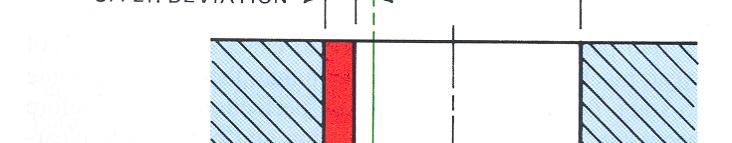
52 Surface texture
53 Surface Texture Surface texture characterisitcs Micro Inch or Micrometer is one millionth of an inch or meter respectively. ( ). For written specification or for mentioning in drawing it can be abbreviated as µin or µm respectively Roughness - Roughness consists of the finer irregularities in the surface texture, usually including those that result from the inherent action of the production process. These include traverse feed marks and other irregularities within the limits of the roughnesswidth cutoff.
54 Surface Texture Surface texture characterisitcs Roughness-Height g Value -Roughness-height g value is rated as the arithmetic average (AA) deviation expressed in micro inches or micrometers measured normal to the center line. The ISO and many European countries use the term CLA (center line average) in lieu of AA. Both have the same meaning. Roughness Spacing - Roughness spacing is the distance parallel to the nominal surface between successive peaks or ridges that constitute the predominant pattern of the roughness. Roughness spacing is rated in inches or millimeters.
55 Surface Texture Surface texture characterisitcs Roughness-Width Cutoff - The greatest spacing of repetitive surface irregularities is included in the measurement of average roughness height. Roughness-width cutoff is rated in inches or millimeters and must always be greater than the roughness width in order to obtain the total roughness-height rating. Waviness - Waviness is usually the most widely spaced of the surface texture components and normally is wider than the roughness-width cutoff. Lay - The direction of the predominant surface pattern, ordinarily determined by the production method used, is the lay. Flaws - Flaws are irregularities that occur at one place or at relatively infrequent or widely varying intervals in a surface.


56 Surface Texture Surface texture symbol Surface characteristics are mentioned in the drawing with help of symbols When only roughness is shown horizontal line is omitted Horizontal line is used to specify surface characteristics to the right of fthe symbol The point of the symbol should be on the surface The symbol always applies to entire or on extension to the surface unless specified otherwise and surface or a leader from not duplicated in other views the surface

57 Surface Texture Surface texture symbols If numerical values are there it should be upright so that the figures are readable from the bottom If numerical values are not there, the symbol can be positioned to be readable from the right side
58 Surface Texture Surface texture symbols Roughness is indicated to left of the long leg (the roughness grade number N values are shown in fig 8-7-7) If only one rating is given it is maximum value and anything less is acceptable If 2 numbers are given anything inbetween is acceptable and max is placed above min Similarly for waviness height and spacing. If minimum value is shown it is shown with MIN next to the number Lay symbols are shown in fig If roughness sampling length is not specified it is standard.03in or.8mm

59 Surface Texture Notes Lay symbols Notes relating to surface roughness can be local or general. Normally, a general note is used when a given roughness requirement applies to the whole part or the major portion. Any exceptions to the general note are given in a local note


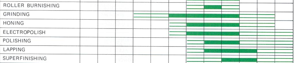

60 Roughness range for common production methods


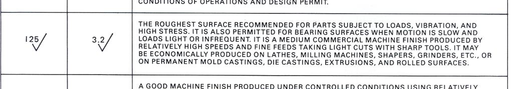
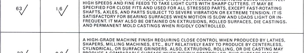
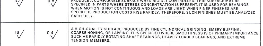
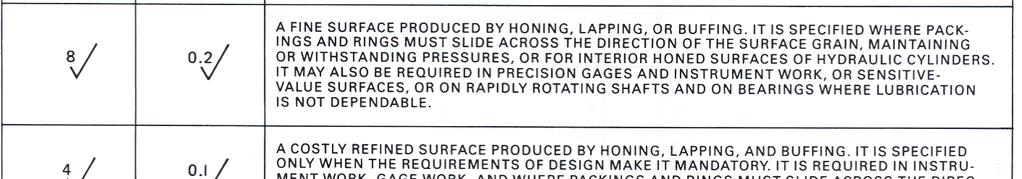
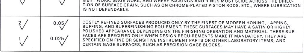
61 Typical surface Roughness height applications
62 Surface Texture Machined Surfaces While drawing for parts to be cast or forged, surfaces that require machining are identified. If all surfaces need to be machined a general note FINISH ALL OVER is used and symbols may be omitted When space is restricted the symbols can be shown on a extension line

63 Surface Texture Machined surfaces Machining symbols are not duplicated similar to dimensions Used on the view as the dimensions that give size and location of the concerned surfaces The symbols are placed on the surface or on the extension line locating the surface Figure shows the example of use of machining symbols


64 Surface Texture Machined surfaces Material removal allowance when amount material to be removed needs to indicated, it is done to the left of the symbol Material removal prohibited when it is needed to indicate that a surface is produced without material removal machining prohibited symbol is used
SYSTEM OF LIMITS, FITS, TOLERANCES AND GAUGING
 UNIT 2 SYSTEM OF LIMITS, FITS, TOLERANCES AND GAUGING Introduction Definition of limits Need for limit system Tolerance Tolerance dimensions ( system of writing tolerance) Relationship between Tolerance
ME 114 Engineering Drawing II
 ME 114 Engineering Drawing II FITS, TOLERANCES and SURFACE QUALITY MARKS Mechanical Engineering University of Gaziantep Dr. A. Tolga Bozdana Assistant Professor Tolerancing Tolerances are used to control
Tolerancing. Summary
 Tolerancing Summary Summary What will we learn We will learn about tolerancing and how important this technique is to mass production. Key points If a feature s size is toleranced, it is allowed to vary
Dimensioning. Dimensions: Are required on detail drawings. Provide the shape, size and location description: ASME Dimensioning Standards
 Dimensioning Dimensions: Are required on detail drawings. Provide the shape, size and location description: - Size dimensions - Location dimensions - Notes Local notes (specific notes) General notes ASME
: Fits and Tolerances
 Fits and Tolerances CONTENTS Why tolerances and fits are required? Due to the inevitable inaccuracy of manufacturing methods, a part cannot be made precisely to a given dimension, the difference between
Engineering drawing. Semester I/II Mechanical Engineering Department Technical University of Gdańsk. Lecture 8
 Engineering drawing Semester I/II Mechanical Engineering Department Technical University of Gdańsk Lecture 8 Representing Tolerance Values Tolerance is the total amount a dimension may vary and is the
Assembly of Machine Parts
 Machine Drawing Assembly of Machine Parts Temporary Permanent Fastening Keying Fitting Welding Riveting Interference fit Machine drawing is the indispensable communicating medium employed in industries,
Geometric Dimensioning and Tolerancing
 Geometric Dimensioning and Tolerancing (Known as GDT) What is GDT Helps ensure interchangeability of parts. Use is dictated by function and relationship of the part feature. It does not take the place
Test Answers and Exam Booklet. Geometric Tolerancing
 Test Answers and Exam Booklet Geometric Tolerancing iii Contents ANSWERS TO THE GEOMETRIC TOLERANCING TEST............. 1 Part 1. Questions Part 2. Calculations SAMPLE ANSWERS TO THE GEOMETRIC TOLERANCING
Unit4 31. UnitS 39. Unit 6 47
 Preface..................... xi About the Author......... xiii Acknowledgments... xiv Unit 1 1 Bases for Interpreting Drawings........ I Visible Lines............. 3 Lettering on Drawings... 3 Sketching...
Chapter 2: Dimensioning Basic Topics Advanced Topics Exercises
 Chapter 2: Dimensioning Basic Topics Advanced Topics Exercises Dimensioning: Basic Topics Summary 2-1) Detailed Drawings 2-2) Learning to Dimension 2-3) Dimension Appearance and Techniques. 2-4) Dimensioning
and mean roughness index R a of the micro-irregularities. Following are the definitions of the terms indicated in Fig. 16.1:
 It is not possible to achieve in practice, a geometrically ideal surface of a component and hence, production drawings of components must also contain information about the permissible surface conditions.
DRAFTING MANUAL. Dimensioning and Tolerancing Rules
 Page 1 1.0 General This section is in accordance with ASME Y14.5-2009 Dimensioning and Tolerancing. Note that Rule #1 is the only rule that is numbered in the 2009 standard. All of the other rules fall
IPE 381 Chapter:04 Limit, Fits and Tolerance
 IPE 381 Chapter:04 Limit, Fits and Tolerance Abdullah-Al-Mamun Lecturer, Dept. of IPE Outline Basics of Limit and Fit Interchangeable manufacturing Different types of fit Tolerance Tolerance Calculation
GEOMETRICAL TOLERANCING
 GEOMETRICAL TOLERANCING Introduction In a typical engineering design and production environment, the designer of a part rarely follows the design to the shop floor, and consequently the only means of communication
STEEL RULE. Stock TRY SQUARE
 FITTING INTRODUCTION Fitting consists of a handwork involved in fitting together components usually performed at a bench equipped with a vice and hand tools. The matting components have a close relation
Session 10 Dimensions, Fits and Tolerances for Assembly
 Session 10 Dimensions, Fits and Tolerances for Assembly Lecture delivered by Prof. M. N. Sudhindra Kumar Professor MSRSAS-Bangalore 1 Variations in Production It is necessary that the dimensions, shape
the same information given in two different 1. Dimensions should NOT be duplicated, or Dimension Guidelines Incorrect ways.
 Dimension Guidelines 1. Dimensions should NOT be duplicated, or the same information given in two different ways. Incorrect 1. Dimensions should NOT be duplicated, or the same information given in two
ENGINEERING GRAPHICS ESSENTIALS. (A Text and Lecture Aid) Second Edition. Kirstie Plantenberg University of Detroit Mercy SDC PUBLICATIONS
 Second Edition. Kirstie Plantenberg University of Detroit Mercy SDC PUBLICATIONS") ENGINEERING GRAPHICS ESSENTIALS (A Text and Lecture Aid) Second Edition Kirstie Plantenberg University of Detroit Mercy SDC PUBLICATIONS Schroff Development Corporation www.schroff.com www.schroff-europe.com
ENGINEERING GRAPHICS ESSENTIALS (A Text and Lecture Aid) Second Edition Kirstie Plantenberg University of Detroit Mercy SDC PUBLICATIONS Schroff Development Corporation www.schroff.com www.schroff-europe.com
TECHNICAL DESIGN II (546)
") DESCRIPTION The second in a sequence of courses that prepares individuals with an emphasis in developing technical knowledge and skills to develop working drawings in support of mechanical and industrial
DESCRIPTION The second in a sequence of courses that prepares individuals with an emphasis in developing technical knowledge and skills to develop working drawings in support of mechanical and industrial
BEARING AND TYPES OF BEARING
 BEARING AND TYPES OF BEARING In this article, you will learn about bearing and types of bearing. Generally, all types of machinery are provided with supports for rotating shafts, the supporting device
DFTG-1305 Technical Drafting Prof. Francis Ha
 DFTG-1305 Technical Drafting Prof. Francis Ha Session 5 Dimensioning Geisecke s textbook: 14 th Ed. Chapter 10 p. 362 15 th Ed. Chapter 11 p. 502 Update: 17-0508 Dimensioning Part 1 of 2 Dimensioning Summary
ROOP LAL Unit-6 Lathe (Turning) Mechanical Engineering Department
 Mechanical Engineering Department") Notes: Lathe (Turning) Basic Mechanical Engineering (Part B) 1 Introduction: In previous Lecture 2, we have seen that with the help of forging and casting processes, we can manufacture machine parts of
Notes: Lathe (Turning) Basic Mechanical Engineering (Part B) 1 Introduction: In previous Lecture 2, we have seen that with the help of forging and casting processes, we can manufacture machine parts of
Manufacturing Technician Training
 Mike McKinney / Jefferson College I. Objective: Developed to meet the industry demands and provide a six-week certification program to fast track individuals to secure a position in the manufacturing industry
1 st Subject: Types and Conventions of Dimensions and Notes
 Beginning Engineering Graphics 7 th Week Lecture Notes Instructor: Edward N. Locke Topic: Dimensions, Tolerances, Graphs and Charts 1 st Subject: Types and Conventions of Dimensions and Notes A. Definitions
Geometric Boundaries
 Geometric Boundaries Interpretation and Application of Geometric Dimensioning and Tolerancing (Using the Customary Inch System) Based on ASME Y14.5M-1994 Written and Illustrated by Kelly L. Bramble Published
Inspection and Measurement
 Inspection and Measurement Inspection An action to insure what is being manufactured conforms to the specifications by attributes use of gages: go or no-go by variables use of calibrated instruments Measurement
Geometric dimensioning & tolerancing (Part 1) KCEC 1101
 KCEC 1101") Geometric dimensioning & tolerancing (Part 1) KCEC 1101 Introduction Before an object can be built, complete information about both the size and shape of the object must be available. The exact shape of
Geometric dimensioning & tolerancing (Part 1) KCEC 1101 Introduction Before an object can be built, complete information about both the size and shape of the object must be available. The exact shape of
Quality Procedure QP159 General Requirements for Machined Parts
 1. PURPOSE 1.1. This procedure provides general product fabrication requirements. It also provides interpretation of certain requirements specified on product drawings, models, and electronic files. 2.
Geometric Tolerances & Dimensioning
 Geometric Tolerances & Dimensioning MANUFACTURING PROCESSES - 2, IE-352 Ahmed M. El-Sherbeeny, PhD KING SAUD UNIVERSITY Spring - 2015 1 Content Overview Form tolerances Orientation tolerances Location
Fits and Tolerances. Prof Ahmed Kovacevic
 ME 1110 Engineering Practice 1 Engineering Drawing and Design - Lecture 7 Fits and Tolerances Prof Ahmed Kovacevic School of Engineering and Mathematical Sciences Room C130, Phone: 8780, E-Mail: a.kovacevic@city.ac.uk
Module 1 Fundamentals of machine design. Version 2 ME, IIT Kharagpur
 Module 1 Fundamentals of machine design Lesson 3 Brief overview of design and manufacturing Instructional Objectives: At the end of this lesson, the students should be able to understand: Concept of limits
Understanding Drawings
 Chapter 3 Understanding Drawings LEARNING OBJECTIVES After studying this chapter, students will be able to: Read drawings that are dimensioned in fractional inches, decimal inches, and in metric units.
Geometric Dimensioning and Tolerancing
 Geometric dimensioning and tolerancing (GDT) is Geometric Dimensioning and Tolerancing o a method of defining parts based on how they function, using standard ASME/ANSI symbols; o a system of specifying
Geometric Boundaries II
 Geometric Boundaries II Interpretation and Application of Geometric Dimensioning and Tolerancing (Using the Inch and Metric Units) Based on ASME Y14.5-2009 (R2004) Written and Illustrated by Kelly L. Bramble
1/2/2016. Lecture Slides. Screws, Fasteners, and the Design of Nonpermanent Joints. Reasons for Non-permanent Fasteners
 Lecture Slides Screws, Fasteners, and the Design of Nonpermanent Joints Reasons for Non-permanent Fasteners Field assembly Disassembly Maintenance Adjustment 1 Introduction There are two distinct uses
Investment Casting Design Parameters Guide for Buyer
 Investment Casting Design Parameters Guide for Buyer The following guidelines and technical information outline what an investment casting is capable of offering. It will cover dimensional and structural
Trade of Toolmaking. Module 5: Press Tools, Jigs & Fixtures, Mouldmaking Unit 2: Blanking Tool (Unguided) Phase 2. Published by
 Phase 2. Published by") Trade of Toolmaking Module 5: Press Tools, Jigs & Fixtures, Mouldmaking Unit 2: Blanking Tool (Unguided) Phase 2 Published by SOLAS 2014 Unit 2 1 Table of Contents Document Release History... 3 Unit Objective...
Trade of Toolmaking Module 5: Press Tools, Jigs & Fixtures, Mouldmaking Unit 2: Blanking Tool (Unguided) Phase 2 Published by SOLAS 2014 Unit 2 1 Table of Contents Document Release History... 3 Unit Objective...
TABLE OF CONTENTS DIMENSIONING, GAGING, AND MEASURING
 TABLE OF CONTENTS DIMENSIONING, GAGING, AND MEASURING DRAFTING PRACTICES 606 Drafting Practices 606 Sizes of Drawing Sheets 606 Symbols for Section Lining 606 Geometric Dimensioning 609 ANSI and ISO Symbols
Representation of features Geometric tolerances. Prof Ahmed Kovacevic
 ME 1110 Engineering Practice 1 Engineering Drawing and Design - Lecture 6 Representation of features Geometric tolerances Prof Ahmed Kovacevic School of Engineering and Mathematical Sciences Room C130,
ASSIGNMENT 2. Textbook Assignment: 2-1. Levels are designed for which of the following purposes?
 ASSIGNMENT 2 Textbook Assignment: "Levels," "Plumb Bulbs," "Scribers," "Squares," "Surface, Depth, and Height Gages," "Ring and Snap Gages and Gage Blocks," "Miscellaneous Measuring Gages," "Pliers and
METRIC FASTENERS 1520 METRIC FASTENERS
 1520 METRIC FASTENERS METRIC FASTENERS A number of American National Standards covering metric bolts, screws, nuts, and washers have been established in cooperation with the Department of Defense in such
WHAT? WHERE? HOW?
 JIGS WHAT? WHERE? HOW? Introduction Mass production aims at high productivities to reduce unit cost and inter-changeabilites to facilitate easy assembly. Jigs are useful in mass production. They provide
A Brief Introduction to Engineering Graphics. Will Durfee & Tim Kowalewski Department of Mechanical Engineering University of Minnesota
 A Brief Introduction to Engineering Graphics Will Durfee & Tim Kowalewski Department of Mechanical Engineering University of Minnesota Opening comments Engineering graphics is the method for documenting
INSTITUTE OF AERONAUTICAL ENGINEERING (Autonomous) Dundigal, Hyderabad
 Dundigal, Hyderabad") Name Code INSTITUTE OF AERONAUTICAL ENGINEERING (Autonomous) Dundigal, Hyderabad -500 043 MECHANICAL ENGINEERING TUTORIAL QUESTION BANK : ENGINEERING METROLOGY : A50318 Class : III B.Tech I Semester Branch
Name Code INSTITUTE OF AERONAUTICAL ENGINEERING (Autonomous) Dundigal, Hyderabad -500 043 MECHANICAL ENGINEERING TUTORIAL QUESTION BANK : ENGINEERING METROLOGY : A50318 Class : III B.Tech I Semester Branch
Tool and Die Maker Level 2
 Level 2 B2 Read and Interpret Drawings II Duration: 32 hours 32 hours 0 hours This unit of instruction introduces the Tool and Die Maker Apprentice with the knowledge and skills necessary to read and interpret
AMETAL SHAPER is indispensable for certain METAL SHAPER FOR YOUR SHOP. By S. S. Miner
 METAL SHAPER FOR YOUR SHOP By S. S. Miner AMETAL SHAPER is indispensable for certain machining operations where flat surfaces must be produced within very close limits, such as machining flats on castings,
An Adjustable Threading Feed Attachment for a Lathe Without Metric Threading Capability, by Ted Clarke
 An Adjustable Threading Feed Attachment for a Lathe Without Metric Threading Capability by Ted Clarke Metric pitch threads, with the exception of the Royal Microscopical Society (RMS) 36 threads per inch
ISO INTERNATIONAL STANDARD
 INTERNATIONAL STANDARD ISO 286-1 Second edition 2010-04-15 Geometrical product specifications (GPS) ISO code system for tolerances on linear sizes Part 1: Basis of tolerances, deviations and fits Spécification
ME 410 Mechanical Engineering Systems Laboratory
 ME 410 Mechanical Engineering Systems Laboratory Laboratory Lecture 1 GEOMETRIC TOLERANCING & SOURCES OF ERRORS Geometric dimensioning and tolerancing (GD&T) is a symbolic language used on engineering
Advanced Dimensional Management LLC
 Index: Mechanical Tolerance Stackup and Analysis Bryan R. Fischer Accuracy and precision 8-9 Advanced Dimensional Management 14, 21, 78, 118, 208, 251, 286, 329-366 Ambiguity 4, 8-14 ASME B89 48 ASME Y14.5M-1994
DRIVE COMPONENTS REMOVAL. 9. FXCW/C: see Figure Remove bolt (9), sprocket retainer (8), and thrust washer (7). NOTE PRIMARY DRIVE LOCKING TOOL
, sprocket retainer (8), and thrust washer (7). NOTE PRIMARY DRIVE LOCKING TOOL") DRIVE COMPONENTS REMOVAL PART NUMBER HD-7977 TOOL NAME PRIMARY DRIVE LOCKING TOOL S To remove the primary chain, remove compensating sprocket, clutch assembly and primary chain as an assembly:. Remove
DRIVE COMPONENTS REMOVAL PART NUMBER HD-7977 TOOL NAME PRIMARY DRIVE LOCKING TOOL S To remove the primary chain, remove compensating sprocket, clutch assembly and primary chain as an assembly:. Remove
Terms The definitions of 16 critical terms defined by the 2009 standard 1
 856 SALT LAKE COURT SAN JOSE, CA 95133 (408) 251 5329 Terms The definitions of 16 critical terms defined by the 2009 standard 1 The names and definitions of many GD&T terms have very specific meanings.
Metals can be bought from suppliers in standardized forms and sizes, such as round,
 1.4 METAL CUTTING BAND SAWS: Metals can be bought from suppliers in standardized forms and sizes, such as round, rectangular or square bar stock or in the form of large sheets (plates). Bar stock normally
Machine Drawing MEC-304. Dr. Shankar Sehgal Asst. Professor in Mech. Engg. UIET, Panjab University, Chandigarh
 Machine Drawing MEC-304 Dr. Shankar Sehgal Asst. Professor in Mech. Engg. UIET, Panjab University, Chandigarh Standard Abbreviations Standard Abbreviations Standard Abbreviations Standard Abbreviations
ENGINEERING GRAPHICS ESSENTIALS
 ENGINEERING GRAPHICS ESSENTIALS with AutoCAD 2012 Instruction Introduction to AutoCAD Engineering Graphics Principles Hand Sketching Text and Independent Learning CD Independent Learning CD: A Comprehensive
Mechanical Drawing. Unit 2 Study Guide for Chapters 6-10
 Mechanical Drawing Unit 2 Study Guide for Chapters 6-10 Chapter 6 Multiview Drawing Section 6.1 Understanding Orthographic Projection A. Technical Drawing: How can a technical drawing give more accurate
Engineering Working Drawings Basics
 Engineering Working Drawings Basics Engineering graphics is an effective way of communicating technical ideas and it is an essential tool in engineering design where most of the design process is graphically
COMMON SYMBOLS/ ISO SYMBOL ASME Y14.5M ISO FEATURE CONTROL FRAME DIAMETER/ SPHERICAL DIAMETER/ AT MAXIMUM MATERIAL CONDITION
 1 82 COMMON SYMBOLS/ Shown below are the most common symbols that are used with geometric tolerancing and other related dimensional requirements on engineering drawings. Note the comparison with the ISO
Dimensioning 2-4) Dimensioning and Locating Simple Features
 Dimensioning and Locating Simple Features") Dimensioning 2-4) Dimensioning and Locating Simple Features Dimensioning Features a) A circle is dimensioned by its diameter and an arc by its radius using a leader line and a note. Exercise 2-6 Circular
Dimensioning 2-4) Dimensioning and Locating Simple Features Dimensioning Features a) A circle is dimensioned by its diameter and an arc by its radius using a leader line and a note. Exercise 2-6 Circular
KRW bearing solutions for rotary tables
 KRW bearing solutions for rotary tables All data have been prepared with a great deal of care and checked for their accuracy. However, no liability can be assumed for any incorrect or incomplete data.
CH # 8. Two rectangular metal pieces, the aim is to join them
 CH # 8 Screws, Fasteners, and the Design of Non-permanent Joints Department of Mechanical Engineering King Saud University Two rectangular metal pieces, the aim is to join them How this can be done? Function
10/24/2011. Chapter 3
 Chapter 3 Exact alignment Availability to compensate wear Minimum friction Ease of assembly and economy of manufacture Freedom from restrain Prevention of chip and dirt accumulation Effective lubrication
KRW bearing solutions for rotary tables
 KRW bearing solutions for rotary tables All data have been prepared with a great deal of care and checked for their accuracy. However, no liability can be assumed for any incorrect or incomplete data.
MEM09209A MEM09209B. Detail bearings, seals and other componentry in mechanical drawings.
 MEM09209A 2013 MEM09209B Detail bearings, seals and other componentry in mechanical drawings. BlackLine Design Page 1 of 170 First Published January 2013 This work is copyright. Any inquiries about the
STAR TOOL SUPPLY / GRAND TOOL SUPPLY
 Made of hardened and tempered tool steel with ground points. es have knurled grip. Set consists of 1 each of 5 punches in plastic pouch. Point Size Length 1/16 3 3040004 5/64 4 3040005 3/32 4 3040006 9/64
A Concise Introduction to Engineering Graphics
 A Concise Introduction to Engineering Graphics Fourth Edition Including Worksheet Series A Timothy J. Sexton, Professor Department of Industrial Technology Ohio University BONUS Book on CD: TECHNICAL GRAPHICS
SET-UP & MAINTENANCE GUIDE. DME Helical Gear Stack Mold Centering Devices
 SET-UP & MAINTENANCE GUIDE DME SECTION A Safety Procedures Table of Contents Safety Procedures... 2-4 General Description... 5 Assembly and Initial Setup... 6 On-Site Setup and Adjustment... 7-9 Disassembly
Introduction. Objectives
 Introduction As more and more manufacturers become immersed in the global economy, standardization plays a critical role in their success. Geometric dimensioning and tolerancing (GD&T) provides a set of
YAMATO. ROBUTO Roller Burnishing Tools. Mirror Like Surface Finishes In One Pass...
 ROBUTO Roller Burnishing Tools Mirror Like Surface Finishes In One Pass... ROBUTO THE ART OF ROLLER BURNISHING / EFFECTS - ADVANTAGES... 5 INTERNAL ROBUTO (ID) Ø 5-3 mm... 3 Ø Ø 32-85 mm... 5 86-200 mm...
Measurement and Inspection and Testing
 Measurement and Inspection and Testing Chapter 35 35.1 Introduction Measurement Act of measuring or being measured Fundamental activity of testing and inspection Inspection Ensures what is being manufactured
Strands & Standards MACHINING 2
 Strands & Standards MACHINING 2 COURSE DESCRIPTION This course is the second in a sequence that will use technical knowledge and skills to plan and manufacture projects using machine lathes, mills, drill
Precision Manufacturing
 Precision Manufacturing 216 North Main Street. Freeport, NY 11520 Phone: 888-260-7466 / Fax: 516-771-6444 sales@ondrivesus.com www.ondrivesus.com Know Linear Your Shaft Shoulder Supports Screws By Dennis
Band Machining. Chapter 20
 Chapter 20 Band Machining LEARNING OBJECTIVES After studying this chapter, students will be able to: Describe how a band machine operates. Explain the advantages of band machining. Select the proper blade
Motorized M3 AX7200 Rotary-Style Gasket Cutter Operating Instructions
 Motorized M3 AX7200 Rotary-Style Gasket Cutter Operating Instructions INTRODUCTION Congratulations! You are the owner of the finest rotary-style gasket cutter in the world. Originally developed and patented
1. Turn off or disconnect power to unit (machine). 2. Push IN the release bar on the quick change base plate. Locking latch will pivot downward.
. 2. Push IN the release bar on the quick change base plate. Locking latch will pivot downward.") Figure 1 Miniature Quick Change Applicators, of the end feed type, are designed to crimp end feed strip terminals to prestripped wires. Each applicator is set up to accept the strip form of certain specific
Figure 1 Miniature Quick Change Applicators, of the end feed type, are designed to crimp end feed strip terminals to prestripped wires. Each applicator is set up to accept the strip form of certain specific
Page 1. SureMotion Quick-Start Guide: LACPACC_QS 1st Edition - Revision A 03/15/16
 R K C T I Repair Kit Product Compatibility Repair Kit # Linear Actuator Assembly # LACPACC-002 LACPACC-003 LACP-16TxxLP5 (0.5-in lead screw pitch) LACP-16TxxL1 (1-in lead screw pitch) C P I R K 4 ea Flanged
Superior Accuracy for Industrial Applications. Precision Tapered Roller Bearings
 Superior Accuracy for Industrial Applications Precision Tapered Roller Bearings Precision bearings: superior accuracy & control Some applications demand a high level of precision that cannot be achieved
Locating Principles & Devices
 Locating Principles & Devices 1 LOCATING PRINCIPLES To position the work piece w.r.t. to tool, to ensure precision in machining Locating: dimensional and positional relationship b/w work piece and tool
LINEAR MEASUREMENT. Prof.H M Prajapati & Prof. A R Sankhla
 LINEAR MEASUREMENT Introduction Classification Based on the type of standard Line measurement End measurement Based on precision Precise Direct: Vernier caliper, Micrometer Indirect: Telescopic gauge,
Product and Manufacturing Information (PMI)
") Product and Manufacturing Information (PMI) 1 Yadav Virendrasingh Sureshnarayan, 2 R.K.Agrawal 1 Student of ME in Product Design and Development,YTCEM -Bhivpuri road-karjat, Maharastra 2 HOD Mechanical
Product and Manufacturing Information (PMI) 1 Yadav Virendrasingh Sureshnarayan, 2 R.K.Agrawal 1 Student of ME in Product Design and Development,YTCEM -Bhivpuri road-karjat, Maharastra 2 HOD Mechanical
ASME Y14.5M-1994 GD&T Certification Preparation Examination
 ASME Y14.5M-1994 GD&T Certification Preparation Examination Directions: On the response sheet on the last page, fill in the circle of the letter which best completes the following statements. Do not write
MECHANICAL ASSEMBLY John Wiley & Sons, Inc. M. P. Groover, Fundamentals of Modern Manufacturing 2/e
 MECHANICAL ASSEMBLY Threaded Fasteners Rivets and Eyelets Assembly Methods Based on Interference Fits Other Mechanical Fastening Methods Molding Inserts and Integral Fasteners Design for Assembly Mechanical
Chapter 25. Other Machining Processes. Materials Processing. MET Manufacturing Processes. Shaping Planing Broaching Sawing Filing
 MET 33800 Manufacturing Processes Chapter 25 Other Machining Processes Before you begin: Turn on the sound on your computer. There is audio to accompany this presentation. Other Machining Processes Shaping
Contents. Notes on the use of this publication
 Contents Preface xxiii Scope Notes on the use of this publication xxv xxvi 1 Layout of drawings 1 1.1 General 1 1.2 Drawing sheets 1 1.3 Title block 2 1.4 Borders and frames 2 1.5 Drawing formats 2 1.6
Spin-On Filter Threads
 Technical Service Bulletin 94-3R2 Spin-On Filter Threads The spin-on filter has become the most popular and widely applied design for liquid filtration products. Among other physical and performance differences,
MATERIAL COMBINATION NUMBER 2: Corrosive environment requiring harder, wear-resistant seating faces and resistance to dezincification.
 Cast Iron Slide Gates Spec Sheet General The contractor shall furnish and install the following cast iron slide gate assemblies as listed on the Gate Schedule and detailed on the manufacturer s drawings.
Datum reference frame Position and shape tolerances Tolerance analysis
 Datum reference frame Position and shape tolerances Tolerance analysis Šimon Kovář Datum reference frame Datum reference frames are typically for 3D. A typical datum reference frame is made up of three
Metrology and instrumentation Indian Institute of Technology
 Metrology and instrumentation Indian Institute of Technology SOURCE: S. KALPAKJIAN BOOK SLIDE-WAY CROSS-SECTION Cross-section of a machine tool slide-way. The width, depth, angles, and other dimensions
Chapter 7. Fasteners
 Chapter 7 Fasteners LEARNING OBJECTIVES After studying this chapter, students will be able to: Identify several types of fasteners. Explain why inch-based fasteners are not interchangeable with metric-based
Chapter Tests and Problems
 Chapter Tests and Problems Chapter 11 Fasteners and Springs Test INSTRUCTIONS Answer the questions with short, complete statements or drawings as needed. QUESTIONS Define the screw thread terms given in
CMMs and GD&T. Dr. Henrik S. Nielsen HN Metrology Consulting, Inc.
 CMMs and GD&T Dr. Henrik S. Nielsen HN Metrology Consulting, Inc. 10219 Coral Reef Way, Indianapolis, IN 46256 Phone: (317) 849 9577 Fax: (317) 849 9578 E-mail: hsnielsen@hn-metrology.com Web: http://www.hn-metrology.com
KC Engineering Inc., 1301 W. 13 th Street, Kansas City, MO 64105
 KC Engineering Inc., 30 W. 3 th Street, Kansas City, MO 6405 October 8th, 208 Good Morning: Welcome to your first day at KC Engineering Inc. You have been hired to support the Engineering and Design Department.
Engineering Drawing Notes
 ME17 Computer Aided Design Engineering Drawing Notes Part A - 2D Drawing Principles Instructor: Mike Philpott Emeritus Associate Professor of Mechanical & Industrial Engineering Contents Part A Part B
Copyright 2008 Society of Manufacturing Engineers. FUNDAMENTALS OF TOOL DESIGN Gaging & Inspection Tool Design SIZE.
 FUNDAMENTALS OF TOOL DESIGN Gaging & Inspection Tool Design SCENE 1. GI06A, tape FTD40, 13:13:28:00-13:13:49:00 wide, parts being air gaged GI06B, CGS: Tolerance BECAUSE OF THE LIMITS OF MANUFACTURING,
TAPTITE Fasteners. High Performance Thread Rolling Screws for Metals
 TAPTITE 2000 Fasteners High Performance Thread Rolling Screws for Metals TAPTITE 2000 thread forming technology joins two unique concepts and advances fastener performance to new levels. TAPTITE 2000 fasteners
Table of Contents. Table of Contents. Preface 11 Prerequisites... 12
 Table of Contents Preface 11 Prerequisites... 12 Basic machining practice experience... 12 Controls covered... 12 Limitations... 13 The need for hands -on practice... 13 Instruction method... 13 Scope...
Module-3 Lecture-16 Design of limit gauges
 Metrology Prof. Dr. Kanakuppi Sadashivappa Department of Industrial and Production Engineering Bapuji Institute of Engineering and Technology-Davangere Module-3 Lecture-16 Design of limit gauges (Refer
MACHINIST TECHNICIAN - LATHE (582)
") DESCRIPTION Students will demonstrate technical knowledge and skills to plan, manufacture, assemble, test products, and modify metal parts using machine shop and CNC processes in support of other manufacturing,
DESCRIPTION Students will demonstrate technical knowledge and skills to plan, manufacture, assemble, test products, and modify metal parts using machine shop and CNC processes in support of other manufacturing,
1949 to 1954 Chevrolet Dual Master Cylinder Conversion
 1949 to 1954 Chevrolet Dual Master Cylinder Conversion This document is a one stop shop to getting your brake system updated on your old Chevy. Whether you re going with a disc conversion or just sticking