Release your hardware hacker potential with KiCAD. Eric Thompson LowVoltageLabs.com
|
|
|
- Conrad Joseph
- 5 years ago
- Views:
Transcription
1 Release your hardware hacker potential with KiCAD Eric Thompson LowVoltageLabs.com
2 Create a board with KiCAD What is a PCB? What is a KiCAD? Block diagram Schematic Schematic attribute editor Error check the schematic PCB layout Error check the layout Gerber files Build boards

3 What is a printed circuit board (PCB)?


4 What is a PCB made of?
5 Create a board with KiCAD What is a PCB? What is a KiCAD? Block diagram Schematic Schematic attribute editor Error check the schematic PCB layout Error check the layout Gerber files Build boards

6 What is KiCAD?

7 KiCAD website ->
8 Create a board with KiCAD What is a PCB? What is a KiCAD? Block diagram Schematic Schematic attribute editor Error check the schematic PCB layout Error check the layout Gerber files Build boards

9 Idea: Create a PCB for the flickering LEDs available from the Evil Mad Science shop. php/simplepumpkins Block diagram
10 Create a board with KiCAD What is a PCB? What is a KiCAD? Block diagram Schematic Schematic attribute editor Error check the schematic PCB layout Error check the layout Gerber files Build boards
11
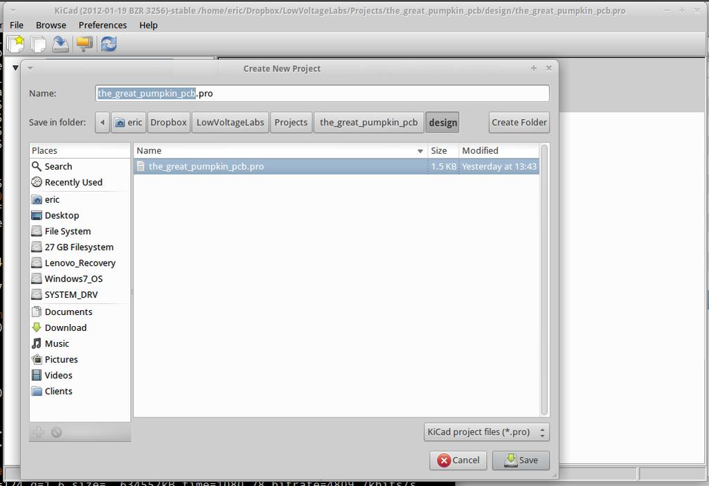
12
13
14

15

16 Add a component with shift-a

17
18
19 Component editor
20
21 Add wires with shift-w

22 Placing power and GND symbols, shift-p
23

24
25 Almost finished with the schematic
26 Annotate the schematic
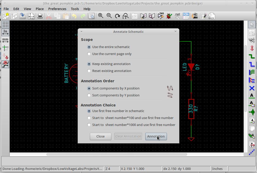
27

28 Finished schematic
29 Create a board with KiCAD What is a PCB? What is a KiCAD? Block diagram Schematic Schematic attribute editor Error check the schematic PCB layout Error check the layout Gerber files Build boards
30 Error rule check the schematic

31
32
33
34 Generate a netlist

35
36 Create a board with KiCAD What is a PCB? What is a KiCAD? Block diagram Schematic Schematic attribute editor - CvPCB Error check the schematic PCB layout Error check the layout Gerber files Build boards

37

38
39 Create a board with KiCAD What is a PCB? What is a KiCAD? Block diagram Schematic Schematic attribute editor Error check the schematic PCB layout Error check the layout Gerber files Build boards

40
41 PCB module editor

42 Netlist
43

44 Create an outline on the PCB_Edges layer
45
46 Grid
47
48 'm' to move parts, ratsnests to help determine locations
49
50 Place a track with shift-x
51
52 Double click to end the track at the battery
53
54

55
56
57
58 Right click on the zone

59


60 Place text on the board

61 Back copper layer

62
63

64

65
66 Create a board with KiCAD What is a PCB? What is a KiCAD? Block diagram Schematic Schematic attribute editor Error check the schematic PCB layout Error check the layout Gerber files Build boards

67
68 Check for unconnected pads

69
70 Create a board with KiCAD What is a PCB? What is a KiCAD? Block diagram Schematic Schematic attribute editor Error check the schematic PCB layout Error check the layout Gerber files Build boards

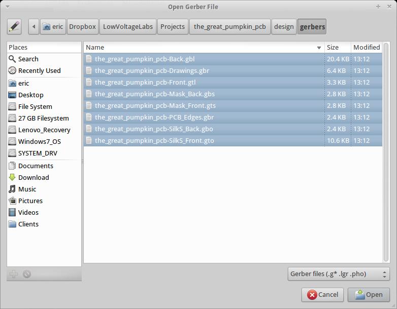
71 File -> Plot to generate gerber files
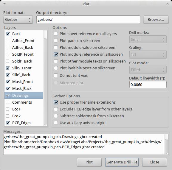
72

73
74
75

76
77
78
79
80
81

82
83 Create a board with KiCAD What is a PCB? What is a KiCAD? Block diagram Schematic Schematic attribute editor Error check the schematic PCB layout Error check the layout Gerber files Build boards
84 PCB price factors: complexity - small space/trace or special features size of the board and number of boards turn around time
85 PCB Pooling Services DorkbotPDX PCB Qty=3, two-layer boards: $5 per square inch Today's board example would be ~$7.50 for qty=3 Qty=3, four-layer boards: $10 per square inch Purple solder mask 2 layer boards ship approx in 14 days Prices include shipping Midnight Maker Qty=3, two-layer boards: $5 per square inch Today's board example would be ~$7.50 for qty=3 Qty=3, four-layer boards: $10 per square inch Black solder mask One week manufacturing time Prices include shipping
86 PCB Service Companies Sunstone Mulino, OR ValueProto service Today's example board would cost $38.50, qty=3 Available in two weeks or less includes shipping Also have more options for faster turn around time Seeed Studio Fusion PCB service $9.90 for 10 boards up to 5cm X 5cm in size Today's example board would cost $9.90, Qty=10 Plus shipping $4.10 to ship to the State of Washington Shipping to the US


87 PCB samples thanks to: DorkbotPDX PCB Midnight Maker Seeed Studio Eric Thompson LowVoltageLabs.com
PCB Fundamentals Quiz
 1. PCBs should be fabricated with layers. a. Odd Number of b. Even Number of c. Any Number of 2. Which of the following is not taken into consideration when calculating the characteristic impedance for
EEC WINTER Instructor: Xiaoguang Leo" Liu. Application Note. Baseband Design. Duyen Tran ID#: Team DMK
 EEC 134 --- WINTER 2016 Instructor: Xiaoguang Leo" Liu Application Note Baseband Design Duyen Tran ID#: 999246920 Team DMK 1 This application note provides the process to design the baseband of the radar
Gerber Setup. Modified by Susan Riege on 4-Aug Parent page: WorkspaceManager Dialogs
 Gerber Setup Modified by Susan Riege on 4-Aug-2015 Parent page: WorkspaceManager Dialogs Other Related Resources Options for Project - Options Tab (Dialog) Generate Output Files (Dialog) Aperture (Dialog)
Getting Started in Eagle Professional Schematic Software. Tyler Borysiak Team 9 Manager
 Getting Started in Eagle 7.3.0 Professional Schematic Software Tyler Borysiak Team 9 Manager 1 Executive Summary PCBs, or Printed Circuit Boards, are all around us. Almost every single piece of electrical
PCB Layout. Date : 22 Dec 05. Prepare by : HK Sim Prepare by : HK Sim
 PCB Layout Date : 22 Dec 05 Main steps from Schematic to PCB Move from schematic to PCB Define PCB size Bring component from schematic to PCB Move the components to the desire position Layout the path
PCB Design (with EAGLE tutorial) TA: Robert Likamwa ELEC 424, Fall 2010
 TA: Robert Likamwa ELEC 424, Fall 2010") PCB Design (with EAGLE tutorial) TA: Robert Likamwa ELEC 424, Fall 2010 Printed Circuit Boards What are they? How can I make one? 424 Project description Eagle Tutorial http://www.electronicmanufacturers.co.za/
PCB Design (with EAGLE tutorial) TA: Robert Likamwa ELEC 424, Fall 2010 Printed Circuit Boards What are they? How can I make one? 424 Project description Eagle Tutorial http://www.electronicmanufacturers.co.za/
PCB Fundamentals Quiz
 1. PCBs should be fabricated with layers. a. Odd Number of b. Even Number of c. Any Number of Reason: Using an odd number of layers may result in board warpage. 2. Which of the following is not taken into
PCB layout tutorial MultiSim/Ultiboard
 PCB layout tutorial MultiSim/Ultiboard The basic steps in designing a PCB Paper design and prototype of the basic circuit. Identify the parts and the footprints that will be used. Make a circuit schematic,
Published on Online Documentation for Altium Products (http://www.altium.com/documentation)
") Published on Online Documentation for Altium Products (http://www.altium.com/documentation) Home > Gerber Setup A New Era for Documentation Modified by Phil Loughhead on Jun 17, 2017 The Gerber Setup dialog
Published on Online Documentation for Altium Products (http://www.altium.com/documentation) Home > Gerber Setup A New Era for Documentation Modified by Phil Loughhead on Jun 17, 2017 The Gerber Setup dialog
EECAD s MUST List. Requests for drawing numbers MUST be submitted via the EECAD job request form at
 Customers are required to follow certain criteria for all designs whether they are ultimately done in EECAD or by the customers themselves. These criteria, approved by EES Management, are listed below:
Introduction to NI Multisim & Ultiboard Software version 14.1
 School of Engineering and Applied Science Electrical and Computer Engineering Department Introduction to NI Multisim & Ultiboard Software version 14.1 Dr. Amir Aslani August 2018 Parts Probes Tools Outline
Project Design for TAPR Manufacturing. Design for Manufacturability
 Project Design for TAPR Manufacturing Design for Manufacturability -or- How to ease your project into mass production with the least amount of pain (both yours and TAPR s) Scotty Cowling, WA2DFI 2010 Dayton
Intro PCBs. Jonathan Bachrach. September 8, EECS UC Berkeley
 Intro PCBs Jonathan Bachrach EECS UC Berkeley September 8, 2016 Last Time Introduced Nucleo-L432KC 1 Today 2 Going to talk about PCBs and Soldering wisegeek Traditional PCB CAD Design 3 schematic capture
Sample VA Technical Documentation Assessments
 Sample 243-251-VA Technical Documentation Assessments EVALUATION OF ASSESSMENT TOOLS USED TO MEASURE ACHIEVEMENT OF IET COURSE COMPETENCIES Please attach copies of all assessment tools used in this section
Allegro New Products - DFM / Rule Checkers
 Allegro New Products - DFM / Rule Checkers Eric / Graser 16 / Oct / 2015 Topic Allegro DFM Checker in Allegro PCB Manufacturing Option Allegro PCB Rules Developer / Checker Option PCB Design & Production
Gerber Setup. Summary. Access. Options/Controls. General Tab. Modified by on 13-Sep Parent page: WorkspaceManager Dialogs
 Gerber Setup Old Content - visit altium.com/documentation Modified by on 13-Sep-2017 Parent page: WorkspaceManager Dialogs Summary Each Gerber file corresponds to one layer in the physical board the component
LED Field Strength Indicator Kit
 LED Field Strength Indicator Kit Description The Field Strength Indicator kit from Qrpkits.com provides a visual way to monitor RF fields through the brightness of an LED. It will respond to RF fields
+Denotes lead(pb)-free and RoHS compliant.
-free and RoHS compliant.") 19-4552; Rev 0; 4/09 MAX9918 Evaluation Kit General Description The MAX9918 evaluation kit (EV kit) provides a proven design to evaluate the MAX9918 wide input range, precision unidirectional/bidirectional,
19-4552; Rev 0; 4/09 MAX9918 Evaluation Kit General Description The MAX9918 evaluation kit (EV kit) provides a proven design to evaluate the MAX9918 wide input range, precision unidirectional/bidirectional,
Creating another Printed Circuit Board
 Appendix C Creating another Printed Circuit Board In this chapter, we will learn the following to World Class standards: Starting with a Finished Schematic Creating the Layers for the Printed Circuit Board
Wheatstone Bridge. M16C Microcontroller Strain Gauge (temperature compensation)
") Overview Eagle Version: 5.11.0 Circuit: Strain gauge amplifier for interface with a microcontroller. Time Requirements 2 + 2 + 2 hours. This three part guide is intended to provide an introduction to PCB
Overview Eagle Version: 5.11.0 Circuit: Strain gauge amplifier for interface with a microcontroller. Time Requirements 2 + 2 + 2 hours. This three part guide is intended to provide an introduction to PCB
Improve SMT Assembly Yields Using Root Cause Analysis in Stencil Design
 Improve SMT Assembly Yields Using Root Cause Analysis in Stencil Design Greg Smith FCT Assembly, Inc. gsmith@fctassembly.com This paper and presentation was first presented at the 2017 IPC Apex Expo Technical
EAGLE: Using the computer for circuit layout
 EAGLE: Using the computer for circuit layout Introduction You ve probably noticed that these lab exercises contain some nice circuit diagrams. They were drawn using a program called EAGLE: Easily Applicable
Quiz Design Question. Signal Grounds. Wires Theory vs Reality
 Quiz Design Question Quiz Thu 2:30p The design question will involve one of Op amp or BJT(s) or MOSFET(s). One or more of these datasheets will be included in the exam: OP AMP http://web.mit.edu/6.101/www/reference/lm741.pdf
Preliminary Datasheet
 Product Description The is a reflective SPDT RF switch that can be used in high power and good performance WLAN 802.11 a/b/g/n/ac/ax, DOCSIS 3.0/3.1 and Wireless Communication applications. This device
Value Stream Map Process Flow
 Value Stream Map Process Flow Pre- Locate Data Value Stream Mapping Has The Following Characteristics: It Is A Comprehensive And Detailed Graphical Document That Lists Every Business Unit, Organization,
Preliminary Datasheet
 Product Description The is a reflective SPDT RF switch that can be used in high power and good performance WLAN 802.11 a/b/g/n/ac/ax, DOCSIS 3.0/3.1 and Wireless Communication applications. This device
Pacific Antenna - Easy TR Switch
 Pacific Antenna - Easy TR Switch Kit Description The Easy TR Switch is an RF sensing switch that can be used to switch an antenna between a receiver and transmitter. It also has a second switched pair
Pacific Antenna Easy TR Switch
 Pacific Antenna Easy TR Switch Kit Description The Easy TR Switch is an RF sensing circuit with a double pole double throw relay that can be used to automatically switch an antenna between a separate receiver
RF System: Baseband Application Note
 Jimmy Hua 997227433 EEC 134A/B RF System: Baseband Application Note Baseband Design and Implementation: The purpose of this app note is to detail the design of the baseband circuit and its PCB implementation
Tutorial In Practical Circuit Board Design Ben LeVesque ECE480 Team 3 November 9 th, 2007
 utorial In Practical Circuit Board Design Ben LeVesque ECE480 eam 3 November 9 th, 2007 Keywords Circuit board, Cadence, Layout, Capture, post processing, trace capacity, trace ampacity, Via Abstract his
QPI-5L. 14 Amp Active EMI Filter for 24 V DC Bus. Features. Description. Applications 查询 QPI-5L 供应商. QuietPower
 查询 5L 供应商 5L QuietPower 14 Amp Active EMI Filter for 24 V DC Bus Description The 5 active EMI filter attenuates conducted common-mode (CM) and differential-mode (DM) noise over the CISPR22 frequency range
CAE-CAD-CAM TECHNIQUES FOR DEVELOPMENT OF ELECTRONIC MODULES
 CAE-CAD-CAM TECHNIQUES FOR DEVELOPMENT OF ELECTRONIC MODULES Ciprian Ionescu Faculty of Electronics and Information Technology University Politehnica of Bucharest Center of Technological Electronics and
IME-100 ECE. Lab 1. Electrical and Computer Engineering Department Kettering University. G. Tewolde, IME100-ECE,
 IME-100 ECE Lab 1 Electrical and Computer Engineering Department Kettering University 1-1 IME-100, ECE Lab1 Circuit Design, Simulation, and Layout In this laboratory exercise, you will do the following:
SGM W Mono Fully Differential Audio Power Amplifier
 .3W Mono Fully Differential GENERAL DESCRIPTION The SGM4995 is a fully differential audio power amplifier that is designed for portable communication device applications and demanding applications in mobile
Voltage Variable Equalizer
 Surface Mount Voltage Variable Equalizer 5Ω 95 to 2 MHz The Big Deal Adjustable attenuation slope Supply voltage from + to + IP3 +55 dbm typical Minimal deviation from linear loss, ±.5dB CASE STYLE: HE1354
SP A Discrete Unidirectional TVS Diode
 SP1212 12A Discrete Unidirectional TVS Diode RoHS Pb GREEN Description The SP1212 unidirectional TVS is fabricated in a proprietary silicon avalanche technology. These diodes provide a high ESD (electrostatic
SGM W Fully Differential Audio Power Amplifier
 .3W Fully Differential GENERAL DESCRIPTION The SGM4895 is a fully differential audio power amplifier that is designed for portable communication device applications and demanding applications in mobile
Fertigungsdaten aufbereiten mit GerbTool und VisualCAM
 FlowCAD Webinar Fertigungsdaten aufbereiten mit GerbTool und VisualCAM Overview Introduction News 16.2 Gerber Format Importing Data Layer Compare DFM Analysis Modifications on existing designs artwork
Wires, Ground loops Thermal considerations Energy PCB Layout Spring 2018 Lecture 12 1
 Wires, Ground loops Thermal considerations Energy PCB Layout 6.101 Spring 2018 Lecture 12 1 4 Quiz Grades 3 2 Quiz Grades 1 0
Code Practice Oscillator (CPO) For kit building instructions turn to Page 3.
 For kit building instructions turn to Page 3.") Code Practice Oscillator (CPO) For kit building instructions turn to Page 3. Overview Many thanks for your purchase of this code practice oscillator or CPO, this guide is intended to allow you to quickly
Code Practice Oscillator (CPO) For kit building instructions turn to Page 3. Overview Many thanks for your purchase of this code practice oscillator or CPO, this guide is intended to allow you to quickly
PCB Artist Quickstart Guide Revision 01
 UT DALLAS Erik Jonsson School of Engineering & Computer Science PCB Artist Quickstart Guide Revision 01 Pete Semig Ph.D. Student-Dr. Jafari Analog Application Engineer-TI 1 Important Terminology PCB Artist
HMC656LP2E TO HMC658LP2E v
 Typical Applications The HMC656LP2E - HMC65LP2E are ideal for: Fiber Optics Microwave Radio Military & Space Test & Measurement Scientifi c Instruments RF / Microwave Circuit Prototyping Features 3 Attenuator
Analog Devices Welcomes Hittite Microwave Corporation NO CONTENT ON THE ATTACHED DOCUMENT HAS CHANGED
 Analog Devices Welcomes Hittite Microwave Corporation NO CONTENT ON THE ATTACHED DOCUMENT HAS CHANGED www.analog.com www.hittite.com THIS PAGE INTENTIONALLY LEFT BLANK Typical Applications The HMC652LP2E
MB1013, MB1023, MB1033, MB1043
 HRLV-MaxSonar - EZ Series HRLV-MaxSonar - EZ Series High Resolution, Low Voltage Ultra Sonic Range Finder MB1003, MB1013, MB1023, MB1033, MB1043 The HRLV-MaxSonar-EZ sensor line is the most cost-effective
Part No ISM or ISM & BT or GPS Stamp Metal Embedded Antenna
 DATASHEET Part No. 1002427 Product: ISM/GPS/BT SMT Stamp Metal Antenna Part No. 1002427 ISM or ISM & BT or GPS Stamp Metal Embedded SMT Antenna 868 MHz, 915 MHz, 1.575 GHz, 2.4 GHz Supports: Wi-Fi applications,
Processing Gerber Files in CircuitPro
 Processing Gerber Files in CircuitPro Requirements 1. Circuit Pro version 1.5 revision 164 or higher 2. Set of Gerber Files Process Steps 1. Execute Process Planning Wizard. a. Press the process planning
2x2 mm LGA Package Guidelines for Printed Circuit Board Design. Figure 1. 2x2 mm LGA package marking information.
 2x2 mm LGA Package Guidelines for Printed Circuit Board Design This technical note is intended to provide information about Kionix s 2 x 2 mm LGA packages and guidelines for developing PCB land pattern
TN008. PCB Design Guidelines for 2x2 LGA Sensors. Introduction. 2x2 LGA Package Marking
 PCB Design Guidelines for 2x2 LGA Sensors Introduction This technical note is intended to provide information about Kionix s 2 x 2 mm LGA packages and guidelines for developing PCB land pattern layouts.
TD-DEV V Technical Specification
 High-Efficiency MODULE Carrier Board TD-DEV-500-12V Technical Specification POWER SUPPLY TECHNOLOGY FEATURES Low profile 1U, 500W power supply High efficiency power supply Fully integrated with CPU control
RF circuit fabrication rules
 RF circuit fabrication rules Content: Single layer (ref. page 4) No vias (ref. page 4) With riveted vias (ref. pages 4,5,6) With plated vias (ref. pages 4, 5,7,8,9,10,11) Component assembly (ref. pages
DC Operating Point, I-V Curve Trace. Author: Nate Turner
 DC Operating Point, I-V Curve Trace Author: Nate Turner Description: This tutorial demonstrates how to print the DC-Operating Point as well as trace the I-V curves for a transistor in the tsmc 180nm process.
CHAPTER 3 PROJECT METHODOLOGY
 CHAPTER 3 PROJECT METHODOLOGY 3.1 Introduction This chapter will cover the details explanation of methodology that is being used to make this project complete and working well. Many methodology or findings
Evaluates: MAX6397. MAX6397 Evaluation Kit. General Description. Quick Start. Features. Ordering Information. Procedure
 General Description The MAX6397 evaluation kit (EV kit) demonstrates a high-voltage overvoltage protection circuit for applications that must survive load dump and high-voltage transient conditions. This
The Engineer s Thumb Compressor/Limiter ValveWizard PCB User Guide (Issue 3 PCBs)
") The Engineer s Thumb Compressor/Limiter ValveWizard PCB User Guide (Issue 3 PCBs) Fig. 1: Circuit schematic Fig. 2: Component layout Fig. 3: Wiring diagram (with millennium bypass) Before populating the
The Engineer s Thumb Compressor/Limiter ValveWizard PCB User Guide (Issue 3 PCBs) Fig. 1: Circuit schematic Fig. 2: Component layout Fig. 3: Wiring diagram (with millennium bypass) Before populating the
One-Wire Lightning Monitor
 One-Wire Lightning Monitor This article describes the construction of an experimental lightning monitor for use with the Dallas Semiconductor 1-wire bus. This monitor provides real-time data on lightning
Ruth Kastner Eli Moshe. Embedded Passives, Go for it!
 Ruth Kastner Eli Moshe Embedded Passives, Go for it! Outline Description of a case study: Problem definition New technology to the rescue: Embedded passive components Benefits from new technology Design
LPKF CircuitCAM 6.1 Stencil The New Software Interface for your LPKF StencilLaser
 Design Rule Check according to: IPC-7525A LPKF CircuitCAM 6.1 Stencil The New Software Interface for your LPKF StencilLaser Higher speeds greater efficiency 50% faster computing time Optimized paths 20%
PCB Production Methods
 PCB Production Methods PCB Development Process Summary Manufacturing Constraints Gerber Schematic Board Manufacture This is art! Ensure that the schematic is accurate. Run the ERC often. This is art! Ensure
Sherlock Solder Models
 Introduction: Sherlock Solder Models Solder fatigue calculations in Sherlock are accomplished using one of the many solder models available. The different solder models address the type of package that
Using EAGLE: Board Layout a
 Using EAGLE: Board Layout a learn.sparkfun.com tutorial Available online at: http://sfe.io/t111 Contents Previously on Using EAGLE Layers Overview Arranging the Board Routing the Board Checking for Errors
5-Channel LiPo-Cell Electronic Load Tester Kit (LELTx5) PART NO
 PART NO") 5-Channel LiPo-Cell Electronic Load Tester Kit (LELTx5) PART NO. 2259489 Configured as five independent (up to) 100.0mA constant current loads (each), the LELTx5 is a versatile and valuable piece of test
5-Channel LiPo-Cell Electronic Load Tester Kit (LELTx5) PART NO. 2259489 Configured as five independent (up to) 100.0mA constant current loads (each), the LELTx5 is a versatile and valuable piece of test
E-ORIGAMI MATERIALS. There are three steps to this project
 There are three steps to this project I. Learning to fold the origami balloon II. Building the circuit III. Folding the circuit into an e-origami balloon. I. Learning to fold the origami balloon. E-ORIGAMI
User2User The 2007 Mentor Graphics International User Conference
 7/2/2007 1 Designing High Speed Printed Circuit Boards Using DxDesigner and Expedition Robert Navarro Jet Propulsion Laboratory, California Institute of Technology. User2User The 2007 Mentor Graphics International
MIC4812. Features. General Description. Applications. Typical Application
 High Current 6 Channel Linear WLED Driver with DAM and Ultra Fast PWM Control General Description The is a high efficiency linear White LED (WLED) driver designed to drive up to six high current WLEDs
MADS T. Schottky Limiter DC - 6 GHz. Features. Functional Schematic. Description. Pin Configuration 3. Ordering Information 1,2.
 Features 3 Terminal LPF Broadband Shunt Structure Low Slope Resistance, 7 Ω +3 dbm Peak and CW Power Handling.6 db Shunt Insertion Loss +2 dbm Flat Leakage Power Lead-Free 1. x 1.2 mm 6-lead TDFN Package
Subject Description Form. Industrial Centre Training I for EIE. Upon completion of the subject, students will be able to:
 Subject Description Form Subject Code Subject Title Credit Value IC2114 Industrial Centre Training I for EIE 5 training credits Level 2 Pre-requisite/ Co-requisite/ Exclusion Objectives Intended Subject
DEVELOPMENT OF ANDRO HUMANOID ROBOT ARM
 International Journal of Mechanical Engineering and Technology (IJMET) Volume 8, Issue 7, July 2017, pp. 537 549, Article ID: IJMET_08_07_061 Available online at http://www.ia aeme.com/ijmet/issues.asp?jtype=ijmet&vtyp
Low Power GaAs MMIC Double Balanced Mixer. Refer to our website for a list of definitions for terminology presented in this table.
 Low Power GaAs MMIC Double Balanced Mixer MM1-0212LSM 1. Device Overview 1.1 General Description The MM1-0212LSM is a low power GaAs MMIC double balanced mixer that operates at LO powers as a low as +1
BSW MHz-6000MHz High Linearity Reflective SPDT RF switch. Product Description. Package Type. Device Features - Common.
 Product Description The BSW6321 is a reflective SPDT RF switch that can be used in high power and good performance WiMAX 802.16, WLAN 802.11 a/b/g/n/ac/ax and DOCSIS 3.0/3.1 applications. This device is
Improve SMT Assembly Yields Using Root Cause Analysis in Stencil Design
 Improve SMT Assembly Yields Using Root Cause Analysis in Stencil Design Greg Smith FCT Assembly, Inc. gsmith@fctassembly.com This paper and presentation was first presented at the 2017 IPC Apex Expo Technical
The UM4684 is a sub 1Ω (0.5Ω at 2.7V) dual SPDT analog switch designed for low voltage
 dual SPDT analog switch designed for low voltage") General Description 0.5Ω Low-Voltage Dual SPDT Analog Switch H CSP10 2.0 1.5 EEUE MSOP10 The is a sub 1Ω (0.5Ω at 2.7V) dual SPDT analog switch designed for low voltage applications. The has on-resistance
General Description 0.5Ω Low-Voltage Dual SPDT Analog Switch H CSP10 2.0 1.5 EEUE MSOP10 The is a sub 1Ω (0.5Ω at 2.7V) dual SPDT analog switch designed for low voltage applications. The has on-resistance
Part No. M Ceramic Wi-Fi / Bluetooth Antenna
 DATASHEET Part No. M830320 Product: Wi-Fi/Bluetooth Ceramic Antennas Part No. M830320 Wi-Fi / BT / Zigbee Ceramic Antennas 2.4 GHz Supports: Wi-Fi applications, Agriculture, Automotive, Bluetooth, Zigbee,
Pin Connections and Package Marking. GUx
 Surface Mount RF PIN Switch Diodes Technical Data HSMP-389x Series HSMP-89x Series Features Unique Configurations in Surface Mount Packages Add Flexibility Save Board Space Reduce Cost Switching Low Capacitance
GaAs MMIC devices are susceptible to Electrostatic Discharge. Use proper ESD precautions when handling these items.
 The is a broadband, power efficient GaAs PHEMT distributed amplifier in a 4mm QFN surface mount package. The is designed to provide optimal LO drive for T3 mixers. Typically, ADM-26-2931SM provides. db
Embedded systems. Exercise session 2. Important Circuit Components Circuit Design
 Embedded systems Exercise session 2 Important Circuit Components Circuit Design Communications Contact Mail : michael.fonder@ulg.ac.be Website for the exercise sessions and the project : http://www.montefiore.ulg.ac.be/~mfonder/info0064/
Pacific Antenna Field Strength Indicator Kit
 Pacific Antenna Field Strength Indicator Kit Description The Field Strength Indicator kit from Pacific Antenna provides a visual way to monitor the presence and relative strength RF fields through the
WEBS-MT/R Tower Installation Instructions
 I. Introduction This manual is for tower installation only. For instructions on installing the anchor bolts into the foundation, see the ETP-MT/R Anchor Bolt Installation Instructions. II. Contents Before
LM384-5-W Audio Power Amplifier
 LM384-5-W Audio Power Amplifier Features Typical Application Wide supply voltage range: 12V to 26V click for larger image Low quiescent power drain Voltage gain fixed at 50 High peak current capability:
Features. = +25 C, 50 Ohm System, Vcc= 5V
 v1.71 HMC6S8G DIVIDE-BY-8, DC - 12. GHz Typical Applications Prescaler for DC to X Band PLL Applications: Satellite Communication Systems Fiber Optic Pt-Pt and Pt-MPt Radios VSAT Functional Diagram Features
Via Stitching. Contents
 Via Stitching Contents Adding Stitching Vias to a Net Stitching Parameters Clearance from Same-net Objects and Edges Clearance from Other-net Objects Notes Via Style Related Videos Stitching Vias Via
HMC1013LP4E. SDLVAs - SMT. SUCCESSIVE DETECTION LOG VIDEO AMPLIFIER (SDLVA), GHz
, GHz") v.9 HMCLPE AMPLIFIER (SDLVA),.5-8.5 GHz Typical Applications The HMCLPE is ideal for: EW, ELINT & IFM Receivers DF Radar Systems ECM Systems Broadband Test & Measurement Power Measurement & Control Circuits
v.9 HMCLPE AMPLIFIER (SDLVA),.5-8.5 GHz Typical Applications The HMCLPE is ideal for: EW, ELINT & IFM Receivers DF Radar Systems ECM Systems Broadband Test & Measurement Power Measurement & Control Circuits
Own Your Technology Presents Workshop on
 Own Your Technology Presents Workshop on PCB Designing ------------OUR FORTE------------ AERO MODELLING INTERNET OF THINGS EMBEDDED SYSTEMS ROBOTICS MATLAB & MACHINE VISION VLSI & VHDL ANDRIOD APP DEVELOPMENT
WPM2005 Power MOSFET and Schottky Diode
 WPM5 Power MOSFET and Schottky Diode Features Featuring a MOSFET and Schottky Diode Independent Pinout to each Device to Ease Circuit Design Ultra Low V F Schottky Applications Li--Ion Battery Charging
Evaluation Board for Filterless Class-D Audio Amplifier EVAL-SSM2304
 Evaluation Board for Filterless Class-D Audio Amplifier EVAL-SSM04 FEATURES Highly configurable DIP switch settings: input configuration, coupling methods, and shutdown control Optional dc power supply
TQQ7399 DC 2700 MHz Through Line
 Applications General Purpose Wireless RF Bypass Paths Microwave Radio Test & Measurement Scientific Instruments Product Features 6 Pin 3 x 3 mm leadless SMT Package Functional Block Diagram DC 2700 MHz
HMC722LP3E HIGH SPEED LOGIC - SMT. 13 Gbps, FAST RISE TIME AND/NAND/OR/NOR GATE, w/ PROGRAMMABLE OUTPUT VOLTAGE. Typical Applications.
 Typical Applications Features The HMC722LPE is ideal for: RF ATE Applications Broadband Test & Measurement Serial Data Transmission up to 1 Gbps Digital Logic Systems up to 1 GHz NRZ-to-RZ Conversion Functional
Owned by Dipl. Ing. Mario Blunk Buchfinkenweg Erfurt / Germany
 Owned by Dipl. Ing. Mario Blunk Buchfinkenweg 3 99097 Erfurt / Germany Phone +49 (0)361 6022 5184 Email info@blunk-electronic.de Internet www.blunk-electronic.de Doc. Vers. 2017-08-10 Design Reviews Surveys
GaAs MMIC devices are susceptible to Electrostatic Discharge. Use proper ESD precautions when handling these items.
 ADM-26-929SM The ADM-26-929SM is a broadband, efficient GaAs PHEMT distributed amplifier in a 4mm QFN surface mount package. It is designed to provide optimal LO drive for T3 mixers and offers 13 db typical
MAX9633 Evaluation Kit Evaluates: MAX9633
 General Description The MAX9633 evaluation kit (EV kit) provides a proven design to evaluate the MAX9633 dual, low-noise, lowdistortion op amp that is optimized to drive ADCs for use in applications from
WEBS-MT/R Tower Installation Instructions
 I. Introduction This manual is for tower installation only. For instructions on installing the anchor bolts into the foundation, see the ETP-MT/R Anchor Bolt Installation Instructions. II. Contents Before
Embedded systems. Exercise session 3. Important Circuit Components Circuit Design
 Embedded systems Exercise session 3 Important Circuit Components Circuit Design Deadline 1 reminder Objective Concise but complete reminder of your project objectives. Hardware Clear and complete schematic
S CLK Pad for External Clock Frequency S Lead(Pb)-Free and RoHS Compliant S Proven PCB Layout
-Free and RoHS Compliant S Proven PCB Layout") General Description The MAXFILTERBRD is an unpopulated PCB design to evaluate the MAX7408 MAX7415/ 5th-order, lowpass, switched-capacitor filters (SCFs). Contact the factory for free samples of the pin-compatible
General Description The MAXFILTERBRD is an unpopulated PCB design to evaluate the MAX7408 MAX7415/ 5th-order, lowpass, switched-capacitor filters (SCFs). Contact the factory for free samples of the pin-compatible
ECE 4370: Antenna Design Fall 2012 Design Project: 5.8 GHz High-Directivity Antenna Ryan Bahr, David Giles, Brian Palmer, Dan Russo
 ECE 4370: Antenna Design Fall 2012 Design Project: 5.8 GHz High-Directivity Antenna Ryan Bahr, David Giles, Brian Palmer, Dan Russo Specifications: The antenna was required to operate with linear polarization
FEATURES OUT OE GND ISET VDD OUT OE GND ISET VDD TO-220-5L. (Top View)
") GENERAL DESCRIPTION The LSP7706 is a high voltage, low dropout current regulator for high power LED lighting. The LSP can handle the maximum output current up to 1.1Amp. The output current can also be
GENERAL DESCRIPTION The LSP7706 is a high voltage, low dropout current regulator for high power LED lighting. The LSP can handle the maximum output current up to 1.1Amp. The output current can also be
--- An integrated 3D EM design flow for EM/Circuit Co-Design
 ADS users group meeting 2009 Rome 13/05, Böblingen 14-15/05, Massy 16/06 --- An integrated 3D EM design flow for EM/Circuit Co-Design Motivations and drivers for co-design Throw-The-Die-Over-The-Wall,
Precision Range Sensing Free run operation uses a 2Hz filter, with. Stable and reliable range readings and
 HRLV-MaxSonar - EZ Series HRLV-MaxSonar - EZ Series High Resolution, Precision, Low Voltage Ultrasonic Range Finder MB1003, MB1013, MB1023, MB1033, MB10436 The HRLV-MaxSonar-EZ sensor line is the most
ICS511 LOCO PLL CLOCK MULTIPLIER. Description. Features. Block Diagram DATASHEET
 DATASHEET ICS511 Description The ICS511 LOCO TM is the most cost effective way to generate a high quality, high frequency clock output from a lower frequency crystal or clock input. The name LOCO stands
DC to 1000 MHz IF Gain Block ADL5530
 Data Sheet FEATURES Fixed gain of 16. db Operation up to MHz 37 dbm Output Third-Order Intercept (OIP3) 3 db noise figure Input/output internally matched to Ω Stable temperature and power supply 3 V or
Improve SMT Assembly Yields Using Root Cause Analysis in Stencil Design
 Improve SMT Assembly Yields Using Root Cause Analysis in Stencil Design Greg Smith FCT Assembly, Inc. Greeley, CO Abstract Reduction of first pass defects in the SMT assembly process minimizes cost, assembly
MC-1010 Hardware Design Guide
 MC-1010 Hardware Design Guide Version 1.0 Date: 2013/12/31 1 General Rules for Design-in In order to obtain good GPS performances, there are some rules which require attentions for using MC-1010 GPS module.