Millimeter-Wave and Terahertz Systems-on-Chip for Radio, Radar and Imaging Applications
|
|
|
- Joseph Lester
- 5 years ago
- Views:
Transcription
1 Millimeter-Wave and Terahertz Systems-on-Chip for Radio, Radar and Imaging Applications RFIC Mini-Symposium, Tela Aviv University, July Prof. M.-C. Frank Chang University of California, Los Angeles mfchang@ee.ucla.edu 1
2 Outline Mm-Wave and Terahertz Systems-on-Chip Ultra-high-speed (>10Gbps) Near-Field-Communication (NFC) Systems Broadband (57-64GHz) Self-Healing Radio-on-a-chip Mm-Wave to Terahertz ( GHz) Radar and Imaging Common Needs in Digital Controlled Artificial Dielectric (DiCAD) with Reconfigurable/Tunable Permittivity Historical Artificial Dielectric Synthesizing DiCAD in Deep-Scaled CMOS Reconfigurable/Scalable DiCAD Circuit Designs Linear phase shift and Impedance Matching Direct frequency modulation/de-modulation Broadband frequency synthesis High PAE power amplifier
3 Near Field Communication Systems
4 Near Field Coupled WaveConnector Near-field-Communication at multi-giga-bit/sec Ultra-high data rate (>10gbps) for short distance and secured communications Protocol-transparent, near-universal applications Ends the electrical and mechanical compromises


5 WaveConnector in Action Link demonstration Tiny, <1mm 2 chips Smaller than the chip caps! Mounted along PCB edges 60 GHz carrier, ASK modulated Error-free operation over 10Gb/s up to a few centimeters Click image to play video 1.2mm RX chip TX chip 1.2mm Closeup showing chips mounted face-up and wire-bonded to PCB 0.6mm 0.6mm
6 60GHz Self-Healing Radio-on-a-chip for IEEE ad and WIGIG
 for IEEE 15.")

7 60GHz Radio-on-a-Chip (RoC) UCLA students designing Self-Healing Reconfigurable 4Gigabit/sec Radio-on-a-Chip (RoC) for IEEE 15.3c, WIGIG, WLAN 11ad system applications. The 65nm CMOS RoC contains 57-65GHz Transmitter, Receiver, Frequency Synthesizer, ADC/DAC, Digital Baseband.. About 25million Transistors


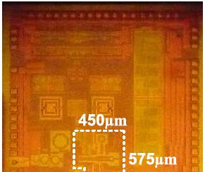
8 57-64GHz Radio-on-a-Chip Feature Size Value 4.0 x 4.0 mm Pads 145 On-Chip Cap 285 pf Power Domains 44 RF Control 255 RF Frequency BB Clock GHz 2.0 GHz In Color!
9 60GHz Radio-on-a-Chip System Performance Metrics/Yield * Based on Test Results from Ten Assembled Die-on-Boards Metric Unit Phase I GNG Performer Status to Date Achieved Baseline Yield Post-Healing Yield Performer Defined Metrics Receiver (X) NF db <6 4.6(Healed)* 0%* 100%* Output Bandwidth GHz 1.2 >1.22- BL-OK* 100%* 100%* Rx OIM3 dbc -40 <-41.3 BL-OK* 100%* 100%* Transmitter P1dB dbm 10 >12.5 BL-OK* 100%* 100%* TX OIM3 dbc (Healed)* 0%* 100%* Synthesizer Phase Noise dbc -90@ 1MHz -94@1MHz BL-OK* 100%* 100%* Channel Frequency GHz n 2.16 N=0 3 Hit all tones with sufficient VCO margin* 100%* 100%* I/Q mismatch dbc (Healed)* 0%* 100%* ADC ENOB Bit > 5.5 >5.8 BL-OK* 100%* 100%* Program GNG Metrics Performance Yield (1 % * 0%* 100* Power Consumption Overhead % %* 785mW* mW* BL-OK*: Baseline Circuit Performance Met Specs Without Healing
10 60GHz 4Gbps Self-Healing Radio Biasing Self-Healing RF Control Clocking Baseline

11 Before and After: Image Healing Carrier Carrier Carrier Image Image Image -40 dbc Initial State Phase Healing Phase + Amplitude + DC


12 TX LO and Image (IQ) Healing System Key Components Knobs: the phase offset, relative gains and DC offset between TX I&Q channel are controlled by the IQ unit. 2. The DAC controller provides test tones for 1 tone and two tone testing. 3. The envelope sensor at the TX output captures the tone information from the 60GHz output spectrum. 4. The parameter estimator evaluates and returns the relative amplitudes of LO leakage, and Image tone power.
13 Code Sweep of Phase Correction vs. Image Phase Sweep Result of code sweep clearly shows that there is a single local minimum corresponding to true zero phase offset between I and Q. IQ Phase offset of transmitter seems to be about 7-10 degrees. Image level is still not in spec because the amplitude mismatch still exists. This must also be healed.
14 Code Sweep of Amplitude Correction vs. Image Amplitude Sweep Once the phase is correctly set the amplitude must also be adjusted to obtain zero mismatch between I and Q. The I channel is held at 255 amplitude so there is about a 10 LSB amplitude mismatch. The image level is can now reach specification.
15 Code Sweep of DC Offset Control vs. LO Leak DC Offset Sweep Result of code sweep clearly shows that there is a single local minimum corresponding to zero DC offset between I and Q. Baseline already meets GNG requirements without applying a correction offset.

16 Linear Extrapolation with Cautious Control Image and LO Healing Algorithm We expect the mismatch will be less than 20 degrees for IQ angle, less than 50 LSBs for amplitude mismatch and less than 50 LSBs for LO leakage from DC and so we do linear extrapolation to first estimate the correct phase setting. After the linear estimation we can do a local 4% of range sweep around the estimated value with a basic search in a small solution space. First heal phase, then amplitude, then DC offset

17 100% Yield from Image Tone Healing
18 100% Yield from TX OIM3 Healing

19 100% Yield from Noise Figure Healing
20 Mm-Wave to Terahertz ( GHz) Imaging and Radar Systems


 Computer floppy disk C)")
21 183GHz CMOS Active Imager Electrical Measurements Imaging Results Measurement Value Frequency 183 GHz NF 9.9 db Power 13.5mW Sensitivity -72 dbm Area um 2 NEP 1.5fw/Hz 0.5 Gain 1.3ms/W Frequency Response Time-Encoded Output Sample-Targets (metals and non-metals) A) Metallic Wrench B) Computer floppy disk C) Football D) Roll of tape *All items were concealed in cardboard boxes


22 Digital Regeneration Receiver Injecting fundamental power into an oscillator shortens the start-up time Adding a digital latch circuit allows the oscillator to restart each clock. When the oscillator starts it triggers the digital reset creating a pulse width proportional to input power


23 DRR Prototype Test Results
 IRR")

 First")


")


24 Tri-Color (350/200/50GHz) IRR Imager (Inter-modulated Regenerative Receiver) First reported architecture for RX to operate above F max Fastest reported silicon receiver (SiGe or CMOS) First multi-band sub-millimeter-wave receiver (3 bands) Chopper Sync RX 350 GHz Chopper Response CMOS Tri-band Receiver 24


25 495 GHz CMOS Super-Regenerative Receiver 495 GHz Regenerative Receiver based on 40nm TSMC CMOS technology with total power consumption of 5mW under 1V supply voltage 495 GHz Chopper Signal 495GHz Image Capture Terahertz System Demonstrations 1. Sensitivity measurement of antenna-less 245 GHz GHz antenna-less imager 3. Imaging Radar Demo


26 Reflective Mode Active Imaging Target is placed at a stand-off distance from imaging system containing source and detector and reflection is measured. The system must accommodate 2X the free space path loss of a regular radio link.
27 Low Physical Reflection Diversity 350 GHz 28 dbm Bottle Acrylic Backdrop Metal Stand Metal Rail The above is illuminated with 28 dbm from a 350 GHz TWT source and detected with a 25fw/Hz 0.5 receiver. Even with high power and low NEP the system is ineffective because the reflection diversity is too low (metal, plastic & fluid all have similar reflection coefficients).


![[1] Ken Cooper et.al.](/docs-images/82/86575638/images/28-4.jpg "(NASA Jet Propulsion Lab) \"")

28 Incidence Angle is Critical 0º Incidence 350 GHz 2º Incidence 350 GHz Rotating the target even off-axis eliminates the useful information in the image capture because the energy is not reflected back to the receiver [1]. [1] Ken Cooper et.al. (NASA Jet Propulsion Lab) " Penetrating 3D Imaging at 4 and 25m Range Using a Sub-millimeter-Wave Radar IEEE MTT 2008 V56 #12.


29 144 GHz CMOS Sub-Ranging 3D Imaging Radar with <0.7cm Depth Resolution First mm-wave 3D imaging radar in silicon! Quasi-Optical Setup for 144 GHz Radar Presented at ISSCC 2012


30 144 GHz CMOS Sub-Carrier SAR 3D Imaging Radar Results Presented at ISSCC
31 Required mm-wave Device/Circuit Innovations Topology (circuit Architecture) to secure sufficient signal headroom Inter-stage circuitry to optimize I/O impedance and enhance signal gain High permittivity artificial dielectric to shrink dimensions of passives and reduce transmission / resonator / substrate loss over conductive Si substrate Embedded sensors/actuators/controller for selfdiagnosis/healing to optimize system performance yield and counter system performance aging


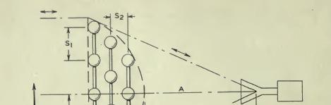
32 Historical Artificial Dielectric W.E. Kock, Metallic delay lenses, Bell Syst. Tech. J, vol. 27, pp , 1948
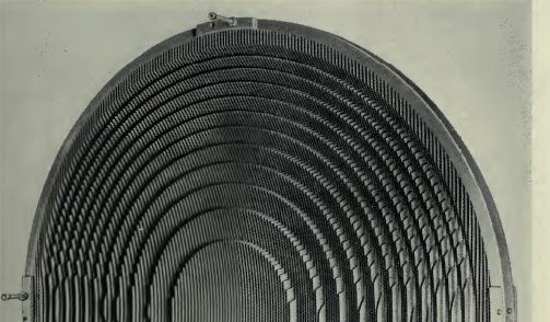

33 Historical Artificial Dielectric (II)
34 Induced Dipole Moment Boosts Permittivity in Capacitor b φ = E 2 Q+q b E 2 b E p -q q φ = b E 2 -Q-q b E 2 Unloaded cell Capacitance C 0 = Q Eb Permittivity boost-factor Loaded cell Capacitance κ = C 0 C 0 Q + q C 0 = Eb
35 Artificial Dielectric Array of identical conducting obstacles embedded in a dielectric medium Displaced charges on obstacles induce dipole field Permittivity boost-factor reduces resonant wavelength and resonator size E ε r Unit cell p x D z a P = Np = b p abc c y = ε E + P = κε E λmedium λad = κ


36 CMOS Artificial Dielectric l=λ/4 w s Transmission line guiding quasi-tem wave 0 C 0 = C Cross-section view of E field vector E κ 5 p 0 t d d(µm)
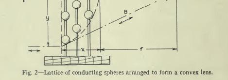
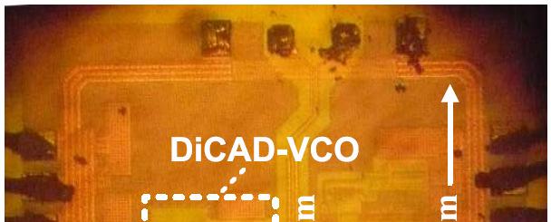
37 Challenges in CMOS MM-Wave VCO High device flicker noise Large WL devices? p-mos? Low-Q lumped passives Skin effect Substrate loss Potential solutions Use distributed coplanar strip line resonator Enhance resonator s Q with on-chip artificial dielectric Outpu noise (A/ Hz) L Device Noises (IBM, 2003) n-mos p-mos SiGe HBTs ktfr ω P 0 ωm AlGaAs/GaAs HBT Frequency (Hz) Leeson s equation 0 ( ω ) = m Q


38 VCO Die/Performance Resonator with embedded artificial dielectrics 100 0µm -94 Offset Varactor area 150µm MHz Offset
39 Performance Comparison Reference Process f 0 (GHz) V DD (V) P DC (mw) PN@1MHz (dbc/hz) FOM Die area (mm 2 ) This work 90nm CMOS J.Kim 1 MTT- S,2003 B.A. Floyd 2 RFIC,2004 InGaP/ GaAs HBT SiGe HBT Y.Cho 3 RFIC,2005 R.Liu 4 ISSCC,2004 P.Huang 5 ISSCC, µm CMOS 0.25µm CMOS 0.13µm CMOS
40 Digitally Controlled Artificial Dielectric (DiCAD) Switch network inserted midway along virtual ground of the artificial dielectric strip (NMOS, π-configuration) Result: Digital control of effective dielectric constant!
 (e) (a) Two sections of 41.")


; (b) for impedance match; (c) for")
41 DiCAD as Analog Control Knob (a ) (b ) (c) (d) (e) (a) Two sections of 41.25um long DiCAD with 15 control switches each, under a differential TML with width of 22um and gap of 50um. The DiCAD bars are 5um wide with a pitch of 5.5um (space=0.5um); (b) for impedance match; (c) for impedance transformation; (d) for frequency selection; (e) for phase shift.
42 48GHz PLL Topology Type-II 3 rd order Integer-N PLL Programmable divide chain (512 to 992, in steps of 32) DiCAD-based mm-wave blocks
43 mm-wave Resonator Design Challenges Goal Minimise and Accurately for Parasitic Capacitance
44 DiCAD-Based Resonators DiCAD developed as a permittivityprogrammable transmission line Fundamental Trade-off Key Benefits: Easily modelled, characterised and simulated Reduces parasitic concerns Enables first-time right mm-wave design Enables fine digital frequency tuning CRatio
45 Additional Resonator Design Choice DiCAD employed in all mm-wave Blocks Ensures frequency alignment Resistor Array used as current source Reduces flicker noise
")


46 VCO Measurement Results (1) DiCAD controlled using 5-bit (32-state) thermometer code KVCO reduced below 1GHz/V across entire band 6 frequencies can be synthesized using 54MHz XO 43.2GHz, GHz, GHz, GHz, GHz and 51.84GHz
47 VCO Measurement Results (2) Distributed nature of DiCAD and use of thermometer codes results in a very linear digital tuning Varactor-size can be minimised

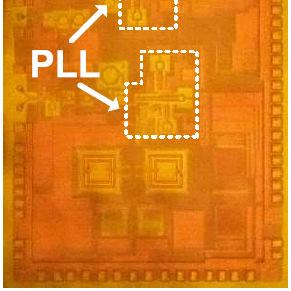
48 Die Micrograph (a) PLL Testchip (b) TRX Testchip
49 Comparison with State-of-the-Art [1] O. Richard et al., ISSCC 2010, pp , Feb. 2010
 vs. freq.")
50 DiCAD for Linear Phase Shifter Linear phase change from o to o Linear increase in ε eff from 18.8 to 32 at 61GHz 35% of physically available range switch resistance and capacitance limit performance Phase (S21) vs. freq. Phase, ε r,eff vs. digital state
51 Direct Frequency Vector Sum Modulator Take advantage of direct frequency architecture, and linear DiCAD Create and add two vectors in opposite quadrants to create sum vector that spans entire I-Q plane Quadrant Phase and Amplitude Shifters (QPAS) only need to work in a single quadrant.


52 DiCAD QPAS Design a dynamically matched amplifier with shunt/open DiCAD stubs and series L networks (similar to Hi-Lo P.S.) Control phase with DiCAD and amplitude with NMOS Switch Sequence State 1: State 2: State 3: State n:

53 Measured Modulation States Measured QPAS shows coverage (S21) of entire quadrant QPAS is well-controlled, and evenly distributed Measured total modulation points at 62.64GHz
54 DiCAD for Digital Constellations Measured (+) and ideal (o) constellation points. Static EVM < -31dB BPSK π/2 QPSK π/2 Star-8QAM π/2 16QAM
55 Summary Scalable SoC Designs based on Digital Controlled Artificial Dielectric (DiCAD) Synthesizing DiCAD in Deep-Scaled CMOS Reconfigurable/Scalable DiCAD Circuit Designs Linear phase shift and Impedance Matching Direct frequency modulation/de-modulation Broadband frequency synthesis High PAE power amplifier Extensive System Applications in mm-wave to Terahertz Spectra Ultra-high-speed (>10Gbps) Near-Field-Communication (NFC) Systems Broadband (57-64GHz) Self-Healing Radio-on-a-chip Mm-Wave to Terahertz ( GHz)Radar and Imaging
ISSCC 2006 / SESSION 17 / RFID AND RF DIRECTIONS / 17.4
 17.4 A 6GHz CMOS VCO Using On-Chip Resonator with Embedded Artificial Dielectric for Size, Loss and Noise Reduction Daquan Huang, William Hant, Ning-Yi Wang, Tai W. Ku, Qun Gu, Raymond Wong, Mau-Chung
Next Generation Communication, Radar, Imaging Systems-on-Chip
 Next Generation Communication, Radar, Imaging Systems-on-Chip (RTSP 2017, Poly Technical University of Bucharest) July 10, 2014 Prof. M.-C. Frank Chang National Chiao Tung University, Hsinchu, Taiwan Email:
Radio Research Directions. Behzad Razavi Communication Circuits Laboratory Electrical Engineering Department University of California, Los Angeles
 Radio Research Directions Behzad Razavi Communication Circuits Laboratory Electrical Engineering Department University of California, Los Angeles Outline Introduction Millimeter-Wave Transceivers - Applications
A 2.6GHz/5.2GHz CMOS Voltage-Controlled Oscillator*
 WP 23.6 A 2.6GHz/5.2GHz CMOS Voltage-Controlled Oscillator* Christopher Lam, Behzad Razavi University of California, Los Angeles, CA New wireless local area network (WLAN) standards have recently emerged
SiNANO-NEREID Workshop:
 SiNANO-NEREID Workshop: Towards a new NanoElectronics Roadmap for Europe Leuven, September 11 th, 2017 WP3/Task 3.2 Connectivity RF and mmw Design Outline Connectivity, what connectivity? High data rates
A 1.7-to-2.2GHz Full-Duplex Transceiver System with >50dB Self-Interference Cancellation over 42MHz Bandwidth
 A 1.7-to-2.2GHz Full-Duplex Transceiver System with >50dB Self-Interference Cancellation Tong Zhang, Ali Najafi, Chenxin Su, Jacques C. Rudell University of Washington, Seattle Feb. 8, 2017 International
A 1.9GHz Single-Chip CMOS PHS Cellphone
 A 1.9GHz Single-Chip CMOS PHS Cellphone IEEE JSSC, Vol. 41, No.12, December 2006 William Si, Srenik Mehta, Hirad Samavati, Manolis Terrovitis, Michael Mack, Keith Onodera, Steve Jen, Susan Luschas, Justin
mm-wave Transceiver Challenges for the 5G and 60GHz Standards Prof. Emanuel Cohen Technion
 mm-wave Transceiver Challenges for the 5G and 60GHz Standards Prof. Emanuel Cohen Technion November 11, 11, 2015 2015 1 mm-wave advantage Why is mm-wave interesting now? Available Spectrum 7 GHz of virtually
ISSCC 2006 / SESSION 20 / WLAN/WPAN / 20.5
 20.5 An Ultra-Low Power 2.4GHz RF Transceiver for Wireless Sensor Networks in 0.13µm CMOS with 400mV Supply and an Integrated Passive RX Front-End Ben W. Cook, Axel D. Berny, Alyosha Molnar, Steven Lanzisera,
ISSCC 2006 / SESSION 33 / MOBILE TV / 33.4
 33.4 A Dual-Channel Direct-Conversion CMOS Receiver for Mobile Multimedia Broadcasting Vincenzo Peluso, Yang Xu, Peter Gazzerro, Yiwu Tang, Li Liu, Zhenbiao Li, Wei Xiong, Charles Persico Qualcomm, San
Technology Trend of Ultra-High Data Rate Wireless CMOS Transceivers
 2017.07.03 Technology Trend of Ultra-High Data Rate Wireless CMOS Transceivers Akira Matsuzawa and Kenichi Okada Tokyo Institute of Technology Contents 1 Demand for high speed data transfer Developed high
26.8: A 1.9GHz Single-Chip CMOS PHS Cellphone
 26.8: A 1.9GHz Single-Chip CMOS PHS Cellphone William W. Si, Srenik Mehta, Hirad Samavati, Manolis Terrovitis, Michael Mack, KeithOnodera, SteveJen, Susan Luschas, Justin Hwang, SuniMendis, DavidSu, BruceWooley
ISSCC 2006 / SESSION 11 / RF BUILDING BLOCKS AND PLLS / 11.9
 ISSCC 2006 / SESSION 11 / RF BUILDING BLOCKS AND PLLS / 11.9 11.9 A Single-Chip Linear CMOS Power Amplifier for 2.4 GHz WLAN Jongchan Kang 1, Ali Hajimiri 2, Bumman Kim 1 1 Pohang University of Science
A 60-GHz Digitally-Controlled Phase Modulator with Phase Error Calibration
 IEICE Society Conference A 60-GHz Digitally-Controlled Phase Modulator with Phase Error Calibration Rui WU, Ning Li, Kenichi Okada, and Akira Tokyo Institute of Technology Background 1 9-GHz unlicensed
ISSCC 2003 / SESSION 20 / WIRELESS LOCAL AREA NETWORKING / PAPER 20.2
 ISSCC 2003 / SESSION 20 / WIRELESS LOCAL AREA NETWORKING / PAPER 20.2 20.2 A Digitally Calibrated 5.15-5.825GHz Transceiver for 802.11a Wireless LANs in 0.18µm CMOS I. Bouras 1, S. Bouras 1, T. Georgantas
95GHz Receiver with Fundamental Frequency VCO and Static Frequency Divider in 65nm Digital CMOS
 95GHz Receiver with Fundamental Frequency VCO and Static Frequency Divider in 65nm Digital CMOS Ekaterina Laskin, Mehdi Khanpour, Ricardo Aroca, Keith W. Tang, Patrice Garcia 1, Sorin P. Voinigescu University
A 2.4-GHz 24-dBm SOI CMOS Power Amplifier with Fully Integrated Output Balun and Switched Capacitors for Load Line Adaptation
 A 2.4-GHz 24-dBm SOI CMOS Power Amplifier with Fully Integrated Output Balun and Switched Capacitors for Load Line Adaptation Francesco Carrara 1, Calogero D. Presti 2,1, Fausto Pappalardo 1, and Giuseppe
Insights Into Circuits for Frequency Synthesis at mm-waves Andrea Mazzanti Università di Pavia, Italy
 RFIC2014, Tampa Bay June 1-3, 2014 Insights Into Circuits for Frequency Synthesis at mm-waves Andrea Mazzanti Università di Pavia, Italy High data rate wireless networks MAN / LAN PAN ~7GHz of unlicensed
Hot Topics and Cool Ideas in Scaled CMOS Analog Design
 Engineering Insights 2006 Hot Topics and Cool Ideas in Scaled CMOS Analog Design C. Patrick Yue ECE, UCSB October 27, 2006 Slide 1 Our Research Focus High-speed analog and RF circuits Device modeling,
CHAPTER 4. Practical Design
 CHAPTER 4 Practical Design The results in Chapter 3 indicate that the 2-D CCS TL can be used to synthesize a wider range of characteristic impedance, flatten propagation characteristics, and place passive
mmw to THz ultra high data rate radio access technologies
 mmw to THz ultra high data rate radio access technologies Dr. Laurent HERAULT VP Europe, CEA LETI Pierre Vincent Head of RF IC design Lab, CEA LETI Outline mmw communication use cases and standards mmw
Heterodyne Sensing CMOS Array with High Density and Large Scale: A 240-GHz, 32-Unit Receiver Using a De-Centralized Architecture
 Heterodyne Sensing CMOS Array with High Density and Large Scale: A 240-GHz, 32-Unit Receiver Using a De-Centralized Architecture Zhi Hu, Cheng Wang, and Ruonan Han Massachusetts Institute of Technology
5.5: A 3.2 to 4GHz, 0.25µm CMOS Frequency Synthesizer for IEEE a/b/g WLAN
 5.5: A 3.2 to 4GHz, 0.25µm CMOS Frequency Synthesizer for IEEE 802.11a/b/g WLAN Manolis Terrovitis, Michael Mack, Kalwant Singh, and Masoud Zargari 1 Atheros Communications, Sunnyvale, California 1 Atheros
77 GHz VCO for Car Radar Systems T625_VCO2_W Preliminary Data Sheet
 77 GHz VCO for Car Radar Systems Preliminary Data Sheet Operating Frequency: 76-77 GHz Tuning Range > 1 GHz Output matched to 50 Ω Application in Car Radar Systems ESD: Electrostatic discharge sensitive
ISSCC 2006 / SESSION 10 / mm-wave AND BEYOND / 10.1
 10.1 A 77GHz 4-Element Phased Array Receiver with On-Chip Dipole Antennas in Silicon A. Babakhani, X. Guan, A. Komijani, A. Natarajan, A. Hajimiri California Institute of Technology, Pasadena, CA Achieving
5.4: A 5GHz CMOS Transceiver for IEEE a Wireless LAN
 5.4: A 5GHz CMOS Transceiver for IEEE 802.11a Wireless LAN David Su, Masoud Zargari, Patrick Yue, Shahriar Rabii, David Weber, Brian Kaczynski, Srenik Mehta, Kalwant Singh, Sunetra Mendis, and Bruce Wooley
Signal Integrity Design of TSV-Based 3D IC
 Signal Integrity Design of TSV-Based 3D IC October 24, 21 Joungho Kim at KAIST joungho@ee.kaist.ac.kr http://tera.kaist.ac.kr 1 Contents 1) Driving Forces of TSV based 3D IC 2) Signal Integrity Issues
Challenges in Designing CMOS Wireless System-on-a-chip
 Challenges in Designing CMOS Wireless System-on-a-chip David Su Atheros Communications Santa Clara, California IEEE Fort Collins, March 2008 Introduction Outline Analog/RF: CMOS Transceiver Building Blocks
Low-Power Pipelined ADC Design for Wireless LANs
 Low-Power Pipelined ADC Design for Wireless LANs J. Arias, D. Bisbal, J. San Pablo, L. Quintanilla, L. Enriquez, J. Vicente, J. Barbolla Dept. de Electricidad y Electrónica, E.T.S.I. de Telecomunicación,
A Low Phase Noise LC VCO for 6GHz
 A Low Phase Noise LC VCO for 6GHz Mostafa Yargholi 1, Abbas Nasri 2 Department of Electrical Engineering, University of Zanjan, Zanjan, Iran 1 yargholi@znu.ac.ir, 2 abbas.nasri@znu.ac.ir, Abstract: This
A SWITCHED-CAPACITOR POWER AMPLIFIER FOR EER/POLAR TRANSMITTERS
 A SWITCHED-CAPACITOR POWER AMPLIFIER FOR EER/POLAR TRANSMITTERS Sang-Min Yoo, Jeffrey Walling, Eum Chan Woo, David Allstot University of Washington, Seattle, WA Submission Highlight A fully-integrated
ISSCC 2003 / SESSION 20 / WIRELESS LOCAL AREA NETWORKING / PAPER 20.5
 ISSCC 2003 / SESSION 20 / WIRELESS LOCAL AREA NETWORKING / PAPER 20.5 20.5 A 2.4GHz CMOS Transceiver and Baseband Processor Chipset for 802.11b Wireless LAN Application George Chien, Weishi Feng, Yungping
ADI 2006 RF Seminar. Chapter II RF/IF Components and Specifications for Receivers
 ADI 2006 RF Seminar Chapter II RF/IF Components and Specifications for Receivers 1 RF/IF Components and Specifications for Receivers Fixed Gain and Variable Gain Amplifiers IQ Demodulators Analog-to-Digital
65-GHz Receiver in SiGe BiCMOS Using Monolithic Inductors and Transformers
 65-GHz Receiver in SiGe BiCMOS Using Monolithic Inductors and Transformers Michael Gordon, Terry Yao, Sorin P. Voinigescu University of Toronto March 10 2006, UBC, Vancouver Outline Motivation mm-wave
Passive Device Characterization for 60-GHz CMOS Power Amplifiers
 Passive Device Characterization for 60-GHz CMOS Power Amplifiers Kenichi Okada, Kota Matsushita, Naoki Takayama, Shogo Ito, Ning Li, and Akira Tokyo Institute of Technology, Japan 2009/4/20 Motivation
Receiver Architecture
 Receiver Architecture Receiver basics Channel selection why not at RF? BPF first or LNA first? Direct digitization of RF signal Receiver architectures Sub-sampling receiver noise problem Heterodyne receiver
ECEN620: Network Theory Broadband Circuit Design Fall 2014
 ECEN60: Network Theory Broadband Circuit Design Fall 014 Lecture 13: Frequency Synthesizer Examples Sam Palermo Analog & Mixed-Signal Center Texas A&M University Agenda Frequency Synthesizer Examples Design
Design Considerations for 5G mm-wave Receivers. Stefan Andersson, Lars Sundström, and Sven Mattisson
 Design Considerations for 5G mm-wave Receivers Stefan Andersson, Lars Sundström, and Sven Mattisson Outline Introduction to 5G @ mm-waves mm-wave on-chip frequency generation mm-wave analog front-end design
Dr.-Ing. Ulrich L. Rohde
 Dr.-Ing. Ulrich L. Rohde Noise in Oscillators with Active Inductors Presented to the Faculty 3 : Mechanical engineering, Electrical engineering and industrial engineering, Brandenburg University of Technology
Research Overview. Payam Heydari Nanoscale Communication IC Lab University of California, Irvine, CA
 Research Overview Payam Heydari Nanoscale Communication IC Lab University of California, Irvine, CA NCIC Lab (Sub)-MMW measurement facility for frequencies up to 120GHz Students 11 Ph.D. students and 2
Design of low-loss 60 GHz integrated antenna switch in 65 nm CMOS
 LETTER IEICE Electronics Express, Vol.15, No.7, 1 10 Design of low-loss 60 GHz integrated antenna switch in 65 nm CMOS Korkut Kaan Tokgoz a), Seitaro Kawai, Kenichi Okada, and Akira Matsuzawa Department
RF/IF Terminology and Specs
 RF/IF Terminology and Specs Contributors: Brad Brannon John Greichen Leo McHugh Eamon Nash Eberhard Brunner 1 Terminology LNA - Low-Noise Amplifier. A specialized amplifier to boost the very small received
ISSCC 2006 / SESSION 13 / OPTICAL COMMUNICATION / 13.2
 13.2 An MLSE Receiver for Electronic-Dispersion Compensation of OC-192 Fiber Links Hyeon-min Bae 1, Jonathan Ashbrook 1, Jinki Park 1, Naresh Shanbhag 2, Andrew Singer 2, Sanjiv Chopra 1 1 Intersymbol
Technical Article A DIRECT QUADRATURE MODULATOR IC FOR 0.9 TO 2.5 GHZ WIRELESS SYSTEMS
 Introduction As wireless system designs have moved from carrier frequencies at approximately 9 MHz to wider bandwidth applications like Personal Communication System (PCS) phones at 1.8 GHz and wireless
Frequency Synthesizers for RF Transceivers. Domine Leenaerts Philips Research Labs.
 Frequency Synthesizers for RF Transceivers Domine Leenaerts Philips Research Labs. Purpose Overview of synthesizer architectures for RF transceivers Discuss the most challenging RF building blocks Technology
Keywords: GPS, receiver, GPS receiver, MAX2769, 2769, 1575MHz, Integrated GPS Receiver, Global Positioning System
 Maxim > Design Support > Technical Documents > User Guides > APP 3910 Keywords: GPS, receiver, GPS receiver, MAX2769, 2769, 1575MHz, Integrated GPS Receiver, Global Positioning System USER GUIDE 3910 User's
60 GHz Receiver (Rx) Waveguide Module
 Waveguide Module") The PEM is a highly integrated millimeter wave receiver that covers the GHz global unlicensed spectrum allocations packaged in a standard waveguide module. Receiver architecture is a double conversion,
The PEM is a highly integrated millimeter wave receiver that covers the GHz global unlicensed spectrum allocations packaged in a standard waveguide module. Receiver architecture is a double conversion,
FD-SOI FOR RF IC DESIGN. SITRI LETI Workshop Mercier Eric 08 september 2016
 FD-SOI FOR RF IC DESIGN SITRI LETI Workshop Mercier Eric 08 september 2016 UTBB 28 nm FD-SOI : RF DIRECT BENEFITS (1/2) 3 back-end options available Routing possible on the AluCap level no restriction
60 GHz RX. Waveguide Receiver Module. Features. Applications. Data Sheet V60RXWG3. VubIQ, Inc
 GHz RX VRXWG Features Complete millimeter wave receiver WR-, UG-8/U flange Operates in the to GHz unlicensed band db noise figure Up to.8 GHz modulation bandwidth I/Q analog baseband interface Integrated
CMOS RFIC Design for Direct Conversion Receivers. Zhaofeng ZHANG Supervisor: Dr. Jack Lau
 CMOS RFIC Design for Direct Conversion Receivers Zhaofeng ZHANG Supervisor: Dr. Jack Lau Outline of Presentation Background Introduction Thesis Contributions Design Issues and Solutions A Direct Conversion
What to do with THz? Ali M. Niknejad Berkeley Wireless Research Center University of California Berkeley. WCA Futures SIG
 What to do with THz? Ali M. Niknejad Berkeley Wireless Research Center University of California Berkeley WCA Futures SIG Outline THz Overview Potential THz Applications THz Transceivers in Silicon? Application
An All CMOS, 2.4 GHz, Fully Adaptive, Scalable, Frequency Hopped Transceiver
 An All CMOS, 2.4 GHz, Fully Adaptive, Scalable, Frequency Hopped Transceiver Farbod Behbahani John Leete Alexandre Kral Shahrzad Tadjpour Karapet Khanoyan Paul J. Chang Hooman Darabi Maryam Rofougaran
24 GHz ISM Band Integrated Transceiver Preliminary Technical Documentation MAIC
 FEATURES Millimeter-wave (mmw) integrated transceiver Direct up and down conversion architecture 24 GHz ISM band 23.5-25.5 GHz frequency of operation 1.5 Volt operation, low-power consumption LO Quadrature
Wavedancer A new ultra low power ISM band transceiver RFIC
 Wavedancer 400 - A new ultra low power ISM band transceiver RFIC R.W.S. Harrison, Dr. M. Hickson Roke Manor Research Ltd, Old Salisbury Lane, Romsey, Hampshire, SO51 0ZN. e-mail: roscoe.harrison@roke.co.uk
Research and Development Activities in RF and Analog IC Design. RFIC Building Blocks. Single-Chip Transceiver Systems (I) Howard Luong
 Howard Luong") Research and Development Activities in RF and Analog IC Design Howard Luong Analog Research Laboratory Department of Electrical and Electronic Engineering Hong Kong University of Science and Technology
Research and Development Activities in RF and Analog IC Design Howard Luong Analog Research Laboratory Department of Electrical and Electronic Engineering Hong Kong University of Science and Technology
ISSCC 2004 / SESSION 26 / OPTICAL AND FAST I/O / 26.6
 ISSCC 2004 / SESSION 26 / OPTICAL AND FAST I/O / 26.6 26.6 40Gb/s Amplifier and ESD Protection Circuit in 0.18µm CMOS Technology Sherif Galal, Behzad Razavi University of California, Los Angeles, CA Optical
ECE1352. Term Paper Low Voltage Phase-Locked Loop Design Technique
 ECE1352 Term Paper Low Voltage Phase-Locked Loop Design Technique Name: Eric Hu Student Number: 982123400 Date: Nov. 14, 2002 Table of Contents Abstract pg. 04 Chapter 1 Introduction.. pg. 04 Chapter 2
Keysight Technologies
 Keysight Technologies Generating Signals Basic CW signal Block diagram Applications Analog Modulation Types of analog modulation Block diagram Applications Digital Modulation Overview of IQ modulation
Quadrature GPS Receiver Front-End in 0.13μm CMOS: The QLMV cell
 1 Quadrature GPS Receiver Front-End in 0.13μm CMOS: The QLMV cell Yee-Huan Ng, Po-Chia Lai, and Jia Ruan Abstract This paper presents a GPS receiver front end design that is based on the single-stage quadrature
A Pulse-Based CMOS Ultra-Wideband Transmitter for WPANs
 A Pulse-Based CMOS Ultra-Wideband Transmitter for WPANs Murat Demirkan* Solid-State Circuits Research Laboratory University of California, Davis *Now with Agilent Technologies, Santa Clara, CA 03/20/2008
Radio-Frequency Conversion and Synthesis (for a 115mW GPS Receiver)
") Radio-Frequency Conversion and Synthesis (for a 115mW GPS Receiver) Arvin Shahani Stanford University Overview GPS Overview Frequency Conversion Frequency Synthesis Conclusion GPS Overview: Signal Structure
Radio-Frequency Conversion and Synthesis (for a 115mW GPS Receiver) Arvin Shahani Stanford University Overview GPS Overview Frequency Conversion Frequency Synthesis Conclusion GPS Overview: Signal Structure
Packaged mm-wave GaN, GaAs and Si ICs for 5G and automotive radar
 Packaged mm-wave GaN, GaAs and Si ICs for 5G and automotive radar Eric Leclerc UMS 1 st Nov 2018 Outline Why heterogenous integration? About UMS Technology portfolio Design tooling: Cadence / GoldenGate
Chapter 6. Case Study: 2.4-GHz Direct Conversion Receiver. 6.1 Receiver Front-End Design
 Chapter 6 Case Study: 2.4-GHz Direct Conversion Receiver The chapter presents a 0.25-µm CMOS receiver front-end designed for 2.4-GHz direct conversion RF transceiver and demonstrates the necessity and
A 60GHz Sub-Sampling PLL Using A Dual-Step-Mixing ILFD
 A 60GHz Sub-Sampling PLL Using A Dual-Step-Mixing ILFD Teerachot Siriburanon, Tomohiro Ueno, Kento Kimura, Satoshi Kondo, Wei Deng, Kenichi Okada, and Akira Matsuzawa Tokyo Institute of Technology, Japan
Session 3. CMOS RF IC Design Principles
 Session 3 CMOS RF IC Design Principles Session Delivered by: D. Varun 1 Session Topics Standards RF wireless communications Multi standard RF transceivers RF front end architectures Frequency down conversion
Above 200 GHz On-Chip CMOS Frequency Generation, Transmission and Receiving
 Above 200 GHz On-Chip CMOS Frequency Generation, Transmission and Receiving Bassam Khamaisi and Eran Socher Department of Physical Electronics Faculty of Engineering Tel-Aviv University Outline Background
Lecture 160 Examples of CDR Circuits in CMOS (09/04/03) Page 160-1
 Page 160-1") Lecture 160 Examples of CDR Circuits in CMOS (09/04/03) Page 160-1 LECTURE 160 CDR EXAMPLES INTRODUCTION Objective The objective of this presentation is: 1.) Show two examples of clock and data recovery
Lecture 160 Examples of CDR Circuits in CMOS (09/04/03) Page 160-1 LECTURE 160 CDR EXAMPLES INTRODUCTION Objective The objective of this presentation is: 1.) Show two examples of clock and data recovery
TSEK38 Radio Frequency Transceiver Design: Project work B
 TSEK38 Project Work: Task specification A 1(15) TSEK38 Radio Frequency Transceiver Design: Project work B Course home page: Course responsible: http://www.isy.liu.se/en/edu/kurs/tsek38/ Ted Johansson (ted.johansson@liu.se)
MP 4.3 Monolithic CMOS Distributed Amplifier and Oscillator
 MP 4.3 Monolithic CMOS Distributed Amplifier and Oscillator Bendik Kleveland, Carlos H. Diaz 1 *, Dieter Vook 1, Liam Madden 2, Thomas H. Lee, S. Simon Wong Stanford University, Stanford, CA 1 Hewlett-Packard
Foundries, MMICs, systems. Rüdiger Follmann
 Foundries, MMICs, systems Rüdiger Follmann Content MMIC foundries Designs and trends Examples 2 Foundries and MMICs Feb-09 IMST GmbH - All rights reserved MMIC foundries Foundries IMST is a UMS certified
A10-Gb/slow-power adaptive continuous-time linear equalizer using asynchronous under-sampling histogram
 LETTER IEICE Electronics Express, Vol.10, No.4, 1 8 A10-Gb/slow-power adaptive continuous-time linear equalizer using asynchronous under-sampling histogram Wang-Soo Kim and Woo-Young Choi a) Department
A 20GHz Class-C VCO Using Noise Sensitivity Mitigation Technique
 Matsuzawa Lab. Matsuzawa & Okada Lab. Tokyo Institute of Technology A 20GHz Class-C VCO Using Noise Sensitivity Mitigation Technique Kento Kimura, Kenichi Okada and Akira Matsuzawa (WE2C-2) Matsuzawa &
Power Reduction in RF
 Power Reduction in RF SoC Architecture using MEMS Eric Mercier 1 RF domain overview Technologies Piezoelectric materials Acoustic systems Ferroelectric materials Meta materials Magnetic materials RF MEMS
A Low Area, Switched-Resistor Loop Filter Technique for Fractional-N Synthesizers Applied to a MEMS-based Programmable Oscillator
 A Low Area, Switched-Resistor Loop Filter Technique for Fractional-N Synthesizers Applied to a MEMS-based Programmable Oscillator ISSCC 00, Session 3. M.H. Perrott, S. Pamarti, E. Hoffman, F.S. Lee, S.
76-81GHz MMIC transceiver (4 RX / 3 TX) for automotive radar applications. Table 1. Device summary. Order code Package Packing
 for automotive radar applications. Table 1. Device summary. Order code Package Packing") STRADA770 76-81GHz MMIC transceiver (4 RX / 3 TX) for automotive radar applications Data brief ESD protected Scalable architecture (master/slave configuration) BIST structures Bicmos9MW, 0.13-µm SiGe:C
STRADA770 76-81GHz MMIC transceiver (4 RX / 3 TX) for automotive radar applications Data brief ESD protected Scalable architecture (master/slave configuration) BIST structures Bicmos9MW, 0.13-µm SiGe:C
A 0.2-to-1.45GHz Subsampling Fractional-N All-Digital MDLL with Zero-Offset Aperture PD-Based Spur Cancellation and In-Situ Timing Mismatch Detection
 A 0.2-to-1.45GHz Subsampling Fractional-N All-Digital MDLL with Zero-Offset Aperture PD-Based Spur Cancellation and In-Situ Timing Mismatch Detection Somnath Kundu 1, Bongjin Kim 1,2, Chris H. Kim 1 1
Fully-Integrated Low Phase Noise Bipolar Differential VCOs at 2.9 and 4.4 GHz
 Fully-Integrated Low Phase Noise Bipolar Differential VCOs at 2.9 and 4.4 GHz Ali M. Niknejad Robert G. Meyer Electronics Research Laboratory University of California at Berkeley Joo Leong Tham 1 Conexant
A Low Power 900MHz Superheterodyne Compressive Sensing Receiver for Sparse Frequency Signal Detection
 A Low Power 900MHz Superheterodyne Compressive Sensing Receiver for Sparse Frequency Signal Detection Hamid Nejati and Mahmood Barangi 4/14/2010 Outline Introduction System level block diagram Compressive
Dual-Frequency GNSS Front-End ASIC Design
 Dual-Frequency GNSS Front-End ASIC Design Ed. 01 15/06/11 In the last years Acorde has been involved in the design of ASIC prototypes for several EU-funded projects in the fields of FM-UWB communications
A 1.6-to-3.2/4.8 GHz Dual Modulus Injection-Locked Frequency Multiplier in
 RTU1D-2 LAICS A 1.6-to-3.2/4.8 GHz Dual Modulus Injection-Locked Frequency Multiplier in 0.18µm CMOS L. Zhang, D. Karasiewicz, B. Ciftcioglu and H. Wu Laboratory for Advanced Integrated Circuits and Systems
A COMPACT SIZE LOW POWER AND WIDE TUNING RANGE VCO USING DUAL-TUNING LC TANKS
 Progress In Electromagnetics Research C, Vol. 25, 81 91, 2012 A COMPACT SIZE LOW POWER AND WIDE TUNING RANGE VCO USING DUAL-TUNING LC TANKS S. Mou *, K. Ma, K. S. Yeo, N. Mahalingam, and B. K. Thangarasu
Project: IEEE P Working Group for Wireless Personal Area Networks (WPANs)
") Project: IEEE P802.15 Working Group for Wireless Personal Area Networks (WPANs) Title: Feasibility test of THz channel for high-speed wireless link Date Submitted: 12 Nov 2013 Source: Jae-Young Kim, Ho-Jin
Project: IEEE P802.15 Working Group for Wireless Personal Area Networks (WPANs) Title: Feasibility test of THz channel for high-speed wireless link Date Submitted: 12 Nov 2013 Source: Jae-Young Kim, Ho-Jin
CMOS Analog to Digital Converters : State-of-the-Art and Perspectives in Digital Communications ADC
 CMOS Analog to Digital Converters : State-of-the-Art and Perspectives in Digital Communications ADC Hussein Fakhoury and Hervé Petit C²S Research Group Presentation Outline Introduction Basic concepts
2002 IEEE International Solid-State Circuits Conference 2002 IEEE
 Outline 802.11a Overview Medium Access Control Design Baseband Transmitter Design Baseband Receiver Design Chip Details What is 802.11a? IEEE standard approved in September, 1999 12 20MHz channels at 5.15-5.35
Updates on THz Amplifiers and Transceiver Architecture
 Updates on THz Amplifiers and Transceiver Architecture Sanggeun Jeon, Young-Chai Ko, Moonil Kim, Jae-Sung Rieh, Jun Heo, Sangheon Pack, and Chulhee Kang School of Electrical Engineering Korea University
Workshop ESSCIRC. Low-Power Data Acquisition System For Very Small Signals At Low Frequencies With12-Bit- SAR-ADC. 17. September 2010.
 Workshop ESSCIRC Low-Power Data Acquisition System For Very Small Signals At Low Frequencies With12-Bit- SAR-ADC 17. September 2010 Christof Dohmen Outline System Overview Analog-Front-End Chopper-Amplifier
Pulse-Based Ultra-Wideband Transmitters for Digital Communication
 Pulse-Based Ultra-Wideband Transmitters for Digital Communication Ph.D. Thesis Defense David Wentzloff Thesis Committee: Prof. Anantha Chandrakasan (Advisor) Prof. Joel Dawson Prof. Charles Sodini Ultra-Wideband
A Dual-Step-Mixing ILFD using a Direct Injection Technique for High- Order Division Ratios in 60GHz Applications
 A Dual-Step-Mixing ILFD using a Direct Injection Technique for High- Order Division Ratios in 60GHz Applications Teerachot Siriburanon, Wei Deng, Ahmed Musa, Kenichi Okada, and Akira Matsuzawa Tokyo Institute
A 60GHz Transceiver RF Front-End
 TAMU ECEN625 FINAL PROJECT REPORT 1 A 60GHz Transceiver RF Front-End Xiangyong Zhou, UIN 421002457, Qiaochu Yang, UIN 221007758, Abstract This final report presents a 60GHz two-step conversion heterodyne
SiGe PLL design at 28 GHz
 SiGe PLL design at 28 GHz 2015-09-23 Tobias Tired Electrical and Information Technology Lund University May 14, 2012 Waqas Ahmad (Lund University) Presentation outline E-band wireless backhaul Beam forming
Fully integrated UHF RFID mobile reader with power amplifiers using System-in-Package (SiP)
") Fully integrated UHF RFID mobile reader with power amplifiers using System-in-Package (SiP) Hyemin Yang 1, Jongmoon Kim 2, Franklin Bien 3, and Jongsoo Lee 1a) 1 School of Information and Communications,
Fully integrated UHF RFID mobile reader with power amplifiers using System-in-Package (SiP) Hyemin Yang 1, Jongmoon Kim 2, Franklin Bien 3, and Jongsoo Lee 1a) 1 School of Information and Communications,
SP 22.3: A 12mW Wide Dynamic Range CMOS Front-End for a Portable GPS Receiver
 SP 22.3: A 12mW Wide Dynamic Range CMOS Front-End for a Portable GPS Receiver Arvin R. Shahani, Derek K. Shaeffer, Thomas H. Lee Stanford University, Stanford, CA At submicron channel lengths, CMOS is
Keywords: ISM, RF, transmitter, short-range, RFIC, switching power amplifier, ETSI
 Maxim > Design Support > Technical Documents > Application Notes > Wireless and RF > APP 4929 Keywords: ISM, RF, transmitter, short-range, RFIC, switching power amplifier, ETSI APPLICATION NOTE 4929 Adapting
DS H01 DIGITAL SYNTHESIZER MODULE SYSTEM SOLUTIONS. Features Applications 174 x 131 x 54 mm. Technical Description
 DS H01 The DS H01 is a high performance dual digital synthesizer with wide output bandwidth specially designed for Defense applications where generation of wideband ultra-low noise signals along with very
RF Integrated Circuits
 Introduction and Motivation RF Integrated Circuits The recent explosion in the radio frequency (RF) and wireless market has caught the semiconductor industry by surprise. The increasing demand for affordable
Full Duplex CMOS Transceiver with On-Chip Self-Interference Cancelation. Seyyed Amir Ayati
 Full Duplex CMOS Transceiver with On-Chip Self-Interference Cancelation by Seyyed Amir Ayati A Dissertation Presented in Partial Fulfillment of the Requirements for the Degree Doctor of Philosophy Approved
Analog and RF circuit techniques in nanometer CMOS
 Analog and RF circuit techniques in nanometer CMOS Bram Nauta University of Twente The Netherlands http://icd.ewi.utwente.nl b.nauta@utwente.nl UNIVERSITY OF TWENTE. Outline Introduction Balun-LNA-Mixer
Bluetooth Receiver. Ryan Rogel, Kevin Owen I. INTRODUCTION
 1 Bluetooth Receiver Ryan Rogel, Kevin Owen Abstract A Bluetooth radio front end is developed and each block is characterized. Bits are generated in MATLAB, GFSK endcoded, and used as the input to this
Wireless data transmission for trackers (Richard Brenner on the behalf of WADAPT Wireless Allowing Data And Power Transmission)
") Wireless data transmission for trackers (Richard Brenner on the behalf of WADAPT Wireless Allowing Data And Power Transmission) 1/(28) Outline Motivation Implementation of WiFi technology in trackers Basic
Wireless data transmission for trackers (Richard Brenner on the behalf of WADAPT Wireless Allowing Data And Power Transmission) 1/(28) Outline Motivation Implementation of WiFi technology in trackers Basic
ISSCC 2002 / SESSION 17 / ADVANCED RF TECHNIQUES / 17.2
 ISSCC 2002 / SESSION 17 / ADVANCED RF TECHNIQUES / 17.2 17.2 A CMOS Differential Noise-Shifting Colpitts VCO Roberto Aparicio, Ali Hajimiri California Institute of Technology, Pasadena, CA Demand for higher