PESIT-BANGALORE SOUTH CAMPUS Hosur Road 1 KM before Electronic City, Bangalore DEPARTMENT OF MECHANICAL ENGINEERING MACHINE SHOP 15MEL48B
|
|
|
- Theodora Harrell
- 5 years ago
- Views:
Transcription
1 PESIT-BANGALORE SOUTH CAMPUS Hosur Road 1 KM before Electronic City, Bangalore DEPARTMENT OF MECHANICAL ENGINEERING IV SEMESTER B.E MACHINE SHOP 15MEL48B ACADEMIC YEAR LABORATORY MANUAL
2 [AS PER CHOICE BASED CREDIT SYSTEM (CBCS) SCHEME] SEMESTER IV Subject Code: 15MEL48B IA Marks: 20 Number of Lecture Hrs/Week: 01 Exam Marks: 80 Number of Practical Hrs/Week: 02 Exam Hours: 03 PART-A Preparation of three models on lathe involving Plain Turning, Taper Turning, Step Turning, Thread Cutting, Facing, Knurling, Drilling, Boring, Thread Cutting and Eccentric Turning PART-B Cutting of V Groove/Dovetail/Rectangular Groove using shaper Cutting of Gear Teeth using Milling Machine PART-C For demonstration Demonstration of formation of cutting parameters of single point cutting tool using bench grinder/ tool & cutter grinder. Demonstration of surface milling/slot milling. Scheme of Examination: One model from PART-A One model from PART-B Viva-Voce Total 40 Marks 20 Marks 20 Marks 80 Marks
3 Part A Cutting Tools Introduction: In the context of machining, a cutting tool or cutter is any tool that is used to remove material from the workpiece by means of shear deformation. Cutting may be accomplished by singlepoint or multipoint tools. Single-point tools are used in turning, shaping, planing and similar operations, and remove material by means of one cutting edge. Milling and drilling tools are often multipoint tools. Grinding tools are also multipoint tools. Each grain of abrasive functions as a microscopic single-point cutting edge (although of high negative rake angle), and shears a tiny chip. Cutting Tool Geometry Cutting tools for metal cutting have many shapes, each of which are described by their angles or geometries. Every one of these tool shapes has a specific purpose in metal cutting. The primary machining goal is to achieve the most efficient separation of chips from the workpiece. For this reason, the selection of the right cutting tool geometry is critical. Other chip formation influences include: The workpiece material. The cutting tool material. The power and speed of the machine. Various process conditions, such as heat and vibration. Turning & Single-Point Cutting Tools Nearly all turning processes use single point cutting tools that cut with only a single edge in contact with the work. Most turning is done with coated indexable carbide inserts, but the tool material may also be high-speed steel, brazed carbide, ceramic, cubic boron nitride, or polycrystalline diamond. 75 percent of turning operations use just a few basic tool geometries. When turning with inserts, much of the geometry is built into the tool holder itself rather than the actual insert. However, let's first focus on the inserts. The geometry of an insert includes:

4 The insert's basic shape Its relief or clearance angle The insert type The insert's inscribed circle or "IC" size The insert's nose radius The insert's chip breaker design In turning, insert shape selection is based on the trade-off between strength and versatility. For example, larger point angles are stronger, such as round inserts for contouring and square inserts for roughing and finishing. The smaller angles (35 and 55) are the most versatile for intricate work. Turning inserts may be molded or ground to their working shape. The molded types are more economical and have wide application. Ground inserts are needed for maximum accuracy and to produce well defined or sharp contours. Fig.Nomenclature of single point cutting tool Several angles are important when introducing the cutting tool's edge into a rotating workpiece. These angles include: The angle of inclination Rake angle Effective rake angle Lead or entry angle Tool nose radius
5 The angle of inclination when viewed from the side or front is the angle of the insert seat or pocket in the tool holder, from front to back. This inclination can be positive, negative, or neutral. The cutting tool's rake angle is the angle between the cutting edge and the cut itself. It may also be positive, negative, or neutral. The effective rake angle is the combination of the tool holder s angle of inclination and the rake built into the insert. The lead or entry angle is the angle between the direction of the cutting tool feed and the cutting edge. The tool nose radius is the angle formed by the point of the tool. This radius may be large for strength, or sharp for fine radius turning. Since a sharp edge is weak and fractures easily, an insert s cutting edge is prepared with particular shapes to strengthen it. Those shapes include a honed radius, a chamfer, a land, or a combination of the three. Insert size is designated by the largest circle which can be inscribed within the perimeter of the insert, called the inscribed circle. Insert size is directly connected to the tool holder size. Insert type tool holders for turning consist of a shank, head, insert pocket, and clamping hardware. Tool holders are either right or left handed, or neutral. The size and type of the tool holder are determined by: The turning operation The feed direction The size of cuts Machine tool design The need for accessibility The shape of workpiece In turning, chip breaking is critical to efficient work processing and good finishing qualities. Proper chip breaking results from balancing the depth of the cut and the geometry of the tool. Many inserts have chip breaker grooves molded into them. The four basic chip styles generated in turning are: Small "sixes" and "nines" chips Helical or spiral chips Long, stringy chips Corrugated chips The first type, shaped like the numerals "6" or "9", represents the ideal chip. The other types indicate the need for speed and feed adjustments, or selection of a different chip breaker design.
6 Milling & Multi-Point Cutting Tools Multi-point cutting tools are those that have two or more chip producing edges on a common body. Tool rotation then achieves the cut. Multi-point cutting tools include milling cutters, end mills, drills, reamers, and taps. In face milling operations each insert cutter alternately enters and exits the workpiece and generates a short discontinuous chip. Most milling with insert cutters is done using the climb milling mode. This means that the insert cutting edge is biting into the work and creating the thickest part of the chip first and thinning the chip towards the exit point. This is the reverse of the conventional milling mode. Not all face mills are used for large, flat machining. Smaller diameter face mills are used to ramp into a surface, plunge to a depth, and interpolate outwards to mill a pocket. The major variables in face mill body design that will influence tool selection are: The cutter's diameter The left- or right-handedness of the cut Cutter geometries, including the rake and lead angles insert pocket design The milling cutter pitch Cutter s mounting method to the machine Most face mills are designed with fixed position insert pockets. Others are "modular" in that they accept a variety of insert cartridges that can hold inserts of different designs, and seat them at different angles. This expands the machining range of a single cutter body. The pitch of a milling cutter refers to the number of inserts it holds in relation to its diameter. The coarser the pitch (fewer cutting inserts), the larger the chip gullet, which provides room for the chip as the cutter passes through a workpiece. Milling cutters may have coarse, fine, or extrafine pitches. Milling inserts are available in many grades and shapes. Each has its unique corner geometry. To maintain close tolerances, maximize tool life, and obtain good finishes, careful and precise mounting of the insert is necessary. Additionally, the mounting of the milling tool to the machine is of high importance. Milling cutters less than 3 inches in diameter are of the integral-shank or one piece type. Those between 3 and 8 inches mount into an adapter which is fitted to the machine spindle. The larger ones, 8 inches and up, mount directly on the machine s spindle. Cutting Tool Materials Principal categories of cutting tools include single point lathe tools, multi-point milling tools, drills, reamers, and taps. All of these tools may be standard catalog items or tooling designed and custom-built for a specific manufacturing need.
7 The number one error when selecting tooling is calculating monetary savings based on lowest cost per tool, rather than on maximized productivity and extended tool life. To effectively select tools for machining, a machinist or engineer must have specific information about: the starting and finished part shape the workpiece hardness the material's tensile strength the material's abrasiveness the type of chip generated the work holding setup the power and speed capacity of the machine tool Changes in any of these conditions may require a thorough review of any cutting tool selection. Different machining applications require different cutting tool materials. The ideal cutting tool material should have all of the following characteristics: harder than the work it is cutting high temperature stability resists wear and thermal shock impact resistant chemically inert to the work material and cutting fluid No single cutting tool material incorporates all these qualities. Instead, trade-offs occur among the various tool materials. For example, ceramic cutting tool material has high heat resistance, but has a low resistance to shock and impact. Every new and evolving tool development has an application where it will provide superior performance over others. Many newer cutting tool materials tend to reduce, but not eliminate the applications of older cutting tool materials. As rates of metal removal have increased, so has the need for heat resistant cutting tools. The result has been a progression from high-speed steels to carbide, and on to ceramics and other super hard materials. Developed around 1900, high-speed steels cut four times faster than the carbon steels they replaced. There are over 30 grades of high-speed steel, in three main categories: tungsten, molybdenum, and molybdenum-cobalt based grades. Since the 1960s the development of powdered metal high-speed steel has allowed the production of near-net shaped cutting tools, such as drills, milling cutters and form tools. The use of coatings, particularly titanium nitride, allows high-speed steel tools to cut faster and last longer. Titanium nitride provides a high surface hardness, resists corrosion, and it minimizes friction. In industry today, carbide tools have replaced high-speed steels in most applications. These carbide and coated carbide tools cut about 3 to 5 times faster than high-speed steels. Cemented carbide is a powder metal product consisting of fine carbide particles cemented together with a binder of cobalt. The major categories of hard carbide include tungsten carbide, titanium carbide, tantalum carbide, and niobium carbide. Each type of carbide affects the cutting tool s characteristics differently. For example, a higher tungsten content increases wear
8 resistance, but reduces tool strength. A higher percentage of cobalt binder increases strength, but lowers the wear resistance. Carbide is used in solid round tools or in the form of replaceable inserts. Every manufacturer of carbide tools offers a variety for specific applications. The proper choice can double tool life or double the cutting speed of the same tool. Shock-resistant types are used for interrupted cutting. Harder, chemically-stable types are required for high speed finishing of steel. More heat-resistant tools are needed for machining the super alloys, like Inconel and Hastelloy. There are no effective standards for choosing carbide grade specifications so it is necessary to rely on the carbide suppliers to recommend grades for given applications. Manufacturers do use an ANSI code to identify their proprietary carbide product line. Two-thirds of all carbide tools are coated. Coated tools should be considered for most applications because of their longer life and faster machining. Coating broadens the applications of a specific carbide tool. These coatings are applied in multiple layers of under.001 of an inch thickness. The main carbide insert and cutting tool coating materials are titanium carbide, titanium nitride, aluminum oxide, and titanium carbonitride. Ceramic cutting tools are harder and more heat-resistant than carbides, but more brittle. They are well suited for machining cast iron, hard steels, and the super alloys. Two types of ceramic cutting tools are available: the alumina-based and the silicon nitride-based ceramics. The alumina-based ceramics are used for high speed semi- and final-finishing of ferrous and some non-ferrous materials. The silicon nitride-based ceramics are generally used for rougher and heavier machining of cast iron and the super alloys. Cermet tools are produced from the materials used to coat the carbide varieties: titanium carbides and nitrides. They are especially useful in chemically reactive machining environments, for final finishing and some turning and milling operations. Super hard tool materials are divided into two categories: cubic boron nitride, or "CBN", and polycrystalline diamond, or "PCD". Their cost can be 30 times that of a carbide insert, so their use is limited to well-chosen, cost effective applications. Cubic boron nitride is used for machining very hard ferrous materials such as steel dies, alloy steels and hard-facing materials. Polycrystalline diamond is used for non-ferrous machining and for machining abrasive materials such as glass and some plastics. In some high volume applications, polycrystalline diamond inserts have outlasted carbide inserts by up to 100 times. All cutting tools are perishable, meaning they have a finite working life. It is not a good practice to use worn, dull tools until they break. This is a safety hazard which creates scrap, impacts tool and part costs, and reduces productivity. Aside from breakage, cutting tools wear in many different ways, including: edge wear and flank wear cratering or top wear
9 chipping built-up edge deformation thermal cracking Edge and flank wear are both normal, slow types of tool wear. If the work material is highly abrasive, as with certain cast-irons, this type of wear will accelerate. Cratering occurs behind the cutting edge, and happens often in machining long-chipping steels. If the crater grows large enough and contacts the cutting edge, the tool fails immediately. Cratering can be overcome by using titanium or tantalum carbide tools. Chipping on a tool edge is an unpredictable form of tool failure. It is sometimes started when a high point on an edge breaks away. A stronger carbide grade, different edge preparation, or lead angle change may eliminate chipping. Built-up edge is a deposit of workpiece material adhering to the rake face of an insert. These deposits can break off, pulling out pieces of carbide from the tool. Ductile materials, such as softer steels, aluminum, and copper cause this problem. The use of higher rake angles, faster cutting speeds, and high pressure cutting fluid all help eliminate built-up edge. Deformation of a tool or insert is due to heat build-up. Although very detrimental to the machining process, deformation is difficult to detect without the use of a microscope. Using a heat-resistant tool, or reducing the cutting speed often helps to prevent deformation. Thermal cracking occurs when inserts go through rapid heating and cooling cycles. Causes include interrupted cutting and poor application of cutting fluids.
 For recessing For machining a variety of flat, cylindrical or irregular forms Types of Lathes: Center lathe")
10 LATHE PARTS & THEIR FUNCTIONS Lathe is a machine for generating cylindrical forms. Lathe can be used to perform numerous other machining operations. Lathe can be used: To cut screw threads For boring For profiling (shape contours) For recessing For machining a variety of flat, cylindrical or irregular forms Types of Lathes: Center lathe Capstan lathe Turret lathe Automated lathe CNC Lathe
11 The main parts of the center lathe and their functions: 1. Bed: The bed is the foundation of the lathe. It is made of cast iron. 2. Gap Bed: Some lathes have a gap in the bed just in front of the headstock to allow larger work to be turned. 3. The Head Stock: The end of the lathe at which the main chuck and work is held and where the rotating mandrel is. Headstock carries the spindle in precision bearings. The driving mechanism is inside the headstock. 4. Tail Stock: The tailstock supports the free end of the work. The tailstock is also used in the drilling and reaming of work held in chuck or on faceplate. 5. Carriage or Saddle: Carriage forms the base of the unit, which supports the cutting tool. Carriage can be traversed along the whole length of the bed by hand control or by power feed. 6. Cross Slide: A cross slide is provided for cross traversing. Compound slide (top slide) is mounted on the cross slide. It is so called because it is swiveling and allows compound angles to be set up. 7. Apron: Apron houses the control for hand or power feeding 8. Lead Screw: Lead screw transmits feed motion for screw cutting 9. Feed Shaft: Feed shaft is employed in operating the carriage or the cross slide in automatic turning. 10. Chucks: a. Self centering 3 jaw chuck b. 4-jaw- independent chuck Both types are used in many different machining operations. 10.a). Self Centering Chuck: The three-jaw chuck is a self-centering chuck. Self-centering means that all three jaws move in or out depending on the direction of rotation of the key. Three-jaw chuck will not directly hold square material. The 3-jaw self-centering chuck
12 will automatically centre rounds of hexagons. As the scroll is turned with the key all jaws open or close together. b). 4 Jaw Independent Chuck: 4 jaw independent chuck is used 1. For holding work of irregular shape 2. For off center turning. 3. It can also be used for holding squares or rounds. Centering takes a little longer but it can be done very accurately using each individual jaw adjustment. The extra jaw gives a much firmer hold on the work. All jaws are controlled independently of each other. This helps or allows odd shapes to be set in the chuck. The jaws are reversible. This allows the holding of larger work. 11. Face Plate: Faceplate is used for mounting work of awkward shapes, which cannot be chucked. 12. Lathe Centers a. Live centers b. Half centers c. Dead center Centers have an included angle of 60 o. Centers are accurately ground to standard tapers. Live Centre: The live centre is so called because it is the centre, which always rotates with the work. This centre is associated with the driving. 13. Steadies 1. Fixed steady 2. Traveling steady Steadies are used for supporting long work against the pressure of the tool. The fixed steady is secured to the lathe bed. The traveling steady is mounted on the carriage. This steady move along the work behind the tool, as each cut is taken. 14. Mandrels: Mandrels are slightly tapered spindle. Previously bored components or part machined work can be mounted for further turning operations.
13 TOOL POST Clamp Type Tool Post: This is a simple tool post. It is robust, this has many disadvantages. 1. The tedious process of adjusting the height of the tool. 2. Packing shims are added or subtracted until the tool is set at correct height 3. This is to be repeated every time the tool is changed 4. Only one tool is carried at a time 5. Rapid tool changing is not possible. Pillar Type Tool Post: 1. This is used for light duty lathes 2. The tool height is easily adjusted by rocking the boat piece in its spherical seating. 3. This tool post lacks rigidity due to the overhang of the tool 4. Adjustment of the boat piece alters the effective cutting angles. Turret (4-Way) Tool Post: 1. This saves tool changing. 2. Each tool is being swung into position as required 3. The number of tools is restricted to four 4. The vertical adjustment is by inserting packing under the tool. The shank size of the tool is restricted. Quick Release Type Tool Post: 1. The quick release tool post is increasingly used. 2. Number of tools may be pre-set in the tool holders ready for use 3. Tool height is easily adjusted by means of a screw. a. Thread is cut on a lathe with a single point tool. This is done by taking a series of cuts in the same helix of the thread. This is sometimes called chasing a thread. b. A direct ratio exists between the head stock spindle rotation, the lead screw rotation and the number of threads on the lead-screw. c. The quick-change gearbox to make a variety of threads can alter this ratio. d. When the half nuts are clamped on the thread of the lead screw, the carriage will move a given distance for each revolution of the spindle. This distance is the lead of the thread. e. The part to be threaded is set up between centers. The tool is clamped in the holder and set on the centre-line of the work piece.


14 LATHE OPERATIONS The most common operations performed on a lathe are turning, facing, parting, grooving, knurling, drilling, boring, taper turning and threading. Plain Turning: It is to remove excess material from the workpiece and to produce a cylindrical surface. Using a cross-slide the cutting tool is adjusted for the desired depth of cut. As the work-piece revolves the tool is fed against work-piece in a direction parallel to the axis of the spindle. A right-hand tool travels towards the headstock and a left-hand tool towards the tailstock. Facing: It is to produce a flat surface normal to the rotational axis of the spindle. During facing the carriage is locked to the lathe bed to prevent its movement. Using the cross-slide the tool is fed at right angles to the axis of the work-piece. Parting: Parting or cutting off is the operation of separating a piece of initial work from the bar-stock. Knurling: It is the process of embossing a diamond shaped pattern on the surface work piece by the use of revolving hardened steel wheels pressed against the work.

15 Drilling: It is an operation of producing cylindrical hole by means of a cutting tool i.e., drill.
16 THREAD CUTTING The point of the tool brought into contact with the work by moving the cross feed handle. The micrometer collar is set on the zero mark. All lathes have some interlock mechanism to prevent interface when the half nut lever is used. The half nut lever causes two halves of a nut to clamp over the lead screw. Cutting Internal Threads 1. Many of the rules used for cutting external threads hold true for cutting internal threads 2. The tool may be shaped to the exact form of the thread 3. The tool must be set on the centre of the work piece 4. When cutting an internal thread, the inside diameter (hole size) of the work piece should be the minor diameter of the internal thread. 5. The advantages of making internal threads with a single point tool are that large threads of various forms can be made. 6. The threads are concentric to the axis of the work 7. Internal threads cut with a single point tool need to be checked. A precision thread plug gauge is generally sufficient for this purpose. The gauge is available in various sizes. Threading in the lathe: Screw threading with taps and dies can be done quite easily and accurately in the lathe. Screw cutting in the lathe: To cut a thread of any particular pitch, it is necessary to relate the carriage traverse precisely to the rotation of the work. Relating the sizes of the change wheels in the gear train does this. In all cases the pitch of the lead screw must be taken into account. Screw cutting is carried out with a single point cutting tool. Pitch is number of threads over a given distance. Pitch of 0.5mm means that each complete circumference of the thread travels a distance of 0.5mm along its length.
17 LATHE MODELS MODEL I Aim: To perform machine cutting operations on a given metal rod to obtain the model shown below. Tools Required: Right Hand Single Point Cutting Tool, Knurling Tools, Parting Tool, Chuck Key, Tool Post Key, Out Side Caliper Procedure: 1. Facing is done on both sides of the work piece. 2. The work piece is held between the live center and the dead center. 3. The plain turning operations are done and the work piece is marked as per the given dimensions. 4. The step turning is done. 5. Taper turning, knurling and chamfering are done respectively using the corresponding tools. 6. Hence the model is completed.
18 PROCESS PLANNING SHEET: SEQUENCE NO DESCRIPTION OF THE OPERATION TOOLS REQUIRED Model Evaluation: SPECIFIED DIMENSIONS ACTUAL DIMENSIONS DEVIATION DATE OF COMMENCEMENT DATE OF COMPLETION TOTAL MARKS DIMENSIONAL ACCURACY REPORT TOTAL MAXIMUM AWARDED MARKS ALLOTTED SIGNATURE OF THE STAFF
19 MODEL II Aim: To perform machine cutting operations on a given metal rod to obtain the model shown below Tools Required: Right Hand Single Point Cutting Tool, Parting Tool, Chuck Key, Tool Post Key, Out Side Caliper, Divider, Center Punch, scale. Procedure: 1. Facing is done on both sides of the work piece. 2. The work piece is held between the live center and the dead center. 3. The plain turning operations are done and the work piece is marked as per the given dimensions. 4. The step turning is done. 5. Taper turning and chamfering are done respectively using the corresponding tools. For Eccentric: 1. Mark off center from the main centerline. 2. Draw the circle of given diameter and mark by punch. 3. Keep the work piece in four jaw chuck and adjust the off center and do the plane turning operation by single point cutting tool.
20 4. Do the turning on the other side and hence the model is completed. Calculations for change gears: =
21 PROCESS PLANNING SHEET: SEQUENCE NO DESCRIPTION OF THE OPERATION TOOLS REQUIRED Model Evaluation: SPECIFIED DIMENSIONS ACTUAL DIMENSIONS DEVIATION DATE OF COMMENCEMENT DATE OF COMPLETION TOTAL MARKS DIMENSIONAL ACCURACY REPORT TOTAL MAXIMUM AWARDED MARKS ALLOTTED SIGNATURE OF THE STAFF
22 MODEL III Aim: To perform machine cutting operations on a given metal rod to obtain the model shown below. Tools Required: Right Hand Single Point Cutting Tool, Chuck Key, Tool Post Key, Out Side Caliper Procedure: 1. Facing is done on both sides of the work piece. 2. The work piece is held with 3-jaw chuck. 3. Drilling 4. The internal threads are cut as per the given dimensions. 5. Chamfering is done. 6. Hence the model is completed.

23 PART B 2.SHAPING The shaper is a small machine. The main function of the shaping machine is to produce flat surfaces. The primary motion is linear. A shaping machine is used to produce flat surfaces by means of a single point reciprocating tool. The surfaces may be vertical, horizontal (or) angled In shaping the cutting tool is given a reciprocating motion. Cutting is not continuous The cutting stroke is the forward stroke The single point tool is gripped in a tool head, mounted on the end of a ram Ram provides tool movement. The ram is made to move backward & forward by a mechanical driver system (or) a hydraulic piston & cylinder The ram is driven by a variable speed quick return mechanism Forward ram speed is slower than the speed on the return stroke A quick return mechanism is often is often used in mechanical shapers to increase the efficiency the return stroke is carried out at a higher rate. In all shapers to length of the stroke can be adjusted to suit the particular work piece being machined The table movement provides feed. The depth of cut is controlled by the tool side on the ram The Table: A workpiece is held in a vice situated on top of the table. The table is usually a box like casting. The vertical slide ways on the body of the shaper permit the raising (or) lowering of the table, whilst maintaining the necessary geometrical accuracy. On the upper surface & down one side T slots are provided in the casting itself. On heavy duty shapers
24 a support is provided for the table. This gives rigidity & prevents deflection of the workpiece when the cut is heavy. Shapers are used to machine flat surfaces on small components Shapers are suitable for low batch quantities Skilled machinist can manipulate shaper to cut curved, irregular shapers, slots, grooves & keyways Shaper is unsuitable for generating flat surfaces on very large parts because of limitations on the stroke & overhang of the ram Operating the machine is easy but setting the work to obtain accurate results is difficult Slow in machining When the job is long, shaping cannot be used. So planning is used The chief difference between a shaper & a slotter is the direction of the cutting action. Quick return Mechanism
25 The Tool is held in a tool post. The function of the tool head is to hold & support the single point cutting tool. The tool post is mounted on a clapper box. The clapper box carries the Tool Post The clapper box is fixed to the vertical slide. The vertical slide is called Head Slide. The tool head has a vertical feed. The Clapper Box remains closed during the forward stroke i.e. during cutting, i.e. the force on the tool keep the clapper box shut The clapper box is designed to tilt (lift) the cutting tool on the return stroke to avoid rubbing of the tool, i.e. the cutting tool gets lifted over the workpiece so that the work piece will not get damaged. Clapper, box allows the tool to ride over the work without wear or damage to the cutting edge of the tool.
26 RAM: RAM provides tool movement. The machine consists of reciprocating ram driven by a variable feed quick return mechanism Shaping Machine Cutting Tools: Shaping Machine uses single point cutting tool. These tools are similar to a lathe tool. These tools take a series of cuts parallel to each other. This produces what is called a ruled surface. The cutting tools are heavier in section. Sometimes cutting tools have Goose Neck to reduce the tendency to dig in. Generally the shanks are stronger so that they can withstand the shock. The shock occurs at the beginning of each cutting stroke. These single point tools are:
27 i. Cheap ii. Easily re-sharpened iii. Economical
28 Prepare any of the models shown using shaping machine. Shapes are suggestive. Dimensioning is left to the staff
29 MODEL I Aim: To fabricate the model using shaping machine according to the figure given below. Tools Required: V-tool, Shaping cutting tool, Machine vise etc. Procedure: 1. Initially, the square block is prepared to the required dimension on the shaping machine. 2. The marking is carried out on the work piece for cutting V-groove. 3. The shaping cutting tool is set to the required angle to form V-groove. 4. Then the shaping machine is operated to perform the necessary cutting action and ultimately complete the model as per the required dimensions.
30 MODEL II Aim: To fabricate the model according to the figure given below. Tools Required: Shaping tool, Square tool, Machine vise etc. Procedure: 1. Initially, the square block is prepared to the required dimension on the shaping machine. 2. The marking is carried out on the work piece for cutting square groove. 3. The shaping tool is set to the required angle to form square groove. 4. Then the shaping machine is operated to perform the necessary cutting action & ultimately complete the model as per the required dimensions.
31 MODEL III Aim: To fabricate the model according to the figure given below. Tools Required: V-tool, Parting tool, Dovetail cutting tool etc. Procedure: 1. Initially, the square block is prepared to the required dimension on shaping machine. 2. The marking is carried out on the work piece for cutting Dovetail groove. 3. The shaping tool is set to the required angle to form Dovetail groove. 4. Then the shaping machine is operated to perform the necessary cutting action and ultimately complete the model as per the required dimensions.
32 2. MILLING Introduction: A milling machine is a machine tool, which machines a material when the work piece material is directed against a multipoint cutter. This machine can also hold more cutters at once and hence it is widely used for production work, which requires accuracy and better surface finish. There are various types of milling machines that can be classified based on the nature of the work and operations that is to be carried out. The types are as follows: - 1. Column & Knee Type: - This type of milling machine is commonly used nowadays in the workshops. It may be further subdivided into different types such as Hand milling machine in which the table feeding movement is provided by hand control, Plain milling machine which is heavier than the Hand milling machine for accommodating heavier work pieces and the table feed may be given by hand or power. Universal milling machine so called owing to its capacity to perform wide range of milling operations. It has a circular swivel base table which can be swiveled up to 45 degrees and it can also be swiveled in a vertical axis other than 90 degrees to the spindle. Omniversal milling machine similar to a universal milling machine except the table can be tilted in a vertical plane with the help of a swivel arrangement at the knee, Vertical milling machine in which the spindle is perpendicular to the worktable. 2. Manufacturing or Fixed Bed Type: - It is very heavy and rigid compared to column and knee type milling machine. The table movement is restricted to reciprocation at right angles to the spindle axis with no facility for cross or vertical adjustment. It is again subdivided into simplex, duplex and triplex types, which mean the machine, may be provided with single, double or triple spindle heads respectively. 3. Planer Type: - It is a heavy machine made for heavy duty work which has spindle heads adjustable in vertical and traverse directions. It resembles a planer and hence the name Planomiller. 4. Special Type: - These are non conventional types built to suit special purposes. The types are Rotary table machine, Drum milling machine, Planetary milling machine, Pantograph milling machine etc all of which have in common are the spindle for rotating the cutter and facility for moving the tool or work piece in different directions.
33 The constructional features of a column and knee type-milling machine are shown in figure below. It consists of a Base, Column, Knee, Saddle, Table, Overhanging Arm, Front Brace, Spindle & Arbor, which are explained below. Base: - It is a iron casting machined on it s top and bottom surface which provides the foundation for all the other parts that rest over it. It has a column on one end and in some cases its base is hollow to act as a reservoir for the cutting fluid. Column: - It is the main supporting frame mounted vertically on the base. It is box shaped and encloses the driving mechanisms for the spindle and table feed. The front vertical face of the column is machined and consists of dovetail guide ways for supporting the knee. From the top of the column an overhanging arm extends outward.

34 Knee: - It slides up and down on the guide ways situated on the column face. The height can be adjusted with the help of an elevating screw mounted on the base and connected to the knee. The knee also houses the feed mechanism for the table and controls to operate it. Saddle: - It is placed over the knee, which slides on the guide ways provided for it. A cross feed screw at the top of the knee engages a nut at the bottom of the saddle in order to move it horizontally to provide cross feed. The saddle is provided with guide ways on it s top for mounting the table. Table: - The table is mounted on the guide ways of the saddle, which travels longitudinally. The table is also machined with T-slots to facilitate the clamping of work pieces or fixtures. A lead screw below the table engages a nut on the saddle in order to move the table horizontally. Overhanging Arm: - It extends from the top of the column face and provides a bearing support for the other end of the arbor. Front Brace: - It is an additional support fitted between the knee and the over arm in order to provide rigidity to the arbor and the knee. Spindle: - It is situated at the top of the column and obtains power from the motor through the belts or gears and transmits it to the arbor. Arbor: - It is the extension of the machine spindle on which the milling cutters are mounted and rotated in order to properly align with the machine spindle the arbors are made with taper shanks.

35 Note the direction of rotation of the milling cutter 1. The cutting edge of the tooth can be seen cutting in an upward direction 2. As the cutter is rotating in an anti clockwise direction, the work is fed from the right against the cut 3. The direction of rotation will determine which side of the cutter the work should be fed into 4. Conventional milling tends to lift the work away that the work is secure 5. Rigidity is of great importance for efficient machining Climb Milling: 1. Should never be attempted except under skilled supervision. The machine should specially be equipped for this technique. The cutter tends to climb over the work.
36 2. The advantage of this method is that when taking heavy cuts the work is forced down on to the machine table the feed force is also reduced. Milling Cutters: Milling cutters are grouped under the following headings 1. Plain or Cylindrical Cutters: Used in machining flat surfaces, cutting only with their sides. 2. Face Cutters: Face cutters cut with teeth formed on the ends. 3. Side & Face Cutters: These cutters cut on both periphery and on face. 4. Saws & Slotting Cutters: These cutters produce plain, the lee and dovetail slots. 5. Form Cutters: Form cutters are used to produce rounded corners, hollows, and gear teeth. 6. Inserted Tooth Cutters: These cutters are usually made in larger sizes of face and cylindrical mills. Cylindrical Cutter: Slab or Rolling Milling Cutler: This is a cylindrical cutter. This is made in a variety 01 diameters and widths. This has 16 teeth on the circumference only. This is used to produce flat surfaces. Usually it is mounted on a horizontal arbor. To prevent vibration Helical teeth are preferred.

37 Side & Face Cutter: This cutter is used for light facing operations and for cutting slots. This is a narrow cylindrical cutter. It has teeth on both faces and on the periphery. This cutter can be used for side cutting as well as for edge cutting. Metal Slitting Saws: This has teeth on the periphery only. It is a thin cylindrical cutter. The width is 0.25 to 6 mm wide. This is used for cutting-off operations. This is also used for producing deep narrow slots, or as a slitting saw. It is mounted on a shaft of arbor in a horizontal milling machine. Single Angle Cutter: This cutter is used for cutting angular surfaces e.g. chamfers, dovetail slots, vee-notches, serrations and for cutting reamer teeth. It is a cylindrical cutter with teeth on the conical surface

38 Double Angle Cutter: This is a cylindrical cutter. The teeth are on the two-concial surfaces forming vee-shaped teeth. Some cutters have equal angels between the conical faces. Other cutters have unequal angles. The included angles are 45, 60 or 90. This cutter is used for milling angular grooves and for milling helical flutes in cutter blanks. Shell End Mill Cutters: This cutter has teeth on the periphery and end face. The length of teeth on periphery is greater than diameter. The teeth are of helical form. These cutters are not reversible. This cutter is used for face milling and for generating surface. It provides one of the most accurate methods of producing a flat surface on a milling machine. Face Mill: This cutter is of larger diameter than the shell end mill. Diameter is greater than the tooth length Gear Cutters: Involute gear cutters are made in a range of eight cutter numbered 1 8 for each different module and pressure angle. The range, number, pressure angle, and module is clearly stamped on each cutter.


39 Straddle Milling: It is a common form of production milling. In this more than one face is called milled Gang Milling: In this a number of cutters of different diameters, lengths and shapes are mounted on the arbor at the same time. Several cutters may be ganged together to produce complicated profiles. Contour Milling Cutter: Contour Milling Cutters have special profiles such as concave or convex, circular arcs. These cutters are used for producing internal and external radii etc. Form Cutting: Formed Milling Cutters are used in milling contours of various shapes. They are made in many shapes and sizes and play important part in milling Woodruff Cutters: Woodruff Cutters are used for producing woodruff key-seats. The cutters are made in the form of a slot cutter. It has no side cutting teeth. To produce the key-seat, the cutter is positioned over the work and sunk directly to the required depth.
40 Corner Rounding Cutters: Theses cutters are used for producing external radii
41 Face Milling Cutter: This cutter can be fed along its own axis in the same way as drill. It is used to produce keyways and blind slots with the cutter sunk into the material like a drill and fed longitudinally
42 Dovetail Cutter: A special type of cutter produces a dovetail. Machines the base surface with its end teeth and the angled surfaces with its inclined cutting face. These cutters are designed for milling dovetail slides of machines. The cutters are available in a variety of size up to 38mm diameter with 45 and 60 angles. Vertical Milling Operations: Vertical milling operation is quicker, and smoother, uses less power and produces a superior finish. Vertical milling operation is preferred to horizontal milling on most production line. End Milling Cutter: End milling cutter has helical teeth on the circumference and teeth on one end. These cutters are used for light operations such as milling
43 Summary: 1. Milling cutlers are multi-point cutting tools. Each individual tooth has a cutting action. Each tooth is geometrically similar to single point tools. 2. Milling cutters have number of teeth. 3. The majority of cutters are made in high-speed steel. Larger sizes are sometimes made from high-carbon steel with tungsten-carbide tooth inserts. 4. Milling cutters have positive, negative or zero rake angles, with both primary and secondary clearance angles. 5. The teeth are sometimes produced with a helix to reduce shock load and chatter. 6. Horizontal cutters can be used for either up-cut or down, cut milling, each producing a particular chip shape. 7. Vertical cutters combine both of those cutting actions and can be fed in any horizontal direction. 8. Cutting tools having number of teeth involve rotational movement of the cutting tool. This is essential In order to present each tooth to the work piece in the correct attitude for cutting. 9. Milling cutters are classified by the method of mounting the cutter on the machine. 10. Milling cutters are also classified according to the way they cut or the shape they produce in the work.
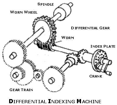
44 11. Helical mill or slab mill is known as the plain milling cutter. 12. Slab milling cutter with fewer teeth is used for heavy-duty work. 13. Side and face cutters are available in diameters up to 200 mm and widths up to 32 mm. On the diameters above 200 mm. The cutters are made with separate inserted teeth. Separate inserted teeth reduce the cost of the cutter and extend the life. Dividing Head or Index Head: Dividing head is a piece of equipment used on machines such as milling, grinding and on drilling machines. The main function of a dividing head is to hold work and to rotate the work a part of a turn for machining operation. This device is used for milling slots, grooves, splines and teeth etc. Parts of Dividing Head Index Centers - work is mounted on index centers. When the index centres rotate the work also rotates. Worm Wheel - worm wheel will have 40 teeth cut on it. Worm Gear - single start worm, Worm and worm wheel help to get finer divisions. Index Plate - Index plate is a circular disc. Index plate has a greater number of circular holes. Holes are equally spaced around the circumference. Plunger lock helps in fixing the pin into any one of the holes of the index plate. Simple Indexing: When crank handle is rotated, the single start worm shaft rotates. The worm shaft is meshed to a 40 teeth worm wheel. Worm wheel is fixed to main spindle. Main spindle carries the work. A milling cutter remains fixed perpendicular to the work piece. When single start worm shaft rotates one rotation, it turns worm wheel by 1 teeth i.e. 40 teeth on worm wheel = teeth on worm wheel = 360/40 = 9 For 2 rotation of worm shaft, rotation of worm wheel = 180 For 3 rotation of worm shaft, rotation of worm wheel = 27 For 6 rotation on worm shaft rotation of worm wheel = 54 For 40 rotation of worm shaft rotation of worm wheel = 360
45 Ex. 1: Cut 18 teeth on the given blank. Use an index plate having 18 holes. The no of teeth required are 18 i.e. to be cut. The no of holes in the index plate = 18 holes. No of rotations the crank has to be turned = = 40 no of teeth to be cut on blank 40 n No. of cranks = Full turn of crank holes refers to holes in index plate 18 This means 2 complete turns 4 holes in an 18-hole circle 40 This division is obtained from index plate containing 18 holes 18 This refers to 4 holes in a circle containing 18 holes Ex. 2: Cut 6 splines on a blank shaft No. of teeth to be cut = 6 No. of turns the crank has to be rotated = 40 n
46 = 6 select index plate having 6 holes no of teeth to be cut on blank 6 6 If index plate with 6 holes is not available, then change to suitable one = This means 6 full & 14 holes in a 21circle index plate Ex. 3: Cut 15 teeth on a gear blank No. of teeth to be cut = 15 No. of turns the crank has to be rotated = 40 = no of teethto be cut n = This means 2 full turn & 10 holes in a 15 hole circle Ex. 4: Mark 48 graduations on a collar No. of graduations to be marked = 48 No. of turns the crank has to be rotated = = no of teethto be cut 48 select index plate having 48 holes If index plate having 48 holes is not available, then simplify as shown below Select index plate having 24 holes in that move by 20 holes Select index plate having 12 holes
47 Select index plate containing 18 holes Note: if the number of divisions does not match one of the hole circles, then factorize the fraction. Select a suitable hole circle maintaining the ratio. It is required to index an angle of 29 degrees 25 minutes and 16 seconds. Make necessary calculations and suggest the necessary gearing between the worm gear spindle & the index plate. Assume reasonably the availability of gears in the shops teeth For turning 1 rotation i.e. 360 of the work, the number of teeth on worm wheel in = 40 teeth Turn of 1 teeth on worm wheel = 9 Turn of 2 teeth on worm wheel = 18 Turn of 3 teeth on worm wheel = 27 For turning through 27 the number of teeth to be turned is 3. For turning through 29, 25 Mins & 16 Secs to be turned 3.26 teeth teeth of worm wheel is turned the work turns through an angle 29, 25 Mins & 16 Secs. 326 To turn 3.26 teeth or teeth of the worm wheel 100
48 full turn and 26 holes in 100 holed plate. Select 100 holed plate and turn 3 times and 26 holes. Select 50 holed plate and turn 3 times and 13 holes Differential Indexing: Differential Indexing is slightly different from simple indexing. A simple indexing consists of index plate; single start worm, worm wheel & main spindle. In differential indexing an additional set of gears is added to the simple indexing setup. Differential indexing is made possible by connecting the index plate to the head stock spindle by means of a gear train. In this the index plate can be made to move either in the same direction (positive) or in the opposite direction (negative) to the index crank. This causes the movement of the index plate to be either faster or slower. Traveling either more or less than the movement of the index crank. Ex. 05: index 77 divisions of a blank 40 No of turns the crank to be rotated = - select an index plate having 77 holes. 77 The index plate will not have 77 hole circle. Therefore we must go for differential indexing. This system is to take an approximate indexing as near as possible to the one required. This will be this is approximate to = - Select 15 hole circle Fix 15 hole index plate 2. In 15 hole circle index plate turn to 8 holes for 1 division to cut 3. In 15 hole circle index plate turn to holes for 2 divisions to cut 4. In 15 hole circle turn to 8 77 holes for 77 divisions to cut 5. To cut 77 division on the blank number of turns the crank has to be turned on a 15 hole circle 77 8 index plate is =
49 Note: In simple indexing one rotation of crank turns worm wheel by 1 teeth. This in turn turns 1 blank attached to main spindle by as the worm wheel has 40 teeth only. 40 Two rotation of crank turn worm wheel by 2 teeth. This turns blank attached to main spindle by 2 40 In this way it is necessary to turn the crank in the index plate by 40 turns only. Because if you turn the crank 40 turns then the worm wheel would have rotated 1 complete rotation and the blank also would have turned one complete rotation. 1 In this problem the crank is rotated by 41 turns by 15 calculations. But in practice the crank 15 has to be turned through 40 turns only. To make the crank turn only 40 turns, then the index plate is made to rotate back, slightly so that 1 the extra 1 turn is avoided. 15 To help facilitate the index plate turn backward or forward, a set of change wheels (gear wheels) is introduced. These Wheels if selected properly with no of idlers can change the direction of rotation of the index plate. 1 To know how the index plate should be rotated backward each rotation. 1 is 15 driver Spindle to plate = = driven Fit the gears in the same way as a compound gear train is fitted in a lathe. The arrangement of gears, change wheels, are shown in fig.
50

51 MODEL I Aim: To fabricate the spur gear model according to the figure given below. Tools required: Milling cutter, Indexing head, Vernier caliper etc. Procedure: 1. Fix the gear blank in milling mandrel between supporting center and Indexing head centre. 2. Fix the milling cutter in Arbor. 3. Calculate indexing for given blank diameter and find out the number of teeth i.e. Z. 4. Bring the cutter near the blank and it should touch the work piece. 5. Give depth of cut by knee elevating handle according to the calculations. 6. Continue this indexing procedure for the required number of teeth and complete the model.
Typical Parts Made with These Processes
 Turning Typical Parts Made with These Processes Machine Components Engine Blocks and Heads Parts with Complex Shapes Parts with Close Tolerances Externally and Internally Threaded Parts Products and Parts
Ahsanullah University of Science and Technology (AUST) Department of Mechanical and Production Engineering
 Department of Mechanical and Production Engineering") Ahsanullah University of Science and Technology (AUST) Department of Mechanical and Production Engineering LABORATORY MANUAL For the students of Department of Mechanical and Production Engineering 1 st
Ahsanullah University of Science and Technology (AUST) Department of Mechanical and Production Engineering LABORATORY MANUAL For the students of Department of Mechanical and Production Engineering 1 st
Chapter 24 Machining Processes Used to Produce Various Shapes.
 Chapter 24 Machining Processes Used to Produce Various Shapes. 24.1 Introduction In addition to parts with various external or internal round profiles, machining operations can produce many other parts
Materials Removal Processes (Machining)
") Chapter Six Materials Removal Processes (Machining) 6.1 Theory of Material Removal Processes 6.1.1 Machining Definition Machining is a manufacturing process in which a cutting tool is used to remove excess
Chapter Six Materials Removal Processes (Machining) 6.1 Theory of Material Removal Processes 6.1.1 Machining Definition Machining is a manufacturing process in which a cutting tool is used to remove excess
ROOP LAL Unit-6 Lathe (Turning) Mechanical Engineering Department
 Mechanical Engineering Department") Notes: Lathe (Turning) Basic Mechanical Engineering (Part B) 1 Introduction: In previous Lecture 2, we have seen that with the help of forging and casting processes, we can manufacture machine parts of
Notes: Lathe (Turning) Basic Mechanical Engineering (Part B) 1 Introduction: In previous Lecture 2, we have seen that with the help of forging and casting processes, we can manufacture machine parts of
1. The Lathe. 1.1 Introduction. 1.2 Main parts of a lathe
 1. The Lathe 1.1 Introduction Lathe is considered as one of the oldest machine tools and is widely used in industries. It is called as mother of machine tools. It is said that the first screw cutting lathe
Lathes. CADD SPHERE Place for innovation Introduction
 Lathes Introduction Lathe is one of the most versatile and widely used machine tools all over the world. It is commonly known as the mother of all other machine tool. The main function of a lathe is to
Turning and Lathe Basics
 Training Objectives After watching the video and reviewing this printed material, the viewer will gain knowledge and understanding of lathe principles and be able to identify the basic tools and techniques
Lathe is a machine, which removes the metal from a piece of work to the required shape & size HENRY MAUDSLAY
 TURNING MACHINES LATHE Introduction Lathe is a machine, which removes the metal from a piece of work to the required shape & size HENRY MAUDSLAY - 1797 Types of Lathe Engine Lathe The most common form
Chapter 22 MACHINING OPERATIONS AND MACHINE TOOLS
 Chapter 22 MACHINING OPERATIONS AND MACHINE TOOLS Turning and Related Operations Drilling and Related Operations Milling Machining Centers and Turning Centers Other Machining Operations High Speed Machining
Lathe. A Lathe. Photo by Curt Newton
 Lathe Photo by Curt Newton A Lathe Labeled Photograph Description Choosing a Cutting Tool Installing a Cutting Tool Positioning the Tool Feed, Speed, and Depth of Cut Turning Facing Parting Drilling Boring
MANUFACTURING TECHNOLOGY
 MANUFACTURING TECHNOLOGY UNIT V Machine Tools Milling cutters Classification of milling cutters according to their design HSS cutters: Many cutters like end mills, slitting cutters, slab cutters, angular
Introduction to Machining: Lathe Operation
 Introduction to Machining: Lathe Operation Lathe Operation Lathe The purpose of a lathe is to rotate a part against a tool whose position it controls. It is useful for fabricating parts and/or features
ME MANUFACTURING TECHNOLOGY LABORATORY-I VARUVAN VADIVELAN INSTITUTE OF TECHNOLOGY DHARMAPURI LAB MANUAL
 VARUVAN VADIVELAN INSTITUTE OF TECHNOLOGY DHARMAPURI 636 703 ME 6311 - MANUFACTURING TECHNOLOGY LABORATORY-I REGULATION 2013 LAB MANUAL BRANCH YEAR / SEM MECHANICAL ENGINEERING II YEAR & III SEMESTER D
TURNING BORING TURNING:
 TURNING BORING TURNING: FACING: Machining external cylindrical and conical surfaces. Work spins and the single cutting tool does the cutting. Done in Lathe. Single point tool, longitudinal feed. Single
 DEPARTMENT OF MECHANICAL ENGINEERING QUESTION BANK ME6402 MANUFACTURING TECHNOLOGY II UNIT I PART A 1. List the various metal removal processes? 2. How chip formation occurs in metal cutting? 3. What is
ROOP LAL Unit-6 (Milling) Mechanical Engineering Department
 Mechanical Engineering Department") Notes: Milling Basic Mechanical Engineering (Part B, Unit - I) 1 Introduction: Milling is a machining process which is performed with a rotary cutter with several cutting edges arranged on the periphery
Notes: Milling Basic Mechanical Engineering (Part B, Unit - I) 1 Introduction: Milling is a machining process which is performed with a rotary cutter with several cutting edges arranged on the periphery
LANDMARK UNIVERSITY, OMU-ARAN
 LANDMARK UNIVERSITY, OMU-ARAN LECTURE NOTE: DRILLING. COLLEGE: COLLEGE OF SCIENCE AND ENGINEERING DEPARTMENT: MECHANICAL ENGINEERING PROGRAMME: MECHANICAL ENGINEERING ENGR. ALIYU, S.J Course code: MCE
COLLEGE OF ENGINEERING MACHINE SHOP FACILITIES AND PRACTICES Prepared by Mike Allen July 31, 2003 Edited by Scott Morton February 18, 2004
 1 COLLEGE OF ENGINEERING MACHINE SHOP FACILITIES AND PRACTICES Prepared by Mike Allen July 31, 2003 Edited by Scott Morton February 18, 2004 I. OBJECTIVE To provide an overview and basic knowledge of the
Summer Junior Fellowship Experience at LUMS. Maliha Manzoor 13 June 15 July, 2011 LUMS Summer Internship
 Summer Junior Fellowship Experience at LUMS Maliha Manzoor 13 June 15 July, 2011 LUMS Summer Internship Internship Schedule June 13-17: 2D and 3D drawings in AutoCAD June 20-24: 2D and 3D drawings in AutoCAD
Lathe Accessories. Work-holding, -supporting, and driving devices
 46-1 Lathe Accessories Divided into two categories Work-holding, -supporting, and driving devices Lathe centers, chucks, faceplates Mandrels, steady and follower rests Lathe dogs, drive plates Cutting-tool-holding
Workshop Practice TA 102 Lec 6 & 7 :Theory of Metal Cutting. By Prof.A.Chandrashekhar
 Workshop Practice TA 102 Lec 6 & 7 :Theory of Metal Cutting By Prof.A.Chandrashekhar Theory of Metal cutting INTRODUCTION: The process of manufacturing a component by removing the unwanted material using
 VALLIAMMAI ENGINEERING COLLEGE DEPARTMENT OF MECHANICAL ENGINEERING QUESTION BANK ME6402 MANUFACTURING TECHNOLOGY II UNIT-I PART A 1. List the various metal removal processes? (BT1) 2. Explain how chip
UNIT 5: Indexing: Simple, compound, differential and angular indexing calculations. Simple problems on simple and compound indexing.
 UNIT 5: Milling machines: Classification, constructional features, milling cutters nomenclature, milling operations, up milling and down milling concepts. Indexing: Simple, compound, differential and angular
Machining Processes Used to Produce Various Shapes. Dr. Mohammad Abuhaiba
 Machining Processes Used to Produce Various Shapes 1 Homework Assignment Due Wensday 28/4/2010 1. Show that the distance lc in slab milling is approximately equal to for situations where D>>d. (see Figure
Metal Cutting - 5. Content. Milling Characteristics. Parts made by milling Example of Part Produced on a CNC Milling Machine 7.
 Content Metal Cutting - 5 Assoc Prof Zainal Abidin Ahmad Dept. of Manufacturing & Industrial Engineering Faculty of Mechanical Engineering Universiti Teknologi Malaysia 7. MILLING Introduction Horizontal
Other Lathe Operations
 Chapter 15 Other Lathe Operations LEARNING OBJECTIVES After studying this chapter, students will be able to: Safely set up and operate a lathe using various work-holding devices. Properly set up steady
AUTOMATED MACHINE TOOLS & CUTTING TOOLS
 CAD/CAM COURSE TOPIC OF DISCUSSION AUTOMATED MACHINE TOOLS & CUTTING TOOLS 1 CNC systems are used in a number of manufacturing processes including machining, forming, and fabrication Forming & fabrication
INDEX. S.No. Name of the Experiment Page No.
 MACHINE TOOLS LAB INDEX S.No. Name of the Experiment Page No. 1 Step Turning and Taper Turning on Lathe 2 Thread Cutting and Knurling on Lathe 3 Machining Flat Surface using Shaper Machine 4 Manufacturing
Machining. Module 6: Lathe Setup and Operations. (Part 2) Curriculum Development Unit PREPARED BY. August 2013
 Curriculum Development Unit PREPARED BY. August 2013") Machining Module 6: Lathe Setup and Operations (Part 2) PREPARED BY Curriculum Development Unit August 2013 Applied Technology High Schools, 2013 Module 6: Lathe Setup and Operations (Part 2) Module Objectives
Machining Module 6: Lathe Setup and Operations (Part 2) PREPARED BY Curriculum Development Unit August 2013 Applied Technology High Schools, 2013 Module 6: Lathe Setup and Operations (Part 2) Module Objectives
Metal Cutting (Machining)
") Metal Cutting (Machining) Metal cutting, commonly called machining, is the removal of unwanted portions from a block of material in the form of chips so as to obtain a finished product of desired size,
Metal Cutting (Machining) Metal cutting, commonly called machining, is the removal of unwanted portions from a block of material in the form of chips so as to obtain a finished product of desired size,
CHAPTER 23 Machining Processes Used to Produce Various Shapes Kalpakjian Schmid Manufacturing Engineering and Technology 2001 Prentice-Hall Page 23-1
 CHAPTER 23 Machining Processes Used to Produce Various Shapes Manufacturing Engineering and Technology 2001 Prentice-Hall Page 23-1 Examples of Parts Produced Using the Machining Processes in the Chapter
Module 1. Classification of Metal Removal Processes and Machine tools. Version 2 ME IIT, Kharagpur
 Module 1 Classification of Metal Removal Processes and Machine tools Lesson 2 Basic working principle, configuration, specification and classification of machine tools Instructional Objectives At the end
STATE UNIVERSITY OF NEW YORK SCHOOL OF TECHNOLOGY CANTON, NEW YORK
 STATE UNIVERSITY OF NEW YORK SCHOOL OF TECHNOLOGY CANTON, NEW YORK COURSE OUTLINE MECH 121 - MANUFACTURING PROCESSES I Prepared By: Daniel Miller Updated By: Daniel Miller (April 2015) CANINO SCHOOL OF
11/15/2009. There are three factors that make up the cutting conditions: cutting speed depth of cut feed rate
 s Geometry & Milling Processes There are three factors that make up the cutting conditions: cutting speed depth of cut feed rate All three of these will be discussed in later lessons What is a cutting
SHAPER, MILLING AND GEAR CUTTING MACHINES
 UNIT 3 SHAPER, MILLING AND GEAR CUTTING MACHINES 1. Compare hydraulic shaper with mechanical shaper? SL.NO Hydrulic shaper Mechanical shaper 1. smooth cutting operation Rough and noisy cutting operation
A H M 531 The Civil Engineering Center
 Title Page Introduction 2 Objectives 2 Theory 2 Fitting 3 Turning 5 Shaping and Grinding 7 Milling 8 Conclusion 11 Reference 11 1 Introduction Machining Machining is a manufacturing process in which a
MILLING and GRINDING MACHINES Machine Tools
 ELEMENTS OF MECHANICAL ENGINEERING PART B UNIT VI MILLING and GRINDING MACHINES Machine Tools 1 Objectives: 1.1 To understand the Principle of working of Milling, Horizontal & Vertical Milling. 1.2 Classification/Types
Module 4 General Purpose Machine Tools. Version 2 ME, IIT Kharagpur
 Module 4 General Purpose Machine Tools Lesson 22 Use of various Attachments in Machine Tools. Instructional objectives At the end of this lesson, the students will be able to; (i) Comprehend and state
TOP WORK ISO 9001.CE UNIVERSAL CUTTER & TOOL GRINDER
 TOP WORK ISO 9001.CE UNIVERSAL CUTTER Precise ball groove of conformation Inclination of Wheelhead The wheelhead can easily tilt up to ±15 degrees, with a 360-degrees swivel on the horizontal plane. The
Turning and Related Operations
 Turning and Related Operations Turning is widely used for machining external cylindrical and conical surfaces. The workpiece rotates and a longitudinally fed single point cutting tool does the cutting.
Tool and Die Maker Level 2
 Level 2 B2 Read and Interpret Drawings II Duration: 32 hours 32 hours 0 hours This unit of instruction introduces the Tool and Die Maker Apprentice with the knowledge and skills necessary to read and interpret
HOW TO USE MILLING MACHINE?
 HOW TO USE MILLING MACHINE? Milling is the process of machining flat, curved, or irregular surfaces by feeding the workpiece against a rotating cutter containing a number of cutting edges. The usual Mill
Cross Peen Hammer. Introduction. Lesson Objectives. Assumptions
 Introduction In this activity plan students will develop various machining and metalworking skills by building a two-piece steel hammer. This project will introduce basic operations for initial familiarization
Chapter 23: Machining Processes: Turning and Hole Making
 Manufacturing Engineering Technology in SI Units, 6 th Edition Chapter 23: Machining Processes: Turning and Hole Making Chapter Outline 1. Introduction 2. The Turning Process 3. Lathes and Lathe Operations
TYPES OF LATHE. Bench lathe It is mounted on bench, and has the same features like engine lathe
 TYPES OF LATHE 1. Speed Lathe a) Wood working b) Centering c) Polishing d) Spinning 2. Engine lathe a) Belt drive b) Individual motor drive c) Gear head lathe 3. Bench lathe 4. Tool room lathe 5. Capstan
Precision made in Germany. As per DIN The heart of a system, versatile and expandable.
 1 Precision made in Germany. As per DIN 8606. The heart of a system, versatile and expandable. Main switch with auto-start protection and emergency off. Precision lathe chuck as per DIN 6386 (Ø 100mm).
MACHINE TOOLS LAB MANUAL. B. Tech III Year - I Semester DEPARTMENT OF MECHANICAL ENGINEERING. Aurora s Technological And Research Institute
 MACHINE TOOLS LAB MANUAL B. Tech III Year - I Semester NAME : ROLL NO : BRANCH : DEPARTMENT OF MECHANICAL ENGINEERING Aurora s Technological And Research Institute Parvathapur, Uppal, Hyderabad-98. 1 MACHINE
The new generation with system accessories. Made in Germany!
 1 The new generation with system accessories. Made in Germany! For face, longitudinal and taper turning, thread-cutting. For machining steel, brass, aluminium and plastic. Mounting flange for fastening
Trade of Toolmaking Module 2: Turning Unit 1: Machine Controls and Operations Phase 2
 Trade of Toolmaking Module 2: Turning Unit 1: Machine Controls and Operations Phase 2 Published by SOLAS 2014 Unit 1 1 Table of Contents Document Release History... 3 Unit Objective... 4 Introduction...
JOB QUALIFICATION STANDARD (JQS)
") Occupation: Work Process: Maintenance Mechanic Machine Shop Practical Hours: 250 hrs. JOB QUALIFICATION STANDARD (JQS) DOL Standard: Manual Machining Fundamentals: Apply a working knowledge of metal removal
Occupation: Work Process: Maintenance Mechanic Machine Shop Practical Hours: 250 hrs. JOB QUALIFICATION STANDARD (JQS) DOL Standard: Manual Machining Fundamentals: Apply a working knowledge of metal removal
Chapter 22: Turning and Boring Processes. DeGarmo s Materials and Processes in Manufacturing
 Chapter 22: Turning and Boring Processes DeGarmo s Materials and Processes in Manufacturing 22.1 Introduction Turning is the process of machining external cylindrical and conical surfaces. Boring is a
THREAD CUTTING & FORMING
 THREAD CUTTING & FORMING Threading, Thread Cutting and Thread Rolling: Machining Threads on External Diameters (shafts) Tapping: Machining Threads on Internal Diameters (holes) Size: Watch to 10 shafts
Lecture 18. Chapter 24 Milling, Sawing, and Filing; Gear Manufacturing (cont.) Planing
 Planing") Lecture 18 Chapter 24 Milling, Sawing, and Filing; Gear Manufacturing (cont.) Planing For production of: Flat surfaces Grooves Notches Performed on long (on average 10 m) workpieces Workpiece moves / Tool
Lecture 18 Chapter 24 Milling, Sawing, and Filing; Gear Manufacturing (cont.) Planing For production of: Flat surfaces Grooves Notches Performed on long (on average 10 m) workpieces Workpiece moves / Tool
MACHINING PROCESSES: TURNING AND HOLE MAKING. Dr. Mohammad Abuhaiba 1
 MACHINING PROCESSES: TURNING AND HOLE MAKING Dr. Mohammad Abuhaiba 1 HoweWork Assignment Due Wensday 7/7/2010 1. Estimate the machining time required to rough cut a 0.5 m long annealed copper alloy round
PLANING MACHINE. Crossrail. Tool head. Table. Table. reciprocating movement Roller. Bed. Open Side Planer Sketch S-8.1-A. Feed screws.
 8 PLANING MACHINE A8.1 : Planing Machine Tool head Table reciprocating movement Roller Table Cross-rail Bed Column Open Side Planer Sketch S-8.1-A Introduction This is also a reciprocating type of machine
BHARATHIDASAN ENGINEERING COLLEGE NATTRAMPALLI DEPARTMENT OF MECHANICAL ENGINEERING LABORATORY MANUAL ME6411-MANUFACTURING TECHNOLOGY LAB- II
 BHARATHIDASAN ENGINEERING COLLEGE NATTRAMPALLI 635 854 DEPARTMENT OF MECHANICAL ENGINEERING LABORATORY MANUAL ME6411-MANUFACTURING TECHNOLOGY LAB- II YEAR / SEMESTER : II / IV DEPARTMENT : Mechanical REGULATION
Milling. Chapter 24. Veljko Samardzic. ME-215 Engineering Materials and Processes
 Milling Chapter 24 24.1 Introduction Milling is the basic process of progressive chip removal to produce a surface. Mill cutters have single or multiple teeth that rotate about an axis, removing material.
Design for machining
 Multiple choice questions Design for machining 1) Which one of the following process is not a machining process? A) Planing B) Boring C) Turning D) Forging 2) The angle made between the rake face of a
Reamer Basics. Fixed Reamers The reamer size is fixed and any size reduction due to wear or sharpening cannot be reclaimed
 1 Reamer Basics Reamers are available in a variety of types, materials, flute styles and sizes The typical reamer is a rotary cutting tools designed to machine a previously formed hole to an exact diameter
UNIT 4: (iii) Illustrate the general kinematic system of drilling machine and explain its working principle
 Illustrate the general kinematic system of drilling machine and explain its working principle") UNIT 4: Drilling machines: Classification, constructional features, drilling & related operations, types of drill & drill bit nomenclature, drill materials. Instructional Objectives At the end of this
UNIT 4: Drilling machines: Classification, constructional features, drilling & related operations, types of drill & drill bit nomenclature, drill materials. Instructional Objectives At the end of this
Machining. Module 5: Lathe Setup and Operations. (Part 1) Curriculum Development Unit PREPARED BY. August 2013
 Curriculum Development Unit PREPARED BY. August 2013") Machining Module 5: Lathe Setup and Operations (Part 1) PREPARED BY Curriculum Development Unit August 2013 Applied Technology High Schools, 2013 Module 5: Lathe Setup and Operations (Part 1) Module Objectives
Machining Module 5: Lathe Setup and Operations (Part 1) PREPARED BY Curriculum Development Unit August 2013 Applied Technology High Schools, 2013 Module 5: Lathe Setup and Operations (Part 1) Module Objectives
Milling Machine Operations
 03/05/2004 TABLE OF CONTENTS Lesson 1 Objectives......3 Vertical Mill 4 Milling Machine Accessories......23 Common Milling Cutters......24 Metal Saws 24 End Mills 25 T-Slot Cutter 25 Dovetail Cutter......25
SHAPING AND PLANING Shaping and planing
 SHAPING AND PLANING Shaping and planing the simplest of all machine operations Straight line cutting motion with single-point cutting tool creates smooth flat surfaces. Mainly plain surfaces are machined
Chapter 24. Machining Processes Used to Produce Various Shapes: Milling
 Chapter 24 Machining Processes Used to Produce Various Shapes: Milling Parts Made with Machining Processes of Chapter 24 Figure 24.1 Typical parts and shapes that can be produced with the machining processes
Drilling. Drilling is the operation of producing circular hole in the work-piece by using a rotating cutter called DRILL.
 Drilling Drilling is the operation of producing circular hole in the work-piece by using a rotating cutter called DRILL. The machine used for drilling is called drilling machine. The drilling operation
Cutting Tools and Cutting materials
 Cutting Tools and Cutting materials Cutting Tools One of most important components in machining process Performance will determine efficiency of operation Two basic types (excluding abrasives) Single point
The new generation with system accessories. Made in Europe!
 1 The new generation with system accessories. Made in Europe! Of cast iron, wide-legged prismatic guide. For vibration-free work even at high loads. Rear flange for mounting the mill/drill head PF 230.
MACHINE TOOLS GRINDING MACHINE TOOLS
 MACHINE TOOLS GRINDING MACHINE TOOLS GRINDING MACHINE TOOLS Grinding in generally considered a finishing operation. It removes metal comparatively in smaller volume. The material is removed in the form
OD1644 MILLING MACHINE OPERATIONS
 SUBCOURSE OD1644 MILLING MACHINE OPERATIONS EDITION 8 US ARMY WARRANT OFFICER ADVANCED COURSE MOS/SKILL LEVEL: 441A MILLING MACHINE OPERATIONS SUBCOURSE NO. OD1644 EDITION 8 US Army Correspondence Course
Review of Various Machining Processes
 Review of Various Machining Processes Digambar O. Jumale 1, Akshay V kharat 2, Akash Tekale 3, Yogesh Sapkal 4,Vinay K. Ghusalkar 5 Department of mechanical engg. 1, 2, 3, 4,5 1, 2, 3, 4,5, PLITMS Buldana
Chapter 25. Other Machining Processes. Materials Processing. MET Manufacturing Processes. Shaping Planing Broaching Sawing Filing
 MET 33800 Manufacturing Processes Chapter 25 Other Machining Processes Before you begin: Turn on the sound on your computer. There is audio to accompany this presentation. Other Machining Processes Shaping
no mm no Dividers with scriber 150 mm NEW Square wedge-shaped knife edges on the length side
 Summer Promotion valid until 30.06.2013 all quoted prices are incl. VAT for deliveries to EU countries to customers with valid VAT-no. and for deliveries in non EU member countries the VAT is not applicable
New. Products2013.
 T u n g a l o y www.tungaloy.com Company Overview Providing Complete Tooling Solutions for the Metal Removal and Industrial Product Sectors TUNGALOY is one of the world s leading manufacturers of carbide
Lecture 15. Chapter 23 Machining Processes Used to Produce Round Shapes. Turning
 Lecture 15 Chapter 23 Machining Processes Used to Produce Round Shapes Turning Turning part is rotating while it is being machined Typically performed on a lathe Turning produces straight, conical, curved,
ROOP LAL Unit-6 Shaper & Planer Mechanical Engineering Department
 Notes: shapers and planers Basic Mechanical Engineering (Part B ) 1 Introduction: Both shapers and planers are machine tools which produce a flat surface. They are capable of machining a horizontal, vertical
MANUFACTURING TECHNOLOGY
 MANUFACTURING TECHNOLOGY UNIT III THEORY OF METAL CUTTING Broad classification of Engineering Manufacturing Processes. It is extremely difficult to tell the exact number of various manufacturing processes
Various other types of drilling machines are available for specialized jobs. These may be portable, bench type, multiple spindle, gang, multiple
 Drilling The process of making holes is known as drilling and generally drilling machines are used to produce the holes. Drilling is an extensively used process by which blind or though holes are originated
Metal Cutting Processes 1 - Turning
 You are here: Home > Handout > Metal Cutting Processes 1 - Turning Metal Cutting Processes 1 - Turning Contents 1. Introduction 2. Center Lathe 3. Cutting Tools 4. Basic Matel Cutting Theory 5. Tool Angles
Rotary Engraving Fact Sheet
 Rotary Engraving Fact Sheet Description Rotary engraving is the term used to describe engraving done with a rotating cutting tool in a motorized spindle. The tool, or cutter, cuts into the surface of the
PRODUCTION ENGINEERING LAB II
 Department of Mechanical Engineering LAB MANUAL FOR PRODUCTION ENGINEERING LAB II DEPT. OF MECHANICAL ENGINEERING 1. SHAPER 1.1 INTRODUCTION The shaper is a reciprocating type of machine tool intended
Chapter 23 Drilling and Hole Making Processes. Materials Processing. Hole Making Processes. MET Manufacturing Processes
 MET 33800 Manufacturing Processes Chapter 23 Drilling and Hole Making Processes Before you begin: Turn on the sound on your computer. There is audio to accompany this presentation. Materials Processing
The new generation with system accessories. Made in Germany!
 1 The new generation with system accessories. Made in Germany! For face, longitudinal and taper turning, thread-cutting. For machining steel, brass, aluminium and plastic. Mounting flange for fastening
Chapter 23: Machining Processes: Hole Making Part A (Lathe Operations, Boring, Reaming, Tapping)
") 1 Manufacturing Processes (2), IE-352 Ahmed M El-Sherbeeny, PhD Spring 2017 Manufacturing Engineering Technology in SI Units, 6 th Edition Chapter 23: Machining Processes: Hole Making Part A (Lathe Operations,
1 Manufacturing Processes (2), IE-352 Ahmed M El-Sherbeeny, PhD Spring 2017 Manufacturing Engineering Technology in SI Units, 6 th Edition Chapter 23: Machining Processes: Hole Making Part A (Lathe Operations,
PREVIEW COPY. Table of Contents. Lesson One Machining Cylindrical Shapes...3. Lesson Two Drilling, Reaming, and Honing...21
 Table of Contents Lesson One Machining Cylindrical Shapes...3 Lesson Two Drilling, Reaming, and Honing...21 Lesson Three Lesson Four Machining Flat Surfaces...37 Determining Tolerances and Finishes...53
Machinist NOA (1998) Subtask to Unit Comparison
 Subtask to Unit Comparison") Machinist NOA (1998) Subtask to Unit Comparison NOA Subtask Task 1 Demonstrates safe working practices. 1.01 Recognizes potential health and safety hazards. A1 Safety in the Machine Shop 1.02 Recognizes
Machinist NOA (1998) Subtask to Unit Comparison NOA Subtask Task 1 Demonstrates safe working practices. 1.01 Recognizes potential health and safety hazards. A1 Safety in the Machine Shop 1.02 Recognizes
MACHINE TOOLS LAB LABORATORY MANUAL
 Vanjari Seethaiah Memorial Engineering College Patancheru, Medak MACHINE TOOLS LAB LABORATORY MANUAL Department of Mechanical Engineering PREFACE Industrial Revolution has given man a lot many luxuries,
MACHINE TOOL ACCESSORIES
 VERTICAL 5-C COLLET VISE SERIES 344: VERTICAL 3-C COLLET VISE SERIES 344: : 2-1/2 x 7-3/4 Height: 4 Small movement of lever opens or closes collet. 2030000 CAM OPERATED 5-C HORIZONTAL/VERTICAL COLLET FIXTURE
أت ارش. Dr. Abdel-Wahab El-Morsy Faculty of Engineering - Rabigh
 Basic Workshop 1 أت ارش Machining Process Machining is a term used to describe a variety of material removal processes in which a cutting tool removes unwanted material from a workpiece to produce the
STEEL RULE. Stock TRY SQUARE
 FITTING INTRODUCTION Fitting consists of a handwork involved in fitting together components usually performed at a bench equipped with a vice and hand tools. The matting components have a close relation
MLR Institute of Technology
 MLR Institute of Technology Dundigal, Quthbullapur (M), Hyderabad 500 043 MECHANICAL ENGINEERING MACHINE TOOLS OBJECTIVE QUESTIONS UNIT - I 1. A built up-edge is formed while machining [ B ] (Sep-2011,
March weeks. surcharge for
 March weeks valid until 31.03.2012 all quoted prices are incl. 19% VAT for deliveries in the EU countries to customers with a valid VAT-no. and for deliveries in not EU member countries the VAT is not
MANUFACTURING TECHNOLOGY
 MANUFACTURING TECHNOLOGY UNIT IV SURFACE FINISHING PROCESS Grinding Grinding is the most common form of abrasive machining. It is a material cutting process which engages an abrasive tool whose cutting
PREVIEW COPY. Table of Contents. Using the Horizontal Milling Machine...3. Lesson Two Slab Milling Procedures...19
 Table of Contents Lesson One Using the Horizontal Milling Machine...3 Lesson Two Slab Milling Procedures...19 Lesson Three Milling Slots and Angles...35 Lesson Four Straddle, Side, and Face Milling...51
Processing and Quality Assurance Equipment
 Processing and Quality Assurance Equipment The machine tool, the wash station, and the coordinate measuring machine (CMM) are the principal processing equipment. These machines provide the essential capability
Useful accessories for lathe and milling systems.
 1 Useful accessories for lathe and milling systems. Nearly all accessories are supplied in wooden boxes. For proper and value preserving storage! Dividing attachment TA 250 For precision lathe PD 250/E,
TRAINING MANUAL. Part INTRODUCTION TO TWIST DRILLS
 PRESTO INTERNATIONAL UK LTD TRAINING MANUAL Part 2 INTRODUCTION TO TWIST DRILLS - 1 - DEFINITION:- A rotary end cutting tool having two or more cutting lips, and having two or more spiral (helical) or
Solid Carbide Thread Milling Cutters
 Solid Carbide Thread Milling Cutters Second Edition Thread milling cutters by Features and Benefits: Sub-micro grain carbide substrate Longer tool life with tighter tolerances More cost-effective than
Sheet Metal Tools. by:prem Mahendranathan
 Sheet Metal Tools by: SHEET METAL TOOL KIT SHEET METAL TOOLS Rivet Gun 3/32, 1/8, 5/32, 3/16",Cupped Set Mini Bucking Bar Footed Heel-Toe Bucking Bar Air Tool Oil Mechanics Tool Bag High-Speed Air Drill
Chapter 24. Machining Processes Used to Produce Various Shapes: Milling, Broaching, Sawing, and Filing; Gear Manufacturing
 Chapter 24 Machining Processes Used to Produce Various Shapes: Milling, Broaching, Sawing, and Filing; Gear Manufacturing Parts Made with Machining Processes of Chapter 24 Figure 24.1 Typical parts and