Cutting Tools and Cutting materials
|
|
|
- Gavin Cross
- 5 years ago
- Views:
Transcription
1 Cutting Tools and Cutting materials
2 Cutting Tools One of most important components in machining process Performance will determine efficiency of operation Two basic types (excluding abrasives) Single point and multiple point Must have rake and clearance angles ground or formed on them
3 Cutting-Tool Materials Toolbits generally made of seven materials High-speed steel Cast alloys (such as stellite) Cemented carbides Ceramics Cermets Cubic Boron Nitride Polycrystalline Diamond
4 Cutting Tool Properties Hardness Cutting tool material must be 1 1/2 times harder than the material it is being used to machine. Capable of maintaining a red hardness during machining operation Red hardness: ability of cutting tool to maintain sharp cutting edge Also referred to as hot hardness or hot strength
5 Cutting Tool Properties Wear Resistance Able to maintain sharpened edge throughout the cutting operation Same as abrasive resistance Shock Resistance Able to take the cutting loads and forces Shape and Configuration Must be available for use in different sizes and shapes.
6 High-Speed Steel May contain combinations of tungsten, chromium, vanadium, molybdenum, cobalt Can take heavy cuts, withstand shock and maintain sharp cutting edge under red heat Generally two types (general purpose) Molybdenum-base (Group M) Tungsten-base (Group T) Cobalt added if more red hardness desired
7 Cast Alloy Usually contain 25% to 35% chromium, 4% to 25% tungsten and 1% to 3% carbon Remainder cobalt Qualities High hardness High resistance to wear Excellent red-hardness Operate 2 ½ times speed of high-speed steel Weaker and more brittle than high-speed steel
8 Carbide Cutting Tools First used in Germany during WW II as substitute for diamonds Various types of cemented (sintered) carbides developed to suit different materials and machining operations Good wear resistance Operate at speeds ranging 150 to 1200 sf/min Can machine metals at speeds that cause cutting edge to become red hot without loosing harness
9 Manufacture of Cemented Carbides Products of powder metallurgy process Tantalum, titanium, niobium Operations Blending Compaction Presintering Sintering
10 Types of Carbide Lathe Cutting Tools Blazed-tip type Cemented-carbide tips brazed to steel shanks Wide variety of styles and sizes Indexable insert type Throwaway inserts Wide variety of shapes: triangular, square, diamond, and round Triangular: has three cutting edges Inserts held mechanically in special holder
11 Tool Geometry Terms adopted by ASME SIDE RELIEF SIDE CLEARANCE Copyright The McGraw-Hill Companies, Inc. Permission required for reproduction or display.
12 Cutting-Tool Terms Front, End, Relief (Clearance) Allows end of cutting tool to enter work Side Relief (Side) Permits side of tool to advance into work Copyright The McGraw-Hill Companies, Inc. Permission required for reproduction or display.
13 Cutting-Tool Terms Side Cutting Edge Angle Angle cutting edge meets work Positive Negative - protects point at start and end of cut Nose Radius Strengthens finishing point of tool Improves surface finish on work Should be twice amount of feed per revolution Too large chatter; too small weakens point

14 Side Rake Large as possible to allow chips to escape Amount determined Type and grade of cutting tool Type of material being cut Feed per revolution Angle of keenness Formed by side rake and side clearance Copyright The McGraw-Hill Companies, Inc. Permission required for reproduction or display.

15 Back Rake Angle formed between top face of tool and top of tool shank Positive Top face slopes downward away from point Negative Top face slopes upward away from point Neutral Copyright The McGraw-Hill Companies, Inc. Permission required for reproduction or display.
16 Cutting Speeds and Feeds Important factors that influence speeds, feeds, and depth of cut Type and hardness of work material Grade and shape of cutting tool Rigidity of cutting tool Rigidity of work and machine Power rating of machine

17
18 Lathe is one of the oldest important machine tools in the metal working industry. A lathe operates on the principle of a rotating work piece and a fixed cutting tool. A rope wound round the work with its own end attached to a flexible branch of tree and other end being pulled by man caused job to rotate intermittently. With its further development a strip of wood called lath was used to support the rope and that is how the machine came to be known as lathe. The cutting tool is feed into the workpiece, which rotates about its own axis, causing the workpiece to be formed to the desired shape. Lathe machine is also known as the mother/father of the entire tool family.
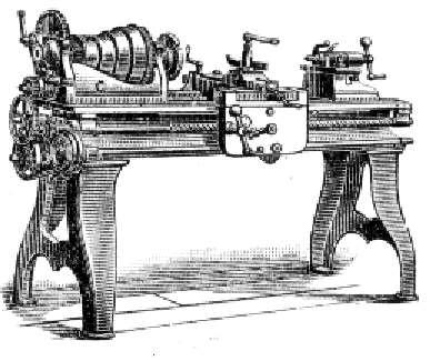
19 The Lathe Machine is one of the oldest and most important machine tools. As early as 1569, wood lathes were in use in France. The lathe machine was adapted to metal cutting in England during the Industrial Revolution. Lathe machine also called Engine Lathe because the first type of lathe was driven by a steam engine.

20 Henry Maudsley was born on an isolated farm near Gigghleswick in North Yorkshire and educated at University Collage London. He was an outstandingly brilliant medical student, collecting ten Gold Medals and graduating with an M.D. degree in 1857.

21

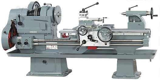
22 This term engine is associated with the lathe owing to the fact that early lathes were driven by steam engine. It is also called centre lathe. The most common form of lathe, motor driven and comes in large variety of sizes and shapes.
23 Engine lathes are classified according to the various designs of headstock and methods of transmitting power to the machine. 1. Belt Driven Lathe 2. Motor Driven Lathe 3. Gear Head Lathe The power to the engine lathe spindle may be given with the help of a belt drive from an overhead line shaft but most modern machines have a captive motor with either a cone pulley driven or an geared headstock arrangement.

24 A bench top model usually of low power used to make precision machine small work pieces. It is used for small w/p having a maximum swing of 250 mm at the face plate. Practically it consists of all the parts of engine lathe or speed lathe.

25 A lathe that has the ability to follow a template to copy a shape or contour.

26 A tool room lathe having features similar to an engine lathe is much more accurately built and has a wide range of spindle speeds ranging from a very low to a quite high speed up to 2500 rpm. This lathe is mainly used for precision work on a tools, dies, gauges, and in machining work where accuracy is needed. This lathe machine is costlier than an engine lathe of the same size.

27 A lathe in which the work piece is automatically fed and removed without use of an operator. It requires very less attention after the setup has been made and the machine loaded.
.")
28 Turret lathe is the adaptation of the engine lathe where the tail stock is replaced by a turret slide(cylindrical or hexagonal). Tool post of the engine lathe is replaced by a square cross slide which can hold four tools.
29 It has heavier construction and provides wider range of speeds. The saddle carrying the turret head moves along the whole length of the bed. Much longer jobs can be machined. Turret head directly mounted on the saddle. The front tool post can carry 4 tools and rear tool post may have 1 or 2 tools. Turret may have4 to 6 tools. More than one tool may be set to operate simultaneously. There is no lead screw.

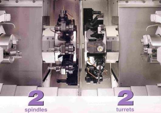
30 A highly automated lathe, where both cutting, loading, tool changing, and part unloading are automatically controlled by computer coding. E.g. CNC Lathe M/C.(Computer Numerical Control Machine)
31
32
33

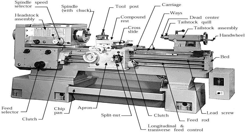
34 This is heavy rugged casting made to support the working parts of lathe and also guide and align major parts of lathe. Made to support working parts of lathe. On top section are machined ways. Guide and align major parts of lathe.

35 The headstock houses the main spindle,speed change mechanism, and change gears. The headstock is required to be made as robust as possible due to the cutting forces involved,which can distort a lightly built housing.

36 Induce harmonic vibrations that will transfer through the work piece, reducing the quality of the finished work piece.

37 Contains number of different-size gears. Provides feed rod and lead-screw with various speeds for turning and thread-cutting operations TOP VIEW
38 The arrangement which are employed in feed gear boxes to obtain multispindle speeds and different rates of feeds are: I. Sliding Gear Mechanism II. III. Sliding Clutch Mechanism Gear Cone And Tumbler Gear Mechanism IV. Sliding Key Mechanism V. Combination of any two or more of the above Usually two or three levers must be moved to obtain the desired combination within a given range.

39 Used to move cutting tool along lathe bed. Consists of three main partsi. Saddle ii. Cross-slide iii. Apron
40 Movement of entire carriage assembly along the bed provides feed for the tool parallel to the lathe axis. The compound rest can be swivelled on the cross slide in the horizontal plane about vertical axis. To the front of the carriage is attached the apron. It is fastened to the saddle and hangs over the front of the bed. The apron houses the automatic feed mechanism for longitudinal and cross feeds and the split nut for thread cutting.

41 Mounted on top of saddle. Provides manual or automatic cross movement for cutting tool.

42 Fastened to saddle. Houses gears and mechanism required to move carriage or crossslide automatically. Locking-off lever inside apron prevents engaging split-nut lever and automatic feed lever at same time. Apron hand wheel turned manually to move carriage along lathe bed

43 Upper and lower tailstock castings. Adjusted for taper or parallel turning by two screws set in base. Tailstock clamp locks tailstock in any position along bed of lathe. Tailstock spindle has internal taper to receive dead center. Provides support for right-hand end of work.
44 In tail stock jobs of different lengths are provided with quill which can be moved in and out by means of a screw and then locked in position. The movement of the quill is parallel to the lathe axis. The quill has a tapered bore into which is fitted a hardened centre which locates and holds the w/p when turning between centre. This bore may also be used for supporting tools for operations like drilling and reaming.
45 Engages clutch that provides automatic feed to carriage. Feed-change lever can be set for longitudinal feed or for cross-feed. In neutral position, permits split-nut lever to be engaged for thread cutting. Carriage moved automatically when split-nut lever engaged
46 Distance carriage will travel in one revolution of spindle. Depends on speed of feed rod or lead screw. Controlled by change gears in quick-change gearbox. Obtains drive from headstock spindle through end gear train. Chart mounted on front of quick-change gearbox indicates various feeds.
47
 A push-out type collet.")
48 (a) and (b) Schematic illustrations of a draw-in-type collets. (c) A push-out type collet. (d) Workholding of a part on a face plate.


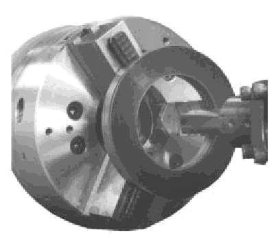
49 - Forholding cylindrical stock centered. - For facing/center drilling etc. - This is independent chuck generally has four jaws, which are adjusted individually on the chuck face by means of adjusting screws.


50 -Collet chuck is used to hold small work pieces. -Thin jobs can be held by means of magnetic chucks.
51 Don t touch cutter or chips while machine is running. Make sure work is clamped tightly in chuck or collet. Be careful to stay clear of chuck jaws.

52 All lathe operators must be constantly aware of the safety. Handle sharp cutters, centres, and drills with care. Remove chuck keys and wrenches before operating. Always wear protective eye protection. Always stop the lathe before making adjustments. Know where the emergency stop is before operating the lathe. Correct dress is important, remove rings and watches. Do not change spindle speeds until the lathe comes to a complete stop.
53 Lathes are highly accurate machine tools designed to operate around the clock if properly operated and maintained. Lathes must be lubricated and checked for adjustment before operation. Improper lubrication or loose nuts and bolts can cause excessive wear and dangerous operating conditions.
54 Drilling machine

55 Introduction Drilling is a metal cutting process carried out by a rotating cutting tool to make circular holes in solid materials. Tool which makes hole is called as drill bit or twist drill.
56 Drilling machine A power operated machine tool which holds the drill in its spindle rotating at high speeds and when actuated move linearly against the work piece produces a hole.
57 Types of drilling machine. Portable drilling machine Bench drilling machine Radial drilling machine Pillar drilling machine Gang drilling machine Multiple drilling machine

58 Portable drilling machine
59 Bench drilling machine These are light duty machines used in small workshops. Also called Sensitive drilling machines because of its accurate and well balanced spindle. Holes of diameter 1 mm to 15 mm.
60 Bench drilling machine
61 parts Vertical main column Base Moving drill head Work table Electric motor Variable speed gear box and spindle feed mechanism.
62 working Work piece with the exact location marked on it with the centre punch is clamped rigidly on the work table. spindle axis and center punch indentation are in same line. Machine is started and drill bit is lowered by rotating feed handle. Drill bit touches the work and starts removing material.

63 Bench drilling machine
64 Radial drilling machine These are heavy duty and versatile drilling machine used to perform drilling operate on large and heavy work piece. Holes up to 7.5 cm.
65 Radial drilling machine

66 parts Heavy base Vertical column Horizontal arm Drilling head
67 working Work piece is marked for exact location and mounted on the work table. Drill bit is then located by moving the radial arm and drill to the marked location. By starting drill spindle motor holes are drilled.
68 Drilling machine operation Reaming Boring Counter boring Counter sinking Spot facing Tapping
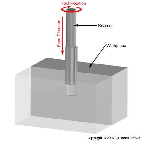
69 Reaming It is a process of smoothing the surface of drilled holes with a tool. Tool is called as reamer. Initially a hole is drilled slightly smaller in size. Drill is replaced by reamer. Speed is reduced to half that of the drilling.
70 Reaming
71 Boring It is process carried on a drilling machine to increase the size of an already drilled hole. Initially a hole is drilled to the nearest size and using a boring tool the size of the hole is increased.

72 This process involves increasing the size of a hole at only one end. Cutting tool will have a small cylindrical portion called pilot. Cutting speed = twothirds of the drilling speed for the same hole. Counter boring

73 Counter sinking This is an operation of making the end of a hole into a conical shape. Cutting speed = half of the cutting speed of drilling for same hole.

74 Spot facing It is a finishing operation to produce flat round surface usually around a drilled hole, for proper seating of bolt head or nut. It is done using a special spot facing tool.
75
76 Tapping Process of cutting internal threads with a thread tool called as tap. Tap is a fluted threaded tool used for cutting internal thread Cutting speed is very slow.
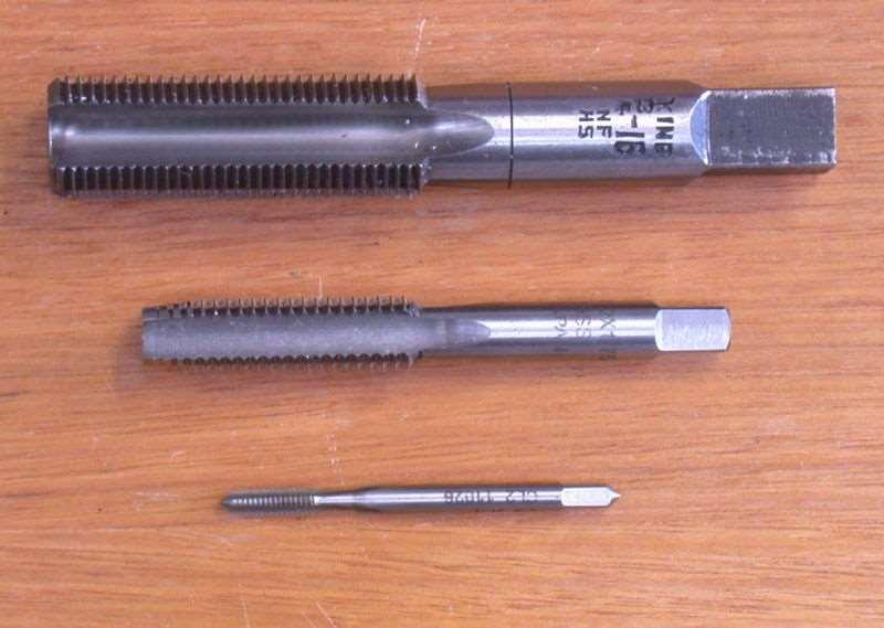
77
78 Specification of a radial drilling Power capacity eg: 1.5 hp for drilling motor and 0.5 hp for elevating motor. The range of speed of spindle eg: 50 to 2800 rpm. machine
79 Length of arm on which drill head can traverse. eg: 600 mm. Vertical movement of the arm eg: 500 mm. Angular swing of arm eg: 360
80 Boring Machine In machining, boring is the process of enlarging a hole that has already been drilled (or cast), by means of a single-point cutting tool (or of a boring head containing several such tools), for example as in boring a cannon barrel. Boring is used to achieve greater accuracy of the diameter of a hole, and can be used to cut a tapered hole.

81 Boring machine
82 TYPES OF BORING There are various types of boring. The boring bar may be supported on both ends (which only works if the existing hole is a through hole), or it may be supported at one end. Lineboring (line boring, line-boring) implies the former. Backboring (back boring, backboring) is the process of reaching through an existing hole and then boring on the "back" side of the workpiece (relative to the machine headstock).
83 The two types of the boring machine, each of which has several varieties, are the horizontal boring and drilling machine, and the vertical boring and turning mill.

84 HORIZONTAL BORING MACHINE

85 VERTICAL BORING MACHINE

86 JIG BORING MACHINE

87 Floor Type Horizontal Boring Machine

88 Vertical boring machine
89 METHODS OF LOCATING HOLES IN JIG BORING M/CS Lead Screw Method Mechanical and electrical gauging Optical Measuring Method
90 Jigs and Fixtures


91 Definitions Jig: A device that holds the work and locates the path of the tool. Fixture: A device fixed to the worktable of a machine and locates the work in an exact position relative to the cutting tool. Superior Jig Flexible Fixturing Systems

92 What are Jigs and Fixtures Anything used to hold a work piece in a desired location Locate parts for precision Repeating process on a series of parts Holding parts for machining, painting, assembly


93 Two main types of jigs: For machining purposes Locates the component, holds it firmly in place, and guides the cutting tool. For assembly purposes Locates separate component parts and holds them rigidly in their correct positions while they are being connected. Northwestern Tools
 The simplest type of drill jig")

94 Drill jig terms Open jig (also called plate jig or drill template) The simplest type of drill jig Consists of a plate with holes to guide the drills, and may have locating pins that locate the workpiece on the jig

95 Drill jig terms Drill bushings Precision tools that guide cutting tools such as drill and reamers into precise locations in a workpiece. Accurate Bushing Co.

96 Drill jig components Jig body Holds the various parts of a jig assembly. Cap screws and dowel pins Hold fabricated parts together

97 Drill jig components Locating devices Pins, pads, and recesses used to locate the workpiece on the jig.

98 Drill jig components Clamping devices

99 Drill jig components Locking pins Inserted to lock or hold the work piece securely to the jig plate while subsequent holes are being drilled.
100 Uses of Jig and fixture Reduce cost of production. Increase the production. To assure high accuracy of parts Provide for interchangeability Enable heavy and complex parts to machine Reduced quality control expenses. Increased versatility of machine tool. Less skilled labour. Saving labour. Partially automates the machine tools Use improve the safety, accidents low
101 Elements of Jig and fixture Sufficiently rigid bodies (plate, box or frame structure Locating elements. Clamping elements. Tool guiding elements. Elements for positioning or fastening the jig or fixture.

102 Dimensioning Jig Drawings

103 Designing jigs Jigs can also be designed as per requirement of the workpiece for holding and other machining operations. Northwestern Tools

104 Type of Fixtures Milling fixtures Fixture components Fixture design considerations Sequence in laying out a fixture Standard Parts Co.

105 Fixture components Fixture base Standard Parts Co. Fixture components and the workpiece are usually located on a base, which is securely fastened to the milling machine table.

106 Fixture components Clamps American Drill Bushing Co. Clamps counteract forces from the feed of the table and rotation of the cutter.

107 Fixture components Set blocks Cutter set blocks are mounted on the fixture to properly position the milling cutter in relation to the workpiece.
108 Basic Categories of Jigs Clamps Chucks Vises Bushings Modular Fixtures
109 Clamps
110 Chucks
111 Vises
112 Bushings
113 Modular Fixturing
114 Application
115 Resources Catalogs Websites Journal Articles
116

117 Jigs and Fixtures

118 V-location In V-location, work pieces having circular or semicircular profile are located by means of a Vee block. The block should be used accurately so that the variation in the work piece size are not detrimental to location.
119 Vee can be used for both locating and clamping purpose for this two Vee can be used, one fixed other sliding one. Fixed Vee is used for locating and sliding one for clamping.
120 The sliding Vee block may be actuated by means of a hand operated screw.

121 Bush location Shaft type work pieces can be easily locate in a hardened steel bushes. The bushes can be plain or flanged type. A flange straighten the bush and also prevent it from being driven into the jig body if it is left unlocked.
122 Design principles of location purpose The following principles should be followed while locating surfaces. 1.At least one datum or reference surface should be established at the first opportunity. 2. For ease of cleaning, locating surfaces should be as small as possible. 3. The locating surfaces should not hold swarf and thereby misalign the workpiece
123
124 4.Locating surfaces should be raised above surrounding surfaces of the jigs or fixture. 5. Sharp corners in the locating surfaces must be avoided. 6. Adjustable type of locaters should be used for the location on rough surfaces.
125 7. Locating pins should be easily accessible and visible to the operator. 8. To avoid distortion of the work, it should be supported as shown in fig.
Turning and Lathe Basics
 Training Objectives After watching the video and reviewing this printed material, the viewer will gain knowledge and understanding of lathe principles and be able to identify the basic tools and techniques
TURNING BORING TURNING:
 TURNING BORING TURNING: FACING: Machining external cylindrical and conical surfaces. Work spins and the single cutting tool does the cutting. Done in Lathe. Single point tool, longitudinal feed. Single
Lathe is a machine, which removes the metal from a piece of work to the required shape & size HENRY MAUDSLAY
 TURNING MACHINES LATHE Introduction Lathe is a machine, which removes the metal from a piece of work to the required shape & size HENRY MAUDSLAY - 1797 Types of Lathe Engine Lathe The most common form
ROOP LAL Unit-6 Lathe (Turning) Mechanical Engineering Department
 Mechanical Engineering Department") Notes: Lathe (Turning) Basic Mechanical Engineering (Part B) 1 Introduction: In previous Lecture 2, we have seen that with the help of forging and casting processes, we can manufacture machine parts of
Notes: Lathe (Turning) Basic Mechanical Engineering (Part B) 1 Introduction: In previous Lecture 2, we have seen that with the help of forging and casting processes, we can manufacture machine parts of
Typical Parts Made with These Processes
 Turning Typical Parts Made with These Processes Machine Components Engine Blocks and Heads Parts with Complex Shapes Parts with Close Tolerances Externally and Internally Threaded Parts Products and Parts
Turning and Related Operations
 Turning and Related Operations Turning is widely used for machining external cylindrical and conical surfaces. The workpiece rotates and a longitudinally fed single point cutting tool does the cutting.
1. The Lathe. 1.1 Introduction. 1.2 Main parts of a lathe
 1. The Lathe 1.1 Introduction Lathe is considered as one of the oldest machine tools and is widely used in industries. It is called as mother of machine tools. It is said that the first screw cutting lathe
Lathe. A Lathe. Photo by Curt Newton
 Lathe Photo by Curt Newton A Lathe Labeled Photograph Description Choosing a Cutting Tool Installing a Cutting Tool Positioning the Tool Feed, Speed, and Depth of Cut Turning Facing Parting Drilling Boring
LANDMARK UNIVERSITY, OMU-ARAN
 LANDMARK UNIVERSITY, OMU-ARAN LECTURE NOTE: DRILLING. COLLEGE: COLLEGE OF SCIENCE AND ENGINEERING DEPARTMENT: MECHANICAL ENGINEERING PROGRAMME: MECHANICAL ENGINEERING ENGR. ALIYU, S.J Course code: MCE
Introduction to Machining: Lathe Operation
 Introduction to Machining: Lathe Operation Lathe Operation Lathe The purpose of a lathe is to rotate a part against a tool whose position it controls. It is useful for fabricating parts and/or features
Drilling. Drilling is the operation of producing circular hole in the work-piece by using a rotating cutter called DRILL.
 Drilling Drilling is the operation of producing circular hole in the work-piece by using a rotating cutter called DRILL. The machine used for drilling is called drilling machine. The drilling operation
MACHINING PROCESSES: TURNING AND HOLE MAKING. Dr. Mohammad Abuhaiba 1
 MACHINING PROCESSES: TURNING AND HOLE MAKING Dr. Mohammad Abuhaiba 1 HoweWork Assignment Due Wensday 7/7/2010 1. Estimate the machining time required to rough cut a 0.5 m long annealed copper alloy round
Lathes. CADD SPHERE Place for innovation Introduction
 Lathes Introduction Lathe is one of the most versatile and widely used machine tools all over the world. It is commonly known as the mother of all other machine tool. The main function of a lathe is to
Lathe Accessories. Work-holding, -supporting, and driving devices
 46-1 Lathe Accessories Divided into two categories Work-holding, -supporting, and driving devices Lathe centers, chucks, faceplates Mandrels, steady and follower rests Lathe dogs, drive plates Cutting-tool-holding
UNIT 4: (iii) Illustrate the general kinematic system of drilling machine and explain its working principle
 Illustrate the general kinematic system of drilling machine and explain its working principle") UNIT 4: Drilling machines: Classification, constructional features, drilling & related operations, types of drill & drill bit nomenclature, drill materials. Instructional Objectives At the end of this
UNIT 4: Drilling machines: Classification, constructional features, drilling & related operations, types of drill & drill bit nomenclature, drill materials. Instructional Objectives At the end of this
Machining. Module 6: Lathe Setup and Operations. (Part 2) Curriculum Development Unit PREPARED BY. August 2013
 Curriculum Development Unit PREPARED BY. August 2013") Machining Module 6: Lathe Setup and Operations (Part 2) PREPARED BY Curriculum Development Unit August 2013 Applied Technology High Schools, 2013 Module 6: Lathe Setup and Operations (Part 2) Module Objectives
Machining Module 6: Lathe Setup and Operations (Part 2) PREPARED BY Curriculum Development Unit August 2013 Applied Technology High Schools, 2013 Module 6: Lathe Setup and Operations (Part 2) Module Objectives
Ahsanullah University of Science and Technology (AUST) Department of Mechanical and Production Engineering
 Department of Mechanical and Production Engineering") Ahsanullah University of Science and Technology (AUST) Department of Mechanical and Production Engineering LABORATORY MANUAL For the students of Department of Mechanical and Production Engineering 1 st
Ahsanullah University of Science and Technology (AUST) Department of Mechanical and Production Engineering LABORATORY MANUAL For the students of Department of Mechanical and Production Engineering 1 st
Module 1. Classification of Metal Removal Processes and Machine tools. Version 2 ME IIT, Kharagpur
 Module 1 Classification of Metal Removal Processes and Machine tools Lesson 2 Basic working principle, configuration, specification and classification of machine tools Instructional Objectives At the end
Chapter 22: Turning and Boring Processes. DeGarmo s Materials and Processes in Manufacturing
 Chapter 22: Turning and Boring Processes DeGarmo s Materials and Processes in Manufacturing 22.1 Introduction Turning is the process of machining external cylindrical and conical surfaces. Boring is a
Chapter 22 MACHINING OPERATIONS AND MACHINE TOOLS
 Chapter 22 MACHINING OPERATIONS AND MACHINE TOOLS Turning and Related Operations Drilling and Related Operations Milling Machining Centers and Turning Centers Other Machining Operations High Speed Machining
ROOP LAL Unit-6 Drilling & Boring Mechanical Engineering Department
 Lecture 4 Notes : Drilling Basic Mechanical Engineering ( Part B ) 1 Introduction: The process of drilling means making a hole in a solid metal piece by using a rotating tool called drill. In the olden
Chapter 23: Machining Processes: Turning and Hole Making
 Manufacturing Engineering Technology in SI Units, 6 th Edition Chapter 23: Machining Processes: Turning and Hole Making Chapter Outline 1. Introduction 2. The Turning Process 3. Lathes and Lathe Operations
Various other types of drilling machines are available for specialized jobs. These may be portable, bench type, multiple spindle, gang, multiple
 Drilling The process of making holes is known as drilling and generally drilling machines are used to produce the holes. Drilling is an extensively used process by which blind or though holes are originated
ME MANUFACTURING TECHNOLOGY LABORATORY-I VARUVAN VADIVELAN INSTITUTE OF TECHNOLOGY DHARMAPURI LAB MANUAL
 VARUVAN VADIVELAN INSTITUTE OF TECHNOLOGY DHARMAPURI 636 703 ME 6311 - MANUFACTURING TECHNOLOGY LABORATORY-I REGULATION 2013 LAB MANUAL BRANCH YEAR / SEM MECHANICAL ENGINEERING II YEAR & III SEMESTER D
Trade of Toolmaking Module 2: Turning Unit 1: Machine Controls and Operations Phase 2
 Trade of Toolmaking Module 2: Turning Unit 1: Machine Controls and Operations Phase 2 Published by SOLAS 2014 Unit 1 1 Table of Contents Document Release History... 3 Unit Objective... 4 Introduction...
Machining. Module 5: Lathe Setup and Operations. (Part 1) Curriculum Development Unit PREPARED BY. August 2013
 Curriculum Development Unit PREPARED BY. August 2013") Machining Module 5: Lathe Setup and Operations (Part 1) PREPARED BY Curriculum Development Unit August 2013 Applied Technology High Schools, 2013 Module 5: Lathe Setup and Operations (Part 1) Module Objectives
Machining Module 5: Lathe Setup and Operations (Part 1) PREPARED BY Curriculum Development Unit August 2013 Applied Technology High Schools, 2013 Module 5: Lathe Setup and Operations (Part 1) Module Objectives
Precision made in Germany. As per DIN The heart of a system, versatile and expandable.
 1 Precision made in Germany. As per DIN 8606. The heart of a system, versatile and expandable. Main switch with auto-start protection and emergency off. Precision lathe chuck as per DIN 6386 (Ø 100mm).
TU-3008G-16M - Opti-Turn Lathe & Mill Drill Combination Package Deal 300 x 700mm Included BF-16AV Mill Head
 TU-3008G-16M - Opti-Turn Lathe & Mill Drill Combination Package Deal 300 x 700mm Included BF-16AV Mill Head Package Deal Ex GST Inc GST $3,980.00 $4,577.00 Package Contents - SAVE $402.50 (Inc) 1 x L691
The new generation with system accessories. Made in Germany!
 1 The new generation with system accessories. Made in Germany! For face, longitudinal and taper turning, thread-cutting. For machining steel, brass, aluminium and plastic. Mounting flange for fastening
Summer Junior Fellowship Experience at LUMS. Maliha Manzoor 13 June 15 July, 2011 LUMS Summer Internship
 Summer Junior Fellowship Experience at LUMS Maliha Manzoor 13 June 15 July, 2011 LUMS Summer Internship Internship Schedule June 13-17: 2D and 3D drawings in AutoCAD June 20-24: 2D and 3D drawings in AutoCAD
Drilling. Drilling is the operation of producing circular hole in the work-piece by using a rotating cutter called DRILL.
 Drilling Machine Drilling Drilling is the operation of producing circular hole in the work-piece by using a rotating cutter called DRILL. The machine used for drilling is called drilling machine. The drilling
Turning. MECH Dr Ghassan Al-Kindi - Lecture 10 1
 Turning Single point cutting tool removes material from a rotating workpiece to generate a cylinder Performed on a machine tool called a lathe Variations of turning performed on a lathe: Facing Contour
TU-3008G-20M - Opti-Turn Lathe & Mill Drill Combination Package Deal 300 x 700mm Included BF-20AV Mill Head
 TU-3008G-20M - Opti-Turn Lathe & Mill Drill Combination Package Deal 300 x 700mm Included BF-20AV Mill Head Package Deal Ex GST Inc GST $3,850.00 $4,235.00 Package Contents - SAVE $209.00 (Inc) 1 x L691
PLANING MACHINE. Crossrail. Tool head. Table. Table. reciprocating movement Roller. Bed. Open Side Planer Sketch S-8.1-A. Feed screws.
 8 PLANING MACHINE A8.1 : Planing Machine Tool head Table reciprocating movement Roller Table Cross-rail Bed Column Open Side Planer Sketch S-8.1-A Introduction This is also a reciprocating type of machine
TOP WORK ISO 9001.CE UNIVERSAL CUTTER & TOOL GRINDER
 TOP WORK ISO 9001.CE UNIVERSAL CUTTER Precise ball groove of conformation Inclination of Wheelhead The wheelhead can easily tilt up to ±15 degrees, with a 360-degrees swivel on the horizontal plane. The
Workshop Practice TA 102 Lec 6 & 7 :Theory of Metal Cutting. By Prof.A.Chandrashekhar
 Workshop Practice TA 102 Lec 6 & 7 :Theory of Metal Cutting By Prof.A.Chandrashekhar Theory of Metal cutting INTRODUCTION: The process of manufacturing a component by removing the unwanted material using
Tool and Die Maker Level 2
 Level 2 B2 Read and Interpret Drawings II Duration: 32 hours 32 hours 0 hours This unit of instruction introduces the Tool and Die Maker Apprentice with the knowledge and skills necessary to read and interpret
Cross Peen Hammer. Introduction. Lesson Objectives. Assumptions
 Introduction In this activity plan students will develop various machining and metalworking skills by building a two-piece steel hammer. This project will introduce basic operations for initial familiarization
COLLEGE OF ENGINEERING MACHINE SHOP FACILITIES AND PRACTICES Prepared by Mike Allen July 31, 2003 Edited by Scott Morton February 18, 2004
 1 COLLEGE OF ENGINEERING MACHINE SHOP FACILITIES AND PRACTICES Prepared by Mike Allen July 31, 2003 Edited by Scott Morton February 18, 2004 I. OBJECTIVE To provide an overview and basic knowledge of the
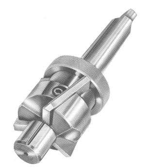
Reamer Basics. Fixed Reamers The reamer size is fixed and any size reduction due to wear or sharpening cannot be reclaimed
 1 Reamer Basics Reamers are available in a variety of types, materials, flute styles and sizes The typical reamer is a rotary cutting tools designed to machine a previously formed hole to an exact diameter
TU-3008G - Opti-Turn Bench Lathe 300 x 700mm Turning Capacity Geared Head-Stock & Enclosed Gearbox
 TU-3008G - Opti-Turn Bench Lathe 300 x 700mm Turning Capacity Geared Head-Stock & Enclosed Gearbox Ex GST Inc GST $3,460.00 $3,979.00 ORDER CODE: MODEL: Swing Over Bed (mm): Distance Between Centres (mm):
C SERIES LATHES AFFORDABLE. DURABLE. VERSATILE. A line of precision, high performance geared head and variable speed lathes. TURNING PRODUCT CATALOG
 TURNING PRODUCT CATALOG www.clausing-industrial.com 800.323.0972 C SERIES LATHES AFFORDABLE. DURABLE. VERSATILE. A line of precision, high performance geared head and variable speed lathes. HIGH SPEED
Build a Drill Press Vise
 Youth Explore Trades Skills Introduction This activity plan will develop the student s machining and metalworking skills as they fabricate a multi-piece steel vise. The project will encompass basic lathe
SAMPLE. MEM07005C Perform general machining. Learner guide. MEM05 Metal and Engineering Training Package. Version 1.1
 MEM05 Metal and Engineering Training Package MEM07005C Perform general machining Learner guide Version 1.1 Training and Education Support Industry Skills Unit Meadowbank Product code: 5790 Acknowledgments
UNIT 5: Indexing: Simple, compound, differential and angular indexing calculations. Simple problems on simple and compound indexing.
 UNIT 5: Milling machines: Classification, constructional features, milling cutters nomenclature, milling operations, up milling and down milling concepts. Indexing: Simple, compound, differential and angular
AUTOMATED MACHINE TOOLS & CUTTING TOOLS
 CAD/CAM COURSE TOPIC OF DISCUSSION AUTOMATED MACHINE TOOLS & CUTTING TOOLS 1 CNC systems are used in a number of manufacturing processes including machining, forming, and fabrication Forming & fabrication
The new generation with system accessories. Made in Europe!
 1 The new generation with system accessories. Made in Europe! Of cast iron, wide-legged prismatic guide. For vibration-free work even at high loads. Rear flange for mounting the mill/drill head PF 230.
VARIABLE SPEED WOOD LATHE
 MODEL MC1100B VARIABLE SPEED WOOD LATHE INSTRUCTION MANUAL Please read and fully understand the instructions in this manual before operation. Keep this manual safe for future reference. Version: 2015.02.02
Materials Removal Processes (Machining)
") Chapter Six Materials Removal Processes (Machining) 6.1 Theory of Material Removal Processes 6.1.1 Machining Definition Machining is a manufacturing process in which a cutting tool is used to remove excess
Chapter Six Materials Removal Processes (Machining) 6.1 Theory of Material Removal Processes 6.1.1 Machining Definition Machining is a manufacturing process in which a cutting tool is used to remove excess
Lecture 3 2: General Purpose Machine Tools: Drilling Machines and Operations Dr. Parviz Kahhal
 Lecture 3 2: General Purpose Machine Tools: Drilling Machines and Dr. Parviz Kahhal Drilling Operation Drilling is a process used extensivelybywhichthroughorblind holes are originated or enlarged in a
SHERLINE Drill Chucks
 SHERLINE Drill Chucks P/N 1010/1015 (5/32"), P/N 1072 (1/4") and P/N 1069 (3/8") Chuck and Drill Sizes The size of the chuck indicates the largest size drill shank it will hold. Larger chucks will hold
MACHINE TOOLS LAB MANUAL. B. Tech III Year - I Semester DEPARTMENT OF MECHANICAL ENGINEERING. Aurora s Technological And Research Institute
 MACHINE TOOLS LAB MANUAL B. Tech III Year - I Semester NAME : ROLL NO : BRANCH : DEPARTMENT OF MECHANICAL ENGINEERING Aurora s Technological And Research Institute Parvathapur, Uppal, Hyderabad-98. 1 MACHINE
Smt. S. R. PATEL ENGINEERING COLLEGE Dabhi, unjha pin
 EXPERIMENTS IN MANUFACTURING PROCESSES-I Smt. S. R. PATEL ENGINEERING COLLEGE Dabhi, unjha pin- 384 170 Department of MECHANICAL engineering Subject : MANUFACTURING PROCESSES-I Subject code: 131903 Experiments
Processing and Quality Assurance Equipment
 Processing and Quality Assurance Equipment The machine tool, the wash station, and the coordinate measuring machine (CMM) are the principal processing equipment. These machines provide the essential capability
Unequalled accuracy. The Clausing is a precision machine tool built to tolerances that are tightest in the industry " at spindle nose.
 CATALOG 1258-4 Unequalled accuracy The Clausing is a precision machine tool built to tolerances that are tightest in the industry. Spindle taper (internal).0002" run-out is within.0002" at spindle nose.
The new generation with system accessories. Made in Germany!
 1 The new generation with system accessories. Made in Germany! For face, longitudinal and taper turning, thread-cutting. For machining steel, brass, aluminium and plastic. Mounting flange for fastening
MACHINE TOOLS GRINDING MACHINE TOOLS
 MACHINE TOOLS GRINDING MACHINE TOOLS GRINDING MACHINE TOOLS Grinding in generally considered a finishing operation. It removes metal comparatively in smaller volume. The material is removed in the form
MACHINE TOOLS LAB LABORATORY MANUAL
 Vanjari Seethaiah Memorial Engineering College Patancheru, Medak MACHINE TOOLS LAB LABORATORY MANUAL Department of Mechanical Engineering PREFACE Industrial Revolution has given man a lot many luxuries,
OPTIMUM TU-3008G. Opti-Turn Bench Lathe. 300 x 700mm Turning Capacity. Product Brochure
 Product Brochure L691 OPTIMUM TU-3008G Opti-Turn Bench Lathe 300 x 700mm Turning Capacity Page 1 of 5 Specifications & Prices are subject to change without notification - 2018-10-30 L691.pdf Right Front
ACCESSORIES.
 Rotary, Dividing, & Cross Tables 166 Indexes 167 Dividing Heads 168 Screw Jack Sets 168 Angle Plates & V-Blocks 169 Quick Change Tool Posts & 170-171 CNC Tool Holder Bushings 171 Lathe Chucks 172-177 www.sowatool.com
Product Brochure For L682D. Description. Features. Auckland: (09)
") AL-336D DELUXE - Centre Lathe 300 x 900mm Turning Capacity Includes Digital Readout, Quick Change Toolpost, Leadscrew Covers, Foot Brake & Cabinet Stand Ex GST Inc GST $5,200.00 $5,980.00 ORDER CODE: MODEL:
AL-336D DELUXE - Centre Lathe 300 x 900mm Turning Capacity Includes Digital Readout, Quick Change Toolpost, Leadscrew Covers, Foot Brake & Cabinet Stand Ex GST Inc GST $5,200.00 $5,980.00 ORDER CODE: MODEL:
SHAPING AND PLANING Shaping and planing
 SHAPING AND PLANING Shaping and planing the simplest of all machine operations Straight line cutting motion with single-point cutting tool creates smooth flat surfaces. Mainly plain surfaces are machined
Turning Operations. L a t h e
 Turning Operations L a t h e Turning Operations Machine Tool LATHE Job (workpiece) rotary motion Tool linear motions Mother of Machine Tools Cylindrical and flat surfaces Some Typical Lathe Jobs Turning/Drilling/Grooving/
Other Lathe Operations
 Chapter 15 Other Lathe Operations LEARNING OBJECTIVES After studying this chapter, students will be able to: Safely set up and operate a lathe using various work-holding devices. Properly set up steady
TYPES OF LATHE. Bench lathe It is mounted on bench, and has the same features like engine lathe
 TYPES OF LATHE 1. Speed Lathe a) Wood working b) Centering c) Polishing d) Spinning 2. Engine lathe a) Belt drive b) Individual motor drive c) Gear head lathe 3. Bench lathe 4. Tool room lathe 5. Capstan
An Adjustable Threading Feed Attachment for a Lathe Without Metric Threading Capability, by Ted Clarke
 An Adjustable Threading Feed Attachment for a Lathe Without Metric Threading Capability by Ted Clarke Metric pitch threads, with the exception of the Royal Microscopical Society (RMS) 36 threads per inch
LocoGear. Technical Bulletin - 02 January 11, by LocoGear LIVE STEAM CASTINGS. Tech Bulletin - 02
 LIVE STEAM CASTINGS Tech Bulletin - 02 LocoGear Technical Bulletin - 02 January 11, 2003 2003 by LocoGear John D.L. Johnson 3879 Woods Walk Blvd. Lake Worth, FL 33467-2359 jjohnson@locogear.com www.locogear.com
ATLANTIC JIG BORER MODEL 4000
 ATLANTIC JIG BORER MODEL 4000 THE MACHINE BUILT TO DO TOMORROW'S WORK TODAY! ATLANTIC JIG BORER MODEL 4000 No single feature makes one jig-borer better than another... it takes the proper balance of engineering,
AL-320G - Bench Lathe, Stand & Tooling Package Deal 320 x 600mm Turning Capacity
 AL-320G - Bench Lathe, Stand & Tooling Package Deal 320 x 600mm Turning Capacity Ex GST Inc GST $3,200.00 $3,680.00 ORDER CODE: MODEL: Swing Over Bed (mm): Distance Between Centres (mm): Spindle Bore (mm):
A H M 531 The Civil Engineering Center
 Title Page Introduction 2 Objectives 2 Theory 2 Fitting 3 Turning 5 Shaping and Grinding 7 Milling 8 Conclusion 11 Reference 11 1 Introduction Machining Machining is a manufacturing process in which a
HM-50 - Turret Milling Machine (X) 600mm (Y) 200mm (Z) 340mm Includes Digital Readout, Vice & Collet Chuck System
 600mm (Y) 200mm (Z) 340mm Includes Digital Readout, Vice & Collet Chuck System") HM-50 - Turret Milling Machine (X) 600mm (Y) 200mm (Z) 340mm Includes Digital Readout, Vice & Collet Chuck System Ex GST Inc GST $5,500.00 $6,325.00 ORDER CODE: MODEL: Digital Readout: Type: Table Size
HM-50 - Turret Milling Machine (X) 600mm (Y) 200mm (Z) 340mm Includes Digital Readout, Vice & Collet Chuck System Ex GST Inc GST $5,500.00 $6,325.00 ORDER CODE: MODEL: Digital Readout: Type: Table Size
SHARP STA, STB, STC, STF SERIES CNC big bore flat bed lathe
 SHARP STA, STB, STC, STF SERIES PRECISION MACHINE TOOLS Sharp Industries, Inc. 3501 Challenger Street Torrance, CA 90503 Tel 310-370-5990 Fax 310-542-6162 Email: info@sharp-industries.com Parts: parts@sharp-industries.com
Tool & Cutter Grinder
 Tool & Cutter Grinder The Bonelle Tool and Cutter grinder (based on prof. Chaddock s Quorn) can be used to grind most kind of tools from lathe tools to end-mills and reamers. I have been grinding my end-mills
SAMPLE. MEM07005C Perform general machining. Learner guide. MEM05 Metal and Engineering Training Package. Version 1
 MEM05 Metal and Engineering Training Package MEM07005C Perform general machining Learner guide Version 1 Training and Education Support Industry Skills Unit Meadowbank Product code: 5449 Acknowledgments
1640DCL Digital Control Lathe
 1640DCL Digital Control Lathe MACHINE SPECIFICATIONS Multiple Function CNC Lathe 1. Manual Hand wheel Operation 2. CNC G-Code Operation 16.1 swing over bed, 8.6 swing over cross-slide 2.05 diameter hole
STEVENS SUBPLATES. STEVENS ENGINEERING, INC. TOLL-FREE WEB FAX
 STEVENS SUBPLATES Spacing of hole patterns on Stevens accessories is identical to the pattern on Stevens Subplates. Insertion of the pull dowels thru bushed holes in the accessory into corresponding bushed
THREAD CUTTING & FORMING
 THREAD CUTTING & FORMING Threading, Thread Cutting and Thread Rolling: Machining Threads on External Diameters (shafts) Tapping: Machining Threads on Internal Diameters (holes) Size: Watch to 10 shafts
AL Centre Lathe 300 x 900mm Turning Capacity Includes Cabinet Stand
 AL-336 - Centre Lathe 300 x 900mm Turning Capacity Includes Cabinet Stand Ex GST Inc GST $4,150.00 $4,565.00 ORDER CODE: MODEL: L682 AL-336 Swing Over Bed (mm): 300 Distance Between Centres (mm): 900 Spindle
Student, Department of Mechanical Engineering, Knowledge Institute of Technology, Salem, Tamilnadu (1,3)
") International Journal of Scientific & Engineering Research, Volume 7, Issue 5, May-2016 11 Combined Drilling and Tapping Machine by using Cone Mechanism N.VENKATESH 1, G.THULASIMANI 2, S.NAVEENKUMAR 3,
International Journal of Scientific & Engineering Research, Volume 7, Issue 5, May-2016 11 Combined Drilling and Tapping Machine by using Cone Mechanism N.VENKATESH 1, G.THULASIMANI 2, S.NAVEENKUMAR 3,
Chapter 23 Drilling and Hole Making Processes. Materials Processing. Hole Making Processes. MET Manufacturing Processes
 MET 33800 Manufacturing Processes Chapter 23 Drilling and Hole Making Processes Before you begin: Turn on the sound on your computer. There is audio to accompany this presentation. Materials Processing
 DEPARTMENT OF MECHANICAL ENGINEERING QUESTION BANK ME6402 MANUFACTURING TECHNOLOGY II UNIT I PART A 1. List the various metal removal processes? 2. How chip formation occurs in metal cutting? 3. What is
Lathe Authorization:( Authorization will take 2.5 hours- 3 hours depending on the person) 1 1/2 hours of demo /2 hours of hands on.
 1 1/2 hours of demo /2 hours of hands on.") DISCLAIMER: I am giving this instruction for free. It is not a comprehensive treatment of the subject matters being discussed. Although I do my best to be as accurate and complete as possible, I may leave
DISCLAIMER: I am giving this instruction for free. It is not a comprehensive treatment of the subject matters being discussed. Although I do my best to be as accurate and complete as possible, I may leave
HOME WORKSHOP HANDBOOK Rugged BENCH GRINDER. By JOEL B. LONG
 6 HOME WORKSHOP HANDBOOK Rugged BENCH GRINDER W By JOEL B. LONG ITH this bench grinder you can keep your cutting tools sharp and do general offhand grinding, and can, with the aid of various attachments,
March weeks. surcharge for
 March weeks valid until 31.03.2012 all quoted prices are incl. 19% VAT for deliveries in the EU countries to customers with a valid VAT-no. and for deliveries in not EU member countries the VAT is not
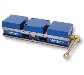
Universal Machining Chucks. 4-Jaw Vertical
 Universal Machining Chucks 4-Jaw Vertical Parts are gripped firmly by the formed jaws, ensuring high precision (deviation within 0.03mm) Large workpieces can be held tight with the low profile vise body
AL-960B - Centre Lathe 305 x 925mm Turning Capacity Includes Cabinet Stand
 AL-960B - Centre Lathe 305 x 925mm Turning Capacity Includes Cabinet Stand Ex GST Inc GST $4,690.00 $5,159.00 ORDER CODE: MODEL: Swing Over Bed (mm): Distance Between Centres (mm): Spindle Bore (mm): Swing
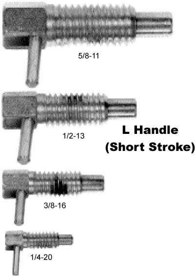
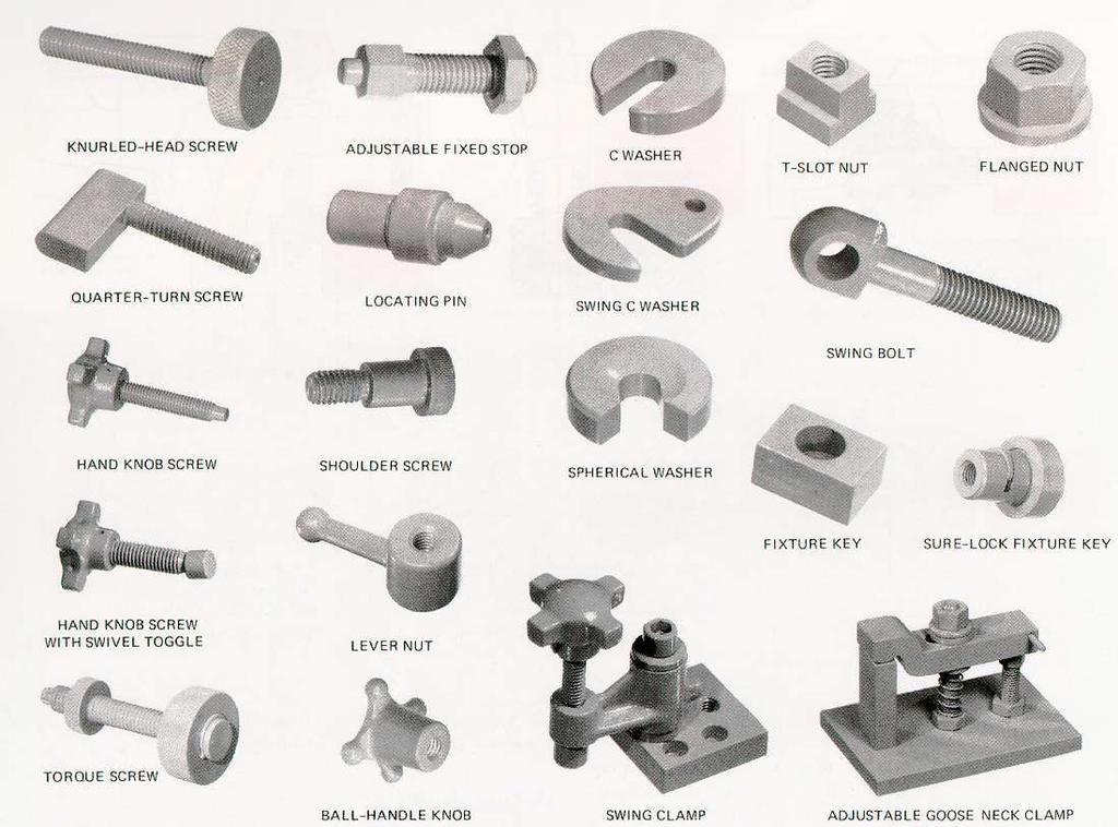
Screws. Introduction. 1. Nuts, bolts and screws used to clamp things together. Screws are used for two purposes:
 Screws Introduction Screws are used for two purposes: 1. To clamp things together. 2. To control motion. 1. Nuts, bolts and screws used to clamp things together. Nuts, bolts and screws that are used for
The jigs and fixtures are the economical ways to produce a component in mass production system. These are special work holding and tool guiding device
 The jigs and fixtures are the economical ways to produce a component in mass production system. These are special work holding and tool guiding device Quality of the performance of a process largely influenced
PREVIEW COPY. Table of Contents. Using the Horizontal Milling Machine...3. Lesson Two Slab Milling Procedures...19
 Table of Contents Lesson One Using the Horizontal Milling Machine...3 Lesson Two Slab Milling Procedures...19 Lesson Three Milling Slots and Angles...35 Lesson Four Straddle, Side, and Face Milling...51
AL-960B - Centre Lathe 305 x 925mm Turning Capacity Includes Digital Readout & Cabinet Stand
 AL-960B - Centre Lathe 305 x 925mm Turning Capacity Includes Digital Readout & Cabinet Stand Ex GST Inc GST $5,690.00 $6,259.00 ORDER CODE: MODEL: Swing Over Bed (mm): Distance Between Centres (mm): Spindle
PESIT-BANGALORE SOUTH CAMPUS Hosur Road 1 KM before Electronic City, Bangalore DEPARTMENT OF MECHANICAL ENGINEERING MACHINE SHOP 15MEL48B
 PESIT-BANGALORE SOUTH CAMPUS Hosur Road 1 KM before Electronic City, Bangalore-560100 DEPARTMENT OF MECHANICAL ENGINEERING IV SEMESTER B.E MACHINE SHOP 15MEL48B ACADEMIC YEAR 2016 2017 LABORATORY MANUAL
no mm no Dividers with scriber 150 mm NEW Square wedge-shaped knife edges on the length side
 Summer Promotion valid until 30.06.2013 all quoted prices are incl. VAT for deliveries to EU countries to customers with valid VAT-no. and for deliveries in non EU member countries the VAT is not applicable
أت ارش. Dr. Abdel-Wahab El-Morsy Faculty of Engineering - Rabigh
 Basic Workshop 1 أت ارش Machining Process Machining is a term used to describe a variety of material removal processes in which a cutting tool removes unwanted material from a workpiece to produce the
STEEL RULE. Stock TRY SQUARE
 FITTING INTRODUCTION Fitting consists of a handwork involved in fitting together components usually performed at a bench equipped with a vice and hand tools. The matting components have a close relation
VARIABLE SPEED WOOD LATHE. Model DB900 INSTRUCTION MANUAL
 VARIABLE SPEED WOOD LATHE Model DB900 INSTRUCTION MANUAL 1007 TABLE OF CONTENTS SECTION...PAGE Technical data.. 1 General safety rules....1-3 Specific safety rules for wood lathe.....3 Electrical information.4
PREVIEW COPY. Table of Contents. Lathes and Attachments...3. Basic Lathe Operations Lesson Five Threads and Threading...73
 Table of Contents Lesson One Lesson Two Lesson Three Lesson Four Lathes and Attachments...3 Basic Lathe Operations...21 Drilling and Boring...39 Reaming...57 Lesson Five Threads and Threading...73 Copyright
TU-2004V - Opti-Turn Bench Lathe 200 x 300mm Turning Capacity Electronic Variable Speeds
 TU-2004V - Opti-Turn Bench Lathe 200 x 300mm Turning Capacity Electronic Variable Speeds Ex GST Inc GST $1,150.00 $1,265.00 ORDER CODE: MODEL: Swing Over Bed (mm): Distance Between Centres (mm): Spindle
STATE UNIVERSITY OF NEW YORK SCHOOL OF TECHNOLOGY CANTON, NEW YORK
 STATE UNIVERSITY OF NEW YORK SCHOOL OF TECHNOLOGY CANTON, NEW YORK COURSE OUTLINE MECH 121 - MANUFACTURING PROCESSES I Prepared By: Daniel Miller Updated By: Daniel Miller (April 2015) CANINO SCHOOL OF
 VALLIAMMAI ENGINEERING COLLEGE DEPARTMENT OF MECHANICAL ENGINEERING QUESTION BANK ME6402 MANUFACTURING TECHNOLOGY II UNIT-I PART A 1. List the various metal removal processes? (BT1) 2. Explain how chip
OD1644 MILLING MACHINE OPERATIONS
 SUBCOURSE OD1644 MILLING MACHINE OPERATIONS EDITION 8 US ARMY WARRANT OFFICER ADVANCED COURSE MOS/SKILL LEVEL: 441A MILLING MACHINE OPERATIONS SUBCOURSE NO. OD1644 EDITION 8 US Army Correspondence Course