Milling Machine Operations
|
|
|
- Lucas McCormick
- 6 years ago
- Views:
Transcription
1 03/05/2004
2 TABLE OF CONTENTS Lesson 1 Objectives Vertical Mill 4 Milling Machine Accessories Common Milling Cutters Metal Saws 24 End Mills 25 T-Slot Cutter 25 Dovetail Cutter Woodruff Keyseat Cutter Flycutters 26 Cutting Speeds and Feeds Calculating Speeds and Feeds Milling Machine Safety Lesson 2 Objectives Milling Machine Set-Up Alignment Techniques Common Mill Operations Alignment of the Head Machining a Flat Surface Squaring Work on a Milling Machine Machining the Ends Square Machining an Angular Surface Cutting Slots and Keyways Woodfuff Keys 40
3 Page 3 of 37 COURSE TERMINAL OBJECTIVE Given a job assignment requiring the use of a milling machine, the Maintenance Mechanic will describe the components of the milling machine and the various operations that can be performed. Mastery will be demonstrated by the completion of a comprehensive written examination with a minimum score of 80% complete. LESSON ONE TERMINAL OBJECTIVE Given a job assignment requiring the use of a milling machine, the Maintenance Mechanic will describe the components and accessories of a milling machine. LESSON ONE ENABLING OBJECTIVES EO1- Describe the components of a vertical milling machine EO2- Identify and state the purpose of the common milling machine accessories. EO3- Identify and state the purpose of the common milling cutters. EO4- State the methods for determining the proper cutting speeds, feeds, and depth of cut for various materials and cutters. EO5- State the safety precautions when working on a milling machine.

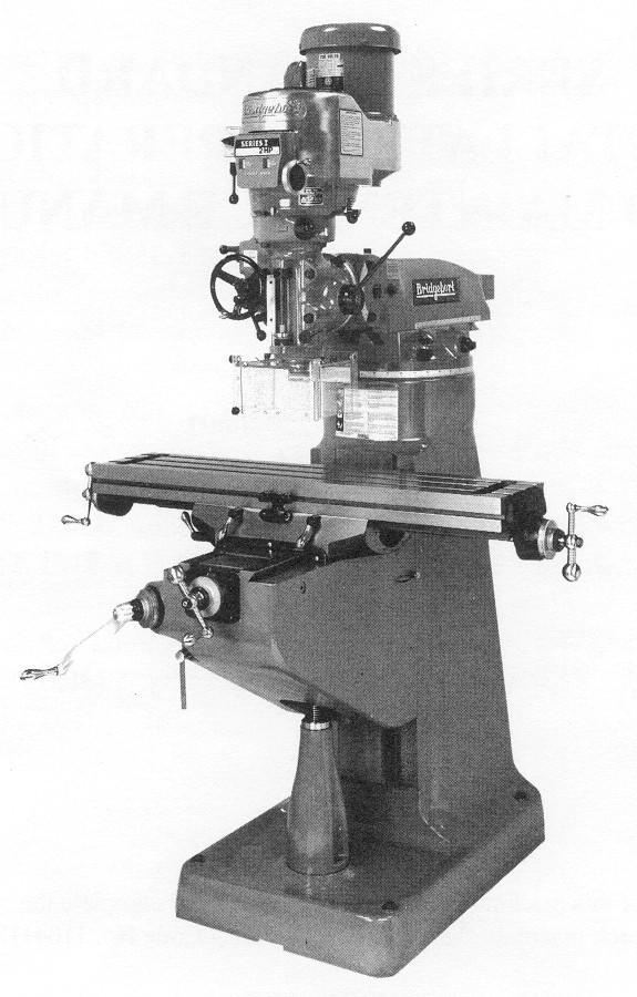
4 Page 4 of 37 The standard vertical milling machine has the cutter spindle mounted in a vertical position. The head on most vertical milling machines may be swiveled, which readily permits the machining of angular surfaces. The cutters used are of the end mill or shell end mill types. This type of machine is particularly suited to the use of the rotary table, permitting the machining of circular grooves and positioning of holes that have been laid out with angular measurements. EO01- DESCRIBE THE COMPONENTS OF A VERTICAL MILLING MACHINE PARTS OF THE RAM-TYPE VERTICAL MILL The base is made of ribbed cast iron. It may contain a coolant reservoir. The column is often cast integrally with the base. The machined face of the column provides the ways for vertical movement of the knee. The upper part of the column is machined to receive a turret on which the overarm is mounted. The overarm is round, or of the ram type. It may be adjusted toward or away from the column to increase the capacity of the machine. The head is attached to the end of the ram. Provision is made to swivel the head in one plane. On universal-type machines, the head may be swiveled in two planes. Mounted on top of the head is the motor which provides the drive to the spindle. The spindle may be fed by means of a hand lever, a handwheel, or automatic power feed. Most machines are equipped with a micrometer quill stop for precision drilling or boring to depth. The knee moves up and down on the face of the column and supports the saddle and the table. Vertical milling machines are normally equipped with plain tables only.
5 Page 5 of 37 The turret pivots the entire upper assembly for special setups or to use the slotting attachment (accessory). The following pages describe, in detail, the head controls for the Bridgeport Mills.
6 Page 6 of 37
7 Page 7 of 37
8 Page 8 of 37
9 Page 9 of 37
10 Page 10 of 37
11 Page 11 of 37
12 Page 12 of 37
13 Page 13 of 37
14 Page 14 of 37
15 Page 15 of 37
16 Page 16 of 37
17 Page 17 of 37
18 Page 18 of 37
19 Page 19 of 37
20 Page 20 of 37
21 Page 21 of 37
22 Page 22 of 37

23 Page 23 of 37 EO2- IDENTIFY AND STATE THE PURPOSE OF THE COMMON MILLING MACHINE ACCESSORIES. MILLING MACHINE ACCESSORIES A wide variety of accessories, which greatly increase its versatility and productivity, are available for the milling machine. These accessories may be classified as fixtures or attachments. Fixtures. A fixture is a work holding device fastened to the table of a machine or to a machine accessory, such as a rotary table. It is designed to hold workpieces that cannot readily be held in a vise or in production work when large quantities are to be machined. The fixture is generally custom designed so that the identical parts will be positioned exactly and held securely. Attachments. Milling machine attachments may be divided into three classes: 1. Those designed to hold special attachments; these are attached to the spindle and column of the machine. 2. Arbors, collets and adapters which are designed to hold standard cutters. These are mounted in the spindle. 3. Those designed to hold the workpiece, such as a vise, rotary table, and indexing or dividing head. Milling machine vises are the most widely used work-holding devices for milling; they are available in three styles: The plain vise may be bolted to the table so that its jaws are parallel or at right angles to the X axis. The vise is positioned quickly and accurately by keys on the bottom which fit into T-slots on the table.


24 Page 24 of 37 The swivel base vise is similar to the plain vise, except that it has a swivel base that enables the vise to be swiveled through 360O in a horizontal plane. The universal vise may be swiveled through 360O in a horizontal plane and may be tilted from 0 to 90O in a vertical plane. It is used primarily by toolmakers, moldmakers, and diemakers, since it permits the setting of compound angles for milling. Vises are a piece of precision equipment. Don't abuse them. They are not anvils or to be used for bending metal. EO3- IDENTIFY AND STATE THE PURPOSE OF THE COMMON MILLING CUTTERS METAL SAWS Metal-slitting saws are basically thin plain milling cutters with sides relieved or "dished" to prevent rubbing or binding. Slitting saws are made in width from 1/32-3/16 in. Because of their thin cross section, they should be operated at approximately one-quarter to oneeighth of the feed per tooth used for other cutters. The arbor nut should be pulled up as tightly as possible by hand only. Do not use any cheaters, use the wrench only.


25 Page 25 of 37 END MILLS End mills have cutting teeth on the end as well as on the periphery and are fitted to the spindle by a suitable adapter. They are of two types, the solid end mill in which the shank and cutter are one piece, and the shell end mill, which uses a separate shank. Solid end mills, generally smaller than shell end mills, may have either straight or helical flutes. They are available with straight and tapered shanks and with two or more flutes. When a slot is cut with a two-flute end mill, the depth of cut should not exceed one-half the diameter of the cutter. When the four-flute end mill is used for slot cutting, it is started at the edge of the metal. T-SLOT CUTTER The T-slot cutter (Fig. 17-A) is used to cut the wide horizontal groove at the bottom of a T-slot after the narrow vertical groove has been machined with an end mill. It consists of a small side milling cutter with teeth on both sides and a shank for mounting. DOVETAIL CUTTER The dovetail cutter (Fig. 17-B) is similar to a singleangle milling cutter with an integral shank. Dovetail cutters are available with an internal thread to be mounted on a special shank. They are used to form the sides of a dovetail after the tongue or groove has been machined with a side milling cutter. Dovetail cutters are available with 45, 50, 55, or 60O angles. WOODRUFF KEYSEAT CUTTER The Woodruff keyseat cutter is similar to a plain and side milling cutter. Smaller sizes are made with a solid shank and straight teeth; larger sizes are mounted on an arbor and have staggered teeth. They are used for milling semicylindrical keyseat in shafts.

26 Page 26 of 37 FLYCUTTERS The flycutter is a single-pointed cutting tool with the cutting end ground to the desired shape. It is mounted in a special adapter or arbor. Since all the cutting is done with one tool, a fine feed must be used. They are used in experimental work where the high cost of a special cutter would not be warranted. EO4- STATE THE METHODS FOR DETERMINING THE PROPER CUTTING SPEEDS, FEEDS, AND DEPTH OF CUT FOR VARIOUS MATERIALS AND CUTTERS CALCULATING CUTTING SPEEDS AND MILLING FEEDS Speed. One of the most important factors affecting the efficiency of a milling operation is cutter speed. The cutting speed of a metal may be defined as the speed, in surface feet per minute (sfm) at which the metal may be machined efficiently. We will refer to surface feet per minute as cutting speed. When work is machined on a lathe, it must be turned at a specific number of revolutions per minute (rpm), depending on its diameter, to achieve the proper cutting speed. When work is machined in a milling machine, the cutter must be revolved at a specified rpm, depending on its diameter, to achieve the proper cutting speed. Since different types of metals vary in hardness, structure, and machinability, different cutting speeds must be used for each type of metal and for various cutter materials. Several factors must be considered when determining the proper rpm at which to machine a metal: The type of work material The cutter material The diameter of the cutter The surface finish required The depth of cut being taken The rigidity of the machine and work setup

27 Page 27 of 37 To get optimum use for a cutter, the proper speed at which the cutter should be revolved must be determined. When machining mild steel, a high speed cutter would have to achieve a surface speed of about 90 ft/min. Since the diameter of the cutter affects this speed, it is necessary to consider the diameter in the calculation. The following example illustrates how the formula is developed. EXAMPLE Calculate the speed required to revolve a 3-inch diameter high-speed steel milling cutter when cutting machine steel. 1. First, determine the circumference of the cutter. Circumference of Cutter = 3 inches x To determine the proper cutter speed or RPM, it is necessary only to divide the cutting speed (CS) by the circumference of the cutter: RPM = = CS (ft) circumference (in.) 90 3 x Since the numerator is in feet and the denominator in inches, the numerator must be changed to inches and the formula simplified: RPM = 4 x CS D Although these formulas are helpful in calculating the cutter (spindle) speed, it should be remembered that they are approximate only, and the speed may have to be altered because of the metal and/or the machine condition. Best results may be obtained if the following rules are observed: For longer cutter life, use the lower CS in the recommended range.
28 Page 28 of 37 Know the hardness of the material to be machined. When starting a new job, use the lower range of the CS and gradually increase to the higher range if conditions permit. If a fine finish is required, reduce the feed rather than increase the cutter speed. The use of coolant, properly applied will generally produce a better finish and lengthen the life of the cutter because it absorbs heat, acts as a lubricant, and washes chips away. Feed. Milling machine feed may be defined as the distance in inches per minute that the work moves into the cutter. On most milling machines, the feed is regulated in inches per minute (IPM) and is independent of the spindle speed. This arrangement permits faster feeds for larger, slowly rotating cutters. The milling feed is determined by multiplying the chip size (chip per tooth) desired, the number of teeth in the cutter and the rpm of the cutter. Chip per tooth (CPT) is the amount of material which should be removed by each tooth of the cutter as it revolves and advances into the workpiece. The feed rate used on a milling machine depends on a variety of factors: The depth and width of cut The design or type of cutter The sharpness of the cutter The workpiece material The strength and uniformity of the workpiece The type of finish and accuracy required The power and rigidity of the machine As the work advances into the cutter, each successive tooth advances into the work an equal amount, producing chips of equal thickness. It is this thickness of the chips or the feed per tooth, along with the number of teeth in the cutter, which form the basis for determining the rate of feed. The ideal feed rate may be determined as follows: Feed = number of teeth x feed/tooth x cutter rpm The formula used to find the work feed in inches per minute is: IPM = N x CPT x RPM N = number of teeth in the cutter CPT = chips per tooth for a particular cutter and metal RPM = revolutions per minute of the spindle
 = N x CPT x RPM = 12 x 0.010 x 91 = 10.")
29 Page 29 of 37 EXAMPLE Find the feed in inches per minute using a 3.5-inch diameter 12-tooth helical cutter to cut machine steel (CS 80). It would first be necessary to calculate the proper rpm for the cutter: 4 x CS 4 x 80 RPM = D = 3.5 = 91 Feed (IPM) = N x CPT x RPM = 12 x x 91 = 10.9 or 11 The calculated feeds would be possible only under ideal conditions, it is suggested that the milling machine feed be set to approximately one-third or one-half the amount calculated. The feed can then be gradually increased to the capacity of the machine and the finish desired. Depth of cut. Where smooth accurate finish is desired, it is considered good milling practice to take a rough and finishing cut. Roughing cuts should be deep, with a feed as heavy as the work and the machine will allow. Heavier cuts may be taken with helical cutters having fewer teeth since they are stronger and have a greater chip clearance than cutters with more teeth. Finishing cuts should be light, with a finer feed than is used for roughing cuts. The depth of the cut should be at least 1/64 inch. Lighter cuts and extremely fine feeds are not advisable since the chip taken by each tooth will be thin and the cutter will rub on the surface of the work, rather than bite into it, dulling the cutter. When a fine finish is required, the feed should be reduced rather than speeding the cutter up. More cutters are dulled by high speeds than by high feeds. To prevent damage to the finished surface, never stop the feed when the cutter is revolving over the workpiece. For the same reason, move the cutter before returning the work to the starting position upon completion of the cut.
30 Page 30 of 37 EO5- STATE THE SAFETY PRECAUTIONS WHEN WORKING ON A MILLING MACHINE MILLING MACHINE SAFETY The milling machine, like any other machine, demands the total attention of the operator and a thorough understanding of the hazards associated with its operation. The following points should be observed when operating the milling machine: Be sure that the work and cutter are mounted securely before taking a cut. Always wear safety glasses. When mounting or removing milling cutters, always hold them with a cloth to avoid the sharp edges. When setting up work, move the table as far as possible from the cutter to avoid any injury. Be sure that the cutter and machine parts will clear the work before making any cut. Never attempt to mount, measure, or adjust work until the cutter is completely stopped. Do not attempt to stop the cutter with your hand. Keep hands, brushes, and rags away from a revolving milling cutter at all times. When using milling cutters, do not use an excessively heavy cut or feed. This can cause the cutter to break and the resulting flying pieces may cause injury. Always use a brush, never a rag, to remove the cuttings after the cutter has stopped revolving. Never reach over or near or around a revolving cutter; keep hands at least 12 inches from the revolving cutter.
31 Page 31 of 37 Keep the floor around the machine free of chips, oil, and cutting fluid.
32 Page 32 of 37 LESSON TWO TERMINAL OBJECTIVE Given a job assignment that requires the performance of milling machine operations, the Maintenance Mechanic will describe the proper set-up and performance of the various milling machine operations. ENABLING OBJECTIVES EO1- Describe the proper set-up of a milling machine for various milling machine operations. EO2- Describe the more common milling operations performed on a vertical milling machine.


33 Page 33 of 37 EO1- DESCRIBE THE PROPER SET-UP OF A MILLING MACHINE FOR VARIOUS MILLING OPERATIONS ALIGNMENT TECHNIQUES When a workpiece is mounted in a milling machine vise, the vise must be properly aligned. Generally, the stationary jaw of the vise must be either at right angles to the face of the machine column, or it must be parallel with the face of the column. Right angle squareness of the vise with the column can be checked by placing the blade of a precision steel square against the stationary jaw of the vise while placing the beam of the square against the machined surface of the column. Another method to check alignment is to place parallel bars between the machine column and the angle plate. No light should show between the parallel and the column. This is done for rough alignment. Final Alignment is to be done with dial indicator. Parallelism of the stationary jaw can be checked with a dial indicator (within.001tir). Clamp the indicator to the spindle with the plunger touching the stationary vise jaw. Correct any misalignment.


34 Page 34 of 37 EO2- DESCRIBE THE MORE COMMON MILLING MACHINE OPERATIONS ON A VERTICAL MILLING MACHINE VERTICAL MILLING MACHINE OPERATIONS The vertical milling machine offers a great deal of versatility. The vertical milling machine can be used for machining flat surfaces, angular surfaces, drilling, boring, and machining keyways and circular grooves. ALIGNMENT OF THE VERTICAL HEAD Proper alignment of the head is important when machining holes, pockets or when face milling. If the head is not at an angle of 90O to the table, the holes will not be square with the work surface when the cutting tool is fed. When face milling, the machined surface will be stepped if the head is not square with the table. Although all heads are graduated in degrees and some have vernier devices for setting the head, it is a good idea to check the spindle alignment. 1. Mount a dial indicator on the spindle at 90O, on a suitable rod. 2. Position the indicator over the top of the table. 3. Carefully lower the spindle until the indicator button touches the table and the dial indicator registers about a half of a revolution. Set the indicator to zero and lock the spindle in place. 4. Carefully rotate the vertical mill spindle 180O by hand until the button bears on the opposite side of the table. Compare the two readings. (Should be less than.001tir) 5. If there is any discrepancy in the readings, loosen the locking nuts on the swivel mounting and adjust the head until the indicator registers one-half the difference between the two readings. Tighten the locking nuts. 6. Recheck the accuracy of the head and adjust if necessary. 7. Rotate the vertical mill spindle 90O, and set the dial indicator again. 8. Rotate the spindle 180O and compare the two readings. Adjust as necessary. 9. Tighten the locking nuts on the swivel head. 10. Recheck the readings and adjust as necessary.
35 Page 35 of 37 NOTE: When readings are taken, it is important that the indicator button does not catch in the Tslots on the table. To prevent this, it is advisable to work from the high reading first and then rotate to the low reading. The longer the rod used on the dial indicator, the more accurate the setting will be. MACHINING A FLAT SURFACE 1. Clean the vise and mount the work securely in the vise, on parallels if necessary. 2. Check that the vertical head is square with the table. 3. If possible, select a cutter, which will just overlap the edges of the work. It will then require only one cut to machine the surface. If the surface to be machined is narrow, an end mill slightly larger in diameter that the width of the work should be used. If the surface is large and requires several passes, a shell end mill or suitable fly cutter should be used. 4. Set the proper spindle speed for the size and type of cutter and material being machined. 5. Tighten the quill clamps. 6. Start the machine, and adjust the table until the end of the work is under the edge of the cutter. 7. Raise the table until the work surface just touches the cutter. Move the work clear of the cutter. 8. Raise the table about 1/32 inch and take a trail cut for approximately 1/4 inch. 9. Move the work clear of the cutter, stop the cutter, and measure the work. 10. Raise the table the desired amount, and lock the knee clamp. 11. Mill the surface to size using the automatic feed (or hand feed if desired). SQUARING WORK ON A MILLING MACHINE In order to mill the four sides of a piece of work so that they are square and parallel, it is important that each side be milled in a definite order. It is very important that dirt and burrs be removed from the work and vise since they can cause inaccurate work.
36 Page 36 of 37 Machining Side 1 1. Clean the vise thoroughly and remove all burrs from the workpiece. 2. Set the work in the vise with the first surface (Side 1) facing up. 3. Insert a soft metal rod between the work and the movable jaw if that portion of the work is rough or not square. 4. Tighten the vise securely. 5. With a soft-faced hammer, tap the workpiece down in the vise until it sits securely. 6. Mount a suitable cutter in the milling machine spindle. 7. Set the machine for the proper speed for the size of cutter and the material to be machined. 8. Start the machine and raise the table until the cutter just touches the right-hand end of side 1.
37 Page 37 of Move the work clear of the cutter. 10. Raise the table about.030 in. and machine side 1 using a steady feed rate. 11. Take the work out of the vise and remove all burrs from the edges with a file. Machining Side Clean the vise and work thoroughly. 13. Place the work on the vise with Side 1 against the solid jaw of the vise and Side 2 up. 14. Place a round bar between Side 4 and the movable jaw, if necessary. 15. Secure the workpiece in the vise by tapping with a soft-faced hammer. 16. Machine Side Remove the workpiece from the vise and file the burrs from the edges. Machining Side Clean the vise and work. 19. Place Side 2 facing down with Side 1 remaining against the solid jaw of the vise. 20. Place the round bar between side 4 and the movable jaw. 21. Tighten the vise securely and tap the workpiece down. 22. Start the machine and raise the table until the cutter just touches the right-hand end of Side Move the work clear of the cutter and raise the table about.010 in. 24. Take a trial cut, stop the machine, and measure the width of the work. 25. Raise the table the required amount and machine Side 3 to the correct width. 26. Remove the work and file off all burrs. Machining Side Clean the vise and work. 28. Place Side 1 down on the vise with Side 4 up. 29. Tighten the vise. 30. Machine Side 4 to the correct size.

38 Page 38 of 37 MACHINING THE ENDS SQUARE Two common methods are used to square the ends of the workpieces in a vertical mill. Short pieces are generally held vertically in the vise and are machined with an end mill or flycutter. Long pieces are generally held flat in the vise with one end extending past the end of the vise. The end surface is then cut square with an end mill. Short Work Squaring 1. Set the work in the center of the vise with one of the end up and tighten the vise. 2. Hold a square down firmly on the top and bring the blade into contact with the side of the work. 3. Tap the work until its edge is aligned with the blade of the square. 4. Tighten the vise securely and recheck the squareness. 5. Take about in. cut and machine the end square. 6. Remove the burrs from the end of the machined surface. 7. Clean the vise and set the machined end on paper feelers in the bottom of the vise. 8. Tighten the vise securely and tap the work down until the paper feelers are tight. 9. Take a trial cut from the end to clean up the surface. 10. Measure the length of the workpiece with a depth micrometer. 11. Raise the table the required amount and machine the work to length. MACHINING AN ANGULAR SURFACE 1. Layout and mark the angular surface. 2. Clean the vise. 3. Align the vise with the direction of feed. 4. Mount the work on parallels in the vise. 5. Swivel the vertical head to the required angle. 6. Tighten the quill clamp. 7. Start the machine and raise the table until the cutter touches the work. Carefully raise the table to set the desired depth of cut. 8. Take a trial cut for about 1/2 inch. 9. Check the angle with a protractor 10. If the angle is correct, continue the cut.

39 Page 39 of Machine to the required depth, taking several cuts if necessary Alternate Method Angles may sometimes be cut by leaving the head in a vertical position and setting the work on an angle in the vise. This will depend on the shape and size of the workpiece. Sometimes, a universal vise can be set to the required angle. CUTTING SLOTS AND KEYWAYS Slots and keyseats with one or two blind ends may be cut in shafts more easily on a vertical milling machine, using a two- or three-fluted end mill. 1. Lay out the position of the keyseat on the shaft and scribe reference lines on the end of the shaft. 2. Secure the workpiece in a vise on a parallel. If the shaft is long, it may be clamped directly to the table by placing it in one of the table slots, or on V-blocks 3. Using the layout lines on the end of the shaft, set up the shaft so that the keyseat layout is in the proper position on the top of the shaft. 4. Mount a two- or three-fluted end mill of a diameter equal to the width of the keyway, in the milling machine spindle. NOTE: If the keyseat has two blind ends, a two- or three-lip end mill must be used since they will act as a drill to start the slot. If the slot is at an end of the shaft (one blind end), a four-fluted end mill may be used, but a two- or three-lip end mill would give better chip clearance. 5. Center the workpiece by carefully touching the cutter to one side of the shaft. A thin piece of paper can be used to protect the finish of the shaft. 6. Lower the table until the cutter clears the workpiece. 7. Move the table over an amount equal to half the diameter of the shaft plus half the diameter of the cutter (plus the thickness of paper if used). NOTE: Alternate methods include the use of an edge finder or a dial test (trammel) indicator. 8. If the keyseat being cut has two blind ends, adjust the work until the end of the keyseat is aligned with the edge of the cutter. 9. Feed the cutter down (or the table up) until the cutter just cuts to its full diameter. If the keyseat has only one blind end, the work is adjusted so that this cut is taken at the end of the work. The work is then moved clear of the cutter. 10. Set the depth of cut to one-half the thickness of the key and machine the keyseat to the proper length.

40 Page 40 of 37 WOODRUFF KEYS Woodruff Keys are used when keying shafts and mating parts. Woodruff keyseats are more quickly cut than are square keyseats, and the key should not require any fitting after the keyseat has been cut. Woodruff keys are semicircular in shape and can be purchased in standard sizes (designated by E numbers). They can also be made from round bar stock of the required diameter. Woodruff Keyseat cutters have shank diameters of 1/2 in. for cutters up to 11/2 inches in diameter. The shank is undercut adjacent to the cutter to permit the cutter to into the proper depth. The sides of the cutter are slightly tapered toward the center to permit clearance while cutting. Cutters over 2 in. are mounted on an arbor. The size of the cutter is stamped on the shank. The last two digits indicate the nominal diameter in eighths of an inch. The digit or digits preceding the last two numbers indicate the nominal width of the cutter in thirty-seconds of an inch. Thus, a cutter marked 608 would be 8 x 1/8 or 1 inch in diameter, and 6 x 1/32, or 3/16 in. wide. The key would be a semicircular cross section to fit the groove exactly. Cutting a Woodruff Keyseat. 1. Align the spindle of the vertical milling machine to 90O. 2. Lay out the position of the keyseat. 3. Set the shaft in the vise of the milling machine or on V-blocks. Be sure that the shaft is level and parallel to the table. 4. Mount a cutter of the proper size in the spindle. 5. Start the cutter and touch the bottom of the cutter to the top of the workpiece. Set the vertical graduated feed collar to zero. 6. Move the work clear of the cutter. Raise the table half of the diameter of the work plus half the thickness of the cutter. Lock the knee at this position. 7. Position the center of the slot with the center of the cutter. Lock the table in this position. 8. Touch the revolving cutter to the work. Set the crossfeed collar to zero. 9. Cut the keyseat to the proper depth.
PALO VERDE NUCLEAR GENERATING STATION
 PALO VERDE NUCLEAR GENERATING STATION Mechanical Maintenance Training Milling Machine Components Classroom Lesson Mechanical Maintenance Training Date: 12/3/2010 5:08:31 PM LP Number: Rev Author: MARK
PREVIEW COPY. Table of Contents. Using the Horizontal Milling Machine...3. Lesson Two Slab Milling Procedures...19
 Table of Contents Lesson One Using the Horizontal Milling Machine...3 Lesson Two Slab Milling Procedures...19 Lesson Three Milling Slots and Angles...35 Lesson Four Straddle, Side, and Face Milling...51
Lathe. A Lathe. Photo by Curt Newton
 Lathe Photo by Curt Newton A Lathe Labeled Photograph Description Choosing a Cutting Tool Installing a Cutting Tool Positioning the Tool Feed, Speed, and Depth of Cut Turning Facing Parting Drilling Boring
Typical Parts Made with These Processes
 Turning Typical Parts Made with These Processes Machine Components Engine Blocks and Heads Parts with Complex Shapes Parts with Close Tolerances Externally and Internally Threaded Parts Products and Parts
HOW TO USE MILLING MACHINE?
 HOW TO USE MILLING MACHINE? Milling is the process of machining flat, curved, or irregular surfaces by feeding the workpiece against a rotating cutter containing a number of cutting edges. The usual Mill
OD1644 MILLING MACHINE OPERATIONS
 SUBCOURSE OD1644 MILLING MACHINE OPERATIONS EDITION 8 US ARMY WARRANT OFFICER ADVANCED COURSE MOS/SKILL LEVEL: 441A MILLING MACHINE OPERATIONS SUBCOURSE NO. OD1644 EDITION 8 US Army Correspondence Course
PREVIEW COPY. Table of Contents. Lesson Two Shaping and Planing Lesson Three Grinding Operations Lesson Four Gear Cutting...
 Table of Contents Lesson One Milling Operations...3 Lesson Two Shaping and Planing...19 Lesson Three Grinding Operations...37 Lesson Four Gear Cutting...55 Lesson Five Power Sawing...73 Copyright 1975,
Summer Junior Fellowship Experience at LUMS. Maliha Manzoor 13 June 15 July, 2011 LUMS Summer Internship
 Summer Junior Fellowship Experience at LUMS Maliha Manzoor 13 June 15 July, 2011 LUMS Summer Internship Internship Schedule June 13-17: 2D and 3D drawings in AutoCAD June 20-24: 2D and 3D drawings in AutoCAD
Vertical Milling Machine Operations
 Vertical Milling Machine Operations UNIT 3 Learning Objectives After completing this unit, the student should be able to: Describe vertical milling machine safety practices Describe the purpose and process
COLLEGE OF ENGINEERING MACHINE SHOP FACILITIES AND PRACTICES Prepared by Mike Allen July 31, 2003 Edited by Scott Morton February 18, 2004
 1 COLLEGE OF ENGINEERING MACHINE SHOP FACILITIES AND PRACTICES Prepared by Mike Allen July 31, 2003 Edited by Scott Morton February 18, 2004 I. OBJECTIVE To provide an overview and basic knowledge of the
MANUFACTURING TECHNOLOGY
 MANUFACTURING TECHNOLOGY UNIT V Machine Tools Milling cutters Classification of milling cutters according to their design HSS cutters: Many cutters like end mills, slitting cutters, slab cutters, angular
Milling. Chapter 24. Veljko Samardzic. ME-215 Engineering Materials and Processes
 Milling Chapter 24 24.1 Introduction Milling is the basic process of progressive chip removal to produce a surface. Mill cutters have single or multiple teeth that rotate about an axis, removing material.
Ahsanullah University of Science and Technology (AUST) Department of Mechanical and Production Engineering
 Department of Mechanical and Production Engineering") Ahsanullah University of Science and Technology (AUST) Department of Mechanical and Production Engineering LABORATORY MANUAL For the students of Department of Mechanical and Production Engineering 1 st
Ahsanullah University of Science and Technology (AUST) Department of Mechanical and Production Engineering LABORATORY MANUAL For the students of Department of Mechanical and Production Engineering 1 st
Chapter 22 MACHINING OPERATIONS AND MACHINE TOOLS
 Chapter 22 MACHINING OPERATIONS AND MACHINE TOOLS Turning and Related Operations Drilling and Related Operations Milling Machining Centers and Turning Centers Other Machining Operations High Speed Machining
Chapter 24 Machining Processes Used to Produce Various Shapes.
 Chapter 24 Machining Processes Used to Produce Various Shapes. 24.1 Introduction In addition to parts with various external or internal round profiles, machining operations can produce many other parts
Lathes. CADD SPHERE Place for innovation Introduction
 Lathes Introduction Lathe is one of the most versatile and widely used machine tools all over the world. It is commonly known as the mother of all other machine tool. The main function of a lathe is to
Lathe Accessories. Work-holding, -supporting, and driving devices
 46-1 Lathe Accessories Divided into two categories Work-holding, -supporting, and driving devices Lathe centers, chucks, faceplates Mandrels, steady and follower rests Lathe dogs, drive plates Cutting-tool-holding
Turning and Lathe Basics
 Training Objectives After watching the video and reviewing this printed material, the viewer will gain knowledge and understanding of lathe principles and be able to identify the basic tools and techniques
Machining. Module 6: Lathe Setup and Operations. (Part 2) Curriculum Development Unit PREPARED BY. August 2013
 Curriculum Development Unit PREPARED BY. August 2013") Machining Module 6: Lathe Setup and Operations (Part 2) PREPARED BY Curriculum Development Unit August 2013 Applied Technology High Schools, 2013 Module 6: Lathe Setup and Operations (Part 2) Module Objectives
Machining Module 6: Lathe Setup and Operations (Part 2) PREPARED BY Curriculum Development Unit August 2013 Applied Technology High Schools, 2013 Module 6: Lathe Setup and Operations (Part 2) Module Objectives
Introduction to Machining: Lathe Operation
 Introduction to Machining: Lathe Operation Lathe Operation Lathe The purpose of a lathe is to rotate a part against a tool whose position it controls. It is useful for fabricating parts and/or features
STEEL RULE. Stock TRY SQUARE
 FITTING INTRODUCTION Fitting consists of a handwork involved in fitting together components usually performed at a bench equipped with a vice and hand tools. The matting components have a close relation
Grizzly Drill Press SOP
 Grizzly Drill Press SOP Drill Press is wired to run on 0V. Drill Press has a built in light with a ON/OFF switch. Never hold a workpiece by hand while drilling. Clamp it down or hold it in a vice. Never
Machine Tools MILLING PROCESS. BY LAKSHMIPATHI YERRA Asst.professor Dept.of Mechanical Engg.
 Machine Tools MILLING PROCESS BY LAKSHMIPATHI YERRA Asst.professor Dept.of Mechanical Engg. FIG. 1 Typical parts and shapes produced by various cutting processes Fig. 2 Schematic illustration of milling
Metal Cutting - 5. Content. Milling Characteristics. Parts made by milling Example of Part Produced on a CNC Milling Machine 7.
 Content Metal Cutting - 5 Assoc Prof Zainal Abidin Ahmad Dept. of Manufacturing & Industrial Engineering Faculty of Mechanical Engineering Universiti Teknologi Malaysia 7. MILLING Introduction Horizontal
TOP WORK ISO 9001.CE UNIVERSAL CUTTER & TOOL GRINDER
 TOP WORK ISO 9001.CE UNIVERSAL CUTTER Precise ball groove of conformation Inclination of Wheelhead The wheelhead can easily tilt up to ±15 degrees, with a 360-degrees swivel on the horizontal plane. The
WF WF Tool Milling Machines. Milling Machines for Die Making with digital position indicator.
 Tool Milling Machines Milling Machines for Die Making with digital position indicator automatic feeds on all 3 axes vertical head quill for drilling quill stroke 3" versatile for many applications for
Instruction Sheet MCHE 365 & I-Tech 344 Lathe & Mill Machining Operations Pencil Organizer Project, FALL 2015
 Instruction Sheet MCHE 365 & I-Tech 344 Lathe & Mill Machining Operations Pencil Organizer Project, FALL 2015 1 Always flip to 1 st page & leave your drawings & instructions on your Machine at end of class.
Trade of Toolmaking Module 2: Turning Unit 1: Machine Controls and Operations Phase 2
 Trade of Toolmaking Module 2: Turning Unit 1: Machine Controls and Operations Phase 2 Published by SOLAS 2014 Unit 1 1 Table of Contents Document Release History... 3 Unit Objective... 4 Introduction...
LANDMARK UNIVERSITY, OMU-ARAN
 LANDMARK UNIVERSITY, OMU-ARAN LECTURE NOTE: DRILLING. COLLEGE: COLLEGE OF SCIENCE AND ENGINEERING DEPARTMENT: MECHANICAL ENGINEERING PROGRAMME: MECHANICAL ENGINEERING ENGR. ALIYU, S.J Course code: MCE
Cross Peen Hammer. Introduction. Lesson Objectives. Assumptions
 Introduction In this activity plan students will develop various machining and metalworking skills by building a two-piece steel hammer. This project will introduce basic operations for initial familiarization
WF WF Tool Milling Machines. Milling Machines for Die Making with digital position indicator.
 Tool Milling Machines Milling Machines for Die Making with digital position indicator automatic feeds on all 3 axes vertical head quill for drilling quill stroke 80 mm versatile for many applications for
Universal Machining Chucks. 4-Jaw Vertical
 Universal Machining Chucks 4-Jaw Vertical Parts are gripped firmly by the formed jaws, ensuring high precision (deviation within 0.03mm) Large workpieces can be held tight with the low profile vise body
1. The Lathe. 1.1 Introduction. 1.2 Main parts of a lathe
 1. The Lathe 1.1 Introduction Lathe is considered as one of the oldest machine tools and is widely used in industries. It is called as mother of machine tools. It is said that the first screw cutting lathe
Travis Bishop. Submitted to: Dr. John Davis. Date: 3 December Course: ETME 310 Section: 004. Lab Topic: Milling Project (Vise)
") Travis Bishop Submitted to: Dr. John Davis Date: 3 December 2012 Course: ETME 310 Section: 004 Lab Topic: Milling Project (Vise) Introduction: Purpose of Experiment: This experiment was conducted to teach
Travis Bishop Submitted to: Dr. John Davis Date: 3 December 2012 Course: ETME 310 Section: 004 Lab Topic: Milling Project (Vise) Introduction: Purpose of Experiment: This experiment was conducted to teach
Lathe is a machine, which removes the metal from a piece of work to the required shape & size HENRY MAUDSLAY
 TURNING MACHINES LATHE Introduction Lathe is a machine, which removes the metal from a piece of work to the required shape & size HENRY MAUDSLAY - 1797 Types of Lathe Engine Lathe The most common form
ME MANUFACTURING TECHNOLOGY LABORATORY-I VARUVAN VADIVELAN INSTITUTE OF TECHNOLOGY DHARMAPURI LAB MANUAL
 VARUVAN VADIVELAN INSTITUTE OF TECHNOLOGY DHARMAPURI 636 703 ME 6311 - MANUFACTURING TECHNOLOGY LABORATORY-I REGULATION 2013 LAB MANUAL BRANCH YEAR / SEM MECHANICAL ENGINEERING II YEAR & III SEMESTER D
TURNING BORING TURNING:
 TURNING BORING TURNING: FACING: Machining external cylindrical and conical surfaces. Work spins and the single cutting tool does the cutting. Done in Lathe. Single point tool, longitudinal feed. Single
Reamer Basics. Fixed Reamers The reamer size is fixed and any size reduction due to wear or sharpening cannot be reclaimed
 1 Reamer Basics Reamers are available in a variety of types, materials, flute styles and sizes The typical reamer is a rotary cutting tools designed to machine a previously formed hole to an exact diameter
Trade of Toolmaking. Module 3: Milling Unit 6: Angle Slotting & Reaming Phase 2. Published by. Trade of Toolmaking Phase 2 Module 3 Unit 6
 Trade of Toolmaking Module 3: Milling Unit 6: Angle Slotting & Reaming Phase 2 Published by SOLAS 2014 Unit 6 1 Table of Contents Document Release History... 3 Unit Objective... 4 Introduction... 4 1.0
Various other types of drilling machines are available for specialized jobs. These may be portable, bench type, multiple spindle, gang, multiple
 Drilling The process of making holes is known as drilling and generally drilling machines are used to produce the holes. Drilling is an extensively used process by which blind or though holes are originated
JOB QUALIFICATION STANDARD (JQS)
") Occupation: Work Process: Maintenance Mechanic Machine Shop Practical Hours: 250 hrs. JOB QUALIFICATION STANDARD (JQS) DOL Standard: Manual Machining Fundamentals: Apply a working knowledge of metal removal
Occupation: Work Process: Maintenance Mechanic Machine Shop Practical Hours: 250 hrs. JOB QUALIFICATION STANDARD (JQS) DOL Standard: Manual Machining Fundamentals: Apply a working knowledge of metal removal
Smt. S. R. PATEL ENGINEERING COLLEGE Dabhi, unjha pin
 EXPERIMENTS IN MANUFACTURING PROCESSES-I Smt. S. R. PATEL ENGINEERING COLLEGE Dabhi, unjha pin- 384 170 Department of MECHANICAL engineering Subject : MANUFACTURING PROCESSES-I Subject code: 131903 Experiments
Horizontal and Vertical. Metal Cutting Band Saw MODEL: BS-115
 Horizontal and Vertical Metal Cutting Band Saw MODEL: BS-5 SAFETY. Know your band saw. Read the operator s Manual carefully. Learn the operations, applications and limitation.. Use recommended accessories.
C O M P E T E N C Y A L I G N M E N T
 S C A N S C O M P E T E N C Y A L I G N M E N T -ROP COURSE: MACHINIST/PRE-EMPLOYMENT ROP NO. 29-40-89 SCANS COMPETENCIES BASIC SKILLS READING, WRITING, ARITHMETIC, MATHEMATICS, LISTING, AND SPEAKING.
Trade of Toolmaking Module 2: Turning Unit 3: Drilling, Reaming & Tapping Phase 2
 Trade of Toolmaking Module 2: Turning Unit 3: Drilling, Reaming & Tapping Phase 2 Published by SOLAS 2014 Unit 3 1 Table of Contents Document Release History... 3 Unit Objective... 4 Introduction... 4
Unequalled accuracy. The Clausing is a precision machine tool built to tolerances that are tightest in the industry " at spindle nose.
 CATALOG 1258-4 Unequalled accuracy The Clausing is a precision machine tool built to tolerances that are tightest in the industry. Spindle taper (internal).0002" run-out is within.0002" at spindle nose.
Machining Processes Used to Produce Various Shapes. Dr. Mohammad Abuhaiba
 Machining Processes Used to Produce Various Shapes 1 Homework Assignment Due Wensday 28/4/2010 1. Show that the distance lc in slab milling is approximately equal to for situations where D>>d. (see Figure
MACHINE TOOLS LAB LABORATORY MANUAL
 Vanjari Seethaiah Memorial Engineering College Patancheru, Medak MACHINE TOOLS LAB LABORATORY MANUAL Department of Mechanical Engineering PREFACE Industrial Revolution has given man a lot many luxuries,
no mm no Dividers with scriber 150 mm NEW Square wedge-shaped knife edges on the length side
 Summer Promotion valid until 30.06.2013 all quoted prices are incl. VAT for deliveries to EU countries to customers with valid VAT-no. and for deliveries in non EU member countries the VAT is not applicable
Product Information Report Maximizing Drill Bit Performance
 Overview Drills perform three functions when making a hole: Forming the chip The drill point digs into the material and pushes up a piece of it. Cutting the chip The cutting lips take the formed chip away
Table of Contents. Table of Contents. Preface 11 Prerequisites... 12
 Table of Contents Preface 11 Prerequisites... 12 Basic machining practice experience... 12 Controls covered... 12 Limitations... 13 The need for hands -on practice... 13 Instruction method... 13 Scope...
GENERAL MACHINING PRACTICE FOR CMI ELECTROMAGNETIC IRON
 GENERAL MACHINING PRACTICE FOR CMI ELECTROMAGNETIC IRON Electromagnetic Iron can be readily machined when proper tool angles are used. Tools should be ground to more acute cutting edge angles than are
(VERSA-M IL) GENERAL
 GENERAL") Chapter 9 MILLING-GRINDING-DRILLING AND SLOTTING ATTACHMENT DESCRIPTION The milling-grinding-drilling and slotting attachment is commonly referred to as a Versa-Mil. It is a compact, portable unit capable
Chapter 9 MILLING-GRINDING-DRILLING AND SLOTTING ATTACHMENT DESCRIPTION The milling-grinding-drilling and slotting attachment is commonly referred to as a Versa-Mil. It is a compact, portable unit capable
TU-3008G-20M - Opti-Turn Lathe & Mill Drill Combination Package Deal 300 x 700mm Included BF-20AV Mill Head
 TU-3008G-20M - Opti-Turn Lathe & Mill Drill Combination Package Deal 300 x 700mm Included BF-20AV Mill Head Package Deal Ex GST Inc GST $3,850.00 $4,235.00 Package Contents - SAVE $209.00 (Inc) 1 x L691
MACHINE TOOL ACCESSORIES
 VERTICAL 5-C COLLET VISE SERIES 344: VERTICAL 3-C COLLET VISE SERIES 344: : 2-1/2 x 7-3/4 Height: 4 Small movement of lever opens or closes collet. 2030000 CAM OPERATED 5-C HORIZONTAL/VERTICAL COLLET FIXTURE
Multipurpose Milling Machine Servomill 700. Conventional Multipurpose Milling Machine.
 Multipurpose Milling Machine Conventional Multipurpose Milling Machine For workshop application, single parts production and training purposes Servo motors and preloaded ball screws on all axes Infinitely
1. Turn off or disconnect power to unit (machine). 2. Push IN the release bar on the quick change base plate. Locking latch will pivot downward.
. 2. Push IN the release bar on the quick change base plate. Locking latch will pivot downward.") Figure 1 Miniature Quick Change Applicators, of the end feed type, are designed to crimp end feed strip terminals to prestripped wires. Each applicator is set up to accept the strip form of certain specific
Figure 1 Miniature Quick Change Applicators, of the end feed type, are designed to crimp end feed strip terminals to prestripped wires. Each applicator is set up to accept the strip form of certain specific
Metals can be bought from suppliers in standardized forms and sizes, such as round,
 1.4 METAL CUTTING BAND SAWS: Metals can be bought from suppliers in standardized forms and sizes, such as round, rectangular or square bar stock or in the form of large sheets (plates). Bar stock normally
ROOP LAL Unit-6 Lathe (Turning) Mechanical Engineering Department
 Mechanical Engineering Department") Notes: Lathe (Turning) Basic Mechanical Engineering (Part B) 1 Introduction: In previous Lecture 2, we have seen that with the help of forging and casting processes, we can manufacture machine parts of
Notes: Lathe (Turning) Basic Mechanical Engineering (Part B) 1 Introduction: In previous Lecture 2, we have seen that with the help of forging and casting processes, we can manufacture machine parts of
TU-3008G-16M - Opti-Turn Lathe & Mill Drill Combination Package Deal 300 x 700mm Included BF-16AV Mill Head
 TU-3008G-16M - Opti-Turn Lathe & Mill Drill Combination Package Deal 300 x 700mm Included BF-16AV Mill Head Package Deal Ex GST Inc GST $3,980.00 $4,577.00 Package Contents - SAVE $402.50 (Inc) 1 x L691
What Does A CNC Machining Center Do?
 Lesson 2 What Does A CNC Machining Center Do? A CNC machining center is the most popular type of metal cutting CNC machine because it is designed to perform some of the most common types of machining operations.
Trade of Toolmaking. Module 3: Milling Unit 9: Precision Vee Block Assembly Phase 2. Published by. Trade of Toolmaking Phase 2 Module 3 Unit 9
 Trade of Toolmaking Module 3: Milling Unit 9: Precision Vee Block Assembly Phase 2 Published by SOLAS 2014 Unit 9 1 Table of Contents Document Release History... 3 Unit Objective... 4 Introduction... 4
Agricultural Mechanics and Technology Power Tool Safety Rules
 Agricultural Mechanics and Technology Power Tool Safety Rules Name: BAND SAW Use: Cutting curves, circles and irregular shapes. 1. Use clean SHARP blades. 2. The teeth should always point DOWN. 3. Adjust
Chapter 23 Drilling and Hole Making Processes. Materials Processing. Hole Making Processes. MET Manufacturing Processes
 MET 33800 Manufacturing Processes Chapter 23 Drilling and Hole Making Processes Before you begin: Turn on the sound on your computer. There is audio to accompany this presentation. Materials Processing
Build a Drill Press Vise
 Youth Explore Trades Skills Introduction This activity plan will develop the student s machining and metalworking skills as they fabricate a multi-piece steel vise. The project will encompass basic lathe
VARIABLE SPEED WOOD LATHE
 MODEL MC1100B VARIABLE SPEED WOOD LATHE INSTRUCTION MANUAL Please read and fully understand the instructions in this manual before operation. Keep this manual safe for future reference. Version: 2015.02.02
CHAPTER 52 ELECTRICAL POWER TOOLS
 CHAPTER 52 ELECTRICAL POWER TOOLS HOW TO CHOOSE AND USE THEM The Types and Uses pages provide you with a list of the electrical power tools found in the pioneer tool outfit. These pages should help you
UNIT 9 TOOLS FOR BASIC LAYOUT
 UNIT 9 TOOLS FOR BASIC LAYOUT Tools for Basic Structure 9.1 Introduction Objectives 9.2 Tools for Scribing 9.3 Accessories 9.4 Summary 9.5 Key Words 9.1 INTRODUCTION The process of making reference mark
ROOP LAL Unit-6 (Milling) Mechanical Engineering Department
 Mechanical Engineering Department") Notes: Milling Basic Mechanical Engineering (Part B, Unit - I) 1 Introduction: Milling is a machining process which is performed with a rotary cutter with several cutting edges arranged on the periphery
Notes: Milling Basic Mechanical Engineering (Part B, Unit - I) 1 Introduction: Milling is a machining process which is performed with a rotary cutter with several cutting edges arranged on the periphery
Taig Lathe Instruction Booklet 03J71.00
 Page 1 of 12 Taig Lathe Instruction Booklet 03J71.00 1. Specifications Center Height: 2.250" Distance Between Centers: 9.75" Recommended Motor: 1/6 to 1/4 hp, 1725 rpm, 1/2" arbor Accuracy:?.001" Spindle:
MACHINE TOOLS GRINDING MACHINE TOOLS
 MACHINE TOOLS GRINDING MACHINE TOOLS GRINDING MACHINE TOOLS Grinding in generally considered a finishing operation. It removes metal comparatively in smaller volume. The material is removed in the form
I 640 West. c Offi. pany Phone. c ~ g CHICAGO 6. Ill. M h:tjryant OMPOUND RING BAR SUPPORT. GilBERT C DEarbom ~.
 ll / - M h:tjryant c Offi I 640 West g CHICAGO 6. Ill pany Phone. c ~ GilBERT C DEarbom 2-5566 ~. OMPOUND TIL~:~ BORING, ~~: F:o~~:YH~~~ DRILLING ':~~~N~:E~~7:NE RECTANGULAR TAB ~~~;:E~:~z:T~~L TABLEe
UNIT 5: Indexing: Simple, compound, differential and angular indexing calculations. Simple problems on simple and compound indexing.
 UNIT 5: Milling machines: Classification, constructional features, milling cutters nomenclature, milling operations, up milling and down milling concepts. Indexing: Simple, compound, differential and angular
CNC Cooltool - Milling Machine
 CNC Cooltool - Milling Machine Module 1: Introduction to CNC Machining 1 Prepared By: Tareq Al Sawafta Module Objectives: 1. Define machining. 2. Know the milling machine parts 3. Understand safety rules
Flat file. Round file. Hand file. Half -round. Mill file. Square file
 Name Picture Cross section Uses: Cut pattern:: Hand file used for roughing and finishing. It has double cut teeth on two faces, single cut teeth on one edge, and one safe edge Flat file used for roughing
Tools: Sharpie, Square, Vise, Hack saw, Ruler, Punch, Hammer, File. 2. Cut the stock Place stock in vise and cut with hack saw
 Purpose: MAKE CATAPULT ARM Step 1 Tools: Sharpie, Square, Vise, Hack saw, Ruler, Punch, Hammer, File Materials: Flat aluminum ½ inch stock (see picture below) Gloves required 1. Pick up the aluminum ½
HM-46 - Mill Drill - Geared & Tilting Head (X) 475mm (Y) 195mm (Z) 450mm Dovetail Column
 475mm (Y) 195mm (Z) 450mm Dovetail Column") HM-46 - Mill Drill - Geared & Tilting Head (X) 475mm (Y) 195mm (Z) 450mm Dovetail Column Ex GST Inc GST $2,470.00 $2,840.50 ORDER CODE: M123 MODEL: HM-46 Digital Readout: Optional Type: Vertical Table
HM-46 - Mill Drill - Geared & Tilting Head (X) 475mm (Y) 195mm (Z) 450mm Dovetail Column Ex GST Inc GST $2,470.00 $2,840.50 ORDER CODE: M123 MODEL: HM-46 Digital Readout: Optional Type: Vertical Table
Lecture 18. Chapter 24 Milling, Sawing, and Filing; Gear Manufacturing (cont.) Planing
 Planing") Lecture 18 Chapter 24 Milling, Sawing, and Filing; Gear Manufacturing (cont.) Planing For production of: Flat surfaces Grooves Notches Performed on long (on average 10 m) workpieces Workpiece moves / Tool
Lecture 18 Chapter 24 Milling, Sawing, and Filing; Gear Manufacturing (cont.) Planing For production of: Flat surfaces Grooves Notches Performed on long (on average 10 m) workpieces Workpiece moves / Tool
Machining. Module 5: Lathe Setup and Operations. (Part 1) Curriculum Development Unit PREPARED BY. August 2013
 Curriculum Development Unit PREPARED BY. August 2013") Machining Module 5: Lathe Setup and Operations (Part 1) PREPARED BY Curriculum Development Unit August 2013 Applied Technology High Schools, 2013 Module 5: Lathe Setup and Operations (Part 1) Module Objectives
Machining Module 5: Lathe Setup and Operations (Part 1) PREPARED BY Curriculum Development Unit August 2013 Applied Technology High Schools, 2013 Module 5: Lathe Setup and Operations (Part 1) Module Objectives
Turning and Related Operations
 Turning and Related Operations Turning is widely used for machining external cylindrical and conical surfaces. The workpiece rotates and a longitudinally fed single point cutting tool does the cutting.
11/15/2009. There are three factors that make up the cutting conditions: cutting speed depth of cut feed rate
 s Geometry & Milling Processes There are three factors that make up the cutting conditions: cutting speed depth of cut feed rate All three of these will be discussed in later lessons What is a cutting
MODEL T10815 GRINDING ATTACHMENTS INSTRUCTIONS
 MODEL T10815 GRINDING ATTACHMENTS INSTRUCTIONS For questions or help with this product contact Tech Support at (570) 546-9663 or techsupport@grizzly.com Introduction Designed to work exclusively with the
HM-46 - Mill Drill - Geared & Tilting Head (X) 475mm (Y) 195mm (Z) 450mm Dovetail Column
 475mm (Y) 195mm (Z) 450mm Dovetail Column") HM-46 - Mill Drill - Geared & Tilting Head (X) 475mm (Y) 195mm (Z) 450mm Dovetail Column Ex GST Inc GST $2,600.00 $2,860.00 ORDER CODE: M124 MODEL: HM-46 Digital Readout: Optional Type: Vertical Table
HM-46 - Mill Drill - Geared & Tilting Head (X) 475mm (Y) 195mm (Z) 450mm Dovetail Column Ex GST Inc GST $2,600.00 $2,860.00 ORDER CODE: M124 MODEL: HM-46 Digital Readout: Optional Type: Vertical Table
Installing CNC Stepper Motor Mounts On A Sherline Mill
 Installing CNC Stepper Motor Mounts On A Sherline Mill P/N 6700 (6710 Metric) 5000/5100/5400/5410 Mills P/N 6705 (6715 Metric) 2000/2010 Mills USING THE TEMPLATE BLOCKS TO LOCATE NEW MOUNTING HOLES FOR
STATE UNIVERSITY OF NEW YORK SCHOOL OF TECHNOLOGY CANTON, NEW YORK
 STATE UNIVERSITY OF NEW YORK SCHOOL OF TECHNOLOGY CANTON, NEW YORK COURSE OUTLINE MECH 121 - MANUFACTURING PROCESSES I Prepared By: Daniel Miller Updated By: Daniel Miller (April 2015) CANINO SCHOOL OF
March weeks. surcharge for
 March weeks valid until 31.03.2012 all quoted prices are incl. 19% VAT for deliveries in the EU countries to customers with a valid VAT-no. and for deliveries in not EU member countries the VAT is not
LocoGear. Technical Bulletin - 02 January 11, by LocoGear LIVE STEAM CASTINGS. Tech Bulletin - 02
 LIVE STEAM CASTINGS Tech Bulletin - 02 LocoGear Technical Bulletin - 02 January 11, 2003 2003 by LocoGear John D.L. Johnson 3879 Woods Walk Blvd. Lake Worth, FL 33467-2359 jjohnson@locogear.com www.locogear.com
Thomas Scientific Swedesboro, NJ U.S.A.
 Thomas Scientific Swedesboro, NJ 08085-0099 U.S.A. Wiley Mini Mill 3383-L10 (115 V, 60 HZ) USE AND CARE OF CATALOG NUMBER: 3383-L10 Wiley Mini Mill (115 V, 60 HZ) PRELIMINARY 1. Mill has been properly
DIVIDING EQUIPMENT DIVIDING EQUIPMENT
 64 DIVIDING EQUIPMENT 65 D-01 UNIVERSAL TILTING ROTARY TABLE Model: HUT-300 QUICK MANUAL INDEXING. Suitable for milling, boring, shaping, drilling, dividing, setting angles and for circular cutting. Tilting
OPERATOR'S MANUAL RULES FOR SAFE OPERATION
 OPERATOR'S MANUAL #4950300 ROUTER AND JIG SAW MOUNTING KIT (FOR USE WITH THE BT3000 TABLE SAW) CONGRATULATIONS AND THANK YOU FOR BUYING THIS RYOBI ROUTER AND JIG SAW MOUNTING KIT. Your new #4950300 Router
Trade of Toolmaking. Module 5: Press Tools, Jigs & Fixtures, Mouldmaking Unit 2: Blanking Tool (Unguided) Phase 2. Published by
 Phase 2. Published by") Trade of Toolmaking Module 5: Press Tools, Jigs & Fixtures, Mouldmaking Unit 2: Blanking Tool (Unguided) Phase 2 Published by SOLAS 2014 Unit 2 1 Table of Contents Document Release History... 3 Unit Objective...
Trade of Toolmaking Module 5: Press Tools, Jigs & Fixtures, Mouldmaking Unit 2: Blanking Tool (Unguided) Phase 2 Published by SOLAS 2014 Unit 2 1 Table of Contents Document Release History... 3 Unit Objective...
Precision made in Germany. As per DIN The heart of a system, versatile and expandable.
 1 Precision made in Germany. As per DIN 8606. The heart of a system, versatile and expandable. Main switch with auto-start protection and emergency off. Precision lathe chuck as per DIN 6386 (Ø 100mm).
VHF 3 VHF 3. Universal Milling Machine. Rigid Universal Milling Machine for drilling and milling, with large travels.
 Universal Milling Machine Rigid Universal Milling Machine for drilling and milling, with large travels incl. 3-axis position indicator travel distances X axis 750 mm Y axis 280 mm Z axis 430 mm speed range
HM-54GV - Turret Milling Machine Inverter Variable Speed, Geared Head Horizontal & Vertical
 HM-54GV - Turret Milling Machine Inverter Variable Speed, Geared Head Horizontal & Vertical Ex GST Inc GST (X) 600mm (Y) 200mm (Z) 340mm Includes Digital Readout, Vice & Collet Chuck System $7,250.00 ORDER
Other Lathe Operations
 Chapter 15 Other Lathe Operations LEARNING OBJECTIVES After studying this chapter, students will be able to: Safely set up and operate a lathe using various work-holding devices. Properly set up steady
HM-50 - Turret Milling Machine (X) 600mm (Y) 200mm (Z) 340mm Includes Digital Readout, Vice & Collet Chuck System
 600mm (Y) 200mm (Z) 340mm Includes Digital Readout, Vice & Collet Chuck System") HM-50 - Turret Milling Machine (X) 600mm (Y) 200mm (Z) 340mm Includes Digital Readout, Vice & Collet Chuck System Ex GST Inc GST $5,500.00 $6,325.00 ORDER CODE: MODEL: Digital Readout: Type: Table Size
HM-50 - Turret Milling Machine (X) 600mm (Y) 200mm (Z) 340mm Includes Digital Readout, Vice & Collet Chuck System Ex GST Inc GST $5,500.00 $6,325.00 ORDER CODE: MODEL: Digital Readout: Type: Table Size
GUNSMITHING AND TOOL MAKING BIBLE
 GUNSMITHING AND TOOL MAKING BIBLE Copyright (c) 2000 Harold Hoffman We have put together a complete library of books on gun work and tool making into one file on a CD. This is the most complete volume
A H M 531 The Civil Engineering Center
 Title Page Introduction 2 Objectives 2 Theory 2 Fitting 3 Turning 5 Shaping and Grinding 7 Milling 8 Conclusion 11 Reference 11 1 Introduction Machining Machining is a manufacturing process in which a
Quick Set Dovetail Jig
 Quick Set Dovetail Jig FOR HELP OR ADVISE ON THIS PRODUCT PLEASE CALL OUR CUSTOMER SERVICE HELP LINE : 01509 500359 THE MANUFACTURER RESERVES THE RIGHT TO ALTER THE DESIGN OR SPECIFICATION TO THIS PRODUCT
HM-50 - Turret Milling Machine Package with Digital Readout & Tooling Accessories (X) 600mm (Y) 220mm (Z) 340mm
 600mm (Y) 220mm (Z) 340mm") HM-50 - Turret Milling Machine Package with Digital Readout & Tooling Accessories (X) 600mm (Y) 220mm (Z) 340mm ORDER CODE: MODEL: Digital Readout: Type: Table Size (mm): Column Type: Spindle Taper - Vertical:
HM-50 - Turret Milling Machine Package with Digital Readout & Tooling Accessories (X) 600mm (Y) 220mm (Z) 340mm ORDER CODE: MODEL: Digital Readout: Type: Table Size (mm): Column Type: Spindle Taper - Vertical: