HS Direct Drive Servo Motor t a u t a u ENGLISH
|
|
|
- Herbert Shields
- 5 years ago
- Views:
Transcription


1 HS NGLISH
2
3 P. P.6 P.39 P.9 P. P.6 P.8 P.7 P.3 P. P.9 P. P. P.3 P. P. P.6 P.8 P.6 P.6 P.6 P.7 P.9 P.9 P.3 P.3 P.39 P.39 P.39 P. P. P.3 P.3 P. P. P.7 P.8 P.9 P. P. P.3 P.6 P.7 P.8 P.9 P.6 P.6 P.63 P.6 P.7 P.73 P.7 P.76 P.77 P.78
4 3
5 HS

6
7 HS 6

8 7
9 8


10 Customization xample 3 Customization xample Customization xample Customization xample 6 Customization xample 7 Customization xample 8 Customization xample 9 Customization xample Customization xample Customization xample Customization xample Custom Made Customization xample 9
11
12
13
14 3
15
16 τisc N-s series Model / Motor type description Motor type N F S P Model - NMR S A J A A - 3 A P series τisc N-s NMR irect drive motor series Middle Motor type N N-s series / N-s HS series classification() Model S N-s series / N-s HS series 3 Middle classification( ) S N-s series / N-s HS series / -s series / H-s series Flange type Flange less A (Full scale range ~9mm ) R (Full scale range ~9mm ) Nominal diameter C (Full scale range ~9mm ) S 8(Full scale range 7~89mm ) 8(Full scale range 7~89mm ) T (Full scale range ~69mm) (Full scale range ~69mm) U (Full scale range ~9mm) F (Full scale range ~9mm) Flange type Flange less M (Full scale range ~9mm) M 7(Full scale range 6~69mm) Nominal height 6(Full scale range 6~79mm) 7 / 9(Full scale range 7~9mm) U 8(Full scale range 8~99mm) F 9(Full scale range 96~9mm ) H 6(Full scale range ~69mm ) 6 Motor flange F Flange type L Flange less 7 ncoder type J Absolute encoder (one revolution absolute value) I Incremental encoder 8 Power supply A ACV A ACV( Available for N-s type only) 9 esign class A B C Starting from A Rated output xample)3 3 =3 =3W xponent portion of exponentiation of Significant figures Brake(With or Without) A Without brake Rotation accuracy of rotor table Without Standard specification P High precision specification(option) 3 Positioning pin hole Without B With positioning hole(option) Without positioning hole accuracy(standard) Symbol for special model Without Standard specification -S+consecutive figures Special model specification The value is indicated for the motor type. The nominal size is different from the actual size. Please refer the dimensions for the details. Please refer P. 3 of τisc N-s / N-s HS series Positioning pin option for the details. For the product improvement, the outer diameters may be changed without prior notice. Please download the latest version of drawing before designing. Common specifications Ambient temperature Humidity Installation location Mounting attitude Cooling method Insulation class Withstand voltage Protection class Sea level Vibration resistance Shock resistance ~ 8% or less, no condensing About the encoder o not install in harmful atmosphere such as corrosive gas, grinding oil, metal dust, oil, etc.indoor place not exposed to direct sunlight Horizontal(Rotor facing upward) Please consult with our sales if the mounting attitude is other than horizontal direction. Natural cooling Class F ACV, minute IP m or lower G ( hours each for X,Y, and Z directions) 3G ( times each for X,Y, and Z directions) Torque characters Max torque Rated torque For N-s series, the absolute encoder type is the standard line-up. Since it is the battery-less type, please note that it is unable to hold the data for the multiple turn. Incremental type is based on built to-order system. All specifications and dimensions in this catalog are posted for the absolute encoder type. The detecting pulse, encoder resolution, cable diameter, connector shape, and cable outlet (for Flange-less type only)are different from incremental type. Please refer to the CK Nikki enso website for the details. Torque Instantaneous usage area Continuous usage area Motor speed Rated rotation speed When limiting or equivalent to limiting operation(ultra slow rotation, moving small angle, etc.)is continuously executed, the eclectic thermal will be reduced for the motor protection. Please consult with our sales if you are planning the aforementioned operation.
17 τisc N-s series Specifications Motor type N-6-FS(P) N-8-FS(P) Model NMR- SAJAA-A(P) SAJAA-3A(P) SAUJAA-8A(P) SAUJAA-A(P) Flange type Flange type Flange type Power Source ACV Outer diameter mm Height mm 66(6.8) 86(8.8) Rated torque N m Max torque N m Rated rotation speed rps Rated output W Rated current A ncoder type Absolute Absolute etection pulse ppr,97,,97, lectrical detection resolution arcsec Allowable moment load 3 N m Allowable axial load 3 kn.. Rotation Radial run out(no load) μm 3(Standard)/ (High precision specification) accuracy of rotor table Axial run out(no load) μm 3(Standard)/ (High precision specification) Absolute position accuracy arcsec ±( Absolute position compensation option ) Repeat accuracy (at back and forth operation) arcsec ± Rotor moment of inertia kg m.39.6 Mass kg. 3. Magnetic pole detection Absolute position detection Absolute position detection Paired servo VPH series NCR-H -A- -A- -A- -A- -A- driver VCⅡ series NCR- A AA-J AA-J AA-J AA-J AA-J Motor type N-6-FS(P) N-7-LS(P) N-9-LS(P) Model NMR- SCJAA-3A(P) SRJAA-3A(P) SRFJAA-7A(P) Flange type Flange type Flange less Flange less Power Source ACV Outer diameter mm Height mm 7(7.8) 73(7.8) 98(97.8) Rated torque N m Max torque N m 37 Rated rotation speed rps Rated output W Rated current A ncoder type Absolute Absolute Absolute etection pulse ppr,97,,97,,97, lectrical detection resolution arcsec Allowable moment load 3 N m Allowable axial load 3 kn... Rotation Radial run out(no load) μm (Standard)/ (High precision specification) accuracy of rotor table Axial run out(no load) μm (Standard)/ (High precision specification) Absolute position accuracy arcsec ±( Absolute position compensation option ) Repeat accuracy (at back and forth operation) arcsec ± Rotor moment of inertia kg m Mass kg...9 Magnetic pole detection Absolute position detection Absolute position detection Absolute position detection Paired servo VPH series NCR-H -A- -A- 8 -A- driver VCⅡ series NCR- A AA-J AA-J AA-8J Motor type N8--FS(P) N8-7-LS(P) N8-9-LS(P) Model NMR- SMJAA-3A(P) SSMJAA-3A(P) SSJAA-9A(P) Flange type Flange type Flange less Flange less Power Source ACV Outer diameter mm Height mm 8(7.8) 67(66.8) 9(93.8) Rated torque N m Max torque N m 7 Rated rotation speed rps Rated output W Rated current A 6. ncoder type Absolute Absolute Absolute etection pulse ppr,97,,97,,97, lectrical detection resolution arcsec Allowable moment load 3 N m Allowable axial load 3 kn.9.9 Rotation Radial run out(no load) μm (Standard)/ (High precision specification) accuracy of rotor table Axial run out(no load) μm (Standard)/ (High precision specification) Absolute position accuracy arcsec ±( Absolute position compensation option ) Repeat accuracy (at back and forth operation) arcsec ± Rotor moment of inertia kg m Mass kg Magnetic pole detection Absolute position detection Absolute position detection Absolute position detection Paired servo VPH series NCR-H 8 -A- 8 -A- 8 -A- driver VCⅡ series NCR- A AA-8J AA-8J AA-8J The type of ( )is high precision specification motor type and model. The value of ( )is high precision specification. 3 The life of bearing and runout accuracy are different by load condition. ISC N-s For the details, please refer to P.3 τisc Rotor table surface accuracy High precision specification options. For the details, please refer P. τisc Absolute position compensation option. 6τseries
18 τisc N-s series Specifications series 7τISC N-s Motor type N--FS(P) N-7-LS(P) N-9-LS(P) Model NMR- SMJAA-79A(P) STJAA-79A(P) STFJAA-A(P) Flange type Flange type Flange less Flange less Power Source ACV Outer diameter mm 6 6 Height mm 8(7.8) 73(7.8) 98(97.8) Rated torque N m 8 Max torque N m 9 Rated rotation speed rps Rated output W 79 79,7 Rated current A 6 6 ncoder type Absolute Absolute Absolute etection pulse ppr 6,8,7 6,8,7 6,8,7 lectrical detection resolution arcsec Allowable moment load 3 N m 6 Allowable axial load 3 kn Rotation Radial run out(no load) μm (Standard)/ (High precision specification) accuracy of rotor table Axial run out(no load) μm (Standard)/ (High precision specification) Absolute position accuracy arcsec ±( Absolute position compensation option ) Repeat accuracy (at back and forth operation) arcsec ± Rotor moment of inertia kg m Mass kg Magnetic pole detection Absolute position detection Absolute position detection Absolute position detection Paired servo VPH series NCR-H 8 -A- 8 -A- -A- driver VCⅡ series NCR- A AA-8J AA-8J AA-J Motor type N-6-FS(P) N-7-LS(P) N-9-LS(P) N-6-LS(P) Model NMR- SFJAA-8A(P) SUJAA-8A(P) SUFJAA-3A(P) SUHJAA-6A(P) Flange type Flange type Flange less Flange less Flange less Power Source ACV Outer diameter mm Height mm 77(76.8) 73(7.8) 98(97.8) 6(9.8) Rated torque N m 6 Max torque N m 3 3 6, Rated rotation speed rps Rated output W,88,88 3,67 6,83 Rated current A 36 ncoder type Absolute Absolute Absolute Absolute etection pulse ppr 6,8,7 6,8,7 6,8,7 6,8,7 lectrical detection resolution arcsec Allowable moment load 3 N m Allowable axial load 3 kn.... Rotation Radial run out(no load) μm (Standard)/ (High precision specification) accuracy of rotor table Axial run out(no load) μm (Standard)/ (High precision specification) Absolute position accuracy arcsec ±( Absolute position compensation option ) Repeat accuracy (at back and forth operation) arcsec ± Rotor moment of inertia kg m Mass kg Magnetic pole detection Absolute position detection Absolute position detection Absolute position detection Absolute position detection Paired servo VPH series NCR-H -A- -A- 33 -A- - driver VCⅡ series NCR- A AA-J AA-J AB-J AA-7J The type of ( )is high precision specification motor type and model. The value of ( )is high precision specification. 3 The life of bearing and runout accuracy are different by load condition. For the details, please refer to P.3 τisc Rotor table surface accuracy High precision specification options. For the details, please refer P. τisc Absolute position compensation option.
19 τisc N-s series imensions N-6-FS(P) () (3.7) NMR-SAJAA-A(P) NMR-SAJAA-3A(P) (φ6.) (φ6.6) (3.7) (φ6.) (φ6.6) () -φ7 hole φ counter boring depth Homing mark 6-M depth 7. () (3.) R3 R8 -φ7 hole ± Power connector (Width:mm) (φ8) Homing mark 6-M depth 7. () (3.) R3 R ± Power connector (Width:mm) (φ8) N-8-FS(P) ncoder connector (Width:6.9mm) ncoder connector (Width:6.9mm) R6. ncoder counting direction 6.± 7 R6. NMR-SAUJAA-8A( P) NMR-SAUJAA-A(P) Forward ncoder counting direction Forward Reverse 6.± 37 ±. ±. Reverse P.C. 3 P.C. P.C. 3 (Rotor) φ±. P.C. (Rotor) φ±. C. φ±.(outside diameter) φ±.(outside diameter) Fixing screw for the covers C. Fixing screw for the covers φ8.3 (Outside diameter of rotor) φ8.3(outside diameter of rotor) (Spigot C φa h7 -. (Spigot φa h7 -. (Spigot φ9+. (Middle hole diameter) "Y" (Spigot C etail "Y" φ9+. (Middle hole diameter) "Y" (Spigot C R. (Spigot C.7(Gap) etail "Y R. X.7(Gap) φ slotted hole depth 8 (Middle hole of rotor) (.3) X (6.) B± (Middle hole of rotor) (.3) NCOR ******PPR NSO MOL: SR No.****** SN-6 NSO MA IN JAPAN Certificate NSO ± (8.) B±. SN-6 MA IN JAPAN NCOR ******PPR NSO MOL: SR No.****** SN-6 NSO MA IN JAPAN Certificate φ slotted hole depth 8 SN-6 MA IN JAPAN NSO ± (6) () (6) () Shaded area showing the contacting area for installation φh7 +. depth 8 φ φ(rotor) P.C. ±.3. X Motor type A B C N-6-FS N-6-FSP Shaded area showing the contacting area for installation φ φ(rotor) P.C. ±.3 φh7 +. depth 8. X Motor type A B C N-8-FS N-8-FSP τISC N-s series
20 IN IN τisc N-s series imensions N-6-FS(P) NMR-SCJAA-3A(P) -φ7 hole φ Counter boring depth ncoder counting direction Forward Reverse φ Slotted hole depth 8-6 Shaded area showing the contacting area for installation () 6± Homing mark 6-M depth R8 P.C..6 P.C.. φ8± (Rotor) φ±.(outside diameter) φ7(outside diameter of rotor) 8. (φ depth) φa h7 (Spigot φ φ9 +. (Middle hole diameter) "Y" X (Middle hole of rotor) SN-6 MA JAPAN NCOR ******PPR NSO MOL: Certificate SR No.****** SN-6 NSO NSO MA JAPAN (6) (8) P.C..±.3 φ(rotor) φ 9τISC N-s series (3.7) (φ6.) (φ6.6) () (3.) R3 R8 Power connector (Width:mm) (φ8) ncoder connector (Width:6.9mm) N-7-LS(P) (3.) 3 8± NMR-SRJAA-3A(P) () + (Rotor) (φ6.6) Homing mark R8 ncoder connector (Width:6.9mm) ncoder counting direction Forward Reverse (.6) ±. (φ) R3 6-M depth P.C. (φ6.) + Power connector (Width:mm) C. φ±.(outside diameter) Fixing screw for the covers (Spigot C φ7(outside diameter of rotor) (3.7) () φa h7 -.3 (Spigot φ36 (Spigot C 8 (φ36 depth) φ9 +. (Middle hole diameter) B±. (Spigot C (7) etail "Y" R..(Gap) R. "Y" C. etail "Z" (Middle hole of rotor) MOL: SR No.****** SN-6 NSO MA IN JAPAN Fixing screw for the covers (68) B±. SN-6 MA IN JAPAN MOL: NCOR SR No.****** ******PPR SN-6 NSO MA IN JAPAN NSO Certificate 3(h7 tolerance) (.3) NSO ± Fixing screw for the covers (Spigot C.3(Spigot "Z" Ø8 h7 -.3(Spigot C. R. etail "Y" 6-M depth.(gap) 3 φ6h7 +. depth 8. X Motor type A B C N-6-FS N-6-FSP Follow the bottom view for the cable layout φ(rotor) P.C. 9 P.C. 3 Motor type A B C N-7-LS N-7-LSP
21 τisc N-s series imensions N-9-LS(P) NMR-SRFJAA-7A(P) (φ6.) () (3.7) (3.) (φ6.6) -φ hole φ counter boring depth Homing mark 6-M depth 7. () (3.) () + R3 R8 (Rotor) 7± (φ6.6) Power connector (Width:mm) + 6 (φ8) Homing mark + 6 R8 ncoder connector (Width:6.9mm) N8--FS(P) 9 ncoder connector (Width:6.9mm) ncoder counting direction Forward R96. P.C.. 96.± Reverse (.6) NMR-SMJAA-3A(P) (φ) R3 ncoder counting direction Forward P.C M depth Reverse (Rotor) 8± P.C. + Power connector (Width:mm) Ø37± φ±.(outside diameter) C. Fixing screw for the covers (Spigot C (φ6.) φ7(outside diameter of rotor) etail "Y" (3.7) (Spigot C (9) () φa h7 -.3 (Spigot φ36 R. φ8±(outside diameter) φ(outside diameter of rotor) φ9 +..(Gap) R. φa h7 -.3(Spigot 8 (φ36 depth) (Middle hole diameter) "Y" φ76() C. etail "Z" φ3 +. (.3) (Middle hole diameter) X "Y" (Spigot C B±. (Middle hole of rotor) Fixing screw for the covers 3(h7 tolerance) MOL: SR No.****** SN-6 NSO MA IN JAPAN (Middle hole of rotor) () B±. MOL: SR No.****** SN-6 NSO MA IN JAPAN +.3 φ6 8 slotted hole depth 8 MOL: NCOR SR No.****** ******PPR SN-6 NSO MA IN JAPAN NSO Certificate MOL: NCOR SR No.****** ******PPR SN-6 NSO MA IN JAPAN NSO Certificate SN-6 MA IN JAPAN NSO ± SN-6 MA IN JAPAN NSO ().3(Spigot 6-M depth "Z" φ8 h7 -.3(Spigot Fixing screw for the covers (Spigot C C. (6) R. etail "Y" Follow the bottom view for the cable layout (8).(Gap) -8 3 P.C..7±.3 φ φ3.6(rotor) φ(rotor) P.C. 9 P.C. 3 Motor type A B C N-9-LS N-9-LSP Shaded area showing the contacting area for installation +. φ6h7 depth 8. X Motor type A B C N8--FS N8--FSP τisc N-s series
22 τisc N-s series imensions N8-7-LS(P) NMR-SSMJAA-3A(P) (Rotor) Homing mark ncoder counting direction Forward Reverse 6-M depth 7. P.C. 86 φ8±.(outside diameter) (Spigot C φ(outside diameter of rotor) φa h7 -.3(Spigot φ76() φ3 +. (Middle hole diameter) B±. (6) (Middle hole of rotor) MOL: SR No.****** SN-6 NSO MA IN JAPAN NCOR ******PPR SN-6 NSO MA IN JAPAN MOL: SR No.****** SN-6 NSO MA IN JAPAN Certificate NSO.3(Spigot φ h7 -.(Spigot 6-M6 depth 3 φ37.8(rotor) P.C.R 6 P.C.R 8. P.C..6 τisc N-s series (3) () + (3.7) (Rotor) + (7) Homing mark AMP - (φ6.) (φ6.) Power connector (Width:7mm) ncoder counting direction Forward R3 R3 Power connector (Width:mm) N8-9-LS(P) NMR-SSJAA-9A(P) Reverse 6-M6 depth 9 (.6) (.6) (φ) R8 (φ) R8 P.C. 86 (φ6.6) (φ6.6) ncoder connector (Width:6.9mm) ncoder connector (Width:6.9mm) + φ8±.(outside diameter) + () φ(outside diameter of rotor) () (Spigot C φa h7 -.3(Spigot (3.) (3.) φ7() φ3 +. (Middle hole diameter) "Y" (Spigot C "Y" (Spigot C C. Fixing screw for the covers etail "Y" C. Fixing screw for the covers etail "Y" B±. (9) (Middle hole of rotor) R..(Gap) R. MOL: SR No.****** SN-6 NSO MA IN JAPAN R. NCOR ******PPR NSO MOL: SR No.****** SN-6 NSO MA IN JAPAN Certificate SN-6 MA IN JAPAN NSO "Z".(Gap) R..3(Spigot C. "Z" etail "Z" φ h7 -.(Spigot Fixing screw for the covers 3(h7 tolerance) (.3) Fixing screw for the covers C. 3(h7 tolerance) (.3) etail "Z" 6-M6 depth Follow the bottom view for the cable layout 3 Motor type A B C N8-7-LS N8-7-LSP φ37.8(rotor) Follow the bottom view for the cable layout P.C.R 6 P.C.R 8. P.C..6 Motor type A B C N8-9-LS N8-9-LSP
23 τisc N-s series imensions N--FS(P) NMR-SMJAA-79A(P) -φ3 hole φ counter boring depth 6± Homing mark R ncoder counting direction Forward P.C..8 P.C.. Reverse (Rotor) φ3± φ±(outside diameter) φ7(outside diameter of rotor) φa h7 -.(Spigot φ36() φ6 (Middle hole diameter) X SR No.****** SN-6 NSO MA IN JAPAN (Middle hole of rotor) φ slotted hole depth 8 SN-6 MA IN JAPAN NCOR ******PPR NSO MOL: SR No.****** SN-6 NSO MA IN JAPAN () (6) (8) 3-R7 - P.C..6±.3 φ φ68(rotor) Shaded area showing the contacting area for installation (3.7) (φ6.) (φ6.6) () (3.) () (3.) R8 -Plate for lifting () 6-M6 depth 9 R3 ncoder counting direction Homing mark Forward Reverse 6-M6 depth 9 R8 ncoder connector (Width:6.9mm) (Rotor) R3 Power connector (Width:mm) P.C. + (φ) + (φ6.6) Power connector (Width:mm) + (φ8) + () ncoder connector (Width:6.9mm) 9 ± N-7-LS(P) NMR-STJAA-79A(P) (.6) ± (φ6.) -Plate for lifting (3.7) () φ6±.(outside diameter) φ7(outside diameter of rotor) C. φa h7 -.(Spigot Fixing screw for the covers (Spigot C φ36() R. φ6 +. etail "Y" (Spigot C (Middle hole diameter).7(gap) "Y" R. "Y" (Spigot C B±. (7) (Middle hole of rotor) MOL: SR No.****** SN-6 NSO MA IN JAPAN NCOR ******PPR SN-6 NSO MA IN JAPAN MOL: SR No.****** SN-6 NSO MA IN JAPAN Certificate NSO 3.8(Spigot "Z" Fixing screw for the covers C. 3(h7 tolerance) (3.8) etail "Z" ± () B±. Certificate NSO φ86 h7 -.6(Spigot C. Fixing screw for the covers (Spigot C R. etail "Y".(Gap) φ68(rotor) 3 Follow the bottom view for the cable layout φ6h7 +. depth 8. X Motor type A B C N--FS N--FSP M8 depth Motor type A B C N-7-LS N-7-LSP P.C. 38 P.C. 36 τisc N-s series
24 NSO τisc N-s series imensions N-9-LS(P) NMR-STFJAA-A(P) ncoder counting direction Homing mark Forward Reverse 6-M8 depth (Spigot C B±. (9) 3.8(Spigot 3 6-M8 depth -Plate for lifting (Rotor) P.C. φ6±.(outside diameter) φ7(outside diameter of rotor) φa h7 -.(Spigot φ36() φ6 +. (Middle hole diameter) (Middle hole of rotor) MOL: SR No.****** SN-6 NSO MA IN JAPAN NCOR ******PPR SN-6 NSO MA IN JAPAN MOL: SR No.****** SN-6 NSO MA IN JAPAN Certificate NSO φ86 h7 -.6(Spigot φ68(rotor) P.C. 38 P.C. 36 3τISC N-s series (3.) (7) () () -φ7 hole φ3 counter boring depth 6-M8 depth (φ8) (φ6.6) (3) AMP - R3 Homing mark (φ8) R8 ± (3.) + () + 6 R6 Power connector (Width:7mm) ncoder connector (Width:6.9mm) P.C.. 6± + (φ) + (φ6.6) R8 ncoder connector (Width:6.9mm) N-6-FS(P) (.6) NMR-SFJAA-8A(P) R3 Power connector (Width:7mm) ncoder counting direction P.C.. Forward (φ8) Reverse (Rotor) 8±. φ9± Plate for lifting C. Fixing screw for the covers (Spigot C (7) - AMP (3) R. etail "Y".7(Gap) φ8±.(outside diameter) φ8(outside diameter of rotor) "Y" φa h7 -.(Spigot φ8() φ6 +. (Middle hole diameter) "Y" (Spigot C 3(h7 tolerance) (3.8) etail "Z" Fixing screw for the covers X (7) B±. SR No.****** SN-6 NSO MA IN JAPAN (Middle hole of rotor) NCOR ******PPR NSO MOL: SR No.****** SN-6 NSO MA IN JAPAN Certificate SN-6 MA IN JAPAN "Z" φ8 +.3 Motor type A B C Slotted hole depth () ± N-6-FS N-6-FSP R. C. () Fixing screw for the covers C. (Spigot C Follow the bottom view for the cable layout Motor type A B C N-9-LS N-9-LSP (8) etail "Y" -6 R..(Gap) P.C..39±.3 φ3 φ68(rotor) 6 Shaded area showing the contacting area for installation φ8h7 +. depth. X
25 NSO NSO τisc N-s series imensions N-7-LS(P) NMR-SUJAA-8A(P) B±. ncoder counting direction 6-M8 depth Homing mark Forward Reverse (Spigot C (7) 3.8(Spigot 3 6-M8 depth P.C. P.C.R -Plate for lifting (Rotor) φ8±.(outside diameter) φ8(outside diameter of rotor) φa h7 -.(Spigot φ8() φ6 +. (Middle hole diameter) (Middle hole of rotor) MOL: SR No.****** SN-6 NSO MA IN JAPAN MOL: NCOR Certificate SR No.****** ******PPR SN-6 SN-6 NSO MA IN JAPAN NSO MA IN JAPAN φ7 h7 -.(Spigot φ68(rotor) P.C.R 69 P.C. 376 (3.) () -Plate for lifting (3.) + (φ6.6) ncoder connector (Width:6.9mm) () + (φ6.6) ncoder connector (Width:6.9mm) R8 (.6) (φ) N-9-LS(P) Homing mark (φ) R8 (.6) ncoder counting direction Forward () (φ8) NMR-SUFJAA-3A(P) Reverse (6) R3 (φ) R3 8-M depth 3 (Rotor) (φ8) Power connector (Width:7mm) (φ8) Power connector (Width:7mm) + (7) - AMP P.C. + (7) - AMP (Spigot C (3) φ8±.(outside diameter) (3) φ8(outside diameter of rotor) (Spigot C (9) φa h7 -.(Spigot C. Fixing screw for the covers φ8() φ6 +. (Spigot C (Middle hole diameter) C. Fixing screw for the covers R. etail "Y" "Y".6(Gap) "Y" R. etail "Y".6(Gap) R. "Z" etail "Z" B±. (Middle hole of rotor) MOL: SR No.****** SN-6 NSO MA IN JAPAN MOL: NCOR SR No.****** ******PPR SN-6 SN-6 NSO MA IN JAPAN NSO MA IN JAPAN R. Certificate Fixing screw for the covers C. 3(h7 tolerance) (3.8) 3.8(Spigot "Z" etail "Z" Fixing screw for the covers C. φ7 h7 -.(Spigot 3(h7 tolerance) (3.8) Follow the bottom view for the cable layout Motor type A B C N-7-LS N-7-LSP P.C.R. φ68(rotor) Follow the bottom view for the cable layout 8-M depth P.C.R 69 P.C. 376 Motor type A B C N-9-LS N-9-LSP τisc N-s series
26 NSO τisc N-s series imensions N-6-LS(P) NMR-SUHJAA-6A(P) B±. Homing mark ncoder counting direction 8-M depth 8 Forward Reverse (Spigot C (6).8(Spigot. 8-M depth 8 P.C. P.C.R -Plate for lifting (Rotor) φ8±.(outside diameter) φ8(outside diameter of rotor) φa h7 -.(Spigot φ8() φ6 +. (Middle hole diameter) (Middle hole of rotor) MOL: SR No.****** SN-6 NSO MA IN JAPAN MOL: NCOR Certificate SR No.****** ******PPR SN-6 SN-6 NSO MA IN JAPAN NSO MA IN JAPAN φ7 h7 -.(Spigot φ68(rotor) P.C.R 69 P.C. 376 τisc N-s series (3.) () + (φ6.6) ncoder connector (Width:6.9mm) (.6) (φ) R8 (8) (φ8) R (φ) Power connector + (7.) (φ6) Fixing screw for the covers C. "Y" R. (Spigot C.6(Gap) etail "Y" R. C. "Z" (h7 tolerance) (.8) etail "Z" Follow the bottom view for the cable layout Motor type A B C N-6-LS N-6-LSP
27 τisc N-s HS series Model / Motor type description Motor type N F S P - HS Model - NMR S A U I A A - A P 6 NMR irect drive motor series Middle Motor type N N-s series / N-s HS series classification() Model S N-s series / N-s HS series 3 Middle classification( ) S N-s series / N-s HS series / -s series / H-s series Middle classification(3) HS N-s HS series Flange type Flange less Nominal diameter A (Full scale range ~9mm ) R (Full scale range ~9mm ) S 8(Full scale range 7~89mm ) Flange type Flange less 6 Nominal height U 8(Full scale range 8~99mm) 7 / 9(Full scale range 7~9mm) F 9(Full scale range 96~9mm ) 7 Motor flange F Flange type L Flange less 8 ncoder type I Incremental encoder 9 Power supply A ACV esign class A B C Starting from A xample) = =W Rated output xponent portion of exponentiation of Significant figures Brake(With or Without) A Without brake 3 Rotation accuracy of rotor table Without Standard specification P High precision specification(option) Positioning pin hole Without Without positioning hole accuracy(standard) B with positioning hole(option) Symbol for special model Without Standard specification -S+consecutive figures Special model specification The value is indicated for the motor type. The nominal size is different from the actual size. Please refer the dimensions for the details. Please refer P. 3 of τisc N-s / N-s HS series Positioning pin option for the details ISC N-s HS series 6τ For the product improvement, the outer diameters may be changed without prior notice. Please download the latest version of drawing before designing. About the encoder The encoder of N-s HS series are incremental encoder only. Common specifications Ambient temperature ~ Humidity Installation location Mounting attitude Cooling method Insulation class Withstand voltage Protection class Sea level Vibration resistance Shock resistance Specifications 8% or less, no condensing o not install in harmful atmosphere such as corrosive gas, grinding oil, metal dust, oil, etc. Indoor place not exposed to direct sunlight Horizontal(Rotor facing upward) Please consult with our sales if the mounting attitude is other than horizontal direction. Natural cooling Class F ACV, minute IP m or lower G ( hours each for X,Y, and Z directions) 3G ( times each for X,Y, and Z directions) The type of ( )is high precision specification motor type and model. The value of ( )is high precision specification. 3 The life of bearing and runout accuracy are different by load condition. Torque characters Torque Max torque Instantaneous usage area Rated torque Continuous usage area Motor speed Rated rotation speed When limiting or equivalent to limiting operation(ultra slow rotation, moving small angle, etc.)is continuously executed, the eclectic thermal will be reduced for the motor protection. Please consult with our sales if you are planning the aforementioned operation. Motor type N-8-FS(P)-HS N-7-LS(P)-HS N-9-LS(P)-HS N8-9-LS(P)-HS Model NMR- SAUIAA-A(P) SRIAA-66A(P) SRFIAA-A(P) SSIAA-6A(P) Flange type Flange type Flange less Flange less Flange less Power Source ACV Outer diameter mm 8 Height mm 86(8.8) 73(7.8) 98(97.8) 9(93.8) Rated torque N m Max torque N m Rated rotation speed rps Rated output W ,36,68 Rated current A ncoder type Incremental Incremental Incremental Incremental etection pulse ppr,8,,6,,6,,68, lectrical detection resolution arcsec Allowable moment load 3 N m Allowable axial load 3 kn....9 Rotation Radial run out(no load) μm 3(Standard)/ (High precision) (Standard)/ (High precision specification) (Standard)/ (High precision) accuracy of rotor table Axial run out(no load) μm 3(Standard)/ (High precision) (Standard)/ (High precision specification) (Standard)/ (High precision) Absolute position accuracy arcsec ±( Absolute position compensation option ) Repeat accuracy (at back and forth operation) arcsec ± ± Rotor moment of inertia kg m Mass kg Magnetic pole detection Paired servo driver Selection of magnetic pole detection or automatic magnetic pole sensing Selection of magnetic pole detection or automatic magnetic pole sensing Selection of magnetic pole detection or automatic magnetic pole sensing Selection of magnetic pole detection or automatic magnetic pole sensing VPH series NCR-H -A- 8 -A- 8 -A- -A- -A- VCⅡ series NCR- A AA-J AA-8J AA-8J AA-J AA-J For the details, please refer to P.3 τisc Rotor table surface accuracy High precision specification options. For the details, please refer P. τisc Absolute position compensation option.
28 τisc N-s-HS series imensions N-8-FS(P)-HS NMR-SAUIAA-A(P) series 7τISC N-s HS (3.7) (9) -φ7 hole φ counter boring depth (φ6.) (φ.) (3.7) (3.7) Homing mark (Rotor) ncoder counting direction Forward Reverse (.6) (φ) 6-M depth P.C. + + (φ.) ± Homing mark 6-M depth 7. () (9) R3 R3 Power connector (Width:mm) (φ8) R3 + + ncoder connector (Width:3mm) ncoder connector (Width:3mm) R6. ncoder counting direction Forward Reverse 6.± ±. N-7-LS(P)-HS NMR-SRIAA-66A(P) 7 R3 (φ6.) Power connector (Width:mm) P.C. 3 P.C. (3.7) (Rotor) φ±. () C. Fixing screw for the covers (Spigot C φ±.(outside diameter) φ7(outside diameter of rotor) 8 (φ36 depth) (Spigot φ36 φ9 +. (Middle hole diameter) B±. (Spigot C (7) φa h7 -.3 C. Fixing screw for the covers (Spigot C φ±.(outside diameter) etail "Y" φ8.3(outside diameter of rotor) R. etail "Y".7(Gap) "Y" R. φa h7 -. (Spigot.(Gap) φ9 +. (Middle hole diameter) (Middle hole of rotor) R. "Y" (Spigot C X (Middle hole of rotor) (.3) C. etail "Z" SN-6 MA IN JAPAN MOL: NCOR SR No.****** ******PPR SN-6 NSO MA IN JAPAN NSO Certificate NSO (.3) (8.) B±. "Z" Fixing screw for the covers.3 (Spigot 3(h7 tolerance) Ø8 h7 -.3(Spigot NCOR ******PPR NSO MOL: SR No.****** SN-6 NSO MA IN JAPAN Certificate SN-6 MA IN JAPAN NSO ± φ slotted hole depth 8 6-M depth (6) () Follow the bottom view for the cable layout Shaded area showing the contacting area for installation φ6 φ(rotor) φh7 +. depth 8. X φ(rotor) P.C. 9 P.C. ±.3 Motor type A B C N-8-FS-HS N-8-FSP-HS P.C. 3 Motor type A B C N-7-LS-HS N-7-LSP-HS
29 Homing mark (Rotor) ncoder counting direction Forward Reverse 6-M depth P.C. (Spigot φ36 8 (φ36 depth) φ9 +. (Middle hole diameter) B±. (Spigot C (9) "Y" MOL: NCOR SR No.****** ******PPR SN-6 NSO MA IN JAPAN NSO Certificate SN-6 MA IN JAPAN NSO.3(Spigot "Z" 6-M depth 3 P.C. 9 P.C. 3 (.6) (φ) τisc N-s HS series imensions N-9-LS(P)-HS NMR-SRFIAA-A(P) φ±.(outside diameter) φ7(outside diameter of rotor) φa h7 -.3 (Middle hole of rotor) φ8 h7 -.3(Spigot φ(rotor) Follow the bottom view for the cable layout C. R. R. Fixing screw for the covers C. ISC N-s HS series 8τFixing screw for the covers (Spigot C.(Gap) etail "Y" etail "Z" 3(h7 tolerance) (.3) + (3.7) (φ.) R3 R3 (φ6.) + (7) (9) AMP - (3) ncoder connector (Width:3mm) Power connector (Width:7mm) Motor type A B C N-9-LS-HS N-9-LSP-HS N8-9-LS(P)-HS NMR-SSIAA-6A(P) (Rotor) Homing mark ncoder counting direction Forward Reverse 6-M6 depth 9 P.C. 86 φ8±.(outside diameter) φ(outside diameter of rotor) (Spigot C φa h7 -.3(Spigot φ7() φ3 (Middle hole diameter) B±. (9) (Middle hole of rotor) NCOR ******PPR NSO MOL: SR No.****** SN-6 NSO MA IN JAPAN Certificate SN-6 MA IN JAPAN NSO.3(Spigot φ h7 -.(Spigot 6-M6 depth 3 φ37.8(rotor) P.C.R 6 P.C.R 8. "Y" "Z" R. Fixing screw for the covers Follow the bottom view for the cable layout C. R. Fixing screw for the covers C. (Spigot C etail "Y".(Gap) etail "Z" 3(h7 tolerance) (.3) + (3.7) φ. R3 R3 φ6. (7) + (9) ncoder connector (Width:3mm) AMP - Power connector (Width:7mm) (3) Motor type A B C N8-9-LS-HS N8-9-LSP-HS
30 τisc -s series Model / Motor type description Motor type L S P Model 6 - L C N N -P - series 9τISC -s Products classification() τisc -s series Products classification( ) Motor type S N-s series / N-s HS series / -s series / H-s series 3 Outer diameter Motor type 6 6mm 6mm mm mm Model 6 6mm 6mm mm mm Height xample)96 96mm xample) = =W Rated output xponent portion of exponentiation of Significant figures 6 Motor flange F Flange type L Flange less 7 Rated rotation speed Rated rotation speed(unit: rps, Round down to the nearest decimal ) xample) rps 8 ncoder type C Absolute encoder ( one revolution absolute value) A Incremental encoder 9 Cooling method N Natural cooling Overseas standard N Without Symbol for special model Without Standard specification S+consecutive figures Special model specification Without Standard specification -P 6/ / type:high accuracy version of μm(option) Model 63 type:high accuracy version of μm(option) 3 Rotation accuracy of rotor table Parallelism Absolute position compensation option Motor type -P 63 type:high accuracy version of μm(option) -P3 6/ / type:high accuracy version of 3μm(option) Without Standard specification P High accuracy version of μm(option) P High accuracy version of μm(option) P3 High accuracy version of 3μm(option) Without Standard specification H Adding the parallelization processing(option) Not available for 63 Without Without absolute position compensation option - The user to transfer the compensation data to VPH servo driver - The user to transfer the compensation data(japanese version)to VCⅡ servo driver - The user to transfer the compensation data(nglish version)to VCⅡ servo driver - CK Nikki enso Co to install the compensation data to VPH servo driver before the shipment -6 CK Nikki enso Co to install the compensation data(japanese version)to VCⅡ servo driver before the shipment -7 CK Nikki enso Co to install the compensation data(nglish version)to VCⅡ servo driver before the shipment Value of round off last digit. High precision specification of 6 / / types are corresponding to μm and 3μm. High precision specification of 63 is corresponding to μm and μm. For the product improvement, the outer diameters may be changed without prior notice. Please download the latest version of drawing before designing. Common specifications Ambient temperature ~ Humidity 8% or less, no condensing o not install in harmful atmosphere such as corrosive gas, Installation location grinding oil, metal dust, oil, etc. Indoor place not exposed to direct sunlight Mounting attitude Rotor (Horizontal up and down direction) Please make sure to consult with us if the mounting is other than horizontal attitude. Cooling method Natural cooling Insulation class Class F Withstand voltage ACV, minute Protection class IP Sea level m or lower Vibration resistance G ( hours each for X,Y, and Z directions) Shock resistance 3G ( times each for X,Y, and Z directions) About the encoder 3 For -s series, the absolute encoder type is the standard line-up. Since it is the battery-less type, please note that it is unable to hold the data for the multiple turn. For the motor type in the below, it is possible to produce the incremental type based on built to-order system / 6-LS(P / P3) -9/38/63-LS(P / P3) All specifications and dimensions in this catalog are posted for the absolute encoder type. The detecting pulse, encoder resolution, cable diameter, connector shape, and cable outlet are different from incremental type. Please refer to the CK Nikki enso website for the details Torque characters Torque Max torque Instantaneous usage area Rated torque Continuous usage area Motor speed Rated rotation speed When limiting or equivalent to limiting operation(ultra slow rotation, moving small angle, etc.)is continuously executed, the eclectic thermal will be reduced for the motor protection. Please consult with our sales if you are planning the aforementioned operation. 3
31 τisc -s series Specifications Motor type 6-96-LS(P / P3) 6--FS(P / P3) 6-6-LS(P / P3) Model 6- LCNN(-P/-P3) FCNN(-P/-P3) 68LCNN(-P/-P3) Flange type Flange less Flange type Flange less Power Source ACV Outer diameter mm Height mm 96(9.8) (.8) 6(.8 ) Rated torque N m 7 Max torque N m Rated rotation speed rps Rated output W 678 Rated current A ncoder type Absolute Absolute Absolute etection pulse ppr,97, 6,8,7,97, lectrical detection resolution arcsec Allowable moment load 3 N m Allowable axial load 3 kn... Rotation Radial run out(no load) μm 3(Standard)/(High precision specification)/3(high precision specification) accuracy of rotor table Axial run out(no load) μm 3(Standard)/(High precision specification)/3(high precision specification) Parallelism μm (Standard)/( Adding the parallelization processing as option) (Standard)/( Adding the parallelization processing as option) (Standard)/( Adding the parallelization processing as option) Absolute position accuracy 6 arcsec ±(Standard)/ ±( Absolute position compensation option ) Repeat accuracy (at back and forth operation) arcsec ± Rotor moment of inertia kg m Mass kg Magnetic pole detection Absolute position detection Absolute position detection Absolute position detection Paired servo VPH series NCR-H -A- -A- 8 -A- driver VCⅡ series NCR- A AA-J AA-J AA-8J ISC -s series 3τMotor type -9-LS(P / P3) -38-LS(P / P3) -63-LS(P / P3) Model - LCNN(-P/-P3) LCNN(-P/-P3) LCNN(-P/-P3) Flange type Flange less Flange less Flange less Power Source ACV Outer diameter mm Height mm 9(89.8) 38(37.8) 63(6.8) Rated torque N m 8 Max torque N m 9 3 Rated rotation speed rps Rated output W 8,,7 Rated current A 6.3 ncoder type Absolute Absolute Absolute etection pulse ppr 6,8,7 6,8,7 6,8,7 lectrical detection resolution arcsec Allowable moment load 3 N m 3 Allowable axial load 3 kn. 3 3 Rotation Radial run out(no load) μm (Standard)/(High precision specification)/3(high precision specification) accuracy of rotor table Axial run out(no load) μm (Standard)/(High precision specification)/3(high precision specification) Parallelism μm 6(Standard)/( Adding the parallelization processing as option) Absolute position accuracy 6 arcsec ±(Standard)/ ±( Absolute position compensation option ) Repeat accuracy (at back and forth operation) arcsec ± Rotor moment of inertia kg m..8. Mass kg 3 Magnetic pole detection Absolute position detection Absolute position detection Absolute position detection Paired servo VPH series NCR-H 8 -A- -A- -A- driver VCⅡ series NCR- A AA-8J AA-J AA-J The type of( )is high precision specification motor type and model. The value of( )is high precision specification. 3 The life of bearing and runout accuracy are different by load condition. For the details, please refer to P.3 τisc Rotor table surface accuracy High precision specification options. Please contact our sales if radial /axial run out of 3μm or better is required. The parallelism processing are the options including the rotor table accuracy and high precision specification processing. 6 For the details, please refer P. τisc Absolute position compensation option.
32 τisc -s series Specifications series 3τISC -s Motor type --LS(P / P3) --LS(P / P3) Model - 3LCNN(-P/-P3) 6LCNN(-P/-P3) Flange type Flange less Flange less Power Source ACV Outer diameter mm Height mm (9.8 ) (99.8) Rated torque N m 6 Max torque N m 6,(, 7) Rated rotation speed rps Rated output W 3,67 6,83 Rated current A 3 ncoder type Absolute Absolute etection pulse ppr 6,8,7 6,8,7 lectrical detection resolution arcsec.9.9 Allowable moment load 3 N m,, Allowable axial load 3 kn Rotation Radial run out(no load) μm (Standard)/(High precision specification)/3(high precision specification) accuracy of rotor table Axial run out(no load) μm (Standard)/(High precision specification)/3(high precision specification) Parallelism μm (Standard)/( Adding the parallelization processing as option) Absolute position accuracy 6 arcsec ±(Standard)/ ±( Absolute position compensation option ) Repeat accuracy(at back and forth operation) arcsec ± Rotor moment of inertia kg m..68 Mass kg 76 9 Magnetic pole detection Absolute position detection Absolute position detection Paired servo VPH series NCR-H 33 -A- - driver VCⅡ series NCR- A AB-J AA-3J( AA-7J 7) Motor type --LS(P / P3)(.rps spec) --LS(P / P3)( rps spec) 8 --LS(P / P3)( rps spec) 8 Model - 7LCNN(-P/-P3) 7LCNN(-P/-P3) 9LCNN(-P/-P3) Flange type Flange less Flange less Flange less Power Source ACV Outer diameter mm Height mm ( 9.8) ( 9.8) ( 9.8) Rated torque N m Max torque N m,7,7 6 Rated rotation speed rps. Rated output W 7,68,7 9, Rated current A 7 33 ncoder type Absolute Absolute Absolute etection pulse ppr 6,8,7 6,8,7 6,8,7 lectrical detection resolution arcsec Allowable moment load 3 N m 3, 3, 3, Allowable axial load 3 kn Rotation Radial run out(no load) μm (Standard)/(High precision specification)/3(high precision specification) accuracy of rotor table Axial run out(no load) μm (Standard)/(High precision specification)/3(high precision specification) Parallelism μm (Standard)/( Adding the parallelization processing as option) Absolute position accuracy 6 arcsec ±(Standard)/ ±( Absolute position compensation option ) Repeat accuracy(at back and forth operation) arcsec ± Rotor moment of inertia kg m Mass kg Magnetic pole detection Absolute position detection Absolute position detection Absolute position detection Paired servo VPH series NCR-H driver VCⅡ series NCR- A AA-3J AA-7J AA-3J Motor type 63-7-LS(P / P) 63--LS(P / P) Model 63-8LCNN(-P/-P) 3LCNN(-P/-P) Flange type Flange less Flange less Power Source ACV Outer diameter mm Height mm 7(7.8 ) (.8) Rated torque N m,3, Max torque N m, 3,7 Rated rotation speed rps Rated output W 8,,6 Rated current A 6 6 ncoder type Absolute Absolute etection pulse ppr,8,9,8,9 lectrical detection resolution arcsec.3.3 Allowable moment load 3 N m 7, 7, Allowable axial load 3 kn Rotation Radial run out(no load) μm (Standard)/ (High precision specification)/(high precision specification) accuracy of rotor table Axial run out(no load) μm (Standard)/ (High precision specification)/(high precision specification) Parallelism μm (Standard) Absolute position accuracy 6 arcsec ±(Standard)/ ±( Absolute position compensation option ) Repeat accuracy(at back and forth operation) arcsec ± Rotor moment of inertia kg m.3. Mass kg 3 9 Magnetic pole detection Absolute position detection Absolute position detection Paired servo VPH series NCR-H - - driver VCⅡ series NCR- A AA-3J AA-3J The type of( )is high precision specification motor type and model. The value of( )is high precision specification. 3 The life of bearing and runout accuracy are different by load condition. For the details, please refer to P.3 τisc Rotor table surface accuracy High precision specification options. Please contact our sales if radial /axial run out of 3μm or better is required. The parallelism processing are the options including the rotor table accuracy and high precision specification processing. 6 For the details, please refer P. τisc Absolute position compensation option. 7 Max. torque will be N m when the paired servo driver is 7.kW. 8 It is semi-standard product.
33 τisc -s series imensions 6-96-LS(P/ P3) 6-LCNN(-P/-P3) ncoder counting direction Forward Reverse Homing mark 6-M6 depth 9 (Rotor) P.C..9 φ6±.(outside diameter). X φ7.6(outside diameter of rotor) φa h7 -.3(Spigot R. (Spigot φ76(g) φ +. (Middle hole diameter) "Y". (B) C±. (93) (.3) 6(h7 tolerance ) (.3) (67.) F (Middle hole of rotor) MOL: SR No.****** SN-6 NSO MA IN JAPAN Certificate NSO X (.6) (.6) "Z" (φ) (.) (φ) + φ6h7 -.3 (Spigot (3.7) () R3 R8 -φ9 hole φ6. counter boring depth 6-M6 depth 9 Homing mark (± ) P.C. 9 P.C. 8 ncoder counting direction Forward Reverse (Rotor) φ±.. X (Spigot C Y B±. () (.) (Middle hole of rotor) X φ slotted hole depth 8 (8) (6) - depth.8 Shaded area showing the contacting area for installation φ6h7 +. depth 8. Y () 6±. R. (3.7) Power connector (Width:mm) C. + R3 φ Fixing screw (Spigot (C).7(Gap) etail "Y" Power connector (Width:mm) (φ6.) 6-M6 depth (φ6.6) 3 P.C..3 φ7.6(rotor) P.C.R. "W" () etail "W" Follow the bottom view for the cable layout ISC -s series 3τC..3 Screw head. + () ncoder connector (3.) (Width:6.9mm) Bolt head ().7 (6) (.3) (Spigot (Gap) (Spigot etail "Y" etail "Z" Motor type A B C F G 6-96-LS LSP LSP FS(P/ P3) 6-FCNN(-P/-P3) φ6±(outside diameter) φ7.6(outside diameter of rotor) φa h7 -.3(Spigot φ76(f) +. +.(Middle hole diameter) φ6 φ6(rotor) P.C. 8 ±.3.3(Fixing screw) φ6. (.6) φ6.6 () (3.) R8 (min R + ncoder connector (Width:6.9mm) Motor type A B C F 6--FS FSP FSP
34 B B τisc -s series imensions 6-6-LS(P/ P3) 6-68LCNN(-P/-P3) series 33τISC -s ncoder counting direction Forward Reverse Homing mark 6-M6 depth 9 Homing mark (Rotor) ncoder counting direction Forward P.C..9-9-LS(P/ P3) -LCNN(-P/-P3) "W" Reverse P.C. (Rotor) φ6±.(outside diameter) etail "W" 6-M8 depth 6 C. Fixing screw for the covers (Spigot () φ7.6(outside diameter of rotor). X φa h7 -.3(Spigot C. R. φ76(g) Bolt head () (Spigot etail "Y" (Spigot φ +. (Middle hole diameter) etail "Y" R. φ6±.(outside diameter).(gap).3.7 (Gap).6 X φ6(outside diameter of rotor) "Y" φa h7 -.(Spigot (Spigot φ36(g) φ6 +. (Middle hole diameter). "Y". (Spigot () C±. (.3) (3) 6(h7 tolerance ) (.3) (B) -Plate for lifting etail "Z" (B) C±. (87) -Plate for lifting (h7 area) F (Middle hole of rotor) (φ99) etail "Z" (7.) F(Middle hole of rotor) MOL: SR No.****** SN-6 NSO MA IN JAPAN (φ) Screw head (φ h7). NCOR ******PPR NSO MOL: SR No.****** SN-6 NSO MA IN JAPAN Certificate SN-6 MA IN JAPAN NSO (8) (φ6h7). (6) (.3) (Spigot MOL: SR No.****** SN-6 NSO MA IN JAPAN X ().3 "Z" Certificate (φ6) (φ) φ99(8) + 3 (Spigot (epth 8) (6.) SN-6 MA IN JAPAN NCOR ******PPR NSO MOL: SR No.****** SN-6 NSO MA IN JAPAN NSO φ h7 -.6(Spigot + X (.6) (.6) "Z" (7) () (φ) (.) (φ) (3) AMP - R3 R8 (3.) + φ6 h7 -.3 (Spigot + Power connector (Width:7mm) (φ8) (φ6.6) (3.7) () () R3 ncoder connector (Width:6.9mm) 6-M6 depth R8 Power connector (Width:mm) (φ6.) (φ6.6) ncoder connector (3.) (Width:6.9mm) Ø68(Rotor) P.C..3 φ7.6(rotor) 3 P.C.R. 3 P.C.R 69 () etail "W" Follow the bottom view for the cable layout "W" 6-M8 depth 6 P.C. 36 Follow the bottom view for the cable layout Motor type A B C F G 6-6-LS LSP LSP Motor type A B C F G -9-LS LSP LSP
35 B B B B τisc -s series imensions -38-LS(P/ P3) -LCNN(-P/-P3) (3) (B) Homing mark ncoder counting direction Forward Reverse "W" etail "W" 6-M8 depth 6 (Spigot.6 X C±. (3) (h7 area) X () + 3 (Spigot (epth 8) (7) AMP - Power connector (Width:7mm) (φ8) 3 6-M8 depth 6 P.C. 36 P.C. (Rotor) C. φ6±.(outside diameter) φ6(outside diameter of rotor) R. φa h7 -.(Spigot φ36(g) φ6 +. (Middle hole diameter) "Y" F(Middle hole of rotor) -Plate for lifting. MOL: SR No.****** SN-6 NSO MA IN JAPAN MOL: NCOR Certificate SR No.****** ******PPR SN-6 SN-6 NSO NSO MA IN JAPAN NSO MA IN JAPAN (φ99) (φ h7).3 "Z" (φ6) (φ) (6.) φ99(8) Ø h7 -.6(Spigot + () R3 R8 (3.) (φ6.6) ncoder connector (Width:6.9mm) φ68(rotor) P.C.R 69 Follow the bottom view for the cable layout ISC -s series 3τFixing screw for the covers. (Spigot ().(Gap) (Spigot () (8) etail "Y" etail "Z" Motor type A B C F G -38-LS LSP LSP LS(P/ P3) -LCNN(-P/-P3) (3) (B) Homing mark ncoder counting direction etail "W" Forward Reverse 6-M8 depth 6 "W" P.C. (Rotor) φ6±.(outside diameter).6 X φ6(outside diameter of rotor) φa h7 -.(Spigot (Spigot φ36(g) φ6 +. (Middle hole diameter) "Y" C±. (6) (h7 area) F(Middle hole of rotor) -Plate for lifting MOL: SR No.****** SN-6 NSO MA IN JAPAN MOL: NCOR Certificate SR No.****** ******PPR SN-6 SN-6 NSO NSO MA IN JAPAN NSO MA IN JAPAN X 3 ().3 "Z" (φ6) (φ) φ99(8) + (Spigot (epth 8) (6.) φ h7 -.6(Spigot (7) AMP - R3 R8 Power connector (Width:7mm) (φ8) (φ6.6) φ68(rotor) 3 P.C.R 69 6-M8 depth 6 P.C. 36 C. R.. + () Follow the bottom view for the cable layout ncoder connector (3.) (Width:6.9mm) Fixing screw for the covers (Spigot ().(Gap) etail "Y". (Spigot () (8) etail "Z" Motor type A B C F G -63-LS LSP LSP
36 SR No.****** NSO NSO --LS τisc -s series imensions --LS(P/ P3) -3LCNN(-P/-P3) ncoder counting direction Forward Homing mark Reverse 8-M depth (Spigot. X (B) C±. (6) (Spigot X + (7) (φ.) Power connector. 8-M depth "W" (8) (Rotor) P.C.. φ±3(outside diameter) φ6(outside diameter of rotor) φa h7 -.(Spigot φ(g) φ6 +. (Middle hole diameter) F -Plate (Middle hole of rotor) for lifting MOL: SN-6 MA IN JAPAN NSO NCOR ******PPR Certificate SN-6 MA IN JAPAN NSO MOL: SR No.****** SN-6 NSO MA IN JAPAN (.) (φ) (φ8) () (φ6.6) (φ8) φ7h7 -.(Spigot R3 (min.r) R8 (min.r) P.C..376 P.C.R.9 P.C.R.69 φ68(rotor) series 3τISC -s etail "W" Fixing screw for the covers The hole diameter of the guide panel for removing-inserting of the power connector should be φ as the standard for processing. --LS(P/ P3) -6LCNN(-P/-P3) Homing mark ncoder counting direction etail "W" Forward "W" (Rotor) Reverse 8-M depth P.C.. Fixing screw for the covers φa h7 -.(Spigot C. C. "Y" R.. "Z" ().6 () (Spigot (Gap)(Spigot etail "Y" etail "Z" (Spigot -Plate for lifting R.. X "Y" F(Middle hole of rotor). ().6 () (Spigot (Gap) (Spigot etail "Y" etail "Z" The hole diameter of the guide panel for removing-inserting of the power connector should be φ as the standard for processing. φ±3(outside diameter) φ6(outside diameter of rotor) φ(g) φ6 +. (Middle hole diameter) (B) C±. (96). C. MOL: SR No.****** SN-6 NSO MA IN JAPAN NCOR ******PPR SN-6 NSO MA IN JAPAN MOL: SR No.****** SN-6 NSO MA IN JAPAN Certificate. C. (.) + (Spigot X (8) "Z" (φ8) (φ) () () (3.) + (φ) (φ6.6) + (7) φ7h7 -.(Spigot () (3.) R (min.r) ncoder connector (Width:6.9) (φ.) Power connector R8 (min.r) Follow the bottom view for the cable layout Motor type A B C F G --LS LSP LSP ncoder connector (Width:6.9). 8-M depth P.C..376 Follow the bottom view for the cable layout P.C.R.9 P.C.R.69 φ68(rotor) Motor type A B C F G --LS LSP LSP
37 NSO NSO τisc -s series imensions --LS(P/ P3)(.rps specification) -7LCNN(-P/-P3) ncoder counting direction Forward Homing mark Reverse 8-M depth (Spigot. X (B) C±. (6) (Spigot X + (8) (φ) Power connector. 8-M depth "W" (Rotor) P.C.. φ±3(outside diameter) φ6(outside diameter of rotor) φa h7 -.(Spigot φ(g) +. φ6 -Plate for lifting F(Middle hole of rotor) MOL: SR No.****** SN-6 NSO MA IN JAPAN MOL: NCOR Certificate SR No.****** ******PPR SN-6 SN-6 NSO MA IN JAPAN NSO MA IN JAPAN (8) (.) (φ) (φ8) () (φ) (φ6.6) φ7h7 -.(Spigot R (min.r) R8 (min.r) P.C..376 P.C.R.9 P.C.R.69 φ68(rotor) "Y" R. "Z" + () Follow the bottom view for the cable layout ISC -s series 36τ.. C. C. (3.) ncoder connector (Width:6.9) Fixing screw for the covers etail "W" ().6 () (Spigot (Gap) (Spigot etail "Y" etail "Z" The hole diameter of the guide panel for removing-inserting of the power connector should be φ7 as the standard for processing. Motor type A B C F G --LS(.rps specification) LSP(.rps specification) LSP3(.rps specification) LS(P/ P3)( rps specification) -7LCNN(-P/-P3) ncoder counting direction Forward Homing mark Reverse 8-M depth (Spigot. X (B) C±. (6) (Spigot X + (7) (φ.) Power connector. 8-M depth "W" (Rotor) P.C.. φ±3(outside diameter) φ6(outside diameter of rotor) φa h7 -.(Spigot φ(g) φ6 +. (Middle hole diameter) -Plate for lifting F(Middle hole of rotor) MOL: SR No.****** SN-6 NSO MA IN JAPAN MOL: NCOR Certificate SR No.****** ******PPR SN-6 SN-6 NSO MA IN JAPAN NSO MA IN JAPAN (8) (.) (φ) (φ8) () (φ) (φ6.6) φ7h7 -.(Spigot R (min.r) R8 (min.r) P.C..376 P.C.R.9 P.C.R.69 φ68(rotor) "Y" "Z" R. + () Follow the bottom view for the cable layout.. C. C. (3.) ncoder connector (Width:6.9) Fixing screw for the covers etail "W" ().6 (Spigot (Gap) etail "Y" () (Spigot etail "Z" The hole diameter of the guide panel for removing-inserting of the power connector should be φ as the standard for processing. Motor type A B C F G --LS(rps specification) LSP(rps specification) LSP3(rps specification)
38 NSO NSO NSO NSO NSO τisc -s series imensions --LS(P/ P3)( rps specification) -9LCNN(-P/-P3) ncoder counting direction H Forward Reverse () series 37τISC -s () 33 () -Plate for lifting Homing mark Homing mark (Rotor) P.C.. ± 8 ncoder counting direction Forward Reverse (Rotor) Fixing screw for the covers 8-M depth φ±3(outside diameter) 63-7-LS(P / P) 63-8LCNN(-P/-P) C. (Spigot etail "Y" R. (73.) (78.) 8-M6 depth 3 6-ust proof resin plug P.C.. ().6(Gap) φ6(outside diameter of rotor) φa h7 -.(Spigot φ663±6 φ(g) etail "Z" Power connector φ6 +. (Middle hole diameter) C. -Plate for lifting "Y" (Spigot. X φ(outside diameter of rotor) Power connector (H) -.(Spigot φa φ3(g) (Middle hole diameter) +. φ F(Middle hole of rotor) "Y" (6) C±. (B) (I) 7. 6 (Spigot 7 C±.. A (B) MOL: SR No.****** SN-6 NSO MA IN JAPAN NCOR ******PPR SN-6 NSO MA IN JAPAN. 3 6 F (Middle hole of rotor) SR No.****** SN-6 MA IN JAPAN Certificate MOL: SR No.****** SN-6 NSO MA IN JAPAN Certificate MOL: SR No.****** SN-6 MA IN JAPAN SN-6 MA IN JAPAN ncoder connector "Z" ncoder connector (.) "Z" X (Spigot φ37 -.(Spigot -.(Spigot φ7h7 Fixing screw for the covers A (Spigot (3.8) (8.8) () C. R. ().6 (Spigot (Gap) etail "Y" 3... () (Spigot etail "Z" P.C..8 φ68(rotor) P.C M6 depth φ6(rotor) 8-M depth Motor type A B C F G H --LS( rps specification) LSP( rps specification) LSP3( rps specification) Motor type A B C F G H I 63-7-LS LSP LSP C.
39 τisc -s series imensions 63--LS(P / P) 63-3LCNN(-P/-P) ± 8 Power connector (H) ncoder connector. (I) 6 Homing mark ncoder counting direction Reverse Forward 8-M6 depth 3 6-ust proof resin plug 8-M6 depth -Plate for lifting (Rotor) P.C.. φ663±6 φ(outside diameter of rotor) φa -.(Spigot φ3(g) φ +. (Middle hole diameter) F(Middle hole of rotor) φ37 -.(Spigot P.C..8 φ6(rotor) ISC -s series 38τ "Y" C. R. (Spigot C±.. A (B) A (Spigot Fixing screw for the covers C. () (Spigot.6(Gap) etail "Y" etail "Z" Motor type A B C F G H I 63--LS LSP LSP
40 τisc H-s series Model / Motor type description Motor type H L S P 6 3 Model - NMR F R H I A A - A P series 39τISC H-s Middle classification() Motor type H H-s series Model About the encoder The encodes of H-s series are incremental encoder only. F H-s series NMR irect drive motor series 3 Middle classification( ) S N-s series / N-s HS series / -s series / H-s series Nominal diameter Nominal height Flange type Flange type 6 Motor flange F Flange type L Flange less 7 ncoder type I Incremental encoder 8 Power supply A ACV 9 esign class A B C Starting from A Rated output Brake(With or Without) A Without brake xample) = =W xponent portion of exponentiation of Significant figures Flange less R (Full scale range ~9mm ) S 8(Full scale range 7~89mm ) Flange less H 6(Full scale range ~69mm ) I 8(Full scale range 7~99mm ) J (Full scale range ~9mm ) Rotation accuracy of rotor table Without Standard specification P High precision specification(option) 3 Motor structure Without Standard specification Z Reserved for manufacturer Symbol for special model Without Standard specification -S+consecutive figures Special model specification The value is indicated for the motor type. The nominal size is different from the actual size. Please refer the dimensions for the details. For the product improvement, the outer diameters may be changed without prior notice. Please download the latest version of drawing before designing. Common specifications Ambient temperature ~ Humidity Installation location Mounting attitude Cooling method Insulation class Withstand voltage Protection class Sea level Vibration resistance Shock resistance Specifications 8% or less, no condensing o not install in harmful atmosphere such as corrosive gas, grinding oil, metal dust, oil, etc. Indoor place not exposed to direct sunlight Horizontal(Rotor facing upward) Please consult with our sales if the mounting attitude is other than horizontal direction. Natural cooling Class F ACV, minute IP m or lower G ( hours each for X,Y, and Z directions) 3G ( times each for X,Y, and Z directions) The type of ( )is high precision specification motor type and model. The value of ( )is high precision specification. 3 The life of bearing and runout accuracy are different by load condition. Torque characters Torque Max torque Instantaneous usage area Rated torque Continuous usage area Motor speed Rated rotation speed When limiting or equivalent to limiting operation(ultra slow rotation, moving small angle, etc.)is continuously executed, the eclectic thermal will be reduced for the motor protection. Please consult with our sales if you are planning the aforementioned operation. Motor type H-6-LS(P) H-8-LS(P) H8--LS(P) Model NMR- FRHIAA-A(P) FRIIAA-A(P) FSJIAA-A(P) Flange type Flange less Flange less Flange less Power Source ACV Outer diameter mm 8 Height mm 6(9.8) 8(8.8) (99.8) Rated torque N m Max torque N m 67. Rated rotation speed rps 6. 6 Rated output W,7,,63 Rated current A ncoder type Incremental Incremental Incremental etection pulse ppr 3,36, 3,36, 3,36, lectrical detection resolution arcsec Allowable moment load 3 N m Allowable axial load 3 kn Rotation Radial run out(no load) μm (Standard)/ (High precision specification) accuracy of rotor table Axial run out(no load) μm (Standard)/ (High precision specification) Absolute position accuracy arcsec ±( Absolute position compensation option ) Repeat accuracy (at back and forth operation) arcsec ± Rotor moment of inertia kg m Mass kg 9 Magnetic pole detection Automatic magnetic pole sensing Automatic magnetic pole sensing Selection of magnetic pole detection or automatic magnetic pole sensing Paired servo VPH series NCR-H 8 -A- -A- -A- driver VCⅡ series NCR- A AA-8J AA-J AA-J For the details, please refer to P.3 τisc Rotor table surface accuracy High precision specification options. For the details, please refer P. τisc Absolute position compensation option.
41 M3 τisc H-s series imensions H-6-LS(P) NMR-FRHIAA-A(P) Power connector (Width:mm) () -φ6h7 +. depth (P.C. 8) 8-M6 depth (P.C. 8) -M6 depth 9 (P.C. ) For lifting (Rotor) ncoder counting direction Forward Reverse Homing mark. P.C. 8 P.C. φ -.(Outside diameter) φ7(outside diameter of rotor) φa h7 -.3(Spigot φ8(epth 3) φ3 +. (Middle hole diameter) "Y" MOL: MOL: Certificate SR No.****** SR No.****** SN-6 NSO NSO MA IN JAPAN NSO MA IN JAPAN (.6) (φ) "Z" φ h7 -.3(Spigot + (3.7) Power cable R3 R3 φ6. φ. P.C.R P.C. 8 3 φ3(rotor) 6-M6 depth (P.C. 8) (Spigot C (7).3 (Spigot B±. (Middle hole of rotor) C. R. R. + (3.7) ncoder connector (Width:3mm) (9) Follow the bottom view for the cable layout ISC H-s series τc. (Spigot C.7(Gap) etail "Y" 3(Spigot.3(Back cover) (.3) etail "Z" Motor type A B C H-6-LS H-6-LSP H-8-LS(P) NMR-FRIIAA-A(P) (3) -φ6h7 +. depth (P.C. 8) 8-M6 depth (P.C. 8) -M6 depth 9 (P.C. ) For lifting (Rotor) ncoder counting direction Forward. Reverse P.C. 8 Homing mark P.C. φ -.(Outside diameter) φ7(outside diameter of rotor) (Spigot C (8).3 φa h7 -.3(Spigot φ8(epth 8) φ3 +. (Middle hole diameter) "Y" C. R. B±. (Middle hole of rotor) R. Power connector (Width:7mm) MOL: SR No.****** NSO MA IN JAPAN MOL: SR No.****** SN-6 NSO MA IN JAPAN Certificate NSO (.6) (φ) "Z" + (7) φ h7 -.3(Spigot (Spigot + (3.7) ncoder connector (Width:3mm) - AMP (9) Power cable R3 R3 φ6. φ. P.C.R P.C. 8 3 φ3(rotor) Follow the bottom view for the cable layout 6-M6 depth (P.C. 8) C. (Spigot C.7(Gap) etail "Y" 3(Spigot.3(Back cover) (.3) etail "Z" Motor type A B C H-8-LS H-8-LSP
42 τisc H-s series imensions H8--LS(P) NMR-FSJIAA-A(P) Power connector (Width:7mm) (3) -M6 depth (P.C. 88) -M8 depth (P.C. ) For lifting series τisc H-s (Rotor) ncoder counting direction Forward Reverse 3 Homing mark P.C. 88 P.C. φ8±.(outside diameter) φ(outside diameter of rotor) φa h7 -.3(Spigot φ78(epth.) φ3 (Middle hole diameter) "Y" (.6) (Spigot C (97).3 (Spigot B±. (Middle hole of rotor) C. R. (Spigot C.(Gap) etail "Y" R. C. MOL: SR No.****** NSO MA IN JAPAN MOL: SR No.****** SN-6 NSO MA IN JAPAN Certificate NSO (.) "Z" 3(Spigot.3(Back cover) (.3) etail "Z" (φ) + Ø h7 -.(Spigot + (7) (3.7) ncoder connector (Width:3mm) AMP - B B (9) Power cable R3 R3 φ8 φ. P.C.R 3 P.C. 6 3 Follow the bottom view for the cable layout 6-M8 depth (P.C. 6) P.C.R 8. φ37.8(rotor) Motor type A B C H8--LS H8--LSP
43 τisc Absolute position compensation option. Option to guarantee the absolute position accuracy of τisc. Absolute position accuracy compensation option Accuracy guarantee value(at no load). τisc series N-s / N-s HS / H-s -s Absolute position accuracy guarantee value ± arcsec ± arcsec xample of the position accuracy before and after compensation 6 Measured data of absolute position accuracy before adding the compensation option Absolute angle error(arc sec) Absolute angle error(arc sec) Absolute angle(deg) Compensation data Absolute angle(deg) Absolute angle error(arc sec) Absolute position accuracy measured data No Loadafter compensation Absolute angle(deg) Absolute position accuracy compensation option system table Position accuracy:±3.9 arcsec(measured value) 8 - ±3.9arcsec nlarged view Absolute position accuracy compensation option system is depend on the combination of τisc series, encoder type, servo driver series, etc. Select suitable absolute position accuracy compensation option according to the table in the below. τisc series N-s N-s HS H-s -s Servo driver series VPH VCⅡ ncoder type Absolute / Incremental Absolute Incremental Language (Japanese/ nglish) Common Japanese nglish Japanese nglish VPH Incremental Common VCⅡ VPH VCⅡ Incremental Absolute / Incremental Absolute / Incremental Japanese nglish If the encoder type is absolute, the customer must transfer the compensation data in case of replacing the servo driver. If the encoder type is incremental, it is not necessary for the customer to transfer the compensation data in case of replacing the servo driver. Incremental encoder type of N-s and -s series are based on built to order system. Inquired product model (Both τisc and servo driver are necessary.) Compensation data to be installed at CK Nikki enso factory before shipment. No compensation data is installed at factory. The customer to transfer the compensation data to servo driver. τisc Servo driver τisc Servo driver N-s series model + NMR-X ( Additional option) N-s series model + NCR-XABC ( Additional option) N-s series model + NCR-XABG ( Additional option) N-s series model + NCR-XABA ( Additional option) N-s series model + NCR-XAB ( Additional option) N-s HS / H-s series model + NMR-X ( Additional option) NCR-H -A- VCⅡ series model + NCR-XABJ ( Additional option) NCR-H -A- N-s series model + NCR-XABA ( Additional option) VCⅡ series model N-s series model + NCR-XAB ( Additional option) + NCR-XABJ ( Additional option) N-s series model + NMR-X ( Additional option) N-s series model + NCR-XAB ( Additional option) N-s series model + NCR-XABH ( Additional option) N-s series model + NCR-XABB ( Additional option) N-s series model + NCR-XABF ( Additional option) N-s HS / H-s series model + NMR-X ( Additional option) NCR-H -A- VCⅡ series model + NCR-XABI ( Additional option) NCR-H -A- N-s series model + NCR-XABB ( Additional option) VCⅡ series model N-s series model + NCR-XABF ( Additional option) + NCR-XABI ( Additional option) Common - - NCR-H -A- - - NCR-H -A- Japanese - -6 VCⅡ series model NCR-XABJ nglish - -7 ( Additional option) - - VCⅡ series model + NCR-XABI ( Additional option) τisc option
44 τisc Rotor table accuracy High precision specification option Accuracy of the rotor table of τisc(radial / Axial run out )is guaranteed by the accuracy listed in the below. High precision specification option, radial runout axial runout accuracy guarantee value Accuracy guarantee value of the standard type is depend on the motor type. Please refer to the individual specification tables of each series. N-s N-s HS -s H-s τisc series Accuracy guarantee value of radial / axial run out μm μm 6 / / type μm / 3μm 63 type μm / μm μm Please note that the size of spigot joint area of table surface is shorter to the standard type. Rotor table accuracy Measuring method Axial run out 3τISC option Radial run out τisc τisc N-s / N-s HS series Positioning pin hole option It is option to add the pin hole for positioning on the rotor table surface or stator base of τisc N-s / N-s HS series. (No such option is available for -s / H-s series.) The position of pin hole and size are depend on the motor type. Please consult with our sales for the details. Positioning pin hole of the stator base for the flange type is available as the standard. For the pin hole size and pin hole position, please refer to the dimensions of N-s / N-s HS series. The pin hole may be processed on the table surface of flanged type, Table surface and base of flange-leas type. Please note that no accuracy guarantee of the pin hole size and pin hole position is available for the standard type.
45 τisc Notes before selection and installation About τisc installation Make sure to follow the items in the below for the installation of τisc motor in order to optimize its motor performance. In order to secure the motor accuracy and to radiate heat, the motor must be closely mounted to fit on the installation surface with high rigidity and enough radiation area without any floating of mounting surface. The load table must be mounted closely to fit on the installation surface without having any floating of mounting surface. Make sure to have enough rigidity when mounting the motor since the motor is unable to optimize its performance if the rigidity is low. Recommended installation example The bolt to fix the load Load τisc The bolt to fix the motor τisc Installation area Frange type Frange-less type Low rigidity installation example τisc xtended by shaft Footnote τisc Allowable load of τisc Allowable axial load and moment load in the individual specification table of τisc motors refers to the maximum allowable load value when one of each load(axial or moment)is individually applied. In case of axial load, radial load, and moment load are multiply applied, please consult with our sales. xcessive load or unbalanced load would cause the deformation of rotor and damage on the bearing. Please consider to have enough allowance in allowable load when selecting the motor. When you execute continuous operation in the condition of each load constantly applying to the motor, please make sure to make each of allowable load value within 3% as a guide. Magnetic pole selection of τisc τisc motor is synchronous type AC servo motor. Please note that the output torque value may be reduced if the magnetic pole sensing is not correctly done. For the motor with incremental encoder, there are methods for magnetic pole sensing:motor built-in magnetic pole sensor and automatic magnetic pole sensing function of servo driver. About the magnetic pole sensing by magnetic pole sensor, it may not be done correctly without moving the motor rotation part for few degree from the position when power in ON. Also, the motor rotation part makes oscillatory movement at first servo-on after power ON when using the automatic magnetic pole sensing. ach of oscillatory degree is depend on the motor type. Please refer to the Cautions for magnetic pole sensing of τisc motor for the details. Small angle operation for τisc For the machinery to operate limited small angle, please make sure to make the rotor table move 9 or more in regular basis in order to circulate the grease in the bearing to prevent uneven wear and to keep motor accuracy. In case of continuously operate within small angle or trying to generate the torque without moving motor rotor table, please make sure to have the actual torque to be 7% or lower to its rated torque. In the condition of the continuous operation in small angle or generating torque without moving the motor rotor table, it is possible to provide with the model with fretting measurement to extend the life of motor bearing. Please refer P.9 Customization for the details. τisc motor selection calculation Motor selection calculation sheet is available in CK Nikki enso website. For the motor selection of H-s series, please consult with our sales The cautions in regards of installation, mounting, and operation of τisc, please refer to the Instruction manual of τisc. Make sure to read before use. τisc Notes before selection and installation
46 τisc escription of the required specifications Fill in according to the required specifications. Check or fill necessary information in( ). For the unclear or no information, you may leave it blank. ntered date: / / Purpose / Application Rotor upward Rotor sideways Rotor downward Motor installation attitude Mounting condition Motor fixing base to be moved or not moved : Not move Move (In case of mounting on XY stage or up /down mechanism) Mounting condition:please indicate the shape, material, thickness, etc. of motor mounting area The attached materials : Without with Load inertia moment imposing on the motor ( )kg m Please indicate the shape, weight, material, quantity of the load such as the table, work, jig, etc. and mounting attitude. The attached materials : Without with τisc escription of the required specifications Load specifications Load installation condition Outer force Operation specification Required accuracy Other requirements Name of your company ivisions -mail Schematic, values Without with ( )N All time at stop at rotation Positioning angle A( ) Positioning angle B( ) Positioning time A( )sec Positioning time B( )sec Cycle time A( )sec Cycle time B( )sec Speed Position accuracy improvement Rotation accuracy of rotor table Positioning angle A Positioning time A Cycle time A Positioning angle B Positioning time B Cycle time B Repeat accuracy ±( )arcsec Absolute position accuracy ±( )arcsec or distance from the center of rotor R( )mm( Accuracy on the point from the center of rotor) Repeat accuracy ±( )μm Absolute position accuracy ±( )μm Axial run out(no load) ( )μm Radial run out(no load) ( )μm Person in charge Tel Positioning angle A Time
47 MMO 6
48 Servo driver VPH series Model / Servo driver description river type VPH - H A 3 Servo driver model NCR - H A A - A Servo driver VPH series NCR Servo driver series Series name H VPH series 3 Machine model type A I /O specification B SSCNTⅢ / H specification thercat specification C CC-Link specification(planning to meet in May 6) Input power specification VAC system VAC system xample) = =W Output capacity xponent portion of exponentiation of Significant figures 6 Hardware specification A Standard specification B Coating specification 7 Motor combination A τisc series 8 Analog option Without with 9 Absolute position compensation option Without Absolute position compensation data incorporation Reserved for the manufacturer Fixed Symbol for special model Without Standard specification -S+consecutive figures Special model specification By applying the coating agent to the internal board of servo driver to reduce the risk of corrosion from salt damage or corrosive gas in the environment. Common specifications Ambient condition Temperature Humidity Sea level Vibration resistance rive method Installation location At usage:~ At storage:-~6 At usage / storage:9% or less(no condensation allowed) o not install in harmful atmosphere such as corrosive gas, grinding oil, metal dust, oil, etc. Indoor place not exposed to direct sunlight m or lower.9m /s(~hz)no resonance 3-phase sine wave PWM Control method Regenerative brake:xternal regenerative resistor Mounting type Panel mounting Speed control range : Analog speed command : 3 Speed Load ~% load:±.% or less(at rated speed) control Speed Voltage Rated voltage ±%:%(at rated speed) Performance variation ~ :±.% or less(at rated speed) Temperature Analog speed command:±.% or less 3 Torque Resolution :(Up to rated torque) control Reproducibility ±%(Up to rated torque) Regenerative resistor is option. When the load is %, the motor will be not stopped within the speed control range. 3 Only VPH-HA(I / O type)is applicable 7

49 Servo driver VPH series System configuration Circuit breaker Noise filter VPH - HA type I/O specification Sata editing software option lectromagnetic contactor Main power supply No contact to T phase when it is single phase R S T Ferrite core option CN3 USB cablemini B plug for VPH side for Sata editing software Regenerative resistoroption Control power B B r s BK BC U V W CN CN CN option I/O cableoption Communication cable option Personal computer xternal device Controller, etc. Master Controller, etc. Servo driver VPH series Zero phase reactor option ISC ynamic brake unit option option VPH - HB type SSCNT/H specification VPH - H type thercat specification Sata editing software option Sata editing software option Ferrite coreoption CN3 USB cablemini B plug for VPH side for Sata editing software Ferrite coreoption CN3 USB cablemini B plug for VPH side for Sata editing software CN option Personal computer To ISC encoder connector CN option Personal computer To ISC encoder connector CNSA SSCNT/H Master controller or servo driver ahead of CNIN thercat Master controller or servo driver ahead of CNSB SSCNT/H Servo driver behind of CNOUT thercat Servo driver behind of CN I/O cableoption xternal device Controller, etc. CN I/O cableoption xternal device Controller, etc. escription of option items No. Name / Specifications escription Page Regenerative resistor Regenerative resistor is required when the smoothing capacitor of VPH servo driver cannot consume all the voltage. Please refer to the motor selection calculation( )which is available in CK Nikki enso website to determine whether the regenerative resistor is necessary or not. ynamic brake unit This is the additional retarding unit braking system to prevent the motor to be FR RUN due to the error, power failure, etc. P.7 3 Zero phase reactor It absorbs the noise created by VPH servo driver to lower the noise influence to servo driver itself and its peripheral equipments. P.7 It connects the motor power connector or terminal of VPH servo driver and the power cable of servo driver. P.68-7 It connects the connector of encoder feedback pulse input(cn)for VPH servo driver and the encoder and magnetic pole sensor. P S(ata editing software) It is the software to edit the parameters, to execute the remote operation, check the operation condition and each communication status, and measure by oscilloscope. P.7 7 Communication cable(for VPH-HA) It connects the serial communication connector(cn)of VPH servo driver to input and output the each of various data between the master PLC computer link module and PC. P.73 8 Ferrite core It prevents the malfunctions such as motor failure, forced termination, etc. due to the noise. P.73 9 I / O cable(for VPH-HA) It connects the control input / output connector(cn)of VPH-HA type servo driver, and it execute input and output of each signal. P.7 I / O cable(for VPH-HB/ H) It connects the control input / output connector(cn)of VPH-HB / H type servo driver, and it execute input and output of each signal. P.7 P.76 Please consult with our sales for the motor selection calculation formula of τisc H-s series. 8
50 Servo driver VPH series Servo driver VPH series Specifications Model NCR-H -A- -A- -A- -A- -A- Rated output W Rated voltage V AC~ φ AC~ φ or 3φ Frequency Hz /6 /6 Main circuit input power supply Control circuit input power supply Permissible voltage fluctuation Input rated current V AC8~3 AC7~6 Arms (φ).9(3φ) 3.(φ).7(3φ).(φ) (3φ) Rated capacity kva Inrush current A 3 ms 3 ms ms ms ms Rated voltage V AC~ φ AC~ φ Frequency Hz /6 /6 Permissible voltage fluctuation V AC8~3 AC7~6 Input rated current Arms..... Power consumption W Inrush current A 7 ms 7 ms 7 3ms 7 3ms 7 3ms Continuous output current Arms Instant output current Arms Structure(IP code) Air cooling, open(ip) Mass kg About. About. About. About. About. Model NCR-H 8 -A- -A- -A- 33 -A- Rated output W 8.k.k 3.3k Rated voltage V AC~ φ or 3φ AC~ 3φ Frequency Hz /6 /6 Main circuit input power supply Control circuit input power supply Permissible voltage fluctuation Input rated current V Arms 9.(φ).(3φ) AC7~ Rated capacity kva Inrush current A 9ms 33 8ms 33 8ms 8 ms Rated voltage V AC~ φ Frequency Hz /6 Permissible voltage fluctuation V AC7~6 Input rated current Arms....8 Power consumption W 8 8 Inrush current A 7 3ms 7 3ms 7 3ms 3 ms Continuous output current Arms Instant output current Arms Structure(IP code) Forced air cooling(ip) Mass kg About. About.3 About.3 About 3.7 Approximate time of inrush current to be stored is indicated in. 9
51 Servo driver VPH series Functional specification VPH-HA type(i/o specification) Type(Model) VPH-HA type Item (NCR-HA -A- ) Run modes Speed command, torque command, pulse train command, and built-in command run modes Internal speed command 7 points Selected by the control signal(speed in the setting unit specified) Speed command Torque command Pulse command Built-in command Servo adjustment item Analog command (option) point Input voltage range : -~+V Any voltage at the maximum speed can be set. Acceleration /deceleration A value between ~99.999sec can be specified for each of acceleration and deceleration. Internal torque command 7 points Selected by the control signal(setting unit:.% ) Analog command point Input voltage range : -~+V (option) Any voltage at a torque of 3%(when the rated torque is assumed to be %)can be set. Torque increase / ~9.999sec decrease time Line driver method:up to 6.Mpps(-multiplication) Command style 9 deg phase difference pulse(-, -, or -multiplication), directional pulse(- or -multiplication)or directional signal + feed pulse(- or -multiplication)can be selected. Pulse command compensation 8 types A / B( A, B : ~ ) S-curve acceleration / deceleration 8 types(~.sec) Setting unit deg, mm, inch, μm, pulse, kpulse Jog 8 speeds 6 commands Three types Command POS( positioning ) : ABS / INC INX(index positioning ) : Short cut / unidirectional HOM( zero return) : ST, LS LSS, OT HOM, ST ABS, OUT POS Acceleration / deceleration 8 types(individually selected for acceleration and deceleration in a range between ~99.999sec) S-curve acceleration / deceleration 8 types(~.sec) Infinite feed Coordinate management Absolute position management ~ Load axis ~rotation position management(xamples:~39deg, -79~+8deg ) Gain change gains(changed according to the GSL and GSL signals and operation conditions) Feed forward Speed feed forward ratio, speed feed forward shift ratio, inertia torque feed forward ratio, viscous friction torque feed forward ratio Filter Feedback filter, torque command filter, torque command notch filters, Speed feed forward filter, torque feed forward filter Auto-tuning Position gain, speed loop gain / integral time constant setting 8 external input signals. The following signals can be assigned to each signal: RST(reset ) ARST(alarm reset ) MG(emergency stop) SON(servo on) R(drive) CLR(deviation clear) CIH(command pulse input proportional control) TL(torque limit) FOT(forward direction over travel) ROT(reverse direction over travel) M~M(mode select ~ ) GSL~GSL( gain select ~ ) Control input signal RVS(command direction inversion) SS~SS8(command selection ~8) ZST( positioning drive) ZLS( zero point deceleration) ZMK(external zero point marker) TRG(external trigger) CMZ(command zero) ZCAN( positioning cancel) FJOG(forward direction jog) RJOG(reverse direction jog) MTOH(Motor overheat) The ON / OFF status of the control input signal can be fixed. When assigned to an external input signal, signal logic change is possible. external output signals.the following signals can be assigned to each signal ALM(alarm) WNG(warning ) RY(servo ready) SZ(speed zero) P~P( position deviation range ~ ) PN~PN( positioning complete ~ ) PZ~PZ( positioning complete response~ ) ZN(command complete) ZZ(command complete response) ZRY(command drive ready) PRF(rough match) VCP(speed attainment) Control output signal BRK(brake release) LIM(limit in-process) MGO(emergency stop) HCP( zero return complete) HLZ(command zero in-process) OTO(over travel in-process) MTON(motor electrification in-process) OUT~OUT8(common output) SMO(speed command mode in-process) TMO(torque command mode in-process) PMO(Pulse train command mode) NMO(built-in command mode in-process) OCM(marker output) When assigned to an external output signal, signal logic change is possible(except OCM). ncoder error, over speed error, motor overload error, device overload error, power supply shortage error, excessive voltage error, rror detection over current error, servo control error, cable disconnection error, magnetic pole error, deviation error, backup data error, CPU error, etc. alarms stored in the history. BRK(brake release)signal OFF in the motor power off status. Holding brake(brk signal) With control for drop prevention of the vertical axis(control for drop prevention is disabled when a power error occurs, however.) xternal dynamic brake unit(option) ynamic brake Activated in the motor power off status Line driver method:9 deg phase difference pulse + marker The marker output signal can also be output as the control output signal. Can be set with a maximum width of ms. ividing frequency output by hardware:maximum output frequency of Mpps(-multiplication) ncoder pulse output Control output by software:maximum output frequency of.6mpps(-multiplication) Pulse output division : A/B( A, B : ~ ) Current position data pulse output function(outputs as many pulses as indicating the current position.) Torque limit command Torque limit set in.% unit by the relevant parameter Compensation function Absolute position compensation(refer to P. Option), Torque compensation isplay function CHARG, power L, front data display -digit L panel USB.(Full Speed): ch For connection between a PC(VPH S option)and device Communication function RS :ch Please refer P. 3 Servo driver VPH series xternal connection diagram for the initial allocation of the external input / output signal 8 / points. Servo driver VPH series
52 Servo driver VPH series Servo driver VPH series Functional specification VPH-HB type(sscntⅢ/ H specification) VPH-H type(thercat specification) Type(Model) VPH-HB type VPH-H type Item Run modes (NCR-HB -A- ) Speed command operation, torque command operation, and position control operation (NCR-H -A- ) Command input From SSCNTⅢ( /H) Issued from the Co object dictionary(cyclic sync speed mode) Speed Acceleration / command A value between ~99.999sec can be specified for each of acceleration and deceleration. deceleration Command input From SSCNTⅢ( /H) Issued from the Co object dictionary(cyclic sync torque mode) Torque Torque increase / command ~9.999sec decrease time Issued from the Co object dictionary Command input From SSCNTⅢ( /H) Position (Cyclic sync pos mode, profile position mode, zero return mode) control S-curve acceleration / deceleration types(~.sec) 8 types(~.sec)(changed by the Co object dictionary) gains(changed according to the gain switch command Servo Gain change gains(changed by the Co object dictionary) from SSCNTⅢ( /H)and operation conditions) adjustment Feed forward Speed feed forward ratio, speed feed forward shift ratio, inertia torque feed forward ratio, viscous friction torque feed forward ratio item Filter Feedback filter, torque command filter, torque command notch filters, Speed feed forward filter, torque feed forward filter Run modes Speed command, torque command, and built-in command run modes Internal speed Speed command 7 points Selected by the control signal(speed in the setting unit specified) command Acceleration / deceleration A value between ~99.999sec can be specified for each of acceleration and deceleration. Internal torque Torque command 7 points Selected by the control signal(setting unit:.% ) command Torque increase / decrease time ~9.999sec Setting unit pulse Jog 8 speeds 6 commands Three types Command POS( positioning ) : ABS / INC INX(index positioning ) : Short cut / unidirectional HOM( zero return) : ST, LS LSS, OT HOM, ST ABS Built-in Acceleration / command 8 types(individually selected for acceleration and deceleration in a range between ~99.999sec) deceleration S-curve acceleration / deceleration 8 types(~.sec) Infinite feed Coordinate Absolute position management ~ management Load axis ~rotation position management(xamples:~39deg, -79~+8deg ) Gain change gains(changed according to the GSL and GSL signals and operation conditions) Servo Feed forward Speed feed forward ratio, speed feed forward shift ratio, inertia torque feed forward ratio, viscous friction torque feed forward ratio adjustment Filter Feedback filter, torque command filter, torque command notch filters, Speed feed forward filter, torque feed forward filter item Auto-tuning Position gain, speed loop gain / integral time constant setting external input signals. external input signals. Following signals can be allocated when it is in communication mode. Following signals can be allocated when it is in communication mode. Control input signal ARST(alarm reset ) MG(emergency stop) MG(emergency stop) FOT(forward direction over travel) TL(torque limit) FOT(forward direction over travel) ROT(reverse direction over travel) ZLS( zero point deceleration) ROT(reverse direction over travel) ZLS( zero point deceleration) ZMK(external zero point marker) IN~(General input ~ ) MTOH(Motor overheat) MTOH(Motor overheat) external output signals. 3 external output signals. Following signals can be allocated when it is in communication mode. Following signals can be allocated when it is in communication mode. ALM(alarm) WNG(warning ) ALM(alarm) WNG(warning ) RY(servo ready) SZ(speed zero) RY(servo ready) SZ(speed zero) P( position deviation range ) PN( positioning complete ) P~P( position deviation range ~ ) PN~PN( positioning complete ~ ) Control output signal VCP(speed attainment) BRK(brake release) PRF(rough match) VCP(speed attainment) LIM(limit in-process) MGO(emergency stop) BRK(brake release) LIM(limit in-process) MTON(motor electrification in-process) SMO(speed command mode in-process) MGO(emergency stop) OTO(over travel in-process) TMO(torque command mode in-process) PMO( position control mode in-process) MTON(motor electrification in-process) OUT~OUT(common output~ ) OCM(marker output) OCM(marker output) When assigned to an external output signal, signal logic change is possible(except OCM). ncoder error, over speed error, motor overload error, device overload error, power supply shortage error, excessive voltage error, over current rror detection error, servo control error, phase error, magnetic pole error, deviation error, backup data error, CPU error, etc. alarms stored in the history. Holding brake(brk signal) BRK(brake release)signal OFF in the motor power off status. With control for drop prevention of the vertical axis(control for drop prevention is disabled when a power error occurs, however.) ynamic brake xternal dynamic brake unit(option) Activated in the motor power off status ncoder pulse output ncoder pulse output function is not installed Torque limit command Torque limit set in.% unit by the relevant parameter Issued from the Co object dictionary(set in.% unit ) Compensation function Absolute position compensation(refer to P. Option), Torque compensation isplay function CHARG, power L, front data display 3-digit L panel CHARG, power L, front data display -digit L panel Communication function USB.(Full Speed): ch For connection between a PC(VPH S option)and device Communication mode Maintenance mode The maintenance mode it individually operated by VPH servo driver. When the maintenance mode is in-process, allocatable signal is different. Please refer to the maintenance input / output of each type of VPH series manual for the details. Please refer to P.~P. of Servo driver VPH series xternal connection diagram for the initial allocation of the external input / output signals. The controller of Mitsubishi lectric capable to connect SSCNTⅢ( /H). Motion controller iq-r series R3MTCPU, R6MTCPU Corresponding OS version:7 of after Q series Q73SCPU, Q7SCPU, Q7MSCPU(Stand-alone type) Corresponding OS:For transferring(sv3)and For automatic machine(sv) Corresponding OS version: or after Simple motion unit iq-r series R77MS Corresponding serial No.:Above digits 7 or after Q series Q77MS Corresponding serial No.:Above digits 7 or after L series L77MS Corresponding serial No.:Above digits 7 or after Position board MR-MC, MR-MC
53 S/N :ABA3X :Sxxx# rs INPUT: AC3V /6Hz () W.A RST INPUT: AC3V /6Hz (or3) F.L.P/AMP INPUT:.KVA/.A ().KVA/A (3) POWR OUT : W AMP/VOLT. OUT : 3.A/V 3 SP OUT : Hz Surrounding Air Temp NSOCO.,LT. lectric shock After power supply interception, do not perform wiring and check for five minutes. High temperature uring power-on, or some time after power-off do not touch heat sink, motor, brake resister etc. MAINJAPAN SN-A etailed operations must be performed in accordance with Manual. Use copper conductors with 7 only. 7 Connect protective earth of servo driver to ground. S/N :ABA3X :Sxxx# rs INPUT: AC3V /6Hz () W.A RST INPUT: AC3V /6Hz (or3) F.L.P/AMP INPUT:.KVA/.A ().KVA/A (3) POWR OUT : W AMP/VOLT. OUT : 3.A/V 3 SP OUT : Hz Surrounding Air Temp NSOCO.,LT. lectric shock After power supply interception, do not perform wiring and check for five minutes. High temperature uring power-on, or some time after power-off do not touch heat sink, motor, brake resister etc. MAINJAPAN SN-A etailed operations must be performed in accordance with Manual. Use copper conductors with 7 only. 7 Connect protective earth of servo driver to ground. S/N :ABA3 X :Sxxx rs INPUT: ACV /6Hz () 3W.A RST INPUT: ACV /6Hz (3) F.L.P/AMP INPUT:.KVA/3.A (3) POWR OUT :.KW AMP/VOLT. OUT : 6.A/3V 3 SP OUT : Hz Surrounding Air Temp NSOCO.,LT. # MAINJAPAN SN- etailed operations must be performed in accordance with Manual. WARNING lectric shock After power supply interception, do not perform wiring and check for five minutes. CAUTION High temperature uring power-on, or some time after power-off do not touch heat sink, motor, brake resister etc. Use copper conductors with 7 only. 7 Connect protective earth of servo driver to ground. S/N :ABA3 X :Sxxx rs INPUT: AC3V /6Hz () W.A RST INPUT: AC3V /6Hz (or3) F.L.P/AMP INPUT:.8KVA/9.A ().8KVA/.A (3) POWR OUT : 8W AMP/VOLT. OUT : 6.8A/3V 3 SP OUT : Hz Surrounding Air Temp NSOCO.,LT. # etailed operations must be performed in accordance with Manual. lectric shock After power supply interception, do not perform wiring and check for five minutes. CAUTION High temperature uring power-on, or some time after power-off do not touch heat sink, motor, brake resister etc. MAINJAPAN SN-A Use copper conductors with 7 only. 7 Connect protective earth of servo driver to ground. S/N :ABA3 X :Sxxx # INPUT rsacv /6Hz () W.A RST: ACV /6Hz (3) FLP/AMP :.9KVA/7A (3) OUTPUT POWR/AMP/VOLT: 3.3kW/.A/7V 3 SP : Hz Surrounding Air Temp Pollution degree Overvoltage Category SCCRkA NSO CO.,LT. MA IN JAPAN SN-637* Risk of lectric shock After power supply interception, do not perform wiring and check for five minutes. un choc électrique. Assurez-vous d arrêter les deux blocs etailed operations must be performed in accordance with Manual. CAUTION uring power-on, or some time after power-off do not touch heat sink, motor, brake resister etc. Connect protective earth of servo driver to ground. SN-63* Servo driver VPH series imensions ACV NCR-H/-A- View ABack view View A AC SRVO RIVR MOL:NCR-HAA-A- RoHS ANGR WARNING CAUTION 6 6 ACV NCR-H//-A- View ABack view NCR-H8-A- View ABack view Servo driver VPH series View A View A AC SRVO RIVR MOL:NCR-HAA-A- AC SRVO RIVR MOL:NCR-HA8A-A- RoHS RoHS ANGR WARNING CAUTION 6 ANGR WARNING NCR-H/-A- NCR-H33-A- (38) 8 View ABack view (38) 9. AC SRVO RIVR MOL:NCR-HAA-A- View A ANGR RoHS 9 TB R S T L NSO VPH M/ NT C N 3 C N AC SRVO RIVR MOL:NCR-HA33A-A- ANGR L/P B B N TB r s C N C N WARNING RoHS AVRTISSMNT Assurez-vous d'attendre minutes ou plus après l'arrêt de l'alimentation afin d'éviter d'alimentation avant de toucher l'appareil afin d'éviter un choc électrique. BK BC C N CHARG TB3 U V W. 6
54 Servo driver VPH series xternal connection diagram VPH-HA type(i/o specification) Power supply ACV or ACV /6Hz No contact to T phase T when it is single phase R S NFB MC VPH-HA R BK S BC T U r V s W ynamic brake unit option U V W ISC M -class grounding MC ON OFF Thermostat Motor Regenerative resistor CN Servo driver VPH series Regenerative resistor connection terminal C reactor grounding terminal Output capacity of.kw or higher Analog commandoption TQH INH Pulse train command FC FC RC RC Control input signal +V + V I(RST) I(SON) I3(R) I(CIH) I(SS) I6(SS) I7(M) I8(M) Control output signal O(RY) O(ALM) CR O3(WNG) O(PN) CR + V COM ncoder pulse output A A B B M M MC Surge killer Regenerative resistoroption CR CR3 Connector metal B/P B L L CN , 7, 8 FG 3 6 FG CN FG CN3 3 P P S S Connector metal When using absolute encoder Connector metal TX(A) TX(B) RX(A) RX(B) VBUS M P P P S S Absolute encoder When using incremental encoder CN Serial communicationrs-a P P A A B B Z Z S S HA HA HB HB HC HC USB communication P A A B B Z Z P PS PS PC PC (HC) (HC) Incremental encoder Magnetic pole sensor FG Connector metal COM of CN connector is common to the control input / output signal. is common to servo driver internal control power supply(+v ). Since COM of CN and is isolated, please avoid the common wiring or bundle in the same wire. The switch condition which is connected to the control input signal displays OFF condition of each signal. The signal in( )should be the parameter initial value in the control input / output signal. The negative logic is the initial value for the control input / output signal with * marking. The customer must supply with the control input signal power supply(+v,.ma~+v, ma / point ). 3
55 Servo driver VPH series xternal connection diagram VPH-HB type(sscntⅢ/ H specification) Power supply ACV or ACV /6Hz No contact to T phase T when it is single phase R S NFB MC VPH-HB R BK S BC T U r V s W ynamic brake unit option U V W ISC M -class grounding MC ON OFF Thermostat Motor Regenerative resistor CN Regenerative resistor connection terminal C reactor grounding terminal Output capacity of.kw or higher SSCNT/(H) communication MC Surge killer Regenerative resistoroption B/P B L L CNSA 3 6 FG P P S S Connector metal When using absolute encoder P P S S Absolute encoder Servo driver VPH series RX To the controller or preceding axis driver TX SSCNT/(H) communication RX CNSB CN3 USB communication To the subsequent axis driver TX 3 VBUS M P Connector metal CN When using incremental encoder Control input signal + V I(MG) I(FOT) I3(ROT) I(ZLS) Control output signal O(BRK) O(ALM) + V +V COM CR CR3 Connector metal FG CN P P A A B B Z Z S S HA HA HB HB HC HC P A A B B Z Z P PS PS PC PC (HC) (HC) Incremental encoder Magnetic pole sensor FG Connector metal COM of CN connector is common to the control input / output signal. is common to servo driver internal control power supply(+v ). Since COM of CN and is isolated, please avoid the common wiring or bundle in the same wire. The switch condition which is connected to the control input signal displays OFF condition of each signal. The connector cap should be covered when CNSA(IN)or CNSB(OUT)is not connected. The signal in( )should be the parameter initial value in the control input / output signal. The negative logic is the initial value for the control input / output signal with * marking. The customer must supply with the control input signal power supply(+v,.ma~+v, ma / point ).
56 Servo driver VPH series xternal connection diagram VPH-H type(thercat specification) Power supply ACV or R ACV S /6Hz No contact to T phase T when it is single phase NFB MC VPH-H R BK S BC T U r V s W ynamic brake unit option U V W ISC M -class grounding MC ON OFF Thermostat Motor Regenerative resistor CN Servo driver VPH series Regenerative resistor connection terminal C reactor grounding terminal Output capacity of.kw or higher thercat communication To the controller or preceding axis driver TX+ TX - RX+ RX - MC Surge killer Regenerative resistoroption B/P B L L CN(IN) FG P P S S Connector metal When using absolute encoder P P S S Absolute encoder FG thercat communication TX+ TX - To the subsequent axis driver RX+ RX - CN(OUT) CN3 3 6 FG 3 USB communication VBUS M P Connector metal CN When using incremental encoder Control input signal + V I(MG) I(FOT) I3(ROT) I(ZLS) I(IN) Control output signal O(BRK) O(ALM) O3(PN) + V +V COM CR CR CR3 Connector metal FG CN P P A A B B Z Z S S HA HA HB HB HC HC P A A B B Z Z P PS PS PC PC (HC) (HC) Incremental encoder Magnetic pole sensor FG Connector metal COM of CN connector is common to the control input / output signal. is common to servo driver internal control power supply(+v ). Since COM of CN and is isolated, please avoid the common wiring or bundle in the same wire. The switch condition which is connected to the control input signal displays OFF condition of each signal. The signal in( )should be the parameter initial value in the control input / output signal. The negative logic is the initial value for the control input / output signal with * marking. The customer must supply with the control input signal power supply(+v,.ma~+v, ma / point ).
57 Servo driver VCⅡ series Model / Servo driver description river type VCⅡ- Servo driver model NCR - A A A - J NCR Servo driver series Products classification river type C Controller type 3 Series name VCⅡ series Machine model type A For τisc motor Machine model type (Without) Servo driver(no indication of type name) Positioning control controller 6 Free-curve control controller 7 Servo driver corresponding to SSCNTⅢ / H specification 6 Input power specification A VAC system A VAC system 7 esign class A B C Starting from A xample) = =W 8 Output capacity xponent portion of exponentiation of Significant figures 9 Motor combination J τisc N-s series / N-s HS series / -s series / H-s series Symbol for special model Without Standard specification -S, -T+consecutive figures Special model specification Servo driver VC Ⅱseries Common specifications Temperature At usage:~ ( ~ when it is certified with UL ) At storage:-~6 Humidity At usage / storage:8% or less, no condensing Ambient condition o not install in harmful atmosphere such as corrosive gas, grinding oil, metal dust, oil, etc. Atmosphere Indoor place not exposed to direct sunlight Sea level m or lower Vibration resistance.9m /s(~hz)no resonance rive method 3-phase sine wave PWM Control method Regenerative brake:xternal regenerative resistor Mounting type Panel mounting Performance Speed control range : It is attached for the servo driver rated output is 8W or higher When the load is %, the motor will be not stopped within the speed control range. 6


58 Servo driver VCⅡ series System configuration Control power of output capacity of 7.KW or higher is CVV OV terminal. It is equipped in the main body for output capacity of.kw or higher. Circuit breaker SI eviceoption Noise filter VC-/C/C6 type Sata editing software option Servo driver connector in upper portion Personal computer Servo driver VC Ⅱseries lectromagnetic contactor Regenerative resistor Attachmentoption Zero phase reactor option Control power r s No contact to T phase when it is single phase Main power supply R S T B B U V W BK BC Ferrite core option J3 J J CN CN USB cableb plug in VCside for Sata editing software Communication cableoption Synchronous communicationcable option I/O cableoption VC Control input/output expansion unitoption option Master Controller, etc. xternal device Controller ISC ynamic brake unit option option VC-C typemchatrolink- I/F unit MCHATROLINK- I/F unit option Sata editing software option Personal computer Ferrite core option J3 USB cableb plug in VCside for Sata editing software J Communication cableoption Master Controller, etc. CN PORT option MCHATROLINK- To ISC encoder connector Master controller or the servo driver in front of or behind PORT CN MCHATROLINK- I/O cableoption Master controller or the servo driver in front of or behind xternal devicecontroller, etc. escription of option items 7 No. Name / Specifications escription Page Regenerative resistor It is option for the output capacity W or lower. It is attached for the output capacity of 8W or higher as the standard. P.76 ynamic brake unit This is the additional retarding unit braking system to prevent the motor to be FR RUN due to the error, power failure, etc. happened in VCⅡ series. P.7 3 Zero phase reactor It absorbs the noise created by VCⅡ servo driver to lower the noise influence to servo driver itself and its peripheral equipments. P.7 It connects the motor power connector or terminal of VCⅡ servo driver and the power cable of servo driver. P.68-7 It connects the connector of encoder feedback pulse input(cn)for VCⅡ servo driver and the encoder and magnetic pole sensor. P ata editing software(s) It is the software to edit VCⅡ parameters, to execute the remote operation, check the operation condition and each communication status, and measure by oscilloscope. P.7 7 Communication cable It connects the serial communication connector(j)of VCⅡ servo driver to input and output the each of various data between the master PLC computer link module and PC. P.73 8 Ferrite core It prevents the malfunctions such as motor failure, forced termination, etc. due to the noise. P.73 9 I / O cable It connects to control input / output connector(cn)and execute input and output of each signal. P.7-7 Synchronous communication cable It is the cable to execute synchronous operation between VCⅡ series servo drivers. P.73 SI device This unit to display the parameter, various input data and condition of VCⅡ servo driver. P.7 MCHATROLINK-Ⅲ I / F unit It is I / F unit to connect open field network MCHATROLINK-Ⅲ(Option to be installed to servo driver at the factory before shipment ). P.6 3 CC-Link I / F unit It is I / F unit to connect open field network CC-Link(Option to be installed to servo driver at the factory before shipment ). P.6 Control input / output expansion unit It is the unit to expand I / O of VCⅡ servo driver(option to be installed to servo driver at the factory before shipment ). P.6 Control input / output unit(for VC Ⅱ-7) It is the unit to execute input and output signal of VC Ⅱ-7 servo driver(option to be installed to servo driver at the factory before shipment). P.6


59 Servo driver VCⅡ series System configuration Ⅱ Sata editing software option CC-Link I/F unitoption Personal computer Ⅱ SSCNT/H specification Sata editing software option Ferrite core option J3 USB cableb plug in VCside for Sata editing software USB cable Ferrite core Mini B plug in VCside option J3 for Sata editing software J Communication cableoption Master Controller, etc. Personal computer CN TB7 option CC-Link To ISC encoder connector CC-Link device CNSA CNSB SSCNT/H SSCNT/H Master controller or servo driver ahead of Servo driver behind of CN I/O cableoption xternal devicecontroller CN option To ISC encoder connector Control input / output unitoption Servo driver VCⅡ series Specifications Model NCR- A AA-J AA-J AA-J AA-J AA-8J AA-J AA-J AB-J Rated output W 8.k.k k Rated voltage V AC~ φ AC~3 3φ Frequency Hz /6 /6 Main circuit input power supply Control circuit input power supply Permissible voltage fluctuation V AC9~ AC8~ Input rated current Arms Rated capacity kva Inrush current A 3 ms 3 ms 6 ms 6 ms 6 ms 8 3ms 8 3ms 6 6ms Rated voltage V AC~ φ AC~3 φ Frequency Hz /6 /6 Permissible voltage fluctuation V AC9~ AC8~ Input rated current Arms Power consumption W Inrush current A 7 ms 7 ms 3 ms 3 ms 3 ms ms ms 3 ms Continuous output current Arms (6.8). 6. Instant output current Arms Structure(IP code) Air cooling, open(ip) Forced air cooling(ip) Mass kg ( 7.) Servo driver VC Ⅱseries Model NCR- A AA-7J AA-3J AA-3J Rated output W 7.k k k Rated voltage V AC~3 3φ Frequency Hz /6 Main circuit input power supply Control circuit input power supply Permissible voltage fluctuation V AC8~ Input rated current Arms Rated capacity kva... Inrush current A 8 8ms 8 ms 7ms Rated voltage V C 3 Permissible voltage fluctuation V C.~7.6 Input rated current A... Power consumption W Continuous output current Arms Instant output current Arms Structure(IP code) Forced air cooling(ip) Mass kg Approximate time of inrush current to be stored is indicated in. The value of non-certified UL model is indicated in ( ). 3 It is recommended to have a power supply with times larger capacity of rated allowable capacity since the over current protection function of CV power supply may be occurred by inrush current duce to the operating environment. 8
60 Servo driver VCⅡ series Functional specification VCⅡ-/C/C6 type Type(Model) VCⅡ- type VCⅡ-C type VCⅡ-C6 type Item (NCR-AA A- ) (NCR-CAA A- ) (NCR-CA6A A- ) Run modes Speed control operation, Torque control operation, Pulse train operation, Simple positioning operation Auto operation,manual operation, Zero return operation, Pulse train operation Auto operation, Manual operation, Zero return operation, Servo lock Servo driver VC Ⅱseries Line driver method: Max. 6.Mpps(Multiplied by ) Open collector method(option): Max. kpps(multiplied by ) Pulse train command ( VCⅡ-/ C) Master axis position Line driver method is recommendable, due to noise resistance. Select from 9 phase difference pulse(,, and multiplication), direction operation pulse(multiplication), or directional signal + sending pulse(multiplication) command Pulse command compensation function, Pulse train averaging filter time setting function - ( VCⅡ-C6) - Internal master axis command Analog speed command input or Analog Analog command Speed control operation, torque input can be done Not available Command C-V~+V Torque control operation by the specialized command. input style Program operation by specialized command Internal stored data 8 points( Address by control signal is ~) Internal speed command(3 points) Internal command Specialized command Internal torque command(3 points) ( VCⅡ-) By the internal pulse train command Positioning, Simple positioning, Continuous Free-curve control, Positioning, Simple Auto operation Simple positioning / Zero return / control, continuous positioning, Four arithmetic / Logical ( VCⅡ-C/ C6) Manual operation Four arithmetic / Logical operations, Timer, operations, Timer, Conditional / Conditional / No conditional jump, Sub routine, spinner control, etc. No conditional jump, Subroutine, Spinner control, etc. Acceleration / deceleration pattern Linear accel-decel, S-letter accel-decel Gain change With combination of GSL signal, -type gain select is enabled. Servo Feed forward Feed forward ratio, Feed forward shift ratio, Inertia feed forward ratio, Viscous friction feed forward ratio adjustment Filter Torque command filter, Notch filter points, isturbance correction filter, vibration control filter. item Auto-tuning By the parameter setting, certain inertia can be xternal input signal standard 8 points SON(*)( servo on) RST(reset ) M~M(mode select) CIH(*)( command pulse input prohibition) MG*(emergency stop) PC( proportional control) FJOG(forward direction jog) RJOG(reverse direction jog) ZLS( zero point deceleration) OR~(speed override) CLR(deviation clear) TL(torque limit) GSL( gain select) GSL( gain select ) BRON(compulsory brake ON) FOT(*)( forward direction over travel) ROT(*)( reverse direction over travel) SS (Command direction selection) - Control input signal HL(hold) TRG(external trigger) PST(automatic start) PS~PS8(address assignment) BSTP(block stop) JOSP( jog speed select) R(drive) MFIN(M complete) PCAN( program cancel)pih(external automatic start prohibit) ORG( Zero pint rerun) MSSP(Internal master axis speed selection) SS~SS(speed / torque select) (Phase difference) (Phase delay) PST(simple positioning start) PS~PS3(address assignment) - (lectronic clutch) 8(Master axis selection) (Cycle competed) / / 8( pattern selection) xternal output signal standard points ALM(*)( Alarm) WNG(*)( Warning ) RY(servo ready) SZ(speed zero) PN(Positioning Complete) BRK(brake release) SLSA(soft limit switch A ) SLSB(soft limit switch B) PNB(Positioning Complete B) HCMP(Homing completed) Control output signal PMO( pulse train run mode in-process) PMO (uring servo lock ) FCRP(lectronic clutch stop in) FC(Free-curve operation in process) MSZ(Master axis speed zero) LIM(Speed / Torque limit in process) PRF(rough match) LIM(Torque limit in process) PN( program end) SMO(speed control run mode in-process) PRY(automatic run ready) MMO(manual run mode in-process) HMO( zero return run mode in-process) TMO(torque control run mode in-process) AMO(automatic run mode in-process) OUT~8(common output ~8) NMO(simple positioning mode in-process) MSTB(M strobe) M~M8(M output) IPM error, excessive voltage, low voltage, excessive speed, overload(electronic thermal), regenerative resistor overload, deviation over flow, rror detection communication error, data error, CPU error, encoder error, etc. Alarm history. The history up to five times can be kept. xternal dynamic brake unit(option) ynamic brake Activated in the motor power off status ncoder pulse output 9 phase difference pulse train output(ivision output possible:maximum output frequency of signals( A-phase and B-phase)is Mpps with -multiplication) Compensation function Absolute position compensation(option. Refer P ) Operation / display function evice front LC module or optional SI device can display input of each data and various statuses. Control signal status is displayed on signal display block of device front LC module or optional SI device. Various operating conditions, setting status(data ), and error detection content history record are displayed on data display Monitor function block of device front LC module or optional SI device. 3Analog monitor: items(it can monitor items that are selected with parameter from various operation statuses.) ach of monitoring can be done by USB correspondence editing software(option). Serial communication(rs-a )enables various data transfer and receiving. Communication function By USB(./. standard compliance), the device can communicate with dedicated editing software. Please refer to P.63~6 Servo driver VCⅡseries external connection diagram for the initial value allocation of the external input / output signal 8 / points. The signal symbol with * marking is negative logic. (*)marking is the signal that its logic can be changed by parameter. 9
61 Servo driver VCⅡ series Functional specification VCⅡ-7 type( SSCNTⅢ/ H specification) Type(Model) VCⅡ-7 type Item (NCR-A7A A- ) Run modes Speed control operation, Torque control operation, Position control operation Command input style Command input through SSCNTⅢ( /H) Gain change Gain can be selected from two types according to the gain switch command through SSCNTⅢ( /H) Servo Feed forward Feed forward ratio, Feed forward shift ratio, Inertia feed forward ratio, Viscous friction feed forward ratio adjustment Filter Torque filter, Notch filter points, isturbance correction filter, Vibration control filter item Auto-tuning By the parameter setting, certain inertia can be Run modes Speed control run, Torque control run, Simple positioning operation, and Servo lock. Speed control run:internal speed command(3 points) Command input style Torque control run:internal torque command(3 points) Simple positioning run:manual mode, zero return mode, and simple positioning mode Gain change With combination of GSL signal, -type gain select is enabled. Servo Feed forward Feed forward ratio, Feed forward shift ratio, Inertia feed forward ratio, Viscous friction feed forward ratio adjustment Filter Torque command filter, Notch filter points, isturbance correction filter, vibration control filter. item Auto-tuning By the parameter setting, certain inertia can be external input signals. Control input signal Following signals can be allocated when it is in communication mode. (When the control input / output unit MG*(emergency stop) FOT*(forward direction over travel) (Option)is equipped.) ROT *(reverse direction over travel) ZLS( zero point deceleration) xternal output signal point Following signal allocation can be done. 3 ALM(*)( Alarm) WNG(*)( Warning ) RY(servo ready) SZ(speed zero) Control output signal PN(Positioning Complete) BRK(brake release) (When the control input / output unit LIM(Speed / Torque limit in process) SMO(speed control run mode in-process) (Option)is equipped.) TMO(torque control run mode in-process) PMO (uring servo lock ) NMO(simple positioning mode in-process) HCMP(Homing completed) PNB( positioning complete B) SLSA(soft limit switch A ) SLSB(soft limit switch B) IPM error, excessive voltage, low voltage, excessive speed, overload(electronic thermal), regenerative resistor overload, deviation over rror detection flow, communication error, data error, CPU error, encoder error, etc. Alarm history. The history up to five times can be kept. xternal dynamic brake unit(option) ynamic brake Activated in the motor power off status ncoder pulse output ncoder pulse output function is not installed Compensation function Absolute position compensation(option. Refer P. ) Operation /display function evice front LC module or optional SI device can display input of each data and various statuses. Control signal status is displayed on signal display block of device front LC module or optional SI device. Various operating conditions, setting status(data ), and error detection content history record are displayed on data display block of Monitor function device front LC module or optional SI device. 3ach of monitoring can be done by USB correspondence editing software(option). Communication function By USB(./. standard compliance), the device can communicate with dedicated editing software. mode Maintenance mode Communication Maintenance mode is to individually operate VCⅡ-7 servo driver. Allocatable signal at the maintenance mode is different. Please refer the input /output signal of VCⅡ-7 type manual for the details. Signal symbol with * marking is negative logic. 3 The signal symbol with(*)marking is the signal that its logic can be changed by parameter. Servo driver VC Ⅱseries The controller of Mitsubishi lectric capable to connect SSCNTⅢ( /H). Motion controller iq-r series R3MTCPU, R6MTCPU Q series Corresponding OS version: Unstricted Q73SCPU, Q7SCPU, Q7MSCPU(Stand-alone type) Corresponding OS:For transferring(sv3)and For automatic machine(sv) Corresponding OS version: SSCNTⅢ/H C or after, SSCNTⅢ Unstricted Q73CPU, Q7CPU, Q7MCPU(Stand-alone type) Corresponding OS:For transferring(sv3)and For automatic machine(sv) Corresponding OS version: SSCNTⅢ/H Not available, SSCNTⅢ L or after Simple motion unit iq-r series R77MS Q series Q77MS L series L77MS Position board MR-MC, MR-MC 6
62 (7) 89(86) (36) (7). 89(86) Servo driver VCⅡ series imensions ACV NCR-AAA-J NCR-AAA-J (36) Servo driver VC Ⅱseries ACV NCR-AAA-J NCR-AAA-J NCR-AAA-8J NCR-AAA-J / J (). (). It is the dimensions of VCⅡ servo driver. Also, VCⅡ-7 type (SSCNTⅢ / H specification)dimensions is same. xternal dimensions of VCⅡ series with optional CC-Link, MCHATROLINK-Ⅲ I / F, and input /output unit for VCⅡ-7. The dimensions of control input / output expansion unit is installed is indicated in( ). Please refer P.6 of Servo driver VCⅡ series installation option manual for the model No. of each options.options. 6
63 The size is the same when the I/F unit option is installed Servo driver VCⅡ series imensions ACV NCR-AAB-J NCR-AAA-7J / 3J NCR-AAA-3J 6 3 Servo driver VC Ⅱseries 6 The size is the same when the I/F unit option is installed. It is the dimensions of VCⅡ servo driver. Also, VCⅡ-7 type (SSCNTⅢ/ H specification)dimensions is same. xternal dimensions of VCⅡ series with optional CC-Link, MCHATROLINK-Ⅲ I / F, and input /output unit for VCⅡ-7. The dimensions of control input / output expansion unit is installed is indicated in( ). Please refer P.6 of Servo driver VCⅡ series installation option manual for the model No. of each options. Servo driver VCⅡ series Built-in option Please note that installation option is done at factory before the shipment. Please note that options cannot be installed to VCⅡ servo driver at the customer after the shipment. I / F unit option Following network I / F unit or control input / output expansion unit can be installed to following VCⅡ servo drivers(unable to installed to multiple No. of unit ). Network I / F unit can make network connection to each of device which is correspondence to each network. Control input / output expansion unit can increase input / output signal in process of I / O connection. (Without expansion unit:input 8 points / Output points). I / F unit options product model list VCⅡModel I / F unit MCHATROLINK-Ⅲ I / F unit Network I / F unit Pulse train command open collector receiving unit. CC-Link I / F unit Control input / output expansion unit In regard of the pulse train command to VCⅡ servo driver, it is the unit which can realize to use open collector method by using photo-coupler. Control input / output unit for VCⅡ-7 NCR- A A A-J NCR- A A A-J NCR- A AA-J NCR- A AA-8J NCR-XABPA-/ NCR-XABPA-8 NCR-XAB7A-/ NCR-XAB7A-8 NCR-XAAA-/ NCR-XAAA-8 NCR-XAABA-/ NCR-XAABA-8 NCR- A AA-J NCR- A AA-J NCR-XABPA- / NCR-XAB7B- / NCR-XAAB- / NCR-XAABA- / NCR- A AB-J NCR-XABPB- NCR-XAB7B- NCR-XAAC-3 / NCR-XAABB-3 / NCR- A AA-7J NCR- A AA-3J NCR- A AA-3J NCR-XABPA-3 NCR-XAB7A-3 NCR-XAAA-3 NCR-XAABA-3 Product model NCR-XAA 6
64 Servo driver VCⅡ series xternal connection diagram VCⅡ-/C/C6 type VC-/C/C6 When using output capacity of kw or lower Power supply R ACV or S AC3V /6Hz T No contact to T phase when it is single phase When using output capacity of 7.kW or higher NFB MC R S T r s BK BC U V W ynamic brake unit option U V W ISC M Servo driver VC Ⅱseries R S T Power supply 3-phase AC3V /6Hz NFB MC ON OFF MC Thermostat Motor Regenerative resistor Surge killer V AC/C V Power supply MC -class grounding Analog command Not corresponding to VC-C6 type TQH INH Pulse train command Open collectoroption +V FC +V RC Allocation of initial parameter value for the control input / output signals are indicated in the table as below: Control input signal VCⅡ- VCⅡ-C VCⅡ-C6 Control input signal I RST RST I SON SON I3 R PST I CIH FJOG 8 I SS RJOG I6 SS ZLS I7 M M I8 M M 8 R S T V V Line driver FC FC RC RC + V I I I3 I I I6 I7 I8 +V MC ON OFF MC Surge killer Regenerative resistor connection terminal C reactor grounding terminal Only for output capacity of 7.kW or higher -class grounding Thermostat Motor Regenerative resistor Regenerative resistoroption B B L L CN CN 3 6 FG J FG J3 3 P P S S Connector metal When using absolute encoder TX(A) TX(B) RX(A) RX(B) - + P P S S Absolute encoder Serial communicationrs-a USB communication Control output signal VCⅡ- VCⅡ-C VCⅡ-C6 O RY RY FCRP Control output signal O CR 7 Connector metal O ALM ALM FC O3 WNG WNG MSZ O PN PN - ncoder pulse output O O3 O + V A A B B M M COM CR CR CR J 3, 7, 8,, 6 FG Servo control communicationrs-8 T T CK CK Analog monitor MON MON 7 Connector metal FG COM of CN connector is common to the control input / output signal. is common to servo driver internal control power supply(+v ). Since COM of CN and is isolated, please avoid the common wiring or bundle in the same wire. The switch condition which is connected to the control input signal displays OFF condition of each signal. Please refer to VC / VCⅡseries option manual before using the control input / output expansion unit. Please use of pulse train command when connecting to line receiver input. The customer must supply with the control input signal power supply (+V,.mA ~ +V, ma / point ). When using incremental encoder CN P P A A B B Z Z S S PS PS PC PC P A A B B Z Z P PS PS PC PC Incremental encoder Magnetic pole sensor 63 FG Connector metal
65 Servo driver VCⅡ series xternal connection diagram VCⅡ-7 type(sscntⅢ/ H specification) When using output capacity of kw or lower Power supply ACV or R AC3V S /6Hz No contact to T phase T when it is single phase NFB MC R S T r s VC-7 BK BC U V W ynamic brake unit option U V W ISC M -class grounding MC ON OFF Thermostat Motor Regenerative resistor CN When using output capacity of 7.kW or higher R S T Power supply 3-phase AC3V /6Hz NFB MC ON OFF MC Surge killer Thermostat MotorRegenerative resistor AC/C Power supply V V MC -class grounding R S T V V MC Surge killer Regenerative resistor connection terminal C reactor grounding terminal Only for output capacity of 7.kW or higher Regenerative resistoroption B B L L 3 6 FG CNSA CNSB P P S S Connector metal When using absolute encoder P P S S Absolute encoder SSCNT/(H) communication RX To the controller or TX preceding axis driver SSCNT/(H) communication Servo driver VC Ⅱseries Control input signaloption CN RX TX To the subsequent axis driver + V I I I3 I +V J3 USB communication Control output signaloption O CR + V COM Connector metal - + Connector metal FG When using incremental encoder Control input / output signal of CN connector can be used when the optional input / output unit is installed. COM of CN connector is common to the control input / output signal. is common to servo driver internal control power supply(+v ). Since COM of CN and is isolated, please avoid the common wiring or bundle in the same wire. The switch condition which is connected to the control input signal displays OFF condition of each signal. When the optional control input / output unit is not installed and using following signals, please take in from the controller. Forward direction over travel(fot ) Reverse direction over travel(rot ) Zero point deceleration( ZLS) The control input / output signal when optional control input / output unit is installed, the start mode will be as follows: When it is in SSCNTⅢ( /H)communication mode, following signals allocation will be fixed. I:MG(emergency stop)i:fot(forward direction over travel) I3:ROT(reverse direction over travel)i:zls( zero point deceleration) All of control input / output signal allocation can be done when it is in the maintenance mode. The connector cap should be covered when CNSA(IN)or CNSB(OUT)is not connected. CN FG P P A A B B Z Z S S PS PS PC PC Connector metal P A A B B Z Z P PS PS PC PC Incremental encoder Magnetic pole sensor 6
66 / power cable pairing list τisc Series Motor type Motor model N- P- NCR-XBBCA- N- 6-FS(P) 8-FS(P) 6-FS(P) 7-LS(P) NMR-SA AA-A(P) NMR-SA AA-3A(P) NMR-SAU AA-8A(P) NMR-SAU AA-A(P) NMR-SC AA-3A(P) NMR-SR AA-3A(P) Motor mounting base is movable ( Absolute) Motor mounting based is fixed (Incremental) Motor mounting base is movable Motor mounting based is fixed Without shield For low speed operation 3 Without shield For high speed operation With shield For high speed operation (RA ) (NA ) (RI) (NI) (PLN) (PHN) (PHS) escribed No. Model escribed No. Model escribed No. Model escribed No. Model escribed No. Model P- NCR-XBBAA- escribed No. Model P-7 NCR-XBBBA- escribed No. Model 9-LS(P) NMR-SRF AA-7A(P) -FS(P) NMR-SM AA-3A(P) N-s N8-7-LS(P) 9-LS(P) NMR-SSM AA-3A(P) NMR-SS AA-9A(P) - NCR-XBGGA- -3 NCR-XBGHA- - NCR-XBCNA- - NCR-XBGIA- P- NCR-XBBA- P-8 NCR-XBBA- P- NCR-XBBFA- Optional products N- P- NCR-XBBFA- N- -FS(P) 7-LS(P) 9-LS(P) 6-FS(P) 7-LS(P) 9-LS(P) 6-LS(P) NMR-SM AA-79A(P) NMR-ST AA-79A(P) NMR-STF AA-A(P) NMR-SF AA-8A(P) NMR-SU AA-8A(P) NMR-SUF AA-3A(P) NMR-SUH AA-6A(P) P- NCR-XBBAA- P- NCR-XBBA- P-3 NCR-XBBGA- P- NCR-XBPA- P- NCR-XBMA- P-7 NCR-XBBBA- P-8 NCR-XBBA- P-9 NCR-XBBHA- ー P- NCR-XBBCA- P- NCR-XBBIA- P-3 NCR-XBNA- N-s HS P- NCR-XBBCA- N- 8-FS(P)-HS NMR-SAUIAA-A(P) 7-LS(P)-HS NMR-SRIAA-66A(P) N- 9-LS(P)-HS NMR-SRFIAA-A(P) N8-9-LS(P)-HS NMR-SSIAA-6A(P) ーー - NCR-XBCNA- - NCR-XBGIA- P- NCR-XBBAA- P- NCR-XBBA- P-7 NCR-XBBBA- P-8 NCR-XBBA- P- NCR-XBBFA LS(P / P3) 6-L NN(-P/-P3) - NCR-XBCNA- - NCR-XBGIA- -FS(P / P3) 6-FCNN(-P/-P3) ーー P- NCR-XBBAA- P-7 NCR-XBBBA- P- NCR-XBBCA- 6-LS(P / P3) 6-68L NN(-P/-P3) -s - NCR-XBGIA- - 9-LS(P / P3) 38-LS(P / P3) 63-LS(P / P3) -LS(P / P3) -LS(P / P3) -L NN(-P/-P3) -L NN(-P/-P3) -L NN(-P/-P3) - NCR-XBGGA- -3LCNN(-P/-P3) -6LCNN(-P/-P3) -3 NCR-XBGHA- - NCR-XBCNA- P- NCR-XBBA- P- NCR-XBMA- P-8 NCR-XBBA- P- NCR-XBBFA- -LS(P / P3) P-6 (.rps -7LCNN(-P/-P3) NCR-XBBTA- - specification) ー -LS(P / P3) (rps specification) -7LCNN(-P/-P3) P- NCR-XBMA- ーー ー -LS(P / P3) ( rps specification) -9LCNN(-P/-P3) ー ー - NCR-XBGFB LS(P / P) 63-8LCNN(-P/-P) ー P-6 NCR-XBBTA- -LS(P / P) 63-3LCNN(-P/-P) ーー ー ー P-3 NCR-XBNA- P- NCR-XBBVA- (PNS:Fixed / with shelled) P-3 NCR-XBNA- P- NCR-XBBVA- (PNS:Fixed / with shelled) P- NCR-XBTA- P- NCR-XBBVA- (PNS:Fixed / with shelled) H-s H- 6-LS(P) 8-LS(P) NMR-FRHIAA-A(P) NMR-FRIIAA-A(P) H8- -LS(P) NMR-FSJIAA-A(P) ーー - NCR-XBCNA- - NCR-XBGIA- P- NCR-XBBAA- P-7 NCR-XBBBA- P- NCR-XBBA- P-8 P-3 NCR-XBBA- NCR-XBBGA- P- NCR-XBBCA- P- NCR-XBBFA- Incremental encoder type for N-s and -s series are based on build-to-order manufacturing. is depend on the type of encoder as follows: For N-s series, J is for absolute encoder and I is for incremental encoder. For -s series, C is for absolute encoder and A is for incremental encoder. 3 If the motor running speed is.m / s or faster, please select the high speed type. 6
67 reference chart escribed No. Model Length (L ) P dimensions Twist pair sealed cable.sq P+.SQ P L J 33.3 ncoder connector P(river side) J(Motor side) NCR-XBGGA -3 3m NCR-XBVA - m -7 7m - m - m - m 6 Signal chart P(river side) J(ncoder side) Signal name Pin No. Signal name Pin No. +V A +V A +V 3 S A3 +V A S A S* 6 A6 7 A7 8 FG(Ground) A8 9 B B S* B3 B 3 B B6 B7 6 FG(Ground) B FG(Ground) Metal NCR-XBGGA --Z m -3-Z 3m Twist pair sealed cable.sq P+.SQ P P J Mark tube P ±3 L If it is m or longer, additional external C V power supply is required. xternal power supply unit NCR-XAA type is available as option. Please refer P. 67 for details. NCR-XBGFB -3 3m NCR-XBWA - m -7 7m - m - m - m Twist pair sealed cable.sq P+.SQ P P J L P(river side) J(ncoder side) Signal name Pin No. Signal name Pin No. +V A +V A 3 S A3 A S A S* 6 A6 7 A7 8 FG(Ground) A8 9 B B S* B3 B 3 B B6 B7 6 FG(Ground) B FG(Ground) Metal P Signal chart Signal name Cable color +V Red black P(river side) J(ncoder side) Signal name Pin No. Signal name Pin No. +V +V 3 +V 3 +V S FG(Ground) S* 6 S 6 7 S* FG(Ground) FG(Ground) Metal Optional products - NCR-XBGFB --Z m -3-Z 3m Twist pair sealed cable.sq P+.SQ P P J Mark tube P ±3 L If it is m or longer, additional external C V power supply is required. xternal power supply unit NCR-XAA type is available as option. Please refer P. 67 for details.please refer P. 67 for details. NCR-XBGHA -3 3m NCR-XBVA - m -7 7m - m - m - m Twist pair sealed cable AWG P+AWG P P J L P(river side) J(ncoder side) Signal name Pin No. Signal name Pin No. +V 3 +V 3 S FG(Ground) S* 6 S 6 7 S* FG(Ground) FG(Ground) Metal P Signal chart Signal name Cable color +V Red black P(river side) J(ncoder side) Signal name Pin No. Signal name Pin No. +V A +V A +V 3 S A3 +V A S A S* 6 A6 7 A7 8 FG(Ground) A8 9 B B S* B3 B 3 B B6 B7 6 FG(Ground) B FG(Ground) Metal -3 NCR-XBGHA --Z -3-Z m 3m Twist pair sealed cable AWG P+AWG P P J Mark tube P ±3 L If it is m or longer, additional external C V power supply is required. xternal power supply unit NCR-XAA type is available as option. Please refer P. 67 for details.please refer P. 67 for details P(river side) J(ncoder side) Signal name Pin No. Signal name Pin No. +V A +V A 3 S A3 A S A S* 6 A6 7 A7 8 FG(Ground) A8 9 B B S* B3 B 3 B B6 B7 6 FG(Ground) B FG(Ground) Metal P Signal chart Signal name Cable color +V Red black In case the customer wishes to manufacture the cable with connector kit, make sure to consider the voltage drop in wiring due to the cable length. Please consult with our sales. 66
68 reference chart escribed No. - - Model Length (L ) dimensions ncoder connector P(river side) J(Motor side) NCR-XBCNA -3 3m NCR-XBC8A NCR-XBCNA - NCR-XBGIA -3 NCR-XBGIA - - m -7 7m - m - m m -3 3m 3m - m -7 7m - m - m m -3 3m P - L=m or shoter Twist pair sealed cable.sq P+.SQ 6P - L=6m or longer Twist pair sealed cable.sq P+.SQ P - L=m or shoter Twist pair sealed cable AWG P+AWG 6P - L=6m or longer Twist pair sealed cable AWG7 P+AWG P L J Signal chart P(river side) J(ncoder side) Signal name Pin No. Signal name Pin No. A A* +V 3 B 3 +V B* Z 6 Z* 6 A 7 PS 7 A* 8 PS* 8 B 9 PC 9 B* PC* Z +V Z* PS 3 +V 3 PS* PC FG(Ground) PC* FG(Ground) Metal NCR-XBCNA / XBGIA-6~3 is not connected. Optional products In case the customer wishes to manufacture the cable with connector kit, make sure to consider the voltage drop in wiring due to the cable length. Please consult with our sales. xternal power supply unit Option for using - NCR-XBGGA- / 3-Z, - NCR-XBGFB-/ 3-Z, -3 NCR-XBGHA-/ 3-Z. Product model NCR-XAA. AC input terminal(),(n).8(max) 3..8(MAX) P (protective earth)terminal( ) Output indicating light(c ON:Green) Under voltage indicator(c LOW:Red) Output voltage adjust trimmer(v.aj) C output terminal(-v),(v) 67
69 without shield type (PLN:For low speed operation)list escribed No. P- Model Length (L ) imensions Signal chart NCR-XBBAA -3 3m Signal name J Pin No. Cable color - m U Red -7 7m V White - m W 3 black L - m Green VCT cable.7sq cores - m -3 3m J Connector kit for power cable CSZ-MOT P- P-3 NCR-XBBA -3 3m Signal name J Pin No. Cable color - m U B Red -7 7m V B White - m W A black - m A Green - m Connector kit for power cable L NCR-XBBA -3 3m 7 7 VCT cable.sq cores A B VCT cable SQ cores NCR-XBBGA -3 3m - m -7 7m - m - m - m -3 3m J Crimp contact R.- Crimp contact R- 33. A B 9 Optional products P- NCR-XBPA -3 3m Signal name J Pin No. Cable color - m U B Red L -7 7m V B White m W A black VCT cable 3.SQ cores - m A Green J - -3 m 3m Connector kit for power cable NCR-XBBA Crimp contact R A A B B 9 P- NCR-XBMA -3 3m Signal name J Pin No. Cable color - m U A Red -7 7m L V B White 7 - m W C black VCT cable.sq cores - m Green J - -3 m 3m Connector kit for power cable CSZ-MOT-B Crimp contact R.-. 7 P-6 NCR-XBBTA -3 3m Signal name J Pin No. Cable color - m U A Red L -7 7m V B White 7 - m W C black VCT cable 8SQ cores - m Green J - -3 m 3m Connector kit for power cable NCR-XB9A Crimp contact R8-6. C A B 7 68
70 without shield type (PHN:for high speed operation)list escribed No. P-7 Length Model imensions Signal chart (L ) NCR-XBBBA -3 3m Signal name J Pin No. Cable color - m U Red -7 7m V White - m L W 3 black VCT cable.7sq cores - m Green - m -3 3m J Connector kit for power cable CSZ-MOT Optional products P-8 P-9 NCR-XBBA -3 3m Signal name J Pin No. Cable color - m U B Red 7 L -7 7m V B White - m W A black VCT cable.sq cores - m J A Green - m -3 3m 7 Crimp contact R.- Crimp contact R- Connector kit for power cable NCR-XBBA A A A A B B 9 NCR-XBBHA -3 3m Signal name J Pin No. Cable color - m U B Red - m L V B White m W A black VCT cable SQ cores - m J A Green -3 3m Connector kit for power cable NCR-XBBA B B 9 69
71 A with shield type (PHS:for high speed operation)list escribed No. P- Model Length (L ) imensions Signal chart NCR-XBBCA -3 3m Signal name J Pin No. Cable color - m U Red -7 7m V White - m L W 3 black Heat shrink tubeul type Heat shrink tubeul type - m Green / Yellow 8 3mm 8 3mm - m -3 3m J VCT cable.7sq cores Connector kit for power cable CSZ-MOT P- P- NCR-XBBFA -3 3m Signal name J Pin No. Cable color - m U B Red -7 7m V B White - m W A black - m A Green / Yellow - m Connector kit for power cable L 7-3 3m 7 NCR-XBBA NCR-XBBIA -3 3m - m -7 7m - m - m - m -3 3m J Heat shrink tubeul type VCT cable.sq cores VCT cable SQ cores Heat shrink tubeul type 8 3mm 8 3mm Crimp contact R.- Crimp contact R- 33. A A B B 9 Optional products P-3 NCR-XBNA -3 3m Signal name J Pin No. Cable color - m U A Red L -7 7m V B White 7 - m W C black VCT cable.sq cores - m J Green / Yellow - m Connector kit for power cable -3 3m CSZ-MOT-B Crimp contact R.-. P- NCR-XBTA -3 3m Signal name J Pin No. Cable color - m U A Red -7 7m V B White - m W C black VCT cable.sq cores U - m Green / Yellow V W - m Connector kit for power cable NCR-XB9A -3 3m Crimp contact R.- 6. C B 7 7 with shield type (PNS:for static operation)list escribed No. P- Model Length (L ) imensions Signal chart NCR-XBBVA -3 3m Signal name J Pin No. Cable color - m U A black() L - m V B black( ) 7 - m W C black(3) Heat shrink tubeul type 3mm - m Green / Yellow J -3 3m VCT cable 8SQ cores Crimp contact R8- Connector kit for power cable NCR-XB9A 6. C A B 7 7
72 I/O related options Applicable Servo driver VPH series:vph-ha type VCⅡ series:vcⅡ-/c/c6 type Control input / output unit for VCⅡ-7 I/O cable VCIC series Product model Cable length of L(mm) NCR-XBAA- ±3 NCR-XBAA- ±3 NCR-XBAA-3 3±3 8P Twist pair sealed cable rain wires This is the cable to connect to the input / output connector(cn)of VPH-HA type and VCⅡ-/C/ C6 type main body and the control input / output unit (install option)vcⅡ-7 and execute input and output of each signal. CN ± ± I/O terminal block cable VCTC series Product model Cable length of L(mm) NCR-XBAA- ±3 L ± Crimp contact.-r NCR-XBAA- ±3 NCR-XBAA-3 3±3 It is the cable to connect VPH-HA type, VCⅡ-/C/ C6 type servo driver and the control input / output control for VCⅡ-7 type(install *- ** ** 8P Twist pair sealed cable option)to I / O terminal unit( pins). Optional products I/O terminal block unit(screw type) Product model Number of pins ZTB- pins This unit is to convert the input / output connectors to the terminal, CN Terminal unit side and it is connected screw. I / O terminal(vctc series)is required for -. Connector Terminal block the connection with servo driver. I/O terminal block unit(cage clamp type) 93 3 Connector.. Product model NCR-XABN3A Number of pins pins river slot This unit is to convert the input / output connectors to the terminal, Wire insertion hole and its connection is cage clamp type. I / O terminal(vctc series)is required for the connection with servo driver. 77 Cage clamp type common terminal block Product model Number of pins Operating lever Wire insertion hole 6. NCR-XABQ3A 8 river slot Use this product when two or more cables need to be inserted to a single pin. Wire insertion hole Tool to use:screw driver Product model NCR-XABRA 38 The dimension values for IN 3mm rail installation I/O signal connector kit Product model CSZ-INF 9 It is the connector kit to connect VPH-HA type, VCⅡ-/C/ C6 type servo driver and the control input / output control for VCⅡ-7 type (Install option) Cover Connector 7
73 I/O related options Applicable Servo driver VPH series:vph-hb/h type Network corresponding I/O cable Product model Cable length of L(mm) NCR-XBANA- ±3 NCR-XBANA- ±3 NCR-XBANA-3 3±3 CN Twist pair sealed cable ± ± It is the cable to connect to the control input / output connector (CN)of VPH-HB type and VPH-H type and to execute input / output of each signals. Network corresponding I/O connector Product model NCR-XBYA It is the I / O cable connector to connect to the control input / output connector(cn)of VPH-HB type and VPH-H type and to execute input / output of each signals Applicable VCⅡ series:control input / output expansion unit for VCⅡ-/C/C6 type Servo driver I/O cable for the control input / output expansion VCFIC series Product model Cable length of L(mm) NCR-XBA3A- ±3 NCR-XBA3A- ±3 NCR-XBA3A-3 3±3 P Twist pair sealed cable L ± ± J Optional products It connects to the control input / output connector(cn3)of the control input / output expansion unit(install option)for VCⅡ series, and it executes input and output of each signals. Installation unit CN3 7P Twist pair sealed cable rain wires J I/O terminal cable for control input / output expansion FTTC series Product model Cable length of L(mm) FTTC- FTTC- FTTC-3 3 L Installation unit CN3 L Heat shrink tube It is the cable to connect to the control input / output expansion unit (Install option)of the control input / output connector(cn3)to I / O terminal unit( pins / pins). ±mm P Shield cable P Shield cable Terminal unit Terminal unit I/O terminal block unit(screw type) Product model Number of pins imension of L (mm) imension of L (mm) ZTB- pins 8 8 ZTB- pins 3 This unit is to convert the input / output connectors to the terminal, and it is connected screw. I / O terminal(vctc series)is required for the connection with servo driver. -. Connector Terminal block I/O terminal block unit(cage clamp type) L L Connector.. Product model Number of pins imension of L(mm) NCR-XABM3A pins NCR-XABS3A pins 9 This unit is to convert the input / output connectors to the terminal, and it is connected screw. I / O terminal(vctc series)is required for the connection with servo driver. river slot Wire insertion hole L 6. Cage clamp type common terminal block Product model Number of pins NCR-XABQ3A 8 Use this product when two or more cables need to be inserted to a single pin. Operating lever Wire insertion hole river slot Wire insertion hole Tool to use:screw driver Product model NCR-XABRA The dimension values for IN 3mm rail installation
74 Serial communication options Applicable Servo driver VPH series:vph-ha type VCⅡ series:vcⅡ-/c/c6 type Communication cable for RS- Product model for VPH Product model for VCⅡ Cable length of L(mm) NCR-XBFJA- NCR-XBFA- ±3 NCR-XBFJA-3 NCR-XBFA-3 3± NCR-XBFJA- NCR-XBFA- ± NCR-XBFJA- NCR-XBFA- ± It is the cable to input and output each data to servo driver thru the touch panel, PLC computer link module(rs- I / F), etc. The communication cables which can connect from one PC to ~ servo drivers are available. ± rain wires ± P Twist pair sealed cable L Serial communication connector kit Product model NCR-XBPA It is the connector kit to connect to connect to RS- serial communication connector of servo driver. φ3. Pin arrangement φ Optional products Anti-noise ferrite corencr-xaa9a Product model NCR-XAA9A 39 3 φ3 φ3 It is used to prevent the malfunctions(monitor display cut off, Forced complete of data editing software, etc.). TK Applicable Servo driver VCⅡ series:vcⅡ-/c/c6 type Synchronous communication cable SHCC series Product model Cable length of L(mm) SHCC- 8 L AWG8 : core shield cable SHCC- 6 SHCC-3 3 It is the cable to execute the synchronous operation between VCⅡ nlarged view 3 8 A side connector B side connector ( Same specification as the A side connector) servo drivers. The synchronous communication terminal resistor shown below, SHCC-R, must be connected to both ends of the cable. No. No.3 No. No. Synchronous communication terminal resistor Shrinkable tube Product model SHCC-R Note One set consists of two resistors. 73
75 Option for noise prevention Applicable Servo driver VPH series:for all types VCⅡ series:for all types Zero phase reactor(for the common mode) NCR-XABA NCR-XABA Product model NCR-XABA NCR-XABA It absorbs the noise created by servo driver to lower the noise 78MAX 39.MIN 3MAX 7MIN influence to servo driver itself and its peripheral equipments. Note that the effectiveness of these options greatly depends on how cables are routed and how the device is connected to earth ground. In regard of the number of zero phase reactor -. 6MAX 3 9MAX 8 6MAX 3 8MAX -R Relationshi p between power cable size AWG(mm )and zero-phase reactor Zero phase reactor Inner diameter size AWG(mm ) 8~(.7~.) 8~6(8.~. ) NCR-XABA 39.mm 3~ turns reactor NCR-XABA 7.mm 3~ turns reactor This diagram values are calcula t ed based on the size of MLFC cable(6v, )and inner diameter of the zero phase reactor. This table is only as a guide since the diameter of cable and stiffness can be different. Wind the cable at least for 3~ turns. Installation example Wire wrapping method U Servo driver V W zero phase reactor with cables wound 3 times AC servo motor Wire glands method U Servo driver V W 3 or so zero-phase reactors with cables penetrating them AC servo motor Optional products ata editing software Applicable Servo driver VPH series:for all types VCⅡ series:for all types S ( ata diting Software) Product model for VPH Product model for VCⅡ NPS-VPHSN NCR-XCR It is the software to edit servo driver parameters, to edit program, to measure the oscilloscope. ata, to execute the remote operation, and to execute self diagnosis. Please refer P.3~ of System supporting tool S for the details. Other option Applicable Servo driver VCⅡ series:for all types Output capacity 8W or lower SI device Product model NCR-XAAB This is the display unit for VCⅡ series output capacity of 8W or lower to indicate each parameters, and various data, or status of controller. The display function is equipped for the VCⅡ series.kw or higher. 6 7
76 ynamic brake unit(option) This is a supportive braking unit to reduce motor speed. It prevents the connected motor to fail in the "free-run"situation when error or electric power failure is occurred. Servo driver Pairing dynamic brake unit Series Model Model NCR-H / -A- NCR-XABCAB-8-UL NCR-H / / / 8 -A- VPH NCR-H / -A- NCR-XABCAB--UL NCR-H 33 -A- NCR-XABCAB--UL NCR- A AA-J / J NCR- A AA-J /J / 8J NCR-XABCAB-8-UL VCⅡ NCR- A AA-J/J NCR-XABCAB--UL NCR- A AB-J NCR-XABCAB--UL NCR- A AA-7J / 3J NCR-XABCAB-7 / 3-UL NCR- A AA-3J NCR-XABCAC-3 ynamic brake unit imensions NCR-XABCAB-8-UL NCR-XABCAB--UL 3 () 7 () 6 (7) Optional products 79 6 (3) (9) NCR-XABCAB--UL NCR-XABCAB-7-UL NCR-XABCAB-3-UL 3.. NCR-XABCAC (3)
77 Regenerative resistor(option/attachment) Servo driver Regenerative resistor Series Model Classification Option model Contents of regenerative resistor NCR-H / -A- Cement resistor CAN6UT 8-ohm J NCR-XAAA NCR-H / / / 8 -A- 6W 8Ω piece VPH NCR-H / -A- option NCR-XAAA Cement resistor CANUT -ohm J W Ω piece NCR-H 33 -A- NCR-XA3AA Cement resistor CANUR -ohm J W Ω piece NCR- A AA-J / J NCR- A AA-J /J option NCR-XAAA Cement resistor CAN6UT 8-ohm J 6W 8Ω piece NCR- A AA-8J - Cement resistor CAN6UT 8-ohm J 6W 8Ω piece NCR- A AA- /J - Cement resistor CANUT -ohm J W Ω piece VCⅡ NCR- A AB-J NCR- A AA-7J Attachment - - Cement resistor CANUR -ohm J W Ω piece Vitreous enamel resistor RGH-3-S3J 3W, 3Ω 3 pieces( parallel connection, total 9W.Ω) NCR- A AA-3J NCR- A AA-3J Please download the motor selection tool from CK Nikki enso website to review. ( Please consult with our sales in case of selecting H-s series.) Regenerative resistor imensions Cement resistor CAN6UT 8-ohm J / CANUT -ohm J 3 Vitreous enamel resistor RGH--SJ - W, Ω 3 pieces( parallel connection, total.kw 7.3Ω) Vitreous enamel resistor RGH--SJ - W, Ω pieces( parallel connection, total.kw.ω) Cement resistor CANUR -ohm J 3 Optional products Attachment A B. 3 C F 6 Temperature detecting unit Thermostat (screw type) (AMP equal) Temperature detecting unit Thermostat (screw type) 6. Lug terminal Thermostat table for regenerative resistor (Thermostat is installed and fasten with the screw of regenerative resistor) Thermostat stand for regenerative resistor (Thermostat is installed and fasten with the screw of regenerative resistor) Model A B C F CAN6UT 8-ohm J.3 CANUT -ohm J Vitreous enamel resistor RGH-3-S3J / RGH--SJ C 3 Temperature detecting unit Thermostat φ6 A B Model A B C RGH-3-S3J RGH--SJ
 N-6-FS(V ) N-6-FSB-UC( V) N-6-FS( V) N-8-FSB-UC(V ) N-8-FS(V )")


 C marking KC mark VPH VCⅡ VAC system VAC system VAC system")
78 Overseas safety standards corresponding status τisc Overseas safety standards corresponding status Series Motor type list for scheduled to obtain the overseas standard UL /cul standers (File No:) C marking The list of standard motors without overseas standard certifications in this catalog Overseas standard N-6-FSB-UC(V ) N-6-FS(V ) N-6-FSB-UC( V) N-6-FS( V) N-8-FSB-UC(V ) N-8-FS(V ) N-8-FSB-UC( V) N-8-FS( V) N-6-FS N-7-LS N-9-LS N8--FSB-UC N8--FS N-s N8-7-LSB-UC N8-7-LS N8-9-LSB-UC N8-9-LS N--FSB-UC N--FS N-7-LSB-UC N-7-LS N-9-LSB-UC N-9-LS N-6-FSB-UC N-6-FS N-7-LSB-UC N-7-LS N-9-LSB-UC N-9-LS N-6-LSB-UC N-6-LS N-s HS All types -s All types H-s All types The specifications of the above mentioned items which are scheduled to obtain the overseas standard are different from the items descried in this catalog. The dimension and shape of motor are same as the standard model. The type of all encoders are absolute encoder. The rated torque and maximum torque are depend on the motor type. The position and shape of power cable and encoder of standard and sub-standard motor are different depending on the motor type. Please consult with our sales for the details. Servo driver Overseas safety standards corresponding status series Input power supply Output capacity Model UL /cul standers (File No:6 ) C marking KC mark VPH VCⅡ VAC system VAC system VAC system VAC system KC mark is available for VCⅡ-7 of VCⅡ series. W NCR-H -A- - - W NCR-H -A- - - W NCR-H -A- W NCR-H -A- W NCR-H -A- 8W NCR-H 8 -A-.kW NCR-H -A-.kW NCR-H -A- 3.3kW NCR-H 33 -A- W NCR- A AA-J W NCR- A AA-J W NCR- A AA-J W NCR- A AA-J W NCR- A AA-J 8W NCR- A AA-8J.kW NCR- A AA-J -.kw NCR- A AA-J - kw NCR- A AB-J 7.kW NCR- A AA-7J - kw NCR- A AA-3J - kw NCR- A AA-3J
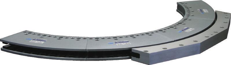

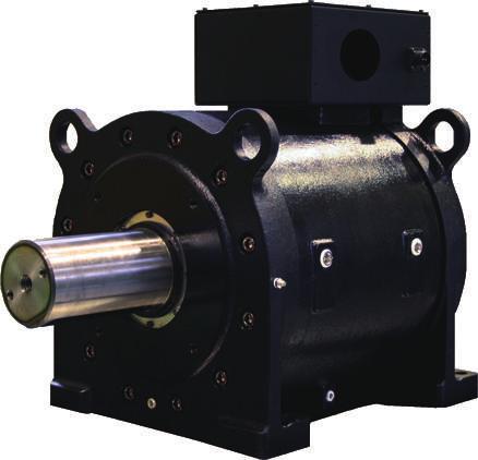

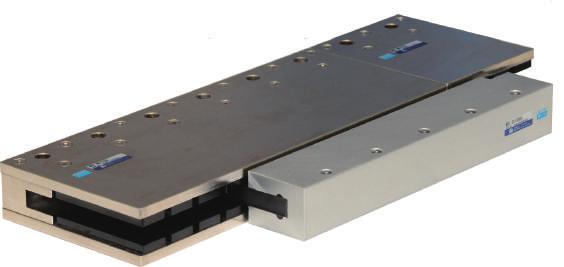

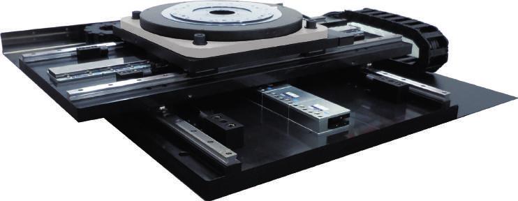

79 78
P.5 P.15 P.6 P.26 P.29 P.7 P.8 P.39 P.44 P.45 P.3 P.5 P.9 P.10 P.11 P.13 P.46 P.47 P.49 P.50 P.54 P.55 P.15 P.16 P.16 P.18
 1 P.15 P.26 P.39 P.29 P.5 P.6 P.8 P.7 P.44 P.45 P.46 P.47 P.49 P.5 P.54 P.55 P.6 P.61 P.62 P.63 P.65 P.66 P.67 P.69 P.73 P.76 P.76 P.79 P.8 P.81 P.82 P.3 P.5 P.9 P.1 P.11 P.13 P.15 P.16 P.16 P.18 P.26
Cable lead-out. Standard. Rear lead-out (Connecter used in models 58 and 65) Variation. Side lead-out is available. (Models 25, 32, and 40) Option
 Variation. Side lead-out is available. (Models 25, 32, and 40) Option") SHA Series The SHA series comprises AC servo actuators that integrate a thin speed reducer HarmonicDrive for precision control and a super flat AC servo motor. The SHA series features an unmatched compact
SHA Series The SHA series comprises AC servo actuators that integrate a thin speed reducer HarmonicDrive for precision control and a super flat AC servo motor. The SHA series features an unmatched compact
Optical encoder MEC22 HR
 Optical encoder MEC22 HR Description The MEC22 HR is a high resolution optical hollow shaft encoder that can be fixed quickly and easily on different sizes of motor shafts. The encoder provides two square
IP65 Splash and Dust Proof Stepping Motors
 IP5 Splash and Dust Proof Stepping Motors CE/UL Model Features These IP5 rated motors* have superior water and dust resistance, and can be safely utilized in harsh or wet environments such as in food processing
Sigma direct drive motors
 Ver. HRGE SERVOPK POWER SGMS-@ Sigma direct drive motors High torque motor for direct coupling to load High dynamic performance Gearless. Reduction of mechanic components Improved positioning accuracy
TRD-N/NH Series Incremental Encoders
 /N Series Encoders TRD-K TRD-K A TRD-GK TRD-J /N TRD-2E TRD-S/S Features Shaft and ollow Shaft type are available. Compact body with 5mm diameter and 35mm depth. Wide range of resolution from 1 to 2,5P/R.
HD25. Industrial Rugged Metal Optical Encoder Page 1 of 6. Description. Mechanical Drawing. Features
 Description HD25 Page 1 of 6 The HD25 is a rugged optical incremental shaft encoder designed for heavy-duty industrial applications. The housing, machined from a solid billet aluminum block and finished
Incremental encoders Redundant sensing, isolated blind hollow shaft ø mm, cone shaft ø17 mm pulses per revolution
 Features Robust, compact housing Two bearings with large distance, one at each end High shaft load up to 450 N Shock resistant up to 250 g Shaft insulation up to 2.8 kv Highest operating speed 10000 rpm
847H. Description. Features. Specifications
 847H Bulletin 847H High Performance Industrial Incremental Encoders provide code disk resolutions of up to 65536 pulses per revolution at a signal frequency response of 820 khz. The 847H can provide 65536
6th digit. 5th digit. 4th digit. Code Specifications 3 20-bit absolute (standard) D 20-bit incremental (standard) Design Revision Order
 D 20-bit incremental (standard) Design Revision Order") Rotary s Model Designations - 3 D Series st+nd digits 3rd digit th digit th digit th digit 7th digit st+nd digits Rated Output th digit Serial Encoder 7th digit Options Code 3 3 W W 9 8 W 3.3 kw.8 kw 3.9
Rotary s Model Designations - 3 D Series st+nd digits 3rd digit th digit th digit th digit 7th digit st+nd digits Rated Output th digit Serial Encoder 7th digit Options Code 3 3 W W 9 8 W 3.3 kw.8 kw 3.9
JR12 Jam Nut Mount Optical Encoder
 Improving the Quality of Life through the Power in Light JR12 Jam Nut Mount Optical Encoder QPhase Design Features: Replaces Size 15 Pancake Resolver Bearing design simplifies encoder attachment Resolutions
IXARC Incremental Encoder UCD-IPT M100-PRD. Interface Programmable Incremental. Configuration Tool UBIFAST Configuration Tool (Version 1.6.
 IXARC Incremental Encoder UCD-IPT00-08192-M100-PRD Interface Interface Programmable Incremental Programming Functions PPR (1-16384), Output, Counting Direction Configuration Tool UBIFAST Configuration
TRD-J Series Incremental Encoders
 Series Incremental Encoders Features mm thick shaft and ø5 mm body Vibration and shock resistant metal slit plate durable at 1, P/R Operating voltage ranging from 4.75 to 3 VDC Totem-pole output facilitating
Universal Radius Mounting Option. Fixed Radius Mounting Option
 F e a t u r e s Factory Set for Same Day Dispatch (1 to 65,536 Pulses Per Rev) 100 Degrees Centegrate cabability as standard Opto-ASIC Technology Any bore - up to 15mm bore (Metric) or (Imperial) The 60HA
 PWB encoders GmbH Am Goldberg 2 D-99817 Eisenach Germany Phone: +49 3691 72580-0 Fax: +49 3691 72580-29 info@pwb-encoders.com www.pwb-encoders.com 1 of 9 Description The ME22 is a reliable low cost optical
SGMMV. Rotary Servomotors SGMMV - A1 A 2 A 2 1. Model Designations. 6th. 5th digit. 1st+2nd digits. 7th digit. 4th digit. 3rd digit.
 Rotary s Model Designations - mini Series st+nd digits 3rd digit th digit th digit 6th digit 7th digit st+nd digits Rated Output th digit Design Revision Order 7th digit Options Code Code Code B3 3.3 W
LENORD. +BAUER... automates motion. GEL 2037 with heavy duty flange or tooth wheel adapter. Technical information Version General.
 GEL 2037 with heavy duty flange or tooth wheel adapter LENORD +BAUER... automates motion. Technical information Version 2014-07 General Multiturn absolute rotary encoders with a resolution of up to 25
RKF Series. Total Motion Control. Harmonic Drive actuator
 RKF Series Total Motion Control Harmonic Drive actuator P r e c i s i o n G e a r i n g & M o t i o n C o n t r o l RKF Series The RKF series is compact and includes high-torque AC servo actuators with
TRD-J Series Incremental Encoders
 Series Encoders eatures ong-lasting disign of mm shaft in ø5mm body. urable metal slit plate. Protection degree IP5 (dust proof) or IP65 (dust and splash proof). Wide voltage ranging from 4.75 to 3 VC.
Product Information. ERN 1085 Incremental Rotary Encoder with Z1 Track
 Product Information ERN 1085 Incremental Rotary Encoder with Z1 Track 02/2018 ERN 1085 Rotary encoder with mounted stator coupling Compact dimensions Blind hollow shaft 6 mm Z1 track for sine commutation
TETRA COMPACT - E AND FLEXI - PRO
 TETRA COMPACT - E AND FLEXI - PRO THE ENHANCED SERVO BUNDLE Motor Power Company introduces its new brushless servo bundle: TETRA COMPACT- ENHANCED, brushless servomotors, perfectly matched with the FLEXI-PRO
MDS-DM2 Drive System Selections
 MITSUBISHI READY MDS-DM2 Drive System Selections Digital AC servo and spindle drive system built into one package. The drive system can have up to 3 servos and 1 spindle. This will reduce cabinet space
Lexium integrated drives
 Description ILp for CANopen, PROFIBUS DP, RS ILA with AC synchronous servo motor Description ILA comprise control electronics with a fieldbus interface for CANopen DS, PROFIBUS DP or RS and an AC synchronous
Magnetic Encoder MEM 22
 Description The MEM 22 is a magnetic incremental encoder. He is a reliable low cost hollow shaft encoder that can be fixed quickly and easily on different sizes of motor shafts. The encoder MEM22 is designed
Incremental encoders Blind hollow shaft or cone shaft pulses per revolution
 Features TTL output driver for cable length up to 550 m Very high resistance to shock and vibrations Hybrid bearing for extended service life Shaft insulation up to.8 kv Large terminal box, turn by 80
60 mm sq. (2.36 inch sq.)
") 6 mm sq. (.36 inch sq.) 1.8 /step RoHS Unipolar winding, Connector type Unipolar winding, Dimensions for attaching NEMA3 are interchangeable (47.14 mm-pitch) Bipolar winding, Connector type p. 76 Bipolar
6 mm sq. (.36 inch sq.) 1.8 /step RoHS Unipolar winding, Connector type Unipolar winding, Dimensions for attaching NEMA3 are interchangeable (47.14 mm-pitch) Bipolar winding, Connector type p. 76 Bipolar
Harmonic Drive actuator
 Harmonic Drive actuator P r e c i s i o n G e a r i n g & M o t i o n C o n t r o l The RSF series servo actuator combines a high performance brushless servomotor with a high accuracy Harmonic Drive gearhead
56 mm sq. (2.20 inch sq.)
") 56 mm sq. (. inch sq.) 1.8 /step RoHS Unipolar winding, Lead wire type Bipolar winding, Lead wire type p. 7 Customizing Hollow Shaft modification Decelerator Encoder Varies depending on the model number
56 mm sq. (. inch sq.) 1.8 /step RoHS Unipolar winding, Lead wire type Bipolar winding, Lead wire type p. 7 Customizing Hollow Shaft modification Decelerator Encoder Varies depending on the model number
ILA2E572PC1A0 integrated drive ILA with servo motor V - EtherCAT - indus connector
 Characteristics integrated drive ILA with servo motor - 24..48 V - EtherCAT - indus connector Main Range of product Product or component type Device short name Motor type Number of motor poles 6 Network
The World of Motion Control
 PWB-Ruhlatec Industrieprodukte GmbH Siegburger Str.39a D-53757 Sankt Augustin Germany www.pwb-technologies.com info@pwb-technologies.com ME16 1 of 8 Rev.7.22 / 05.02.2007 Description The ME16 is a reliable
QR12. Output. A = Line Driver B = Line Driver ABZ/ Open Collector UVW C = Sin/Cos/ Line Driver UVW D = Sin/Cos/Open Collector UVW
 QR12 DESIGN FEATURES Low profile assembled height of 0.99" Bearing design simplifies encoder attachment Resolutions up to 20,000 lines per revolution SIN/COS outputs available up to 1250 LC 4, 6 or 8 pole
DG 60 L Incremental Encoder
 Incremental Encoder Features Incremental encoder with 60 mm outer diameter ugged die-cast aluminum housing Quadrature output with reference marker, complementary output signals Protection to IP 67 Square
MAGNETIC 2000 SERIES BEARINGLESS ENCODERS FOR LARGE SHAFTS
 MAGNETIC 2000 SERIES BEARINGLESS ENCODERS FOR LARGE SHAFTS Low-maintenance for large shafts Certain motors benefit from having the speed feedback sensor mounted directly on the main shaft. A bearingless
DGS 60, DGS 65 and DGS 66: Incremental Encoders for rough environmental conditions
 , 5 and : s for rough environmental conditions elect your individual encoder - Possible product variants: and mm solid shafts with servo flange or face mount flange, through or blind hollow shafts with
Data Sheet MEM 16. Incremental Encoder Magnetic
 Incremental Encoder Magnetic PWB encoders GmbH Am Goldberg 2 D-99817 Eisenach Germany Phone: +49 3691 72580-0 Fax: +49 3691 72580-29 info@pwb-encoders.com MEM16IE Rev.2.1 / 15.12.2016 info@pwb-encoders.com
Rotary Measurement Technology Incremental Encoders
 -20 to 60 C Temperature Shock/vibration resistant Short-circuit protection Reverse polarity protection High rotational speed Rugged Balanced, stainless-steel clamping rings, special bearing-shaft connection
Express Delivery. Axial. Connection
 HIGH RESOLUTION INCREMENTAL SOLID SHAFT ENCODER FOR INDUSTRIAL APPLICATIONS Resolution up to 50.000 pulses per turn External diameter 58 mm Shaft from Ø 6 to 12 mm Protection class IP67 according to DIN
SE22 Mini Encoder Data Sheet 5V TTL power supply optical model
 SE22 Mini Encoder Data Sheet 5V TTL power supply optical model 1 Description SE22 is a high performance, low cost, hollow shaft encoder family, very easy for assembly on shaft diameters set ranging from
LENORD. +BAUER... automates motion. Magnetic absolute rotary encoder GEL 2037 with heavy duty flange or tooth wheel adapter
 Magnetic absolute rotary encoder GEL 2037 with heavy duty flange or tooth wheel adapter LENORD +BAUER... automates motion. Technical information Version 01.12 General Multiturn absolute rotary encoders
5th digit. 4th digit. 6th digit. Design Revision Order. Shaft End. Code Specifications
 Rotary s Designations 2Without Gears - 0 D 2 Series st+2nd digits 3rd digit 4th digit 5th digit 6th digit 7th digit st+2nd digits Rated Output 5th digit Design Revision Order 7th digit Options Code 5 50
SGMJV. Rotary Servomotors SGMJV - 01 A D A 2 1. Model Designations. 2Without Gears. 1st+2nd digits. 3rd digit. 5th digit. 6th digit.
 Rotary s Designations 2Without s - D 2 Series st+2nd s rd 4th th th 7th st+2nd s Rated Output th Design Revision Order 7th Options Code W W C2 W 2 2 W 4 4 W W 8 7 W rd Power Supply Voltage Code th Code
RDrive 85 servo motors. User manual
 INTRODUCTION Rozum Robotics has designed its RDrive (RD) servo motors to enable precision motion control in industrial and commercial applications. This manual is intended for technicians and engineers
AC SERVO DRIVES SERIES. Rotary Servomotors. Certified for ISO9001 and ISO14001
 C SERVO DRIVES SERIES Rotary Servomotors Certified for ISO91 and ISO141 JQ-422 JQ-EM22 CONTENTS Rotary Servomotors SGMMV (ow Inertia, Ultra-small Size) 4 SGM7J (Medium Inertia, High-speed) 14 SGM7 (ow
DRS61: Incremental encoders, number of lines and zero pulse width freely programmable DRS60: Incremental Encoders with Zero-Pulse-Teach
 NEW DRS: Incremental encoders, number of lines and zero pulse width freely programmable DRS: s with Zero-Pulse-Teach Further highlights of this generation of encoders: Simple zero-pulse-teach by pressing
Motor Encoders. With Motor encoders Series M - Optimal control of motor feedback -
 Motor Encoders With Motor encoders Series M - Optimal control of motor feedback - Hengstler supplies the new high-performance motor encoder series M for use with brushless servo motors and stepper motors.
REGULACE AUTOMATIZACE BOR spol. s r.o.
 REGULACE AUTOMATIZACE BOR spol. s r.o. NOVÝ BOR CATALOG : HSM D.C. SERVO MOTORS All products of the company REGULACE AUTOMATIZACE BOR, spol. s r.o. (Ltd.) are certified by accredited authority for certification
LENORD. +BAUER... automates motion. Magnetic incremental encoder GEL 293 for heavy duty applications. Technical Information Version 04.
 Magnetic incremental encoder GEL 293 for heavy duty applications LENORD +BAUER... automates motion. Technical Information Version 04.14 General information High-resolution magnetic incremental rotary encoder
TETRA COMPACT LOW VOLTAGE BRUSHLESS SERVOMOTORS
 TETRA COMPACT LOW VOLTAGE BRUSHLESS SERVOMOTORS BRUSHLESS TECHNOLOGY FEATURES AND BENEFITS Synchronous brushless servomotor, permanently excited Rated output power from 60W to 800W Maximum servomotor speed
LENORD. +BAUER... automates motion. GEL 2351 with current or voltage interface. Technical information Version General. Features.
 GEL 2351 with current or voltage interface LENORD +BAUER... automates motion. Technical information Version 201-11 General Single turn absolute rotary encoder with a resolution of 16 bits Magneto-resistive
Technical data. General specifications. Measurement range min max. 360
 Model Number Features Very small housing High climatic resistance 12 Bit singleturn Analog output Surge and reverse polarity protection Description This absolute rotary encoder with internal magnetic sampling
Phone: Fax: Web: -
 ue to their sturdy bearing construction in Safety-ock esign, the Sendix 5000 and 500 offer high resistance against vibration and installation errors. The rugged housing, high protection level of up to
14 mm sq inch sq.
 Allowable Load Internal Wiring Rotation Direction P.56 General Specifications P.57 Motor Dimensions P.69 to 74 14 mm sq..55 inch sq. 1.8 /step winding Lead wire type winding Lead wire type Model number
PKP Series. Bipolar 1.8 and 0.9 Stepper Motors. with Encoders. Features. Product Lineup
 Bipolar. and.9 Stepper s PKP Series with s Introducing the new. Standard and.9 High Resolution PKP Series stepper motors with an incremental Line Driver or Voltage output type encoder pre-assembled. Features
Product Information. EQN 1337 F Absolute Rotary Encoder with Tapered Shaft for Fanuc Controls with i Interface
 Product Information EQN 1337 F Absolute Rotary Encoder with Tapered Shaft for Fanuc Controls with i Interface 11/2017 EQN 1337 F Rotary encoders for absolute position values Installation diameter 65 mm
TETRA COMPACT - E AND FLEXI - PRO THE ENHANCED SERVO BUNDLE
 TETRA COMPACT - E AND FLEXI - PRO THE ENHANCED SERVO BUNDLE Mo t or P ow e r Com pa n y www.m ot orpow e rc o. c om info@m ot orpow e rc o. i t All r ight s re se rve d. Comple t e or pa rt i a l re produ
Online data sheet. DBS60E-TECJD1024 DBS60 Core INCREMENTAL ENCODERS
 Online data sheet DS60ETECJD1024 DS60 Core C D E F H I J K L M N O P Q R S T Ordering information Type Part no. DS60ETECJD1024 DS60ETECJD1024 Other models and accessories www.sick.com/ds60_core Illustration
ADR-A Series Direct Drive Rotary Motor
 ADR-A Series Direct Drive Rotary Motor Direct drive, brushless motor fully integrated with encoder and bearing Low cogging torque Low speed and high speed windings Precise homing through index pulse ADR110
RoHS. High shaft load capacity. Shock / vibration resistant
 Due to their sturdy bearing construction in Safety Lock Design, the Sendix 5000 and 5020 offer high resistance against vibration and installation errors. The rugged housing, high protection level of up
NPN PNP NPN PNP NPN PNP
 Cam Positioner Low-Cost, High-Performance Electronic Cam Switch for Use with OMRON E6F Rotary Encoder Control outputs can be programmed to turn ON/OFF in 1 units of rotary encoder shaft rotation Handles
Committed to Premium Quality. AC Servo System Catalog
 Committed to Premium Quality AC Servo System Catalog Company Profile CONTENTS DB100 Series AC Servo System 03 Application fields 04 Servo Driver Product Description 05 Servo Motor Product Description 07
Product Information. EBI 1135 Absolute Rotary Encoder, Multiturn Feature via Battery-Buffered Revolution Counter
 Product Information EBI 1135 Absolute Rotary Encoder, Multiturn Feature via Battery-Buffered Revolution Counter December 2012 EBI 1135 Inductive rotary encoder without integral bearing for integration
Features & Benefits 360, 512, 720, 1000, 1024, 1440, 1800, 2000, 2048, 2880, 3000, 3600, 4000, 4096, 5000, 5120, 6000, 7200, 8000, 8192, 9000, 10000
 CP-800/900 Series Size-25 Housed Rotary Optical Encoders Solid or hollow shaft, incremental, sine/cosine, or absolute format Allied Motion s CP800/900 series are size-25 (2.5 in. (63.5mm)) rotary optical
Technical data. General specifications. Linearity error ± 0.1 Electrical specifications Operating voltage U B
 Model Number SYNCHRON SERIELLES INTERFACE Features Very small housing Up to 32 Bit multiturn SSI interface Free of wear magnetic sampling High resolution and accuracy Description The ENA36IL series are
Rotary Position Technology Incremental Encoders
 -40 to 80 C Temperature Shock/vibration resistant Short-circuit protected Reverse polarity protection High rotational speed Rugged Balanced, stainless-steel clamping rings, special bearing-shaft connection
Standard Sendix 5000 / 5020 (shaft / hollow shaft) Push-Pull / RS422 / Open collector. Robust performance. Many variants
 Push-Pull / RS422 / Open collector. Robust performance. Many variants") ue to their sturdy bearing construction in Safety-ock esign, the Sendix 5000 and 500 offer high resistance against vibration and installation errors. The rugged housing, high protection level of up to
ue to their sturdy bearing construction in Safety-ock esign, the Sendix 5000 and 500 offer high resistance against vibration and installation errors. The rugged housing, high protection level of up to
Data Sheet MEM 22. Incremental Encoder Magnetic
 Incremental Encoder Magnetic PWB encoders GmbH Am Goldberg 2 D-99817 Eisenach Germany Phone: +49 3691 72580-0 Fax: +49 3691 72580-29 info@pwb-encoders.com MEM 22 IE Rev.1.9 / 16.05.2017 info@pwb-encoders.com
Electric Actuator/ High Rigidity Slider Type
 INFORMATION Electric Actuator/ High Rigidity Slider Type RoHS Clean Room Specification ISO Class 4 * (Class ) *2, *3! Built-in vacuum piping Possible to mount the main body without removing the external
CC-Link Compatible AC Servo Amplifier <MR-J3-T type> with Built-in Positioning Function
 MO LM/ G T P R M Fn SHIFT ES E B 1STEP. F PRU03 TEST F ST OP RESET General-Purpose Servo MELSERO-J3 ew Product Release S0-E -Link ompatible Servo mplifier with Built-in Positioning Function
3Specifications CHAPTER THREE IN THIS CHAPTER
 CHAPTER THREE 3Specifications IN THIS CHAPTER Drive Specifications SM and NeoMetric Motor Specifications SM and NeoMetric Motor / Curves SM and NeoMetric Motor Dimensions SM and NeoMetric Encoder Specifications
Online data sheet. ACM60B-S1KE13x06 ACM60 ABSOLUTE ENCODERS
 Online data sheet ACM60B-S1KE1x06 ACM60 A B C D E F H I J K L M N O P Q R S T Illustration may differ Detailed technical data Performance Number of steps per revolution Number of revolutions Ordering information
Optical Encoders CP-800/900 Series Size-25 Housed Rotary Optical Encoders Solid or, incremental, sine/cosine, or absolute format Allied Motion s CP-80
 Cs GROUP SIX LehriAG Avim SEI Ki CO LTD. ^,1 Motion Computer Optical Products, Inc. COPI 800 & 900 ENCODERS - Incremental - Absolute - Sinusoidal Contact Us! 800-433-3434 USA Email info@grp6.com Optical
3. HIWIN rotary tables TMS
 CRD Devices Ltd All Saints Industrial Estate, Shildon, Co, Durham, DL4 2RD Tel: +44 ()1388 7784 Fax: +44 ()1388 7788 E: sales@crd-devices.co.uk W: www.crd-devices.co.uk 3. HIWIN rotary tables TMS 3.1 Characteristics
Online data sheet AFS60A-BJPA AFS/AFM60 SSI ABSOLUTE ENCODERS
 Online data sheet FS0-JP FS/FM0 SSI FS0-JP FS/FM0 SSI C D E F H I J K L M N O P Q R S T Ordering information Type Part no. FS0-JP 09 Other models and accessories www.sick.com/fs_fm0_ssi Illustration may
Online data sheet DFS60B-S4PA00S74 DFS60 INCREMENTAL ENCODERS
 Online data sheet DFS60B-S4PA00S74 DFS60 A B C D E F Illustration may differ Ordering information Type Part no. DFS60B-S4PA00S74 1081183 Other models and accessories www.sick.com/dfs60 H I J K L M N O
XXXX e. X d.. X X X a
 The Heavy uty incremental encoder type 0H boasts a high degree of ruggedness in a very compact design. Its special construction makes it perfect for all applications in very harsh environments. / RoHS
QUANTUM DEVICES,INC. QPhase ISO 9001 DESCRIPTION TYPICAL APPLICATIONS DESIGN FEATURES
 QUANTUM DEVICES,INC. Improving the Quality of Life through the Power in Light QPhase DESCRIPTION Quantum Devices, Inc. Model QDH20 provides an improved feedback solution in applications typically using
Rotary encoders. absolute / optical. Bright ideas in the measurement of rotation: robust, precise, versatile.
 Rotary encoders absolute / optical right ideas in the measurement of rotation: robust, precise, versatile. Absolute encoder WK02/1 Hollow shaft WK02/1 - robust single-turn angle encoder with through hollow
Incremental Encoder for special applications
 Model Number Features Up to 50,000 ppr Extended temperature range Industrial standard housing Ø58 mm Servo or clamping flange 10 V... 30 V with short-circuit proof push-pull output Description High performance
XXXX e. X d.. X X X a
 The Heavy Duty incremental encoder type 0H boasts a high degree of ruggedness in a very compact design. Its special construction makes it perfect for all applications in very harsh environments. / RoHS
Rotary Encoder System Compact Model Range
 we set the standards RIK Rotary Encoder System Compact Model Range 2 Incremental rotary encoder Features Compact design, consisting of scanning head with round cable, 15pin D-sub connector and grating
QR12 (1.22 ) Diameter Optical Encoder
 Diameter Optical Encoder") Improving the Quality of Life through the Power in Light QPhase QR12 (1.22 ) Diameter Optical Encoder Design Features: Low profile assembled height of Bearing design simplifies encoder attachment Resolutions
Improving the Quality of Life through the Power in Light QPhase QR12 (1.22 ) Diameter Optical Encoder Design Features: Low profile assembled height of Bearing design simplifies encoder attachment Resolutions
Material: Weight: Bearing Life: Shaft Speed: Starting Torque: Mass Moment of Inertia: Shaft Loads:
 Shaft Encoder - Ø 50 mm Shaft: Ø 6 mm to Ø 12 mm Resolution up to 12.500 ppr IP 65 (IP 67 option) Formerly named 2R or 2R-3L Automation / Electrical Specifications Code: Resolution: Supply Voltage: Voltage:
MAE3. Absolute Magnetic Kit Encoder Page 1 of 8. Description. Mechanical Drawing. Features
 Description MAE3 Page 1 of 8 The MAE3 is an absolute magnetic kit encoder that provides shaft position information over 360 of rotation with no stops or gaps. This magnetic encoder is designed to easily
Technical data. General specifications. Linearity error ± 0.1 Functional safety related parameters MTTF d 700 a at 40 C Mission Time (T M ) L 10
 L 10") Model Number SYNCHRON SERIELLES INTERFACE Features Solid shaft SSI interface Up to Bit multiturn Free of wear magnetic sampling High resolution and accuracy Additionally push buttons for preset function
Model Number SYNCHRON SERIELLES INTERFACE Features Solid shaft SSI interface Up to Bit multiturn Free of wear magnetic sampling High resolution and accuracy Additionally push buttons for preset function
A02H Encoder for Vector Motor Application
 A02H Encoder for Vector Motor Application NEMA C-Face Accessories Robust Bearing Design Long Life BTR Lip Seals 6000 RPM Continous Duty M12 eurofast Connector www.turck.com The A02H Kübler by TURCK 3.5
Absolute Encoders - Singleturn
 The Sendix 5 and Sendix 7 singleturn encoders with SSI or BiSS-C interface and optical sensor technology can achieve a resolution of max. 7 bits. These encoders are also available with an optional SinCos
Technical data. General specifications. Linearity error ± 0.1 Functional safety related parameters MTTF d 700 a at 40 C Mission Time (T M ) L 10
 L 10") Model Number SYNCHRON SERIELLES INTERFACE Features Recessed hollow shaft SSI interface Up to Bit multiturn Free of wear magnetic sampling High resolution and accuracy Additionally push buttons for preset
Model Number SYNCHRON SERIELLES INTERFACE Features Recessed hollow shaft SSI interface Up to Bit multiturn Free of wear magnetic sampling High resolution and accuracy Additionally push buttons for preset
J1 Line APPLICATION FEATURES DESCRIPTION RUGGED-DUTY SHAFTED ENCODERS
 J1 Line RUGGED-DUTY SHAFTED ENCODERS APPLICATION Joral rugged-duty encoders are perfect for use in harsh applications where dirt, moisture, vibration and shock are factors, such as off-road vehicles, conveyors,
4 / 24,5 2,6 / steel, black coated. clockwise, viewed from the front face. ø15,9 ø17-0,052 ø6-0,05 8,1 ±0,3 2, T
 DC-Micromotors Precious Metal Commutation 4, mnm For combination with (overview on page 4-5) Gearheads: 5, 6, 6/7 Encoders: IE 6... 5 Series 4 74... SR Nominal voltage Terminal resistance Output power
Online data sheet DFS60A-TEPZ00S09 DFS60 INCREMENTAL ENCODERS
 Online data sheet DFS60A-TEPZ00S09 DFS60 A B C D E F H I J K L M N O P Q R S T Illustration may differ Detailed technical data Features Special device Specialty Ordering information Other models and accessories
SmartStep servo motors
 HARGE R7M-A@, R7M-AP@ SmartStep servo motors The smart alternative to stepper motors SmartStep motors can be controlled by SmartStep drive and XtraDrive ylindrical and flat servo motor types are available
Optical Kit Encoder Page 1 of 5. Description. Features
 Description Page 1 of 5 The E5 Series rotary encoder has a molded polycarbonate enclosure with either a 5-pin or 10-pin latching connector. This optical incremental encoder is designed to easily mount
Online data sheet AFS60B-S4PA AFS/AFM60 SSI ABSOLUTE ENCODERS
 Online data sheet FS60-S4P032768 FS/FM60 SSI FS60-S4P032768 FS/FM60 SSI C D E F Ordering information Type Part no. FS60-S4P032768 1037483 Other models and accessories www.sick.com/fs_fm60_ssi Illustration
The quadrature signals and the index pulse are accessed through five inch square pins located on 0.1 inch centers.
 Quick Assembly Two and Three Channel Optical Encoders Technical Data HEDM-550x/560x HEDS-550x/554x HEDS-560x/564x Features Two Channel Quadrature Output with Optional Index Pulse Quick and Easy Assembly
Incremental encoders With blind or through hollow shaft pulses per revolution programmable
 Features Size mm Precise optical sensing Output signal level programmable (TTL or HTL) Blind or through hollow shaft, ø8 15 mm Connection axial, radial or tangential Pulses per revolution 1...65536, programmable
New Servo Concept: Junma
 New Servo Concept: Junma Junma uses the world s premier servo technology to provide unmatched performance with a quick and efficient setup. This totally new plug and play design concept requires no parameter
EC35. Optical Commutation Kit Encoder Page 1 of 7. Description. Mechanical Drawing. Features
 Page 1 of 7 Description The EC35 quick assembly optical commutation encoder is designed for high volume, low cost, OEM motion control applications. The EC35 provides A/B/Z incremental outputs and U/V/W
Incremental encoders With blind or through hollow shaft pulses per revolution programmable
 Features Size ø58 mm Precise optical sensing Output signal level programmable (TTL or HTL) Blind or through hollow shaft, ø8 15 mm Connection axial, radial or tangential Pulses per revolution 1...65536,
Agilent AEDA-3300 Series Ultra Miniature, High Resolution Incremental Kit Encoders Data Sheet
 Description The AEDA-3300 series are high performance, cost effective, three-channel optical incremental encoder modules with integrated bearing stage. By using transmissive encoder technology to sense
Technical data. General specifications V DC Power consumption P 0. 1 W Time delay before availability t v
 Model Number SYNCHRON SERIELLES INTERFACE Features Very small housing Up to 32 Bit multiturn SSI interface Free of wear magnetic sampling High resolution and accuracy Description The ENA36IL series are