GROUND-FAULT PROTECTION ON RESISTANCE-GROUNDED POWER-DISTRIBUTION SYSTEMS WITH ADJUSTABLE-SPEED DRIVES 1. Modified_103007
|
|
|
- Dominick Harrington
- 6 years ago
- Views:
Transcription

1 GROUND-FAULT PROTECTION ON RESISTANCE-GROUNDED POWER-DISTRIBUTION SYSTEMS WITH ADJUSTABLE-SPEED DRIVES 1
2 TWO BASIC PROBLEMS 1. Prevent nuisance or false trips because of noise on loads or feeders without an ASD. 2. Reliably detect a ground fault on an ASD-driven motor load. 2
3 SOME BACKGROUND 3
4 SENSING GROUND FAULTS on a grounded electrical system THE BEST WAY TO DETECT A GROUND FAULT: CURRENT SENSING - usually with a zero-sequence core-balance current transformer (CT or ZSCT) - permits selective coordination and ease of finding a fault 4


5 Q: What is a Core-Balance Zero-Sequence CT? Answer: Any window-type current transformer is a core-balance zero-sequence CT when all current-carrying conductors are passed through the CT window. Specialized CT s for low-level fault detection are available (EFCT-x, SE-CS30-x). 5
6 LIMITING PHYSICAL FACTORS LOW-LEVEL GROUND-FAULT DETECTION: PHYSICAL LIMITING FACTORS 1.) System Capacitance 2.) Unbalanced 1-Phase Loads 3.) Current-Sensor Limitations 4.) Harmonic Components 1, 2, & 4 result in current flowing to earth in an unfaulted system. 3 can result in incorrect indication of a ground fault. 6

7 SYSTEM CAPACITANCE Capacitor Noun: A device used to store an electric charge, consisting of one or more pairs of conductors separated by an insulator. All electrical systems have phase-to-ground capacitance distributed throughout the system modeled here as lumped values in a simple singleload system 7


8 CHARGING CURRENT 2 1 Definition of charging current: The current that flows when one phase of an ungrounded system is shorted to ground Note: A core-balance CT at 1 will measure charging current A core-balance CT at 2 will measure zero 8
, protection must be set above the charging current level Protection level can be set below charging current if sympathetic tripping (alarming) is acceptable")
9 CHARGING CURRENT & SYMPATHETIC OPERATION A4 A4 READS I Z A core-balance CT on an unfaulted feeder will detect its feeder s charging current when a ground fault occurs on another feeder. To avoid sympathetic tripping (alarming), protection must be set above the charging current level Protection level can be set below charging current if sympathetic tripping (alarming) is acceptable Charging current does not flow to the system neutral 9

10 CAPACITANCE UNBALANCE 51G Balanced Phase-to-Ground Capacitance: Xa=Xb=Xc Phase capacitive currents are equal Core-balance CT reads zero. Unbalanced Phase-to-Ground Capacitance: Xa Xb Xc Phase capacitive currents are not equal Core-balance CT reads a finite value 10


11 VOLTAGE UNBALANCE Voltage Unbalance, Van Vbn Vcn: May be the result of unbalanced singlephase utility loads Voltage unbalance combined with capacitance unbalance forces capacitive current unbalance resulting in steady-state zero-sequence current. These affects are usually small, but may affect low-level earth-fault current detection 11
12 UNBALANCED LOAD CURRENTS Do unbalanced load currents cause ground-fault trips? 51G No. If there is no leakage to ground, unbalanced load currents add to zero, therefore no core-balance CT output. Ia + Ib + Ic = 0 Balanced or Unbalanced 12


13 CURRENT TRANSFORMERS Practical Current-Transformer Considerations: Excitation Current minimum primary current that will give an output. can require specialized ZSCT. Saturation output current not proportional to large primary current (high-level fault) Local Saturation output with no zero-sequence current surge currents and poor conductor placement correct with proper conductor location and flux conditioner 13
14 HARMONIC FREQUENCIES Often result from use of Adjustable-Speed Drives and Solid-State Starters ASD s build waveforms in a series of steps. Each step includes harmonic frequencies. Phase Conductor Earth X C XC = 1 2πfC Where C=capacitance f=frequency Capacitive impedance (X C ) decreases at higher frequencies Current per volt increases at higher frequencies The affect of capacitive and voltage unbalance are greater at higher frequencies current flowing to ground, with no fault present 14

15 Building a Sine Wave DC Voltage is switched on and off Resulting AC current is a noisy sine wave. A real example 15
16 TRIPLEN HARMONICS: A Special Case In 3-phase systems third-order harmonics are in-phase their values add; they do not cancel + + = Example: Fundamental & 3rd harmonic Can cause nuisance ground-fault tripping 16
17 Harmonic Currents Harmonic currents can flow to earth through system capacitance and cause nuisance earthfault tripping Triplen harmonics are detected by core-balance current transformers because they don t cancel Solution: set ground-fault pickup level above harmonic current background level, or filter the harmonics with a protective device that responds only to the fundamental frequency 17
18 Required Filter Characteristics Filtering Requirements: Respond to the fundamental frequency to detect true zero-sequence ground-fault current Do not respond to dc-offset caused by starting motors Do not respond to harmonic-frequency components The Discrete Fourier Transform has these characteristics Ip = 2 m m 1 n= 0 2πn I(n) sin m 18
19 Example of 50-Hz Fundamental with 150-Hz Component 2-component Signal Amperes Hz Hz Sample -2 Time (ms) 50 Hz Component 150 HzComponent EF Current Waveform Samples Sampler is set to take a known number of samples per 50 Hz cycle (here 20 samples/cycle) 19
20 DFT Measures the Desired Frequency Sample Number (n) 50 Hz Comp. I f (n) 150 Hz Comp. Sampled Value I(n) I f (n)sin(2*pi*n/20) I(n)sin(2*pi*n/20) DFT of 50 Hz component = DFT of signal = The result for the multiple-frequency signal is the same as the result for the 50 Hz component Only one cycle is required to calculate earth-fault current, and is updated every sample 20


21 A SOLUTION FOR AVOIDING FALSE TRIPS IN HARMONIC-RICH SYSTEMS Use a ground-fault protection device incorporating sampling technology and DFT processing for: DC-offset filtering Harmonic filtering Speed - one cycle maximum detection time Examples are: SE-701, SE-704, SE-330, MPU-32, MPS, FPU-32, FPS 21
22 What about detecting a ground fault in a VFD circuit when the VFD is operating outside of Hz? Another filtering algorithm is necessary; Peak Detection. 22
23 THE TROUBLE WITH VFD BUILT-IN GROUND-FAULT PROTECTION MANY LOW-VOLTAGE DRIVES HAVE A FIXED (Non-Adjustable) GROUND-FAULT PROTECTION LEVEL. Often presumes a solidly grounded system Often a large percentage (eg: 50%) of rated current Often not compatible with a high-resistance grounded system THESE DRIVES REQUIRE SUPPLEMENTAL GROUND-FAULT PROTECTION 23

24 Why is Inability to Detect a GF in an ASD System a Problem? 24

25 Why is Inability to Detect a GF in an ASD System a Problem? 25
 Some type of fault occurred with The Result:")
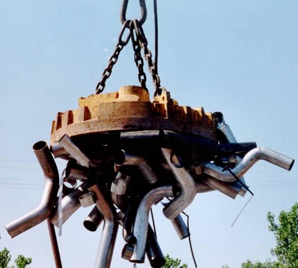
26 What Happened Here? The System: Low-voltage Variable-speed drive 5-A neutral-grounding resistor (NGR) Some type of fault occurred with The Result: Melted copper and steel Luckily, no fire Ground was obviously involved But the ground fault was not detected! 26
27 What Happened Here? The System: Low-voltage Variable-speed drive 5-A neutral-grounding resistor (NGR) Could the damage be the direct result of the ground fault? No. P = I 2 R and I GF 5 A. Furthermore, for 5 A to flow, the fault impedance R must = 0 Ω (so P=0). As fault impedance rises, current decreases and power dissipation at the fault is small. Fault Power Dissipation 600-Vll, 5-A NGR Watts Fault Impedance (Ohms)
28 What Happened Here? A Theory A phase-to-winding connection became disconnected in the terminal box, but electrical continuity was maintained by (hi-impedance) contact with the grounded terminal-box cover. 51G > 5 A Motor I θ = I motor + 5 A, max VFD I GF = 5 A max This fault wouldn t cause an overcurrent trip And the ground fault was not detected 28
29 THE CHALLENGE IN VFD GROUND-FAULT PROTECTION CHALLENGE: RELIABLY DETECT A LOW- LEVEL GROUND FAULT ACROSS VFD OPERATING-FREQUENCY RANGE WITHOUT NUISANCE TRIPS. BIG QUESTION WHERE TO PUT THE CT? LINE SIDE? LOAD SIDE? WE DID SOME TESTING; and invented a new product 29

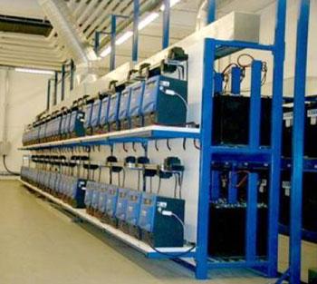
30 Littelfuse Startco R&D Lab VFD Ground-Fault Test Setup We set up a system with an NGR-grounded three-phase supply to a VFD feeding a motor, with a controlled ground fault, protection relays, and instrumentation 30
31 Littelfuse Startco R&D Lab VFD Ground-Fault Test Setup 31

32 Littelfuse Startco R&D Lab VFD Ground-Fault Test Setup Analog outputs from three SE-701 s were recorded. EFCT-1 Current Transformers were input devices. 32


33 Littelfuse Startco R&D Lab VFD Ground-Fault Test Setup An adjustable decade box was used to simulate a ground fault at various system locations. Digital RMS meters and a power analyzer were used to confirm SE-701 Ground Fault Monitor readings. 33

34 Sample 1: No Ground Fault VFD Phase-Voltage Spectrum: 30 Hz No Filter Phase X C Earth VL-G XC = 1 2πfC 34

35 Sample 1: No Ground Fault VFD Phase-Voltage Spectrum: 30 Hz 500-Hz Low-Pass Filter VL-G 35

36 Sample 2: System with a Ground Fault VFD Ground-Fault Spectrum: 60 Hz, 0.3 A No Filter VL-G IL-G VN-G IN-G 36

37 Sample 2: System with a Ground Fault VFD 60 Ground-Fault Hz Sample with Spectrum: 60 Hz, 0.3 A 500-Hz 500-Hz Low-Pass Low-Pass Filter Filter VL-G IL-G VN-G IN-G 37

38 Sample 3: System with a Ground Fault VFD Ground-Fault Spectrum: 10 Hz, 1 A No Filter VL-G IL-G VN-G IN-G 38

39 Sample 3: System with a Ground Fault VFD 10 Ground-Fault Hz Sample with Spectrum: 10 Hz, 1 A 500-Hz 500-Hz Low-Pass Low-Pass Filter Filter VL-G IL-G VN-G IN-G 39

40 SE-70x Monitors Have a Filter-Selector Switch SE-701 top view 40
41 SE-70x Filter Characteristics SE-70X Frequency Response Variable Frequency Peak Detection SE-70X Frequency Response Fixed Frequency 50/60 Hz DFT Filter Output Frequency (Hz) Filter Output Frequency (Hz) Peak-Detection Filter (labeled as Variable Frequency) DFT Filter (labeled as Fixed Frequency) 41
42 What about CT Location? A Littelfuse Startco Ground-Fault Monitor can be installed upstream of the drive. REALLY?? 42
43 Yes. Really. A VFD DOES NOT ISOLATE THE LOAD FROM THE SUPPLY Drive Frequency (Hz) Fault Current (ma) (No Filter) NGR Current (ma) SE-701 Filter Selection Upstream SE-701 Downstream SE-701 NGR SE DFT DFT DFT DFT DFT
44 Yes. Really. Drive Frequency (Hz) A VFD DOES NOT ISOLATE THE LOAD FROM THE SUPPLY Fault Current (ma) (No Filter) NGR Current (ma) SE-701 Filter Selection Upstream SE-701 Downstream SE-701 NGR SE Peak Peak Peak Peak Peak Peak
45 A VFD Does Not Isolate the Load from the Supply ~ M 45
46 Ground-Fault Pickup Setting Guide 1 SE-701 Frequency Response SVX9000 Drive 0.9 Normalized Response Drive Output Frequency From the chart, multiply the desired pickup at a frequency by the Normalized Response Value. 46
47 What About a DC-Bus Fault? Can an AC-sensing relay detect a DC fault? 47
48 How a VFD Makes DC from AC: Start with Full-Wave Rectification Show four waveforms. 1-phase 60-hz sine, 3-phase 60-hz sine, rectified 1 and 3-phase sine Single-Phase Sine Wave On Average, the value is 0 Full-Wave Rectified Singe-Phase Sine Wave On Average, the value is +ve 48
49 How a VFD Makes DC from AC: Start with Full-Wave Rectification, 3θ Three-Phase Sine Waves On Average, the value is 0 Full-Wave Rectified Three-Phase Sine Waves On Average, the value is +ve 49
50 DC from AC AC Ripple DC 50

51 VFD Negative DC-Bus Fault, 500 ma VL-G IL-G VN-G IN-G All of the measurements show the 180-Hz ripple. 51

52 DC Fault Spectrum Analysis 52

53 DC Fault Spectrum Analysis 180 Hz and Harmonics 53
54 ONE SOLUTION FOR TWO PROBLEMS FEEDER 1 LOAD 1 SE G VFD LOAD 2 SE G FEEDER 2 54
 For ASD circuits, use a detection device with a low-pass filter 0.3 0.2 0.")
55 SOLUTIONS FOR GROUND-FAULT DETECTION in an HRG SYSTEM with ASD s RUNNING NEAR LINE FREQUENCY For non-asd circuits, use a detection device with a narrow band-pass filter 1.2 SE-70X Frequency Response Fixed Frequency 50/60 Hz DFT Filter Output Frequency (Hz) For ASD circuits, use a detection device with a low-pass filter SE-70X Frequency Response Variable Frequency Peak Detection Filter Output Frequency (Hz) 55
 1.2 SE-70X Frequency Response Variable Frequency Peak Detection 1.1 1 0.9 Filter Output 0.8 0.7 0.6 0.5 0.4 0.3 0.2 0.")
56 SOME ASD S ARE USED AT VERY LOW SPEEDS <20 Hz 1.2 SE-70X Frequency Response Fixed Frequency 50/60 Hz DFT Filter Output Frequency (Hz) 1.2 SE-70X Frequency Response Variable Frequency Peak Detection Filter Output Frequency (Hz) 56
57 SOMETIMES A CONVENTIONAL GROUND- FAULT RELAY WON T DO SOMETIMES ACCURATE DC-to-60 Hz MEASUREMENT IS NECESSARY SOMETIMES ACCURATE HIGH-FREQUENCY MEASUREMENT IS NECESSARY 57
58 SE-70x Filter Characteristics SE-70X Frequency Response Variable Frequency Peak Detection SE-70X Frequency Response Fixed Frequency 50/60 Hz DFT Filter Output Frequency (Hz) Filter Output Frequency (Hz) 400 Hz Peak-Detection Filter (labeled as Variable Frequency) 1000 Hz 90 Hz DFT Filter (labeled as Fixed Frequency) 58

59 Introducing the EL731 EL731 AC/DC SENSITIVE EARTH-LEAKAGE RELAY 59
60 THERE IS A NEW APPROACH TO WIDE-BAND CURRENT MEAUSUREMENT THE EL731 accurately measures ground-fault current in the frequency range of 0 to 6 khz using conventional CT s AC/DC EARTH-LEAKAGE RELAY 60
61 Benefit #1 Provides low frequency to high frequency protection capability with one relay 0 to 6 khz EL731 Frequency Response SE-731 Frequency Response Normalized Response CT1 CT Frequency (Hz) 61
62 AC/DC EARTH-LEAKAGE RELAY CURRENT TRANSFORMER #1 CT1 MEASURES 0 TO 100 Hz 0 Hz = DC CT1 IS A STANDARD SENSITIVE EARTH-FAULT CT AND A DCCT USED ALONE OR WITH CT2 30 T0 5,000 ma SETTING RANGE EFCT-SERIES 62
63 AC/DC EARTH-LEAKAGE RELAY CURRENT TRANSFORMER #2 CT2 MEASURES 20 TO 6,000 Hz A STANDARD SENSITIVE EARTH-FAULT CT USED ALONE OR WITH CT1 30 T0 5,000 ma SETTING RANGE EFCT-SERIES 63
64 CT1 AND CT2 USE ONE OR BOTH COMBINED 0 TO 6,000 HZ FREQUENCY RESPONSE 64

65 Benefit #2 EFCT series CT used on previous applications can be re-used. Upgrade SE-701 applications. 65

66 Benefit #3 Separate Alarm and Trip relay outputs 3 programmable Form-C relays Early detection of alarm conditions allows prevention of extended downtime. 66
67 DC Applications 67
68 DC Application Must be grounded DC supply. 68
69 Benefit # 4 Feature: Ability to detect DC faults with a CT Benefit provides ability to locate the fault on a grounded-dc system. Improves upon previous DC ground-fault detection methods that would only tell you the system had a fault and possibly which bus was faulted. (SE-601) 69


70 But Wait There s more A fan cooled motor operated at low speed draws less air over the windings. Less cooling equates to higher winding temperature. 70
71 Feature and Benefit #5 The only ground-fault relay on the market with temperature protection. RTD or PTC Thermistor input for temperature measurement and protection. Allows measurement of motor, load or drive temperature. Many drives operate motors at lower speed (less cooling) but most do not offer temperature protection. 71

72 Features and Benefits #6 and #7 Communications module available to send info to data network. Flash upgradeable via optional communication adapter. Allows field modification of firmware if ever required. 72
73 Feature and Benefit #8 Password Protection 1 st of our ground-fault relays with this feature. 73

74 Features and Benefits #9 and #10 Metering on the door. 2-Line OLED display Panel-mount adapter not required for door mounting. No PMA-55 or PMA-60 required. Optionally available surface-mount adapter 74
75 Accessories 75
76 EL731 Benefits Reviewed 1. Full Frequency Coverage 2. Re-use existing EFCT series CT 3. Detection and fault location on DC systems 4. Separate Trip and Alarm Setpoints 5. Overtemperature Protection 6. Communications Capable GF relay 7. Firmware Upgradeable 8. Password Protected 9. Panel Mount Ready; optional surface mounting 10. Metering 76

77 Ground-Fault Protection for VFD s on High-Resistance-Grounded Systems SE-701 Ground-Fault Monitor Pickup: 50 ma to?? A SE-704 Earth-Leakage Monitor Pickup: 10 ma to 5 A EL731 AC/DC Sensitive Earth-Leakage Relay Pickup: 30 ma to 5 A Frequency Response: 32 to 86 Hz, 20 to 420 Hz Frequency Response: 0 to 90 Hz, 20 to 90 Hz, 20 to 3,000 Hz, 190 to 6,000 Hz, 0 to 6,000 Hz 77
Motor Protection. May 31, Tom Ernst GE Grid Solutions
 Motor Protection May 31, 2017 Tom Ernst GE Grid Solutions Motor Relay Zone of Protection -Electrical Faults -Abnormal Conditions -Thermal Overloads -Mechanical Failure 2 Setting of the motor protection
SE-502 MANUAL GROUND-FAULT GROUND-CONTINUITY DETECTOR
 SE-502 MANUAL GROUND-FAULT GROUND-CONTINUITY DETECTOR March 5, 2002 PRELIMINARY 1 Publication: SE-502-M Document: S95-C502-00000 Printed in Canada. Copyright 2002 by Startco Engineering Ltd. All rights
thepower to protect the power to protect i-gard LITERATURE Low and medium voltage
 thepower to protect i-gard LITERATURE Low and medium voltage distribution systems Arc Flash Hazards and High Resistance Grounding Grounding of Standby and Emergency Power Systems Neutral Grounding Resistors
Multimeter 500CVD21 RTU500 series
 Remote Terminal Units - Data sheet Multimeter 500CVD21 RTU500 series CT/VT interface with 4 voltage and 24 current inputs for direct monitoring of 3/4 wire 0 300 V AC (line to earth), 0...500 V AC (phase
APQline Active Harmonic Filters. N52 W13670 NORTHPARK DR. MENOMONEE FALLS, WI P. (262) F. (262)
 F. (262)") APQline Active Harmonic Filters N52 W13670 NORTHPARK DR. MENOMONEE FALLS, WI 53051 P. (262) 754-3883 F. (262) 754-3993 www.apqpower.com Power electronic equipment and AC-DC power conversion equipment contribute
APQline Active Harmonic Filters N52 W13670 NORTHPARK DR. MENOMONEE FALLS, WI 53051 P. (262) 754-3883 F. (262) 754-3993 www.apqpower.com Power electronic equipment and AC-DC power conversion equipment contribute
Bus protection with a differential relay. When there is no fault, the algebraic sum of circuit currents is zero
 Bus protection with a differential relay. When there is no fault, the algebraic sum of circuit currents is zero Consider a bus and its associated circuits consisting of lines or transformers. The algebraic
The Importance of the Neutral-Grounding Resistor. Presented by: Jeff Glenney, P.Eng. and Don Selkirk, E.I.T.
 The Importance of the Neutral-Grounding Resistor Presented by: Jeff Glenney, P.Eng. and Don Selkirk, E.I.T. Presentation Preview What is high-resistance grounding (HRG)? What is the purpose of HRG? Why
Detecting and Managing Geomagnetically Induced Currents With Relays
 Detecting and Managing Geomagnetically Induced Currents With Relays Copyright SEL 2013 Transformer Relay Connections Voltage Current Control RTDs Transformer Protective Relay Measures differential current
Electromagnetic Harmonic Filters Technical Guide
 Eliminator Series Electromagnetic Harmonic Filters Technical Guide Neutral Eliminator TM (NCE TM ) Parallel connected, 3-phase, 4-wire passive electromagnetic device that diverts 3rd and other triplen
Transformer Protection
 Transformer Protection Nature of transformer faults TXs, being static, totally enclosed and oil immersed develop faults only rarely but consequences large. Three main classes of faults. 1) Faults in Auxiliary
PQ for Industrial Benchmarking with various methods to improve. Tushar Mogre.
 General PQ: Power Quality has multiple issues involved. Thus, need to have some benchmarking standards. Very little is spoken about the LT supply installation within an industry. There is need to understand
1 INTRODUCTION 1.1 PRODUCT DESCRIPTION
 GEK-00682D INTRODUCTION INTRODUCTION. PRODUCT DESCRIPTION The MDP Digital Time Overcurrent Relay is a digital, microprocessor based, nondirectional overcurrent relay that protects against phase-to-phase
Modern transformer relays include a comprehensive set of protective elements to protect transformers from faults and abnormal operating conditions
 1 Transmission transformers are important links in the bulk power system. They allow transfer of power from generation centers, up to the high-voltage grid, and to bulk electric substations for distribution
Fluke Clamp Meters Solutions for every need
 Fluke Clamp Meters Solutions for every need 381 355 773 more solutions inside Clamp Meter selection chart Job functions Applications Recommended clamp Process Technician/ Automation Specialist Multiple
OPEN-PHASE DETECTION TECHNIQUES FOR CRITICAL STANDBY SUPPLIES
 OPEN-PHASE DETECTION TECHNIQUES FOR CRITICAL STANDBY SUPPLIES U AJMAL, GE Grid Solutions UK Ltd, usman.ajmal@ge.com S SUBRAMANIAN, GE Grid Solutions UK Ltd, sankara.subramanian@ge.com H Ha GE Grid Solutions
Transformer Protection
 Transformer Protection Transformer Protection Outline Fuses Protection Example Overcurrent Protection Differential Relaying Current Matching Phase Shift Compensation Tap Changing Under Load Magnetizing
How adjustable speed drives affect power distribution
 How adjustable speed drives affect power distribution Application Note Adjustable speed drives (ASDs) can be both a source and a victim of poor power quality. ASDs as victim loads Although ASDs are usually
g GE POWER MANAGEMENT
 469 FREQUENTLY ASKED QUESTIONS 1 Can not communicate through the front port RS232 Check the following settings Communication port on your computer ( com1, com2 com3 etc ) Parity settings must match between
PR Rectifier Module
 PR500-280 Rectifier Module Block Diagram External Resistor R2 R1 AC (L) Inrush Current Limit Circuit +V External Electrolytic Capacitor + AC (N) -V Power Supply Input Sensing Sequency Timing Diagram More
CHAPTER 5 POWER QUALITY IMPROVEMENT BY USING POWER ACTIVE FILTERS
 86 CHAPTER 5 POWER QUALITY IMPROVEMENT BY USING POWER ACTIVE FILTERS 5.1 POWER QUALITY IMPROVEMENT This chapter deals with the harmonic elimination in Power System by adopting various methods. Due to the
NOVEL PROTECTION SYSTEMS FOR ARC FURNACE TRANSFORMERS
 NOVEL PROTECTION SYSTEMS FOR ARC FURNACE TRANSFORMERS Ljubomir KOJOVIC Cooper Power Systems - U.S.A. Lkojovic@cooperpower.com INTRODUCTION In steel facilities that use Electric Arc Furnaces (EAFs) to manufacture
Generator Advanced Concepts
 Generator Advanced Concepts Common Topics, The Practical Side Machine Output Voltage Equation Pitch Harmonics Circulating Currents when Paralleling Reactances and Time Constants Three Generator Curves
ECET Modern Power
 ECET 273000 Modern Power Course Instructors Course Philosophy This course is an introduction to a wide range of electrical energy systems technologies. Topics include fundamentals of energy conversion,
Filter Considerations for the IBC
 APPLICATION NOTE AN:202 Filter Considerations for the IBC Mike DeGaetano Application Engineering Contents Page Introduction 1 IBC Attributes 1 Input Filtering Considerations 2 Damping and Converter Bandwidth
~=E.i!=h. Pre-certification Transformers
 7 Transformers Section 26 of the electrical code governs the use and installations of transformers. A transformer is a static device used to transfer energy from one alternating current circuit to another.
MPS PROFIBUS-DP INTERFACE
 3714 Kinnear Place Saskatoon, SK Canada S7P 0A6 Ph: (306) 373-5505 Fx: (306) 374-2245 www.littelfuse.com/protectionrelays MPS PROFIBUS-DP INTERFACE PRELIMINARY SEPTEMBER 8, 2003 Publication: PROFIBUS-M
Supplemental Motor Protection Devices Specifications
 Technical Data Supplemental Motor Protection Devices Specifications Bulletin Numbers 809S, 813S, 814S, 817S, 1409, 1410 Topic Page 809S/813S/814S/817 Dedicated Function Motor Protection Relays 2 Product
SE-330/SE-330AU/SE-330HV PROFIBUS-DP INTERFACE
 3714 Kinnear Place Saskatoon, Saskatchewan Canada S7P 0A6 Ph: (306) 373-5505 Fx: (306) 374-2245 www.startco.ca SE-330/SE-330AU/SE-330HV PROFIBUS-DP INTEACE March 16, 2010 REVISION 2 Publication: 330-PROFIBUS-M
Safety through proper system Grounding and Ground Fault Protection
 Safety through proper system Grounding and Ground Fault Protection November 4 th, 2015 Presenter: Mr. John Nelson, PE, FIEEE, NEI Electric Power Engineering, Inc. Event to start shortly Scheduled time:
Functional Range. IWE - Earth Fault Relay. C&S Protection & Control Ltd.
 Functional Range - Earth Fault Relay C&S Protection & Control Ltd. 2 Contents Page No. 1. Application 2. Operating Principle. Current Transformer Connections 5. Connections, Contact Arrangement and Setting
Overcurrent and Overload Protection of AC Machines and Power Transformers
 Exercise 2 Overcurrent and Overload Protection of AC Machines and Power Transformers EXERCISE OBJECTIVE When you have completed this exercise, you will understand the relationship between the power rating
CASE STUDY. Implementation of Active Harmonic Filters at Ford Motor Company SA Silverton Plant
 CASE STUDY Implementation of Ford Motor Company SA Silverton Plant 1 SCENARIO Ford Motor Company is a global automotive and mobility company based in Dearborn, Michigan. Ford Motor Company of Southern
Summary of the Impacts of Grounding on System Protection
 Summary of the Impacts of Grounding on System Protection Grounding System grounding big impact on ability to detect ground faults Common ground options:» Isolated ground (ungrounded)» High impedance ground»
Deploying Current Transformers in Applications Greater Than 200 A
 Deploying Current Transformers in Applications Greater Than 200 A Andrew Schaeffler Step-down Current Transformers (CTs) are common, and useful, in large motor applications. They provide isolation between
Power Metering Fundamentals Jim Spangler Cirrus Logic 1 March 2011
 Power Metering Fundamentals Jim Spangler Cirrus Logic 1 March 2011 Abstract: This paper defines how to measure electrical energy using electronic wattmeters, for both single phase and multiphase applications
Short Circuit Current Calculations
 Introduction Several sections of the National Electrical Code relate to proper overcurrent protection. Safe and reliable application of overcurrent protective devices based on these sections mandate that
7/15/2002 PP.AFD.08 1 of 28
 Power Quality Considerations When Applying Adjustable Frequency Drives Explanations and Various Countermeasures 7/15/2002 PP.AFD.08 1 of 28 Power Quality Why the Renewed Interest in Power Quality? Copy
Capstone Turbine Corporation Nordhoff Street Chatsworth CA USA Phone: (818) Fax: (818) Web:
 Fax: (818) Web:") Phone: (818) 734-5300 Fax: (818) 734-5320 Web: www.capstoneturbine.com Technical Reference Capstone MicroTurbine Electrical Installation 410009 Rev F (October 2013) Page 1 of 31 Capstone Turbine Corporation
Phone: (818) 734-5300 Fax: (818) 734-5320 Web: www.capstoneturbine.com Technical Reference Capstone MicroTurbine Electrical Installation 410009 Rev F (October 2013) Page 1 of 31 Capstone Turbine Corporation
Unit 3 Magnetism...21 Introduction The Natural Magnet Magnetic Polarities Magnetic Compass...21
 Chapter 1 Electrical Fundamentals Unit 1 Matter...3 Introduction...3 1.1 Matter...3 1.2 Atomic Theory...3 1.3 Law of Electrical Charges...4 1.4 Law of Atomic Charges...4 Negative Atomic Charge...4 Positive
Short-Circuit Analysis IEC Standard Operation Technology, Inc. Workshop Notes: Short-Circuit IEC
 Short-Circuit Analysis IEC Standard 1996-2009 Operation Technology, Inc. Workshop Notes: Short-Circuit IEC Purpose of Short-Circuit Studies A Short-Circuit Study can be used to determine any or all of
www. ElectricalPartManuals. com Transformer Differential Relay MD32T Transformer Differential Relay
 Transformer Differential Relay The MD3T Transformer Differential Relay is a member of Cooper Power Systems Edison line of microprocessor based protective relays. The MD3T relay offers the following functions:
Numbering System for Protective Devices, Control and Indication Devices for Power Systems
 Appendix C Numbering System for Protective Devices, Control and Indication Devices for Power Systems C.1 APPLICATION OF PROTECTIVE RELAYS, CONTROL AND ALARM DEVICES FOR POWER SYSTEM CIRCUITS The requirements
Preface...x Chapter 1 Electrical Fundamentals
 Preface...x Chapter 1 Electrical Fundamentals Unit 1 Matter...3 Introduction...3 1.1 Matter...3 1.2 Atomic Theory...3 1.3 Law of Electrical Charges...4 1.4 Law of Atomic Charges...5 Negative Atomic Charge...5
Power. Power is the rate of using energy in joules per second 1 joule per second Is 1 Watt
 3 phase Power All we need electricity for is as a source of transport for energy. We can connect to a battery, which is a source of stored energy. Or we can plug into and electric socket at home or in
ADJUSTABLE SPEED DRIVES FS1
 ADJUSTABLE SPEED DRIVES FS1 Now Available With LonWorks BACnet & MetasysN2 FS1 Model FLA & Dimensions (in.)/ Weight (lbs.) VOLTAGE HP MODEL NUMBER FLA FRAME Dimensions (in.) SHIPPING H W D WEIGHT (lbs.)
Generator Protection GENERATOR CONTROL AND PROTECTION
 Generator Protection Generator Protection Introduction Device Numbers Symmetrical Components Fault Current Behavior Generator Grounding Stator Phase Fault (87G) Field Ground Fault (64F) Stator Ground Fault
Table of Contents. Proximity Sensors. IEC Limit Switches. Encoders. Current Sensors. Section 17
 Proximity Section 17 Table of Contents............ 21 2 Application Guide........................ 21 3 ACT Series Transducers......... 21 4 ACTR Series Transducers........ 21 6 ACS150 Series Switches..................
Voltage Sag Mitigation by Neutral Grounding Resistance Application in Distribution System of Provincial Electricity Authority
 Voltage Sag Mitigation by Neutral Grounding Resistance Application in Distribution System of Provincial Electricity Authority S. Songsiri * and S. Sirisumrannukul Abstract This paper presents an application
Earth Fault Protection
 Earth Fault Protection Course No: E03-038 Credit: 3 PDH Velimir Lackovic, Char. Eng. Continuing Education and Development, Inc. 9 Greyridge Farm Court Stony Point, NY 10980 P: (877) 322-5800 F: (877) 322-4774
Transformer Waveforms
 OBJECTIVE EXPERIMENT Transformer Waveforms Steady-State Testing and Performance of Single-Phase Transformers Waveforms The voltage regulation and efficiency of a distribution system are affected by the
Ground Fault Currents in Unit Generator-Transformer at Various NGR and Transformer Configurations
 Ground Fault Currents in Unit Generator-Transformer at Various NGR and Transformer Configurations A.R. Sultan, M.W. Mustafa, M.Saini Faculty of Electrical Engineering Universiti Teknologi Malaysia (UTM)
AF91 Adjustable Frequency Drives Series B
 Effective: January, 00 Page New Information AF9 Adjustable Model AF9 Description Model AF9 Adjustable Frequency AC Drives are designed to provide adjustable speed control of -phase motors. These microprocessor-based
Digital Line Protection System
 Digital Line Protection System! Microprocessor Based Protection, Control and Monitoring System! Waveform Sampling! Proven Protection! Economical! Ease of Retrofit 1 DLP-D D Enhancements ASCII SUBSET Three
A DUMMIES GUIDE TO GROUND FAULT PROTECTION
 A DUMMIES GUIDE TO GROUND FAULT PROTECTION A DUMMIES GUIDE TO GROUND FAULT PROTECTION What is Grounding? The term grounding is commonly used in the electrical industry to mean both equipment grounding
OVEN INDUSTRIES, INC. Model 5C7-362
 OVEN INDUSTRIES, INC. OPERATING MANUAL Model 5C7-362 THERMOELECTRIC MODULE TEMPERATURE CONTROLLER TABLE OF CONTENTS Features... 1 Description... 2 Block Diagram... 3 RS232 Communications Connections...
Practical Tricks with Transformers. Larry Weinstein K0NA
 Practical Tricks with Transformers Larry Weinstein K0NA Practical Tricks with Transformers Quick review of inductance and magnetics Switching inductive loads How many voltages can we get out of a $10 Home
ECET Industrial Motor Control. Variable Frequency Drives. Electronic Motor Drives
 ECET 4530 Industrial Motor Control Variable Frequency Drives Electronic Motor Drives Electronic motor drives are devices that control the speed, torque and/or rotational direction of electric motors. Electronic
SECTION 3 BASIC AUTOMATIC CONTROLS UNIT 12 BASIC ELECTRICITY AND MAGNETISM. Unit Objectives. Unit Objectives 2/29/2012
 SECTION 3 BASIC AUTOMATIC CONTROLS UNIT 12 BASIC ELECTRICITY AND MAGNETISM Unit Objectives Describe the structure of an atom. Identify atoms with a positive charge and atoms with a negative charge. Explain
Supplemental Motor Protection Devices Specifications
 Technical Data Supplemental Motor Protection Devices Specifications Bulletin Numbers 809S, 813S, 814S, 817S, 1409, 1410 Topic Bulletin 809S/813S/814S/817S 2 Page Product Line Overview 2 Cat. No. Explanation
Industrial Electrician Level 3
 Industrial Electrician Level 3 Industrial Electrician Unit: C1 Industrial Electrical Code I Level: Three Duration: 77 hours Theory: Practical: 77 hours 0 hours Overview: This unit is designed to provide
Sequence Networks p. 26 Sequence Network Connections and Voltages p. 27 Network Connections for Fault and General Unbalances p. 28 Sequence Network
 Preface p. iii Introduction and General Philosophies p. 1 Introduction p. 1 Classification of Relays p. 1 Analog/Digital/Numerical p. 2 Protective Relaying Systems and Their Design p. 2 Design Criteria
High Frequency SineWave Guardian TM Filter
 High Frequency SineWave Guardian TM Filter 380V 480V TECHNICAL REFERENCE MANUAL WARNING High Voltage! Only a qualified electrician can carry out the electrical installation of this filter. Quick Reference
Substation applications
 Substation applications To make it easy to choose the right for a protection application, the most typical applications are presented with the type of for them. Each sample application is presented by:
Lecture 22 - Three-phase square-wave inverters
 Lecture - Three-phase square-wave inverters Three-phase voltage-source inverters Three phase bridge inverters can be viewed as extensions of the single-phase bridge circuit, as shown in figure.1. The switching
Extensive LV cable network. Figure 1: Simplified SLD of the transformer and associated LV network
 Copyright 2017 ABB. All rights reserved. 1. Introduction Many distribution networks around the world have limited earth-fault current by a resistor located in the LV winding neutral point of for example
The InterNational Electrical Testing Association Journal. BY STEVE TURNER, Beckwith Electric Company, Inc.
 The InterNational Electrical Testing Association Journal FEATURE PROTECTION GUIDE 64S Theory, Application, and Commissioning of Generator 100 Percent Stator Ground Fault Protection Using Low Frequency
Harmonic Filters for Power Conversion Equipment (Drives, rectifiers, etc) Effects of Harmonics IEEE Solutions
 Effects of Harmonics IEEE Solutions") Harmonic Filters for Power Conversion Equipment (Drives, rectifiers, etc) Effects of Harmonics IEEE - 519 Solutions Harmonics Tutorial 1 Power Conversion Equipment can save energy and control motors, heaters,
Harmonic Filters for Power Conversion Equipment (Drives, rectifiers, etc) Effects of Harmonics IEEE - 519 Solutions Harmonics Tutorial 1 Power Conversion Equipment can save energy and control motors, heaters,
Level 6 Graduate Diploma in Engineering Electrical Energy Systems
 9210-114 Level 6 Graduate Diploma in Engineering Electrical Energy Systems Sample Paper You should have the following for this examination one answer book non-programmable calculator pen, pencil, ruler,
Phoenix DX Clean Power (18 Pulse) AC Drive
 AC Drive") PHOENIX DX Phoenix DX Clean Power (18 Pulse) AC Drive Poor power quality can be costly. Nonlinear loads, including AC Drives, introduce undesirable harmonic currents into the power system that can damage
PHOENIX DX Phoenix DX Clean Power (18 Pulse) AC Drive Poor power quality can be costly. Nonlinear loads, including AC Drives, introduce undesirable harmonic currents into the power system that can damage
MV network design & devices selection EXERCISE BOOK
 MV network design & devices selection EXERCISE BOOK EXERCISES 01 - MV substation architectures 02 - MV substation architectures 03 - Industrial C13-200 MV substation 04 - Max. distance between surge arrester
Power Factor & Harmonics
 Power Factor & Harmonics Andy Angrick 2014 Harmonic Distortion Harmonic problems are becoming more apparent because more equipment that produce harmonics are being applied to power systems Grounding Harmonics
Protective Relays Digitrip 3000
 New Information Technical Data Effective: May 1999 Page 1 Applications Provides reliable 3-phase and ground overcurrent protection for all voltage levels. Primary feeder circuit protection Primary transformer
Problems connected with Commissioning of Power Transformers
 Problems connected with Commissioning of Power Transformers ABSTRACT P Ramachandran ABB India Ltd, Vadodara, India While commissioning large Power Transformers, certain abnormal phenomena were noticed.
Relay Protection of EHV Shunt Reactors Based on the Traveling Wave Principle
 Relay Protection of EHV Shunt Reactors Based on the Traveling Wave Principle Jules Esztergalyos, Senior Member, IEEE Abstract--The measuring technique described in this paper is based on Electro Magnetic
Improve asset protection and utilization
 QUALITROL 509 ITM Intelligent transformer monitor Improve asset protection and utilization Immediately know your transformer health with TransLife Optimize loading and equipment life Simplify root cause
Fundamentals of Power Quality
 NWEMS Fundamentals of Power Quality August 20 24, 2018 Seattle, WA Track D Anaisha Jaykumar (SEL) Class Content» Introduction to power quality (PQ)» Causes of poor PQ and impact of application» PQ characteristics»
AC Sources for IEC 1000 Harmonics and Flicker Testing
 APPLICATION NOTE #101 IEC 1000-3-2 and IEC 1000-3-3 The IEC 1000-3 standard is concerned with the quality of the utility line power. To ensure good power quality, this standard specifies limits for the
Alternating Current Page 1 30
 Alternating Current 26201 11 Page 1 30 Calculate the peak and effective voltage of current values for AC Calculate the phase relationship between two AC waveforms Describe the voltage and current phase
Low Pass Harmonic Filters
 Exclusive e-rated Provider PRODUCT SHEET HARMITIGATOR TM Low Pass Harmonic Filters A solution for electrical distribution systems that require stable, reliable power, characterized by unparalleled power
Effective Harmonic Mitigation with Active Filters
 Advancing Power Quality White Paper Effective Harmonic Mitigation with Active Filters Written by: Ian Wallace Variable Speed Drive with no Harmonic Mitigation Industry standard variable speed drives, with
BUS2000 Busbar Differential Protection System
 BUS2000 Busbar Differential Protection System Differential overcurrent system with percentage restraint protection 1 Typical Busbar Arrangements Single Busbar Double Busbar with Coupler Breaker and a Half
Minnesota Power Systems Conference 2015 Improving System Protection Reliability and Security
 Minnesota Power Systems Conference 2015 Improving System Protection Reliability and Security Steve Turner Senior Application Engineer Beckwith Electric Company Introduction Summarize conclusions from NERC
E3 Adjustable Speed Drive Engineering Specification
 E3 Adjustable Speed Drive Engineering Specification PART 1 - GENERAL 1.0 Scope This specification shall cover Toshiba E3 AC Variable Frequency Drives, 6 pulse for 230V and 460V. 1.1 References A. National
RCMS460 and RCMS490 Series
 4 T M RCMS460 and RCMS490 Series Digital Multi-Channel Ground Fault Monitor / Ground Fault Relay Grounded and High-Resistance Grounded AC/DC Systems Technical Bulletin NAE1042060 / 04.2013 BENDER Inc.
CHAPTER 6 ANALYSIS OF THREE PHASE HYBRID SCHEME WITH VIENNA RECTIFIER USING PV ARRAY AND WIND DRIVEN INDUCTION GENERATORS
 73 CHAPTER 6 ANALYSIS OF THREE PHASE HYBRID SCHEME WITH VIENNA RECTIFIER USING PV ARRAY AND WIND DRIVEN INDUCTION GENERATORS 6.1 INTRODUCTION Hybrid distributed generators are gaining prominence over the
MINUTES OF PRE BID MEETING
 MINUTES OF PRE BID MEETING Tender for Supply, Delivery, Installation & Commissioning of Equipment for Department of Engineering Technology, Faculty of Technological Studies Tender No : UWU/AHEAD/18/TS/ET/02
GPM. Field and Stator Ground Fault Protection Modules. Instruction Manual AF1. GE Grid Solutions
 GE Grid Solutions GPM Field and Stator Ground Fault Protection Modules Instruction Manual Product version: 2.0x GE publication code: 1601-0256-AF1 (GEK-113231D) 1601-0256-AF1 Copyright 2017 GE Multilin
Section 6: System Grounding Bill Brown, P.E., Square D Engineering Services
 Section 6: System Grounding Bill Brown, P.E., Square D Engineering Services Introduction The topic of system grounding is extremely important, as it affects the susceptibility of the system to voltage
Trees, vegetation, buildings etc.
 EMC Measurements Test Site Locations Open Area (Field) Test Site Obstruction Free Trees, vegetation, buildings etc. Chamber or Screened Room Smaller Equipments Attenuate external fields (about 100dB) External
Single-phase Variable Frequency Switch Gear
 Single-phase Variable Frequency Switch Gear Eric Motyl, Leslie Zeman Advisor: Professor Steven Gutschlag Department of Electrical and Computer Engineering Bradley University, Peoria, IL May 13, 2016 ABSTRACT
Open-Delta Systems Affect Variable Frequency Drives
 Open-Delta Systems Affect Variable Frequency Drives To avoid premature drive failure, proper precautions must be taken when installing VFDs on open-delta supplies. Written by: Dan Peters, Yaskawa America,
DEPARTMENT OF DEFENSE HANDBOOK
 NOT MEASUREMENT SENSITIVE MIL-HDBK-704-3 9 April 2004 DEPARTMENT OF DEFENSE HANDBOOK GUIDANCE FOR TEST PROCEDURES FOR DEMONSTRATION OF UTILIZATION EQUIPMENT COMPLIANCE TO AIRCRAFT ELECTRICAL POWER CHARACTERISTICS
COPYRIGHTED MATERIAL. Index
 Index Note: Bold italic type refers to entries in the Table of Contents, refers to a Standard Title and Reference number and # refers to a specific standard within the buff book 91, 40, 48* 100, 8, 22*,
BU: EPBP GPG: DIN Rail Products Devices for the permanent control of insulation on supply lines for medical locations ISOLTESTER-DIG-RZ/RS/PLUS
 INSTRUCTION MANUAL BU: EPBP GPG: DIN Rail Products Devices for the permanent control of insulation on supply lines for medical locations ISOLTESTER-DIG-RZ/RS/PLUS 1/23 More information than that reported
1 INTRODUCTION ORDER CODE / INFORMATION
 INTRODUCTION ORDER CODE / INFORMATION 269/269Plus * * * * * * 269/269Plus SV D/O.4 ORDER CODE / INFORMATION Motor management relay Standard version Drawout version Phase CT Ground CT (required for D/O
Conventional Paper-II-2011 Part-1A
 Conventional Paper-II-2011 Part-1A 1(a) (b) (c) (d) (e) (f) (g) (h) The purpose of providing dummy coils in the armature of a DC machine is to: (A) Increase voltage induced (B) Decrease the armature resistance
Electromagnetic Harmonic Filters Technical Guide
 Eliminator Series Electromagnetic Harmonic Filters Technical Guide Neutral Current Eliminator TM (NCE TM ) Parallel connected, 3-phase, 4-wire passive electromagnetic device that diverts 3rd and other
3Ø Short-Circuit Calculations
 3Ø Short-Circuit Calculations Why Short-Circuit Calculations Several sections of the National Electrical Code relate to proper overcurrent protection. Safe and reliable application of overcurrent protective
Catastrophic Relay Misoperations and Successful Relay Operation
 Catastrophic Relay Misoperations and Successful Relay Operation Steve Turner (Beckwith Electric Co., Inc.) Introduction This paper provides detailed technical analysis of several catastrophic relay misoperations
HARMONICS THE BASICS H A R M O N I C M I T I G A T I O N A N D D I S P L A C E M E N T P O W E R F A C T O R C O R R E C T I O N
 HARMONICS THE BASICS H A R M O N I C M I T I G A T I O N A N D D I S P L A C E M E N T P O W E R F A C T O R C O R R E C T I O N Harmonic Basics 3 rd Harmonic Fundamental 5 t1h Harmonic 7 th Harmonic Harmonic