Power. Power is the rate of using energy in joules per second 1 joule per second Is 1 Watt
|
|
|
- Alban Roberts
- 5 years ago
- Views:
Transcription
1 3 phase
2 Power All we need electricity for is as a source of transport for energy. We can connect to a battery, which is a source of stored energy. Or we can plug into and electric socket at home or in the workplace Depending on the device we use we can obtain the energy we require
3 Power A light bulb will give us light energy An electric heater will give us heat energy An electric motor will give us kinetic energy A loud speaker gives us sound energy
4 Power Power is the rate of using energy in joules per second 1 joule per second Is 1 Watt
5 Power 1,000 Watts is 1 Kilowatt 1, Watts is 1 Megawatt 1, Watts is 1 Gigawatt
6 Power In electricity power is calculated by multiplying volt by amps P = V x I
7 Power Other versions are: P = I 2 R P = V 2 /R (Because V = I x R, from ohm s Law)
8 Power AC systems supply or consume two kind of power: real ( active) power and reactive power. Real power accomplishes useful work while reactive power supports the voltage that must be controlled for system reliability.
9 Real power (true power) is the average of power over cycle and measured by volt-amperes or watts The portion of power with zero average value called reactive power is measured in volt-amperes reactive or VAR.
10 The total power is called the apparent power (symbolized by the capital letter S) and measured by volt-amperes or VA
11
12
13 Power
14 Power factor correction Low power factor is a problem, which can be resolved by adding power factor correction capacitors. the capacitors work as reactive current generators "providing" needed reactive power (KVAr) into the power supply. Power factor correction capacitors reduce the total current drawn from the distribution system and subsequently increase the system's capacity by raising the power factor level.
15
16
17
18 3 phase In the early days of electric power generation, Tesla not only led the battle concerning whether the nation should be powered with low-voltage direct current or high-voltage alternating current, but he also proved that three-phase power was the most efficient way that electricity could be produced, transmitted, and consumed
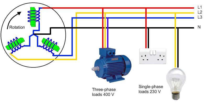
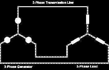
19 3 phase The power plant produces three different phases of AC power simultaneously, and the three phases are offset 120 degrees from each other. There are four wires coming out of every power plant the three phases plus a neutral or ground common to all three. If you were to look at the three phases on a graph, they would look like this relative to ground
20
21 3 phase

22 3 phase There is nothing magical about threephase power. It is simply three single phases synchronized and offset by 120 degrees
23 3 phase Three phase power transmission has become the standard for power distribution. Three phase power generation and distribution is advantageous over single phase power distribution.
24 3 phase Three phase power distribution requires lesser amounts of copper or aluminium for transferring the same amount of power as compared to single phase power
25 3 phase The size of a three phase motor is smaller than that of a single phase motor of the same rating. Three phase motors are self starting as they can produce a rotating magnetic field. The single phase motor requires a special starting winding as it produces only a pulsating magnetic field.
26 3 phase In single phase motors, the power transferred in motors is a function of the instantaneous current which is constantly varying. Hence, single phase motors are more prone to vibrations. In three phase motors, however, the power transferred is uniform through out the cycle and hence vibrations are greatly reduced.
27 3 phase The ripple factor of rectified DC produced from three phase power is less than the DC produced from single phase supply. Three phase motors have better power factor regulation. Motors above 10HP are usually three phase. Three phase generators are smaller in size than single phase generators as winding phase can be more efficiently used.
28 3 phase
29 Star or Y configuration Line voltage = 3 x Phase voltage L1 Phase voltage L2 Phase current = Line current L line = I phase L3 Neutral (optional)
30 3 phase Line voltage refers to the amount of voltage measured between any two line conductors in a balanced three-phase system. With the above circuit, the line voltage is roughly 208 volts. Phase voltage refers to the voltage measured across any one component (source winding or load impedance) in a balanced three-phase source or load. For the circuit shown above, the phase voltage is 120 volts
31 Delta configuration Line voltage = phase voltage L1 Line current = 3 x phase current L2 I line = 3 x I phase L3
32 3 phase If line values of voltage and current are known, the power (watts) of a pure resistive load can be computed using the formula: Total Power = 3 E line X I Line

33 Direction of rotation in 3 phase generator
34 30 o X V The line voltage, the resultant (green arrow) of the phase voltages can be found using the sine rule XV/sin 120 o = 120V/sin 30 o = 208 V 120V 120 o 120V 30 o
35 30 o Phase voltage is line voltage 3 i.e a line voltage of 433 volts has a phase voltage of 250 Volts X V 120V 120 o 120V 30 o
36 Transformers Transformers step up or step down AC voltage depending on the ratio of primary and secondary windings V s /V p = N s /N p
37 Transformers
38 Other transformer/ inductor equations The AC current in the primary coil induces and changing magnetic in the core. The magneto motive force of the coil F if found by the equation F = NI (amp- turns) where N is the number of turns of wire in the coil and I is the current in the wire. the magnetic field strength H is the mmf per unit length ( L) of the coil. H = F L (amp-turns)/m Flux density (B) is closely related to field strength and is flux area unit Tesla (T)
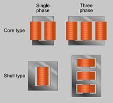
39 Shell transformers


40 Core and shell type transformers Magnetic flux Magnetic flux In the shell type transformer the magnetic flux in the side limbs is half the flux in the centre limb
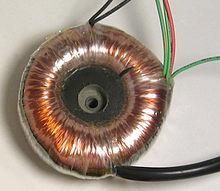
41 toroidal

42 C core
43 efficiency Normally when we do transformer calculations we assume 100% efficiency. In reality this is not the case Energy can be lost as heat in the coils and the core
44 efficiency This can be calculated as % regulation (V in V out ) x 100/V in % Efficiency = (power out power in ) x 100 ((V x I) out ) ((V x I ) in ) x 100
45 efficiency A power transformer operates from the 240V 50Hz ac mains; it supplies a purely resistive heating load at 110 V. The secondary current is 30 A and the primary current is 15A. When the load is disconnected, the secondary voltage rises to 120 V. Calculate: a) Power supplied from the ac mains b) % regulation c) Transformer efficiency d) Transformer losses e) State TWO reasons for the losses in d)
46 efficiency Answers a) Power supplied from the ac mains 240 x 15 = 3600W b) % regulation ( ) x = 8.3% c) Transformer efficiency (110 x 30) x = 91.6% d) Transformer losses 3600W 3300 W =300W e) State TWO reasons for the losses in d) losses in the winding and losses in the core Core losses are minimised by using a laminated core

47 Other solenoid applications. Relay switch to enable a small circuit to switch on a large circuit
48 Other solenoid applications. When the relay is switched on the core of the solenoid is magnetised by a DC current supply. This attracts the lever closing the switch and activating the large circuit. When the relay is switched off the current in the relay coil stops flowing. This sudden change in current could induce a back emf in the circuit This can be prevented by putting a diode in the circuit

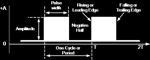
49 Square waves

50 Square waves
51 Square wave Duty cycle the percentage of time that the signal spends in an active state as a fraction of the total time under consideration 0 20% duty cycle 20% duty cycle 50% duty cycle 90% duty cycle
52 rms (Root Mean squared) Rms for a sign wave = peak 2 rms for a square wave = peak

53 Time constant Time taken for 63% of charge to take place
54 The time constant of a series RL circuit equal to the value of inductance divided by the resistance: T = L / R The time constant of a series RL circuit equal to the value of inductance divided by the resistance: T = L / R The time constant of a series RC circuit equal to the value of capacitance multiplied by the resistance T = CR
55 Wave period Time period for one wave is 1 frequency 50 Hz = 0.02 seconds
56 The Differentiator: The differentiator circuit performs the mathematical operation of differentiation. That is the output waveform is the derivative of the input waveform. V R C out F 1 dv dt in
57 The Integrator: A circuit in which the output voltage waveform is the integration of the input is called integrator
58 Differentiation & integration of sine waves The sine / cosine functions differentiate using standard sets of rules: d/dt(sin t) = cos t The differentiation of a sine wave is a cosine wave The integration of a sine wave is a cosine wave
59 Differentiation sine to cosine wave
60 Integration sine to cosine wave
Electrical Theory. Power Principles and Phase Angle. PJM State & Member Training Dept. PJM /22/2018
 Electrical Theory Power Principles and Phase Angle PJM State & Member Training Dept. PJM 2018 Objectives At the end of this presentation the learner will be able to: Identify the characteristics of Sine
SECTION 3 BASIC AUTOMATIC CONTROLS UNIT 12 BASIC ELECTRICITY AND MAGNETISM. Unit Objectives. Unit Objectives 2/29/2012
 SECTION 3 BASIC AUTOMATIC CONTROLS UNIT 12 BASIC ELECTRICITY AND MAGNETISM Unit Objectives Describe the structure of an atom. Identify atoms with a positive charge and atoms with a negative charge. Explain
ELECTROMAGNETIC INDUCTION AND ALTERNATING CURRENT (Assignment)
") ELECTROMAGNETIC INDUCTION AND ALTERNATING CURRENT (Assignment) 1. In an A.C. circuit A ; the current leads the voltage by 30 0 and in circuit B, the current lags behind the voltage by 30 0. What is the
ELECTROMAGNETIC INDUCTION AND ALTERNATING CURRENT (Assignment) 1. In an A.C. circuit A ; the current leads the voltage by 30 0 and in circuit B, the current lags behind the voltage by 30 0. What is the
TRANSFORMER OPERATION
 Chapter 3 TRANSFORMER OPERATION 1 A transformer is a static device (no moving parts) used to transfer energy from one AC circuit to another. This transfer of energy may involve an increase or decrease
Review 6. unlike poles cause the magnets to attract. like poles cause the magnets to repel.
 Review 6 1. The two characteristics of all magnets are: they attract and hold Iron, and, if free to move, they will assume roughly a south - north position. 2. Lines of flux always leave the north pole
CHAPTER 2. Basic Concepts, Three-Phase Review, and Per Unit
 CHAPTER 2 Basic Concepts, Three-Phase Review, and Per Unit 1 AC power versus DC power DC system: - Power delivered to the load does not fluctuate. - If the transmission line is long power is lost in the
QUESTION BANK ETE (17331) CM/IF. Chapter1: DC Circuits
 CM/IF. Chapter1: DC Circuits") QUESTION BANK ETE (17331) CM/IF Chapter1: DC Circuits Q1. State & explain Ohms law. Also explain concept of series & parallel circuit with the help of diagram. 3M Q2. Find the value of resistor in fig.
QUESTION BANK ETE (17331) CM/IF Chapter1: DC Circuits Q1. State & explain Ohms law. Also explain concept of series & parallel circuit with the help of diagram. 3M Q2. Find the value of resistor in fig.
Contents. Core information about Unit
 1 Contents Core information about Unit UEENEEH114A - Troubleshoot resonance circuits......3 UEENEEG102A Solve problems in low voltage AC circuits...5 TextBook...7 Topics and material Week 1...9 2 Core
Generator Advanced Concepts
 Generator Advanced Concepts Common Topics, The Practical Side Machine Output Voltage Equation Pitch Harmonics Circulating Currents when Paralleling Reactances and Time Constants Three Generator Curves
UEE11 Electrotechnology. Training Package
 UEE11 Electrotechnology Training Package UEENEEJ153A Find and rectify faults in motors and associated controls in refrigeration and air conditioning systems Learner Workbook Version 1 Training and Education
ELECTRIC CURRENTS AND CIRCUITS By: Richard D. Beard P.E.
 ELECTRICAL POWER There are two types of electric power in use, direct current (dc) and alternating current (ac). The most common use of direct current is automotive, including storage batteries, starter
Electronics for Analog Signal Processing - I Prof. K. Radhakrishna Rao Department of Electrical Engineering Indian Institute of Technology - Madras
 Electronics for Analog Signal Processing - I Prof. K. Radhakrishna Rao Department of Electrical Engineering Indian Institute of Technology - Madras Lecture - 6 Full Wave Rectifier and Peak Detector In
3. What is hysteresis loss? Also mention a method to minimize the loss. (N-11, N-12)
") DHANALAKSHMI COLLEGE OF ENGINEERING, CHENNAI DEPARTMENT OF ELECTRICAL AND ELECTRONICS ENGINEERING EE 6401 ELECTRICAL MACHINES I UNIT I : MAGNETIC CIRCUITS AND MAGNETIC MATERIALS Part A (2 Marks) 1. List
DHANALAKSHMI COLLEGE OF ENGINEERING, CHENNAI DEPARTMENT OF ELECTRICAL AND ELECTRONICS ENGINEERING EE 6401 ELECTRICAL MACHINES I UNIT I : MAGNETIC CIRCUITS AND MAGNETIC MATERIALS Part A (2 Marks) 1. List
CHAPTER 5 CONCEPTS OF ALTERNATING CURRENT
 CHAPTER 5 CONCEPTS OF ALTERNATING CURRENT INTRODUCTION Thus far this text has dealt with direct current (DC); that is, current that does not change direction. However, a coil rotating in a magnetic field
Alternating Current Page 1 30
 Alternating Current 26201 11 Page 1 30 Calculate the peak and effective voltage of current values for AC Calculate the phase relationship between two AC waveforms Describe the voltage and current phase
ELG 4125: ELECTRICAL POWER TRANSMISSION AND DISTRIBUTION: TUTORIAL 1: - BY:
 ELG 4125: ELECTRICAL POWER TRANSMISSION AND DISTRIBUTION: TUTORIAL 1: - BY: Faizhussain Arsiwala POWER FACTOR: The cosine of angle between voltage and current in an a.c. circuit is known as power factor.
5.0 THREE PHASE SYSTEM
 5.0 THREE PHASE SYSTEM ET 201 BAKISS HIYANA BAU BAKAR JKE, POLISAS 1 COURSE LEARNING OUTCOME 1. Explain AC circuit concept and their analysis using AC circuit law. 2. Apply the knowledge of AC circuit
Chapter 33. Alternating Current Circuits
 Chapter 33 Alternating Current Circuits Alternating Current Circuits Electrical appliances in the house use alternating current (AC) circuits. If an AC source applies an alternating voltage to a series
11. AC-resistances of capacitor and inductors: Reactances.
 11. AC-resistances of capacitor and inductors: Reactances. Purpose: To study the behavior of the AC voltage signals across elements in a simple series connection of a resistor with an inductor and with
CHAPTER 6: ALTERNATING CURRENT
 CHAPTER 6: ALTERNATING CURRENT PSPM II 2005/2006 NO. 12(C) 12. (c) An ac generator with rms voltage 240 V is connected to a RC circuit. The rms current in the circuit is 1.5 A and leads the voltage by
Aligarh College of Engineering & Technology (College Code: 109) Affiliated to UPTU, Approved by AICTE Electrical Engg.
 Affiliated to UPTU, Approved by AICTE Electrical Engg.") Aligarh College of Engineering & Technology (College Code: 19) Electrical Engg. (EE-11/21) Unit-I DC Network Theory 1. Distinguish the following terms: (a) Active and passive elements (b) Linearity and
Aligarh College of Engineering & Technology (College Code: 19) Electrical Engg. (EE-11/21) Unit-I DC Network Theory 1. Distinguish the following terms: (a) Active and passive elements (b) Linearity and
Power Quality Monitoring and Power Metering Tutorial
 Power Quality Monitoring and Power Metering Tutorial Power generation and transmission today are accomplished using three phase alternatingcurrent. To understand electrical power quality monitoring and
Module 1. Introduction. Version 2 EE IIT, Kharagpur
 Module 1 Introduction Lesson 1 Introducing the Course on Basic Electrical Contents 1 Introducing the course (Lesson-1) 4 Introduction... 4 Module-1 Introduction... 4 Module-2 D.C. circuits.. 4 Module-3
SHRI RAMSWAROOP MEMORIAL COLLEGE OF ENGG. & MANAGEMENT B.Tech. [SEM I (EE, EN, EC, CE)] QUIZ TEST-3 (Session: ) Time: 1 Hour ELECTRICAL ENGINEE
![SHRI RAMSWAROOP MEMORIAL COLLEGE OF ENGG. & MANAGEMENT B.Tech. [SEM I (EE, EN, EC, CE)] QUIZ TEST-3 (Session: ) Time: 1 Hour ELECTRICAL ENGINEE](/thumbs/94/118213481.jpg "SHRI RAMSWAROOP MEMORIAL COLLEGE OF ENGG. & MANAGEMENT B.Tech. [SEM I (EE, EN, EC, CE)] QUIZ TEST-3 (Session: ) Time: 1 Hour ELECTRICAL ENGINEE") SHRI RAMSWAROOP MEMORIAL COLLEGE OF ENGG. & MANAGEMENT B.Tech. [SEM I (EE, EN, EC, CE)] QUIZ TEST-3 (Session: 2014-15) Time: 1 Hour ELECTRICAL ENGINEERING Max. Marks: 30 (NEE-101) Roll No. Academic/26
SHRI RAMSWAROOP MEMORIAL COLLEGE OF ENGG. & MANAGEMENT B.Tech. [SEM I (EE, EN, EC, CE)] QUIZ TEST-3 (Session: 2014-15) Time: 1 Hour ELECTRICAL ENGINEERING Max. Marks: 30 (NEE-101) Roll No. Academic/26
Chapter 7. Copyright The McGraw-Hill Companies, Inc. Permission required for reproduction or display.
 Chapter 7 Copyright The McGraw-Hill Companies, Inc. Permission required for reproduction or display. Learning Objectives 1. Understand the meaning of instantaneous and average power, master AC power notation,
Basic Electrical Training
 Basic Electrical Training Electricians Tools Explain how various hand tools are used by an electrician Discuss the safe use of hand tools and power tools Perform basic calculations and measurement conversions
Power Electrician Level 3
 s Power Electrician Level 3 Rev. September 2008 Power Electrician Unit: C1 Electrical Code III Level: Three Duration: 60 hours Theory: Practical: 60 hours 0 hours Overview: This unit of instruction is
Chapter 24. Alternating Current Circuits
 Chapter 24 Alternating Current Circuits Objective of Lecture Generators and Motors Inductance RL Circuits (resistance and inductance) Transformers AC REMINDER: WORK ON THE EXAMPLES Read physics in perspective
Inductance, capacitance and resistance
 Inductance, capacitance and resistance As previously discussed inductors and capacitors create loads on a circuit. This is called reactance. It varies depending on current and frequency. At no frequency,
AC Power Instructor Notes
 Chapter 7: AC Power Instructor Notes Chapter 7 surveys important aspects of electric power. Coverage of Chapter 7 can take place immediately following Chapter 4, or as part of a later course on energy
Construction Electrician Level 2
 Level 2 Rev. September 2008 Unit: B1 Electrical Code II Level: Two Duration: 120 hours Theory: Practical: 99 hours 21 hours Overview: This unit of instruction is designed to provide the Electrician apprentice
Chapter 11. Alternating Current
 Unit-2 ECE131 BEEE Chapter 11 Alternating Current Objectives After completing this chapter, you will be able to: Describe how an AC voltage is produced with an AC generator (alternator) Define alternation,
KINGS COLLEGE OF ENGINEERING DEPARTMENT OF ELECTRICAL AND ELECTRONICS ENGINEERING QUESTION BANK UNIT I BASIC CIRCUITS ANALYSIS PART A (2-MARKS)
") KINGS COLLEGE OF ENGINEERING DEPARTMENT OF ELECTRICAL AND ELECTRONICS ENGINEERING QUESTION BANK YEAR / SEM : I / II SUBJECT CODE & NAME : EE 1151 CIRCUIT THEORY UNIT I BASIC CIRCUITS ANALYSIS PART A (2-MARKS)
KINGS COLLEGE OF ENGINEERING DEPARTMENT OF ELECTRICAL AND ELECTRONICS ENGINEERING QUESTION BANK YEAR / SEM : I / II SUBJECT CODE & NAME : EE 1151 CIRCUIT THEORY UNIT I BASIC CIRCUITS ANALYSIS PART A (2-MARKS)
An induced emf is the negative of a changing magnetic field. Similarly, a self-induced emf would be found by
 This is a study guide for Exam 4. You are expected to understand and be able to answer mathematical questions on the following topics. Chapter 32 Self-Induction and Induction While a battery creates an
Question Paper Profile
 I Scheme Question Paper Profile Program Name : Electrical Engineering Program Group Program Code : EE/EP/EU Semester : Third Course Title : Electrical Circuits Max. Marks : 70 Time: 3 Hrs. Instructions:
INSTITUTE OF AERONAUTICAL ENGINEERING (AUTONOMOUS)
") Name Code Class Branch INSTITUTE OF AERONAUTICAL ENGINEERING (AUTONOMOUS) Dundigal, Hyderabad -500 043 CIVIL ENGINEERING TUTORIAL QUESTION BANK : ELECTRICAL AND ELECTRONICS ENGINEERING : A30203 : II B.
Name Code Class Branch INSTITUTE OF AERONAUTICAL ENGINEERING (AUTONOMOUS) Dundigal, Hyderabad -500 043 CIVIL ENGINEERING TUTORIAL QUESTION BANK : ELECTRICAL AND ELECTRONICS ENGINEERING : A30203 : II B.
Radar. Radio. Electronics. Television. .104f 4E011 UNITED ELECTRONICS LABORATORIES LOUISVILLE
 Electronics Radio Television.104f Radar UNITED ELECTRONICS LABORATORIES LOUISVILLE KENTUCKY REVISED 1967 4E011 1:1111E111611 COPYRIGHT 1956 UNITED ELECTRONICS LABORATORIES POWER SUPPLIES ASSIGNMENT 23
Unit 3 Magnetism...21 Introduction The Natural Magnet Magnetic Polarities Magnetic Compass...21
 Chapter 1 Electrical Fundamentals Unit 1 Matter...3 Introduction...3 1.1 Matter...3 1.2 Atomic Theory...3 1.3 Law of Electrical Charges...4 1.4 Law of Atomic Charges...4 Negative Atomic Charge...4 Positive
INSTITUTE OF AERONAUTICAL ENGINEERING Dundigal, Hyderabad
 Course Name Course Code Class Branch INSTITUTE OF AERONAUTICAL ENGINEERING Dundigal, Hyderabad -500 043 AERONAUTICAL ENGINEERING TUTORIAL QUESTION BANK : ELECTRICAL AND ELECTRONICS ENGINEERING : A40203
1. A battery has an emf of 12.9 volts and supplies a current of 3.5 A. What is the resistance of the circuit?
 1. A battery has an emf of 12.9 volts and supplies a current of 3.5 A. What is the resistance of the circuit? (a) 3.5 Ω (b) 16.4 Ω (c) 3.69 Ω (d) 45.15 Ω 2. Sign convention used for potential is: (a) Rise
Preface...x Chapter 1 Electrical Fundamentals
 Preface...x Chapter 1 Electrical Fundamentals Unit 1 Matter...3 Introduction...3 1.1 Matter...3 1.2 Atomic Theory...3 1.3 Law of Electrical Charges...4 1.4 Law of Atomic Charges...5 Negative Atomic Charge...5
+ 24V 3.3K - 1.5M. figure 01
 ELECTRICITY ASSESSMENT 35 questions Revised: 08 Jul 2013 1. Which of the wire sizes listed below results in the least voltage drop in a circuit carrying 10 amps: a. 16 AWG b. 14 AWG c. 18 AWG d. 250 kcmil
AUTO-TRANSFORMER. This is having only one winding; part of this winding is common to both primary and secondary.
 AUTO-TRANSFORMER This is having only one winding; part of this winding is common to both primary and secondary. In 2-winding transformer both primary and secondary windings are electrically isolated, but
Table of Contents. Introduction...2 Conductors and Insulators...3 Current, Voltage, and Resistance...6
 Table of Contents Introduction...2 Conductors and Insulators...3 Current, Voltage, and Resistance...6 Ohm s Law... 11 DC Circuits... 13 Magnetism...20 Alternating Current...23 Inductance and Capacitance...30
Electricity Basics
 Western Technical College 31660310 Electricity Basics Course Outcome Summary Course Information Description Career Cluster Instructional Level Total Credits 4.00 Total Hours 144.00 DC/AC electrical theory
UNIVERSITY OF TECHNOLOGY By: Fadhil A. Hasan ELECTRICAL MACHINES
 UNIVERSITY OF TECHNOLOGY DEPARTMENT OF ELECTRICAL ENGINEERING Year: Second 2016-2017 By: Fadhil A. Hasan ELECTRICAL MACHINES І Module-II: AC Transformers o Single phase transformers o Three-phase transformers
Experiment 45. Three-Phase Circuits. G 1. a. Using your Power Supply and AC Voltmeter connect the circuit shown OBJECTIVE
 Experiment 45 Three-Phase Circuits OBJECTIVE To study the relationship between voltage and current in three-phase circuits. To learn how to make delta and wye connections. To calculate the power in three-phase
Bakiss Hiyana binti Abu Bakar JKE, POLISAS BHAB
 1 Bakiss Hiyana binti Abu Bakar JKE, POLISAS 1. Explain AC circuit concept and their analysis using AC circuit law. 2. Apply the knowledge of AC circuit in solving problem related to AC electrical circuit.
Electrical Machines I : Transformers
 UNIT TRANSFORMERS PART A (Q&A) 1. What is step down transformer? The transformer used to step down the voltage from primary to secondary is called as step down transformer. (Ex: /11).. Draw the noload
Alternating Current. Slide 1 / 69. Slide 2 / 69. Slide 3 / 69. Topics to be covered. Sources of Alternating EMF. Sources of alternating EMF
 Slide 1 / 69 lternating urrent Sources of alternating EMF Transformers ircuits and Impedance Topics to be covered Slide 2 / 69 LR Series ircuits Resonance in ircuit Oscillations Sources of lternating EMF
Alternating Current. Slide 2 / 69. Slide 1 / 69. Slide 3 / 69. Slide 4 / 69. Slide 6 / 69. Slide 5 / 69. Topics to be covered
 Slide 1 / 69 lternating urrent Sources of alternating EMF ircuits and Impedance Slide 2 / 69 Topics to be covered LR Series ircuits Resonance in ircuit Oscillations Slide 3 / 69 Sources of lternating EMF
2.0 AC CIRCUITS 2.1 AC VOLTAGE AND CURRENT CALCULATIONS. ECE 4501 Power Systems Laboratory Manual Rev OBJECTIVE
 2.0 AC CIRCUITS 2.1 AC VOLTAGE AND CURRENT CALCULATIONS 2.1.1 OBJECTIVE To study sinusoidal voltages and currents in order to understand frequency, period, effective value, instantaneous power and average
SIDDHARTH GROUP OF INSTITUTIONS :: PUTTUR (AUTONOMOUS) Siddharth Nagar, Narayanavanam Road QUESTION BANK (DESCRIPTIVE) UNIT I INTRODUCTION
 Siddharth Nagar, Narayanavanam Road QUESTION BANK (DESCRIPTIVE) UNIT I INTRODUCTION") SIDDHARTH GROUP OF INSTITUTIONS :: PUTTUR (AUTONOMOUS) Siddharth Nagar, Narayanavanam Road 517583 QUESTION BANK (DESCRIPTIVE) Subject with Code : Electrical Circuits(16EE201) Year & Sem: I-B.Tech & II-Sem
SIDDHARTH GROUP OF INSTITUTIONS :: PUTTUR (AUTONOMOUS) Siddharth Nagar, Narayanavanam Road 517583 QUESTION BANK (DESCRIPTIVE) Subject with Code : Electrical Circuits(16EE201) Year & Sem: I-B.Tech & II-Sem
Principle Of Step-up Chopper
 Principle Of Step-up Chopper L + D + V Chopper C L O A D V O 1 Step-up chopper is used to obtain a load voltage higher than the input voltage V. The values of L and C are chosen depending upon the requirement
3.1.Introduction. Synchronous Machines
 3.1.Introduction Synchronous Machines A synchronous machine is an ac rotating machine whose speed under steady state condition is proportional to the frequency of the current in its armature. The magnetic
CHAPTER THREE PHASE SYSTEM (3 Φ ) C h a p t e r 3 71
 C h a p t e r 3 71") C h a p t e r 3 71 CHATE 3 THEE HASE SSTEM (3 Φ ) 3.0 NTODUCTON This chapter is explaining about the three phase system. The learning outcome is student should be able to apply the principles of three
C h a p t e r 3 71 CHATE 3 THEE HASE SSTEM (3 Φ ) 3.0 NTODUCTON This chapter is explaining about the three phase system. The learning outcome is student should be able to apply the principles of three
ALTERNATING CURRENT. Lesson-1. Alternating Current and Voltage
 esson- ATENATING UENT Alternating urrent and oltage An alternating current or voltage is that variation of current or voltage respectively whose magnitude and direction vary periodically and continuously
INSTITUTE OF AERONAUTICAL ENGINEERING (Autonomous) Dundigal, Hyderabad
 Dundigal, Hyderabad") I INSTITUTE OF AERONAUTICAL ENGINEERING (Autonomous) Dundigal, Hyderabad-500043 CIVIL ENGINEERING TUTORIAL QUESTION BANK Course Name : BASIC ELECTRICAL AND ELECTRONICS ENGINEERING Course Code : AEE018
I INSTITUTE OF AERONAUTICAL ENGINEERING (Autonomous) Dundigal, Hyderabad-500043 CIVIL ENGINEERING TUTORIAL QUESTION BANK Course Name : BASIC ELECTRICAL AND ELECTRONICS ENGINEERING Course Code : AEE018
CHAPTER 2. Transformers. Dr Gamal Sowilam
 CHAPTER Transformers Dr Gamal Sowilam Introduction A transformer is a static machine. It is not an energy conversion device, it is indispensable in many energy conversion systems. A transformer essentially
Chapter Moving Charges and Magnetism
 100 Chapter Moving Charges and Magnetism 1. The power factor of an AC circuit having resistance (R) and inductance (L) connected in series and an angular velocity ω is [2013] 2. [2002] zero RvB vbl/r vbl
Downloaded From All JNTU World
 Code: 9A02403 GENERATION OF ELECTRIC POWER 1 Discuss the advantages and disadvantages of a nuclear plant as compared to other conventional power plants. 2 Explain about: (a) Solar distillation. (b) Solar
ECE 2006 University of Minnesota Duluth Lab 11. AC Circuits
 1. Objective AC Circuits In this lab, the student will study sinusoidal voltages and currents in order to understand frequency, period, effective value, instantaneous power and average power. Also, the
PHYSICS WORKSHEET CLASS : XII. Topic: Alternating current
 PHYSICS WORKSHEET CLASS : XII Topic: Alternating current 1. What is mean by root mean square value of alternating current? 2. Distinguish between the terms effective value and peak value of an alternating
MAHARASHTRA STATE BOARD OF TECHNICAL EDUCATION
 Important Instructions to examiners: 1. The answers should be examined by key words and not as word-to-word as given in the model answer scheme. 2. The model answer and the answer written by candidate
INSTITUTE OF AERONAUTICAL ENGINEERING (AUTONOMOUS) Dundigal, Hyderabad
 Dundigal, Hyderabad") INSTITUTE OF AERONAUTICAL ENGINEERING (AUTONOMOUS) Dundigal, Hyderabad - 500 043 CIVIL ENGINEERING ASSIGNMENT Name : Electrical and Electronics Engineering Code : A30203 Class : II B. Tech I Semester Branch
INSTITUTE OF AERONAUTICAL ENGINEERING (AUTONOMOUS) Dundigal, Hyderabad - 500 043 CIVIL ENGINEERING ASSIGNMENT Name : Electrical and Electronics Engineering Code : A30203 Class : II B. Tech I Semester Branch
ET1210: Module 5 Inductance and Resonance
 Part 1 Inductors Theory: When current flows through a coil of wire, a magnetic field is created around the wire. This electromagnetic field accompanies any moving electric charge and is proportional to
Direct Current Waveforms
 Cornerstone Electronics Technology and Robotics I Week 20 DC and AC Administration: o Prayer o Turn in quiz Direct Current (dc): o Direct current moves in only one direction in a circuit. o Though dc must
Transformers 1 of 25 Boardworks Ltd 2016
 Transformers 1 of 25 Boardworks Ltd 2016 Transformers 2 of 25 Boardworks Ltd 2016 Linking circuits with magnetism 3 of 25 Boardworks Ltd 2016 Transformers 4 of 25 Boardworks Ltd 2016 Power can be transferred
Electrical Engineering / Electromagnetics
 Electrical Engineering / Electromagnetics. Plot voltage versus time and current versus time for the circuit with the following substitutions: A. esistor B. Capacitor C. Inductor t = 0 A/B/C A. I t t B.
Unit 27 Three-Phase Circuits
 Unit 27 Three-Phase Circuits Objectives: Discuss the differences between threephase and single-phase voltages. Discuss the characteristics of delta and wye connections. Compute voltage and current values
DESIGN AND CONSTRUCTION OF 1500VA VARIABLE OUTPUT STEP DOWN TRANSFORMER
 DESIGN AND CONSTRUCTION OF 1500VA VARIABLE OUTPUT STEP DOWN TRANSFORMER OGUNDARE AYOADE B., OMOGOYE O. SAMUEL & OLUWASANYA OMOTAYO J. Department of Electrical/Electronic engineering, Lagos State Polytechnic,
CHIEF ENGINEER REG III/2 MARINE ELECTROTECHNOLOGY
 CHIEF ENGINEER REG III/2 MARINE ELECTROTECHNOLOGY LIST OF TOPICS 1 Electric Circuit Principles 2 Electronic Circuit Principles 3 Generation 4 Distribution 5 Utilisation The expected learning outcome is
Trade of Electrician. Introduction to AC
 Trade of Electrician Standards Based Apprenticeship Introduction to AC Phase 2 Module No. 2.1 Unit No. 2.1.9 COURSE NOTES Created by Gerry Ryan - Galway TC Revision 1. April 2000 by Gerry Ryan - Galway
Practical Tricks with Transformers. Larry Weinstein K0NA
 Practical Tricks with Transformers Larry Weinstein K0NA Practical Tricks with Transformers Quick review of inductance and magnetics Switching inductive loads How many voltages can we get out of a $10 Home
Reg. No. : BASIC ELECTRICAL TECHNOLOGY (ELE 101)
") Department of Electrical and Electronics Engineering Reg. No. : MNIPL INSTITUTE OF TECHNOLOGY, MNIPL ( Constituent Institute of Manipal University, Manipal) FIRST SEMESTER B.E. DEGREE MKEUP EXMINTION (REVISED
Department of Electrical and Electronics Engineering Reg. No. : MNIPL INSTITUTE OF TECHNOLOGY, MNIPL ( Constituent Institute of Manipal University, Manipal) FIRST SEMESTER B.E. DEGREE MKEUP EXMINTION (REVISED
Theory. Week. Lecture Day. TOPICS Week TOPICS. Intoduction Overview of DC Circuits. 1.use of measuring instruments-multimeter,cro etc.
 Name of faculty: Sanjay Puri Discipline: Applied Science (Electronics and Communication Engg.) Subject: Fundamentals of Electrical and Electronics Engg. Lesson Plan Duration: 36 weeks (From August 2018
A 11/89. Instruction Manual and Experiment Guide for the PASCO scientific Model SF-8616 and 8617 COILS SET. Copyright November 1989 $15.
 Instruction Manual and Experiment Guide for the PASCO scientific Model SF-8616 and 8617 012-03800A 11/89 COILS SET Copyright November 1989 $15.00 How to Use This Manual The best way to learn to use the
Electrical Theory 2 Lessons for Fall Semester:
 Electrical Theory 2 Lessons for Fall Semester: Lesson 1 Magnetism Lesson 2 Introduction to AC Theory Lesson 3 Lesson 4 Capacitance and Capacitive Reactance Lesson 5 Impedance and AC Circuits Lesson 6 AC
Outcomes of Harmonics & Its Reduction Techniques: A Comprehensive Review
 Outcomes of Harmonics & Its Reduction Techniques: A Comprehensive Review 1 Suvas M. Vora, 2 Dipak H. Bhatt, 3 Hardik Raval 1,2 P.G Student (Power System), 3 Assistant Professor Electrical engineering Dept,
15. the power factor of an a.c circuit is.5 what will be the phase difference between voltage and current in this
 1 1. In a series LCR circuit the voltage across inductor, a capacitor and a resistor are 30 V, 30 V and 60 V respectively. What is the phase difference between applied voltage and current in the circuit?
BEST BMET CBET STUDY GUIDE MODULE ONE
 BEST BMET CBET STUDY GUIDE MODULE ONE 1 OCTOBER, 2008 1. The phase relation for pure capacitance is a. current leads voltage by 90 degrees b. current leads voltage by 180 degrees c. current lags voltage
By Gill ( ) PDF created with FinePrint pdffactory trial version
 PDF created with FinePrint pdffactory trial version") By Gill (www.angelfire.com/al4/gill ) 1 Introduction One of the main reasons of adopting a.c. system instead of d.c. for generation, transmission and distribution of electrical power is that alternatin
By Gill (www.angelfire.com/al4/gill ) 1 Introduction One of the main reasons of adopting a.c. system instead of d.c. for generation, transmission and distribution of electrical power is that alternatin
EE 42/100 Lecture 16: Inductance. Rev B 3/15/2010 (8:55 PM) Prof. Ali M. Niknejad
 Prof. Ali M. Niknejad") A. M. Niknejad University of California, Berkeley EE 100 / 42 Lecture 16 p. 1/23 EE 42/100 Lecture 16: Inductance ELECTRONICS Rev B 3/15/2010 (8:55 PM) Prof. Ali M. Niknejad University of California, Berkeley
A. M. Niknejad University of California, Berkeley EE 100 / 42 Lecture 16 p. 1/23 EE 42/100 Lecture 16: Inductance ELECTRONICS Rev B 3/15/2010 (8:55 PM) Prof. Ali M. Niknejad University of California, Berkeley
ENGINEERING ACADEMY X V
 1. Two incandescent bulbs of rating 230, 100 W and 230, 500 W are connected in parallel across the mains. As a result, what will happen? a) 100 W bulb will glow brighter b) 500 W bulb will glow brighter
Power Measurements for Switch-Mode Power Supplies SAVE Verona 2011
 Power Measurements for Switch-Mode Power Supplies SAVE Verona 2011 Agenda Power measurements tools Switch-mode power supplies Automated power measurements Summary Reference information 2 Switch-Mode Power
CHAPTER 3 IMPROVEMENT OF LOAD POWER FACTOR USING FACTS CONTROLLERS
 40 CHAPTER 3 IMPROVEMENT OF LOAD POWER FACTOR USING FACTS CONTROLLERS 3.1 INTRODUCTION The low power factor effects on transmission line, switchgear, transformers etc. It is observed that if the power
Electrical Motor Power Measurement & Analysis
 Electrical Motor Power Measurement & Analysis Understand the basics to drive greater efficiency Test&Measurement Energy is one of the highest cost items in a plant or facility, and motors often consume
ELECTRONICS AND ELECTRICITY
 INTRODUCTION ELECTRONICS ND ELECTRICITY The science of Electronics and Electricity makes a very important contribution to our everyday existence. Electricity is concerned with the generation, transmission
Paper number: Principles of electrical and electronics technology Paper series: December Practice
 Paper number: 850-56 Paper series: December 04 Question Syllabus reference Question 0.0 a) i) Tesla. ii) Newton. iii) Henry. Marks mark each 4 0.0 0.0 0.0 i) Megavolt ii) Microvolt. a) Directly Inversely
EEE3441 Electrical Machines Department of Electrical Engineering. Lecture. Basic Operating Principles of Transformers
 Department of Electrical Engineering Lecture Basic Operating Principles of Transformers In this Lecture Basic operating principles of following transformers are introduced Single-phase Transformers Three-phase
Walchand Institute of Technology. Basic Electrical and Electronics Engineering. Transformer
 Walchand Institute of Technology Basic Electrical and Electronics Engineering Transformer 1. What is transformer? explain working principle of transformer. Electrical power transformer is a static device
APPLICATION NOTE - 018
 APPLICATION NOTE - 018 Power Transformers Background Power Transformers are used within an AC power distribution systems to increase or decrease the operating voltage to achieve the optimum transmission
Inductance in DC Circuits
 Inductance in DC Circuits Anurag Srivastava Concept: Inductance is characterized by the behavior of a coil of wire in resisting any change of electric current through the coil. Arising from Faraday's law,
Basics of Electricity
 Basics of Electricity A quickstep Online Course Siemens industry, Inc. www.usa.siemens.com/step Trademarks Siemens is a trademark of Siemens AG. Product names mentioned may be trademarks or registered
A Practical Guide to Free Energy Devices
 A Practical Guide to Free Energy Devices Part PatD14: Last updated: 25th February 2006 Author: Patrick J. Kelly This patent application shows the details of a device which it is claimed, can produce sufficient
Inductor and Transformer Design
 Inductor and Transformer Design 1 Introduction The conditioning of power flow in Power Electronic Systems (PES) is done through the use of electromagnetic elements (inductors and transformers). In this
INTRODUCTION...xiii Author s Comments...xiii Exam Preparation...xiii Difficult Concepts...xiv Textbook Errors and Corrections...xv Internet...
 INTRODUCTION...xiii Author s Comments...xiii Exam Preparation...xiii Difficult Concepts...xiv Textbook Errors and Corrections...xv Internet...xv UNIT 1 ELECTRICIAN S MATH AND BASIC ELECTRICAL FORMULAS...1
Chapter 13. Electric Circuits
 Chapter 13 Electric Circuits Lower Potential Battery (EMF - E) - + Higher Potential Bulb (Resistor) Wires (No Change in Potential) EMF (Voltage Source) _ + Resistor Working Circuits For a circuit to work,
Exercises of resistors 1. Calculate the resistance of a 10 m long Copper wire with diameter d = 1.0 mm.
 Exercises of resistors 1. Calculate the resistance of a 10 m long Copper wire with diameter d = 1.0 mm. 2. Calculate the resistances of following equipment: using 220V AC a) a 1000 W electric heater b)
Look over Chapter 31 sections 1-4, 6, 8, 9, 10, 11 Examples 1-8. Look over Chapter 21 sections Examples PHYS 2212 PHYS 1112
 PHYS 2212 Look over Chapter 31 sections 1-4, 6, 8, 9, 10, 11 Examples 1-8 PHYS 1112 Look over Chapter 21 sections 11-14 Examples 16-18 Good Things To Know 1) How AC generators work. 2) How to find the