Passive Component Analysis. OMICRON Lab Webinar Nov. 2015
|
|
|
- Jason Lenard Andrews
- 6 years ago
- Views:
Transcription
1 Passive Component Analysis OMICRON Lab Webinar Nov. 2015

2 Webinar Hints Activate the chat function Please mute your microphones to avoid echoes Feel free to post questions anytime using the chat function Please post your questions to Bernhard Baumgartner We will record the presentation such that you can view it again later Please mute yourself by clicking on this icon! Send questions via chat to Bernhard Baumgartner Page 2

3 Agenda Why do we analyze passive components How to measure component impedance A detailed look at a capacitor Inductor and transformer Filter simulation vs. real world Summary Page 3
4 Passive Components Essential parts in analog circuits Inductor and capacitor used e.g. to store energy or to create filter circuits Inductor: v t = L di t dt X L = ωl V I = Z L = jωl Capacitor: i t = C dv t dt X C = 1 ωc V I = Z C = 1 jωc Page 4


5 Theory and Reality Theoretically inductor and capacitor are purely reactive elements No resistive behavior and therefore lossless In reality parasitics can strongly influence the real behavior especially at higher frequencies Examples: Inductor: Wire has resistance Windings form electric field Core is not lossless Capacitor: Plates are resistive Rolling of foils creates inductance Insulator not lossless Page 5
6 TR2/H Equivalent Circuits Are used to model the real behavior of the components Different complexity of models 1 st order models are valid for one frequency Single Frequency Mode in BAS calculates R, L and C Frequency Sweep Mode calculates R, L and C over frequency 10 10n 8 8n TR1/Ohm n 4n 2n 0 0 5M 10M 15M 20M 25M 30M 35M 40M f/hz TR1: Rs(Impedance) TR2: Ls(Impedance) Page 6

7 Equivalent Circuits Higher complexity models are valid for a frequency range 2 nd Order equivalent circuits for inductor and capacitor 3 rd Order models (e.g. quartz crystal or piezo element) see Application Note: Equivalent Circuit Analysis of Quartz Crystals Parameter identification requires manual work or e.g. curve-fitting procedure Page 7
8 Bode 100 Impedance Measurement Methods Direct Measurements One-Port Reflection Impedance Adapter (3-port technique) External bridge (e.g. high impedance bridge) Indirect Measurements (via Gain) Shunt-Thru (2-port technique) Series-Thru (2-port technique) Voltage-Current Gain (3-port technique) Page 8


9 Direct Measurement Methods One-Port Impedance Adapter Recommended for 0.5 Ω - 10 kω Recommended for 20 mω kω External Bridge / Coupler Range depends on bridge Page 9


10 Indirect Measurement Methods Shunt-Thru S 21 Z DUT = 25Ω 1 S 21 Series-Thru Z DUT = 100 Ω 1 S 21 S 21 Recommended for 1 mω - 10 Ω Recommended for 1 kω < 10 MΩ Voltage Current Gain Gain = V CH2 V CH1 = V I = Z DUT Page 10


11 Impedance Range Overview Page 11


12 Why is it important to measure capacitors? A capacitor is NEVER just a capacitor Capacitor ESR influences the phase margin of power supplies Capacitor ESR influences the output ripple at the switching frequency of a SMPS ESR can change over Frequency Capacitors are inductors above their resonance frequency Page 12
 ESR = tan δ ωc = 0.")
13 What does the data sheet tell us? 220 µf aluminum capacitor C = 220µF (± 20%) ESR = tan δ ωc = π 120Hz 220µF = Hz Page 13
 f/hz ESR 100 50 TR2/ 0-50 Phase -100 10 2 10 3 10 4 10 5 10 6 10 7 f/hz TR2: Phase(Impedance) Capacity Page")
14 This is what the measurement tells us TR1/Ohm Impedance f/hz TR1: Mag(Impedance) TR1/Ohm f/hz TR1/Ohm Cursor 1 120, ,077m TR1: Rs(Impedance) f/hz ESR TR2/ 0-50 Phase f/hz TR2: Phase(Impedance) Capacity Page 14
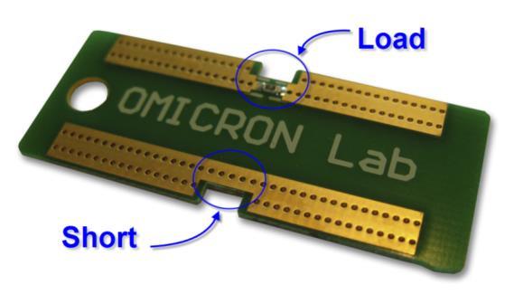
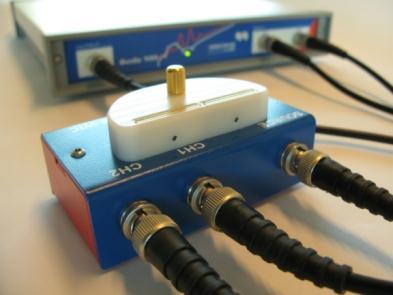
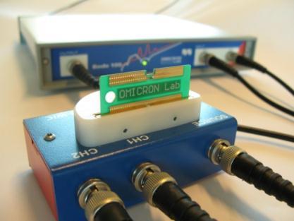
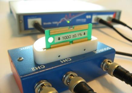
15 Calibration Open Short Load Page 15
")

")

16 User Calibration / Probe Calibration User Calibration (User Range Calibration) Calibrates at exactly the frequencies that are currently measured + No interpolation, suitable for narrowband probes Probe Calibration (Full Range Calibration) calibrates at pre-defined frequencies and interpolates in-between + Calibration does not get lost when frequency range is changed Page 16
 f/hz see Application Note: Capacitor ESR Measurement with Bode 100 and B-WIC https://www.omicron-lab.")
17 Detailed Example available TR2/F 5m 4m 3m 2m 1m 0-1m -2m -3m -4m -5m f/hz TR2: Cs(Impedance) 10 0 TR1/Ohm TR1: Rs(Impedance) f/hz see Application Note: Capacitor ESR Measurement with Bode 100 and B-WIC Page 17
18 Fitting Model to Measured Impedance Various methods available We use curve-fitting A Preview tool is available on request Page 18

19 TR2/ Simulation vs. Measurement TR1/Ohm TR1: Mag(Impedance) f/hz TR2: Phase(Impedance) Page 19


20 Voltage sensitivity of capacitors see Application Note: DC Biased Impedance Measurements Page 20
21 Why should we measure inductors? An inductor is NEVER just an inductor AC resistance <> DC resistance skin effects Eddie Currents Inductors have resonance frequencies Inductors with magnetic cores can have core losses Page 22

 R DC =0,057 Ω (max.")
22 What does the data sheet tell us? 33 µh shielded power inductor H = 33µH (± 1 khz R DC =0,049 Ω (typ.) R DC =0,057 Ω (max.) f res = 11 MHz Page 23
23 This is what the measurement tells us TR2/ TR1/Ohm f/hz TR1/Ohm 10 4 Cursor 1 13,362M 40,673k TR1: Mag(Impedance) 200 f/hz TR2/ 150 Cursor 1 13,362M -5, TR2: Phase(Impedance) f/hz f/hz Impedance Phase TR1/Ohm TR2/H f/hz TR1/Ohm 10 4 Cursor 1 292,486 40,049m Cursor 2 101,789k 759,543m 10 3 C2-C1 101,496k 719,494m u f/hz TR2/H Cursor 1 292,486 33,019µ Cursor 2 101,789k 30,551µ 200u C2-C1 101,496k -2,468µ 100u 0-100u TR1: Rs(Impedance) u TR2: Ls(Impedance) f/hz f/hz Inductance ESR Page 24
")
24 Flyback Transformer Leakage Inductance Not all flux generated by the primary winding is coupled to the secondary winding some flux leaks some contributes to core losses Represented by a series inductance in the circuit Leakage inductance creates a voltage spike when turning off current through primary side (flyback converter) Page 25
25 Measuring Leakage Inductance Leakage inductance is measured by shorting all other windings except the primary winding Secondary open Secondary shorted Leakage inductance TR1/Ohm TR2/H 12u 10u 8u 6u 4u 2u TR1: Mag(Impedance) f/hz Memory 1 : Mag(Impedance) TR2: Ls(Impedance) Leakage inductance is not constant over frequency f/hz Page 26
26 LC Filter Bode Diagram Simulation in LTSpice: Passband Resonance (Double-pole) Stopband -40dB/Decade -180 Phase Page 27


27 LC Filter Test board Measuring the voltage transfer function H jω = V out V in Page 28

28 Measurement vs. Simulation Measurement Simulation Stopband is different Phase does not reach -180 Second resonance at 30 MHz parasitic effects Page 29
 f/hz TR2: Phase(Gain) 180")

29 TR2/ LC Filter Including Parasitics TR1/dB TR1: Mag(Gain) f/hz TR2: Phase(Gain) much better fit between simulation and measurement Could be further improved by better component models Page 30
30 Reducing Output Ripple 2 x 10µF ceramics adds 20dB attenuation at 300 khz TR1/dB f/hz TR1/dB Cursor 1 290,070k -62,575 Imroved stop band performance at 300 khz (e.g. switching frequency) TR1: Mag(Gain) f/hz Memory 1 : Mag(Gain) Page 31

31 Summary Component parasitics are important to understand real life circuit behavior Models considering parasitics allow better simulation Measuring components can tell us more than the data sheet says Page 32
32 Feel free to ask questions via the chat function... If time runs out, please send us an and we will follow up. You can contact us at: Thank you for your attention!
Measuring Impedance with the Bode 100. OMICRON Lab Webinar Nov. 2014
 Measuring Impedance with the Bode 100 OMICRON Lab Webinar Nov. 2014 Let s start with a question Why do the presenters wear moustaches? http://moteam.co/omimobros Page 4 Agenda Direct Impedance measurement
Equivalent Circuit Determination of Quartz Crystals
 Page 1 of 11 Equivalent Circuit Determination of Quartz Crystals By Stephan Synkule & Florian Hämmerle 2010 Omicron Lab V1.1 Visit www.omicron-lab.com for more information. Contact support@omicron-lab.com
Invasive and Non-Invasive Stability Measurements
 Bode 1 - Application Note Page 1 of 22 Invasive and Non-Invasive Stability Measurements Using the Bode 1 and the Picotest J2111A Current Injector By Florian Hämmerle & Steve Sandler 211 Omicron Lab V1.1
Making Invasive and Non-Invasive Stability Measurements
 Making Invasive and Non-Invasive s Using the Bode 1 and the PICOTEST J2111A Current Injector By Florian Hämmerle & Steve Sandler 21 Picotest.com Visit www.picotest.com for more information. Contact support@picotest.com
Transformer modelling
 By Martin Bitschnau 2017 by OMICRON Lab V2.0 Visit www.omicron-lab.com for more information. Contact support@omicron-lab.com for technical support. Page 2 of 21 Table of Contents 1 EXECUTIVE SUMMARY...
DC Biased Impedance Measurement
 DC Biased Impedance Measurement Using the Bode 100 and the Picotest J2130A DC Bias Injector By Florian Hämmerle & Steve Sandler 2011 Picotest.com Visit www.picotest.com for more information. Contact support@picotest.com
Exclusive Technology Feature. An Accurate Method For Measuring Capacitor ESL. ISSUE: April by Steve Sandler, Picotest, Phoenix, Ariz.
 ISSUE: April 2011 An Accurate Method For Measuring Capacitor ESL by Steve Sandler, Picotest, Phoenix, Ariz. The equivalent series inductance (ESL) of chip capacitors is becoming an increasingly important
Power Supply Rejection Ratio Measurement
 Page 1 of 9 Measurement Using the Bode 100 and the J2120A Line Injector Voltage Regulator Contact us: +886-2-27053146 sales@telesplicing.com.tw Page 2 of 9 Table of Contents 1 Executive Summary...3 2 Measurement
DC/DC Converter Stability Measurement
 Strongly supported by By Stephan Synkule, Lukas Heinzle & Florian Hämmerle 214 by OMICRON Lab V2.1 Visit www.omicron-lab.com for more information. Contact support@omicron-lab.com for technical support.
Power Supply Rejection Ratio Measurement
 Power Supply Rejection Ratio Measurement Using the Bode 100 and the Picotest J2120A Line Injector By Florian Hämmerle & Steve Sandler 2010 Picotest.com Visit www.picotest.com for more information. Contact
Measure Low Value Impedance Current Shunt Impedance
 Measure Low Value Impedance Current Shunt Impedance By Florian Hämmerle 2017 Omicron Lab V2.0 Visit www.omicron-lab.com for more information. Contact support@omicron-lab.com for technical support. Page
DC/DC Converter Stability Measurement
 Bode 1 - Application Note Page 1 of 15 DC/DC Converter Stability Measurement Strongly supported by By Stephan Synkule, Lukas Heinzle & Florian Hämmerle 213 Omicron Lab V2. Visit www.omicron-lab.com for
Solar Cell Impedance Measurement using the Bode 100
 Page 1 of 9 Measurement using the Bode 100 By Florian Hämmerle 2011 Omicron Lab V1.0 Visit www.omicron-lab.com for more information. Contact support@omicron-lab.com for technical support. Page 2 of 9 Table
Low Value Impedance Measurement using the Voltage / Current Method
 Low Value Impedance Measurement using the Voltage / Current Method By Florian Hämmerle & Tobias Schuster 2017 Omicron Lab V2.2 Visit www.omicron-lab.com for more information. Contact support@omicron-lab.com
Measuring Power Line Impedance
 By Florian Hämmerle & Tobias Schuster 2017 by OMICRON Lab V1.1 Visit www.omicron-lab.com for more information. Contact support@omicron-lab.com for technical support. Page 2 of 13 Table of Contents 1 MEASUREMENT
S-Parameter Measurements with the Bode 100
 Page 1 of 10 with the Bode 100 Page 2 of 10 Table of Contents 1 S-Parameters...3 2 S-Parameter Measurement with the Bode 100...4 2.1 Device Setup...4 2.2 Calibration...5 2.3 Measurement...7 2.3.1 S11 and
Grundlagen der Impedanzmessung
 Grundlagen der Impedanzmessung presented by Michael Benzinger Application Engineer - RF & MW Agenda Impedance Measurement Basics Impedance Basics Impedance Dependency Factors Impedance Measurement Methods
Understanding and Optimizing Electromagnetic Compatibility in Switchmode Power Supplies
 Understanding and Optimizing Electromagnetic Compatibility in Switchmode Power Supplies 1 Definitions EMI = Electro Magnetic Interference EMC = Electro Magnetic Compatibility (No EMI) Three Components
Equivalent Circuit Determination of Quartz Crystals
 Equivalent Circuit Determination of Quartz Crystals By Stephan Synkule & Florian Hämmerle 2017 by OMICRON Lab V2.1 Visit www.omicron-lab.com for more information. Contact support@omicron-lab.com for technical
Contactless RFID Tag Measurements
 By Florian Hämmerle & Martin Bitschnau 2017 by OMICRON Lab V3.1 Visit www.omicron-lab.com for more information. Contact support@omicron-lab.com for technical support. Page 2 of 13 Table of Contents 1 Executive
Core Technology Group Application Note 1 AN-1
 Measuring the Impedance of Inductors and Transformers. John F. Iannuzzi Introduction In many cases it is necessary to characterize the impedance of inductors and transformers. For instance, power supply
Core Technology Group Application Note 6 AN-6
 Characterization of an RLC Low pass Filter John F. Iannuzzi Introduction Inductor-capacitor low pass filters are utilized in systems such as audio amplifiers, speaker crossover circuits and switching power
Battery Impedance Measurement
 Page 1 of 8 Using the Bode 100 and the Picotest J2111A Current Injector Page 2 of 8 Table of Contents 1 Executive Summary...3 2 Measurement Task...3 3 Measurement Setup & Results...4 3.1.1 Device Setup...5
Experiment 8 Frequency Response
 Experiment 8 Frequency Response W.T. Yeung, R.A. Cortina, and R.T. Howe UC Berkeley EE 105 Spring 2005 1.0 Objective This lab will introduce the student to frequency response of circuits. The student will
Filters And Waveform Shaping
 Physics 3330 Experiment #3 Fall 2001 Purpose Filters And Waveform Shaping The aim of this experiment is to study the frequency filtering properties of passive (R, C, and L) circuits for sine waves, and
Non-ideal Behavior of Electronic Components at High Frequencies and Associated Measurement Problems
 Nonideal Behavior of Electronic Components at High Frequencies and Associated Measurement Problems Matthew Beckler beck0778@umn.edu EE30 Lab Section 008 October 27, 2006 Abstract In the world of electronics,
DC/DC Converter Stability Measurement
 Strongly supported by By Stephan Synkule, Lukas Heinzle & Florian Hämmerle 2018 by OMICRON Lab V3.3 Visit www.omicron-lab.com for more information. Contact support@omicron-lab.com for technical support.
Bode 100. User Manual
 Bode 100 User Manual Bode 100 User Manual Article Number VESD0661 - Manual Version: Bode100.AE.3 OMICRON Lab 2008. All rights reserved. This User Manual is a publication of OMICRON electronics GmbH. This
Radio Frequency Electronics
 Radio Frequency Electronics Frederick Emmons Terman Transformers Masters degree from Stanford and Ph.D. from MIT Later a professor at Stanford His students include William Hewlett and David Packard Wrote
Audio Amplifier Frequency Response
 By Tobias Schuster 2017 by OMICRON Lab V2.0 Visit www.omicron-lab.com for more information. Contact support@omicron-lab.com for technical support. Page 2 of 20 Table of Contents 1 EXECUTIVE SUMMARY...
EXPERIMENT 8: LRC CIRCUITS
 EXPERIMENT 8: LRC CIRCUITS Equipment List S 1 BK Precision 4011 or 4011A 5 MHz Function Generator OS BK 2120B Dual Channel Oscilloscope V 1 BK 388B Multimeter L 1 Leeds & Northrup #1532 100 mh Inductor
Radio Frequency Electronics
 Radio Frequency Electronics Preliminaries II Guglielmo Giovanni Maria Marconi Thought off by many people as the inventor of radio Pioneer in long-distance radio communications Shared Nobel Prize in 1909
Measurement of the equivalent circuit of quartz crystals
 Measurement of the equivalent circuit of quartz crystals This application note shows how to measure the equivalent circuit of a quartz crystal with Bode 100. A.) Basics: An equivalent describtion of a
FREQUENCY RESPONSE AND PASSIVE FILTERS LABORATORY
 FREQUENCY RESPONSE AND PASSIVE FILTERS LABORATORY In this experiment we will analytically determine and measure the frequency response of networks containing resistors, AC source/sources, and energy storage
Physically-Based Distributed Models for Multi-Layer Ceramic Capacitors
 Physically-Based Distributed Models for Multi-Layer Ceramic Capacitors Charles R Sullivan and Yuqin Sun Thayer School of Engineering Dartmouth College http://power.thayer.dartmouth.edu/ Introduction Why
Department of Electrical and Computer Engineering Lab 6: Transformers
 ESE Electronics Laboratory A Department of Electrical and Computer Engineering 0 Lab 6: Transformers. Objectives ) Measure the frequency response of the transformer. ) Determine the input impedance of
EXPERIMENT 4: RC, RL and RD CIRCUITs
 EXPERIMENT 4: RC, RL and RD CIRCUITs Equipment List Resistor, one each of o 330 o 1k o 1.5k o 10k o 100k o 1000k 0.F Ceramic Capacitor 4700H Inductor LED and 1N4004 Diode. Introduction We have studied
Input Impedance Measurements for Stable Input-Filter Design
 for Stable Input-Filter Design 1000 Converter Input Impedance 100 10 1 0,1 Filter Output Impedance 0,01 10 100 1000 10000 100000 By Florian Hämmerle 2017 by OMICRON Lab V1.0 Visit www.omicron-lab.com for
Theory: The idea of this oscillator comes from the idea of positive feedback, which is described by Figure 6.1. Figure 6.1: Positive Feedback
 Name1 Name2 12/2/10 ESE 319 Lab 6: Colpitts Oscillator Introduction: This lab introduced the concept of feedback in combination with bipolar junction transistors. The goal of this lab was to first create
Lab 2: Linear and Nonlinear Circuit Elements and Networks
 OPTI 380B Intermediate Optics Laboratory Lab 2: Linear and Nonlinear Circuit Elements and Networks Objectives: Lean how to use: Function of an oscilloscope probe. Characterization of capacitors and inductors
INTRODUCTION TO AC FILTERS AND RESONANCE
 AC Filters & Resonance 167 Name Date Partners INTRODUCTION TO AC FILTERS AND RESONANCE OBJECTIVES To understand the design of capacitive and inductive filters To understand resonance in circuits driven
EE 221 L CIRCUIT II LABORATORY 4: AC CIRCUITS, CAPACITORS AND INDUCTORS UNIVERSITY OF NEVADA, LAS VEGAS OBJECTIVE COMPONENTS & EQUIPMENT BACKGROUND
 EE 221 L CIRCUIT II LABORATORY 4: AC CIRCUITS, CAPACITORS AND INDUCTORS DEPARTMENT OF ELECTRICAL AND COMPUTER ENGINEERING UNIVERSITY OF NEVADA, LAS VEGAS OBJECTIVE Compare the difference between DC and
Hidden schematics of EMI filters
 International Conference on Renewable Energies and Power Quality (ICREPQ 6) Madrid (Spain), 4 th to 6 th May, 26 exçxãtuäx XÇxÜzç tçw céãxü dâtä àç ]ÉâÜÇtÄ(RE&PQJ) ISSN 272-38 X, No.4 May 26 Hidden schematics
PHYS 3322 Modern Laboratory Methods I AC R, RC, and RL Circuits
 Purpose PHYS 3322 Modern Laboratory Methods I AC, C, and L Circuits For a given frequency, doubling of the applied voltage to resistors, capacitors, and inductors doubles the current. Hence, each of these
Experiment 18: Driven RLC Circuit
 MASSACHUSETTS INSTITUTE OF TECHNOLOGY Department of Physics 8. Spring 3 Experiment 8: Driven LC Circuit OBJECTIVES To measure the resonance frequency and the quality factor of a driven LC circuit INTODUCTION
Chapter 31 Alternating Current
 Chapter 31 Alternating Current In this chapter we will learn how resistors, inductors, and capacitors behave in circuits with sinusoidally vary voltages and currents. We will define the relationship between
Smart Measurement Solutions. Bode 100. User Manual
 Smart Measurement Solutions Bode 100 User Manual Bode 100 User Manual Bode 100 User Manual Article Number VESD0661 - Manual Version: Bode100.AE.4 OMICRON Lab 2010. All rights reserved. This User Manual
Electromagnetic Oscillations and Currents. March 23, 2014 Chapter 30 1
 Electromagnetic Oscillations and Currents March 23, 2014 Chapter 30 1 Driven LC Circuit! The voltage V can be thought of as the projection of the vertical axis of the phasor V m representing the time-varying
AC Circuits INTRODUCTION DISCUSSION OF PRINCIPLES. Resistance in an AC Circuit
 AC Circuits INTRODUCTION The study of alternating current 1 (AC) in physics is very important as it has practical applications in our daily lives. As the name implies, the current and voltage change directions
Chapter 33. Alternating Current Circuits
 Chapter 33 Alternating Current Circuits Alternating Current Circuits Electrical appliances in the house use alternating current (AC) circuits. If an AC source applies an alternating voltage to a series
Chapter 2-1 Transformers
 Principles of Electric Machines and Power Electronics Chapter 2-1 Transformers Third Edition P. C. Sen Transformer application 1: power transmission Ideal Transformer Assumptions: 1. Negligible winding
Power Supply Rejection Ratio Measurement
 Power Supply Rejection Ratio Measurement Using the Bode 100 and the Picotest J2120A Line Injector By Florian Hämmerle & Steve Sandler 2017 by OMICRON Lab V2.0 Visit www.omicron-lab.com for more information.
Chapter 2. The Fundamentals of Electronics: A Review
 Chapter 2 The Fundamentals of Electronics: A Review Topics Covered 2-1: Gain, Attenuation, and Decibels 2-2: Tuned Circuits 2-3: Filters 2-4: Fourier Theory 2-1: Gain, Attenuation, and Decibels Most circuits
TSTE25 Power Electronics. Lecture 6 Tomas Jonsson ISY/EKS
 TSTE25 Power Electronics Lecture 6 Tomas Jonsson ISY/EKS 2016-11-15 2 Outline DC power supplies DC-DC Converter Step-down (buck) Step-up (boost) Other converter topologies (overview) Exercises 7-1, 7-2,
Inductors & Resonance
 Inductors & Resonance The Inductor This figure shows a conductor carrying a current. A magnetic field is set up around the conductor as concentric circles. If a coil of wire has a current flowing through
6.334 Final Project Buck Converter
 Nathan Monroe monroe@mit.edu 4/6/13 6.334 Final Project Buck Converter Design Input Filter Filter Capacitor - 40µF x 0µF Capstick CS6 film capacitors in parallel Filter Inductor - 10.08µH RM10/I-3F3-A630
University of Jordan School of Engineering Electrical Engineering Department. EE 219 Electrical Circuits Lab
 University of Jordan School of Engineering Electrical Engineering Department EE 219 Electrical Circuits Lab EXPERIMENT 4 TRANSIENT ANALYSIS Prepared by: Dr. Mohammed Hawa EXPERIMENT 4 TRANSIENT ANALYSIS
Oscillators. An oscillator may be described as a source of alternating voltage. It is different than amplifier.
 Oscillators An oscillator may be described as a source of alternating voltage. It is different than amplifier. An amplifier delivers an output signal whose waveform corresponds to the input signal but
Lecture 4 ECEN 4517/5517
 Lecture 4 ECEN 4517/5517 Experiment 3 weeks 2 and 3: interleaved flyback and feedback loop Battery 12 VDC HVDC: 120-200 VDC DC-DC converter Isolated flyback DC-AC inverter H-bridge v ac AC load 120 Vrms
Design Type III Compensation Network For Voltage Mode Step-down Converters
 Introduction This application note details how to calculate a type III compensation network and investigates the relationship between phase margin and load transient response for the Skyworks family of
SIMULATION OF A SERIES RESONANT CIRCUIT ECE562: Power Electronics I COLORADO STATE UNIVERSITY. Modified in Fall 2011
 SIMULATION OF A SERIES RESONANT CIRCUIT ECE562: Power Electronics I COLORADO STATE UNIVERSITY Modified in Fall 2011 ECE 562 Series Resonant Circuit (NL5 Simulation) Page 1 PURPOSE: The purpose of this
Using an automated Excel spreadsheet to compensate a flyback converter operated in current-mode. Christophe Basso, David Sabatié
 Using an automated Excel spreadsheet to compensate a flyback converter operated in current-mode Christophe Basso, David Sabatié ON Semiconductor download Go to ON Semiconductor site and enter flyback in
Understanding, measuring, and reducing output noise in DC/DC switching regulators
 Understanding, measuring, and reducing output noise in DC/DC switching regulators Practical tips for output noise reduction Katelyn Wiggenhorn, Applications Engineer, Buck Switching Regulators Robert Blattner,
( ) = V s ( jω ) = 2 kω, a = 4, R s. = 500 nf Draw a Bode diagram of the magnitude and phase of the frequency. Let R p. response H jω. V in.
 = V s ( jω ) = 2 kω, a = 4, R s. = 500 nf Draw a Bode diagram of the magnitude and phase of the frequency. Let R p. response H jω. V in.") Let R p = 2 kω, a = 4, = 6 kω, = 500 nf Draw a Bode diagram of the magnitude and phase of the frequency response H jω = V s ( jω ) ( jω ). V in The secondary impedance is Z s ( jω ) = R / jω s = +/ jω
Let R p = 2 kω, a = 4, = 6 kω, = 500 nf Draw a Bode diagram of the magnitude and phase of the frequency response H jω = V s ( jω ) ( jω ). V in The secondary impedance is Z s ( jω ) = R / jω s = +/ jω
Power supplies are one of the last holdouts of true. The Purpose of Loop Gain DESIGNER SERIES
 DESIGNER SERIES Power supplies are one of the last holdouts of true analog feedback in electronics. For various reasons, including cost, noise, protection, and speed, they have remained this way in the
LEP RLC Circuit
 RLC Circuit LEP Related topics Kirchhoff s laws, series and parallel tuned circuit, resistance, capacitance, inductance, phase displacement, Q-factor, band-width, loss resistance, damping Principle The
AC CURRENTS, VOLTAGES, FILTERS, and RESONANCE
 July 22, 2008 AC Currents, Voltages, Filters, Resonance 1 Name Date Partners AC CURRENTS, VOLTAGES, FILTERS, and RESONANCE V(volts) t(s) OBJECTIVES To understand the meanings of amplitude, frequency, phase,
EXPERIMENT 4: RC, RL and RD CIRCUITs
 EXPERIMENT 4: RC, RL and RD CIRCUITs Equipment List An assortment of resistor, one each of (330, 1k,1.5k, 10k,100k,1000k) Function Generator Oscilloscope 0.F Ceramic Capacitor 100H Inductor LED and 1N4001
Generator Power [kw]
![Generator Power [kw]](/thumbs/92/108462849.jpg "Generator Power [kw]") PW3-25-SA/80 PW3-50-SA/80 PW3-100-SA/80 0 25 50 75 100 Generator Power [kw] 100-SA/80 Generator Overall Dimensions 25-SA/80 and 50-SA/80 Generator PWH-22 PWH-20 PWH-24 Capacity Output Power Dimensions
PW3-25-SA/80 PW3-50-SA/80 PW3-100-SA/80 0 25 50 75 100 Generator Power [kw] 100-SA/80 Generator Overall Dimensions 25-SA/80 and 50-SA/80 Generator PWH-22 PWH-20 PWH-24 Capacity Output Power Dimensions
Study of Inductive and Capacitive Reactance and RLC Resonance
 Objective Study of Inductive and Capacitive Reactance and RLC Resonance To understand how the reactance of inductors and capacitors change with frequency, and how the two can cancel each other to leave
Under the Hood of Flyback SMPS Designs
 Topic 1 Under the Hood of Flyback SMPS Designs Bing Lu Agenda 1. Basics of Flyback Topology 2. Impact of Transformer Design on Power Supply Performance 3. Power Supply Current Limiting 4. Summary Texas
Lab 10 - INTRODUCTION TO AC FILTERS AND RESONANCE
 159 Name Date Partners Lab 10 - INTRODUCTION TO AC FILTERS AND RESONANCE OBJECTIVES To understand the design of capacitive and inductive filters To understand resonance in circuits driven by AC signals
Impact of the Output Capacitor Selection on Switching DCDC Noise Performance
 Impact of the Output Capacitor Selection on Switching DCDC Noise Performance I. Introduction Most peripheries in portable electronics today tend to systematically employ high efficiency Switched Mode Power
IE1206 Embedded Electronics
 E06 Embedded Electronics Le Le3 Le4 Le Ex Ex PC-block Documentation, Seriecom Pulse sensors,, R, P, serial and parallel KC LAB Pulse sensors, Menu program Start of programing task Kirchhoffs laws ode analysis
APPLICATION NOTE 2027 Simple Methods Reduce Input Ripple for All Charge Pumps
 Maxim > App Notes > A/D and D/A CONVERSION/SAMPLING CIRCUITS Keywords: Simple Methods Reduce Input Ripple for All Charge Pumps May 13, 2003 APPLICATION NOTE 2027 Simple Methods Reduce Input Ripple for
Documentation. Voltage Regulator Test Standard. Test Platform for Voltage Regulator and LDO Testing
 Voltage Regulator Test Standard Test Platform for Voltage Regulator and LDO Testing Documentation Version 1.0d, December, 2010 2010 Picotest Corp. All Rights Reserved. Trademarks The Picotest logo and
Homework Assignment 03
 Question (75 points) Homework Assignment 03 Overview Tuned Radio Frequency (TRF) receivers are some of the simplest type of radio receivers. They consist of a parallel RLC bandpass filter with bandwidth
Experiment 4: Grounding and Shielding
 4-1 Experiment 4: Grounding and Shielding Power System Hot (ed) Neutral (White) Hot (Black) 115V 115V 230V Ground (Green) Service Entrance Load Enclosure Figure 1 Typical residential or commercial AC power
Bode 100. User Manual. Smart Measurement Solutions
 Bode 100 User Manual Smart Measurement Solutions Version: ENU1006 05 03 Year: 2017 OMICRON Lab, OMICRON electronics. All rights reserved. This manual is a publication of OMICRON electronics. All rights
Input Filter Design for Switching Power Supplies Michele Sclocchi Application Engineer National Semiconductor
 Input Filter Design for Switching Power Supplies Michele Sclocchi Application Engineer National Semiconductor The design of a switching power supply has always been considered a kind of magic and art,
MASSACHUSETTS INSTITUTE OF TECHNOLOGY Department of Physics 8.02 Spring Experiment 11: Driven RLC Circuit
 MASSACHUSETTS INSTITUTE OF TECHNOLOGY Department of Physics 8.2 Spring 24 Experiment 11: Driven LC Circuit OBJECTIVES 1. To measure the resonance frequency and the quality factor of a driven LC circuit.
Simulating Inductors and networks.
 Simulating Inductors and networks. Using the Micro-cap7 software, CB introduces a hands on approach to Spice circuit simulation to devise new, improved, user models, able to accurately mimic inductor behaviour
Investigation of a Voltage Probe in Microstrip Technology
 Investigation of a Voltage Probe in Microstrip Technology (Specifically in 7-tesla MRI System) By : Mona ParsaMoghadam Supervisor : Prof. Dr. Ing- Klaus Solbach April 2015 Introduction - Thesis work scope
E84 Lab 3: Transistor
 E84 Lab 3: Transistor Cherie Ho and Siyi Hu April 18, 2016 Transistor Testing 1. Take screenshots of both the input and output characteristic plots observed on the semiconductor curve tracer with the following
Homework Assignment 05
 Homework Assignment 05 Question (2 points each unless otherwise indicated)(20 points). Estimate the parallel parasitic capacitance of a mh inductor with an SRF of 220 khz. Answer: (2π)(220 0 3 ) = ( 0
Models 885 & 886 LCR METER OPERATING MANUAL
 Test Equipment Depot - 800.517.8431-99 Washington Street Melrose, MA 02176 - TestEquipmentDepot.com Models 885 & 886 LCR METER OPERATING MANUAL MANUAL DE INSTRUCCIÓNES MEDIDOR LCR Modelos 885 & 886 Visit
EE301 ELECTRONIC CIRCUITS
 EE30 ELECTONIC CICUITS CHAPTE 5 : FILTES LECTUE : Engr. Muhammad Muizz Electrical Engineering Department Politeknik Kota Kinabalu, Sabah. 5. INTODUCTION Is a device that removes or filters unwanted signal.
Migrating 4195A to E5061B LF-RF Network Analyzer. April 2010 Agilent Technologies
 Migrating 4195A to E61B LF-RF Network Analyzer April 2010 Agilent Technologies Page 1 Contents Overview of 4195A to E61B migration Migrating 4195A to E61B in network measurements Migrating 4195A to E61B
FREQUENCY RESPONSE OF R, L AND C ELEMENTS
 FREQUENCY RESPONSE OF R, L AND C ELEMENTS Marking scheme : Methods & diagrams : 3 Graph plotting : - Tables & analysis : 2 Questions & discussion : 3 Performance : 2 Aim: This experiment will investigate
New and Upcoming Power Related. Challenges. Instructor: Steve Sandler Better Products Through Better Test
 New and Upcoming Power Related Challenges Instructor: Steve Sandler Steve@Picotest.com Better Products Through Better Test And Just a Bit About Steve 40+ Years Experience (1977-present) AEi Systems Founder
University of Pennsylvania Department of Electrical and Systems Engineering ESE319
 University of Pennsylvania Department of Electrical and Systems Engineering ESE39 Laboratory Experiment Parasitic Capacitance and Oscilloscope Loading This lab is designed to familiarize you with some
10 Mb/s Single Twisted Pair Ethernet PHY Coupling Network Steffen Graber Pepperl+Fuchs
 10 Mb/s Single Twisted Pair Ethernet PHY Coupling Network Steffen Graber Pepperl+Fuchs IEEE P802.3cg 10 Mb/s Single Twisted Pair Ethernet Task Force 6/21/2017 1 Overview Coupling Network Coupling Network
Exercises on overhead power lines (and underground cables)
") Exercises on overhead power lines (and underground cables) 1 From the laws of Electromagnetism it can be shown that l c = 1 v 2 where v is the speed of propagation of electromagnetic waves in the environment
Exercises on overhead power lines (and underground cables) 1 From the laws of Electromagnetism it can be shown that l c = 1 v 2 where v is the speed of propagation of electromagnetic waves in the environment
University of Pennsylvania Moore School of Electrical Engineering ESE319 Electronic Circuits - Modeling and Measurement Techniques
 University of Pennsylvania Moore School of Electrical Engineering ESE319 Electronic Circuits - Modeling and Measurement Techniques 1. Introduction. Students are often frustrated in their attempts to execute
EE155/255 F16 Midterm
 EE155/255 F16 Midterm Name: (please print) In recognition of and in the spirit of the Stanford University Honor Code, I certify that I will neither give nor receive unpermitted aid on this exam. Signature:
A VIEW OF ELECTROMAGNETIC LIFE ABOVE 100 MHz
 A VIEW OF ELECTROMAGNETIC LIFE ABOVE 100 MHz An Experimentalist's Intuitive Approach Lothar O. (Bud) Hoeft, PhD Consultant, Electromagnetic Effects 5012 San Pedro Ct., NE Albuquerque, NM 87109-2515 (505)
How to Design Good PDN Filters
 How to Design Good PDN Filters Istvan Novak, Samtec This session was presented as part of the DesignCon 2019 Conference and Expo. For more information on the event, please go to DesignCon.com 1 How to
12. Output Ripple Attenuator Module (MicroRAM )
") R SENSE 5.1 PC PR DC-DC Converter +S S 22µF C TRAN CTRAN VREF C HR LOAD Optional Component Figure 12.1a Typical configuration using remote sense 20kΩ IRML6401 PC PR DC-DC Converter R C TRAN C TRAN μram
R SENSE 5.1 PC PR DC-DC Converter +S S 22µF C TRAN CTRAN VREF C HR LOAD Optional Component Figure 12.1a Typical configuration using remote sense 20kΩ IRML6401 PC PR DC-DC Converter R C TRAN C TRAN μram
Agilent Technologies Impedance Measurement Handbook December 2003
 Agilent Technologies Impedance Measurement Handbook December 2003 This page intentionally left blank. The Impedance Measurement Handbook A Guide to Measurement Technology and Techniques Copyright 2000-2003
LRC Circuit PHYS 296 Your name Lab section
 LRC Circuit PHYS 296 Your name Lab section PRE-LAB QUIZZES 1. What will we investigate in this lab? 2. Figure 1 on the following page shows an LRC circuit with the resistor of 1 Ω, the capacitor of 33