Generator Power [kw]
|
|
|
- Dylan Warren
- 5 years ago
- Views:
Transcription
1


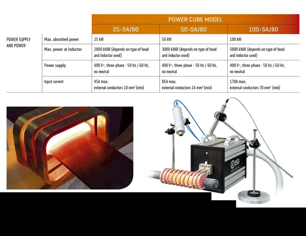
2 PW3-25-SA/80 PW3-50-SA/80 PW3-100-SA/ Generator Power [kw]
3 100-SA/80 Generator Overall Dimensions 25-SA/80 and 50-SA/80 Generator
 (KVAR) (W x L x H) (Kg) PWH-22 19-42 5000 336 x 328 x 266")


4 PWH-22 PWH-20 PWH-24 Capacity Output Power Dimensions (mm) Weight Model (uf) (KVAR) (W x L x H) (Kg) PWH x 328 x PWH x 328x PWH x 285 x PW3-100-SA/80 PW3-50-SA/80 PW3-25-SA/80 Magnetic Metals i.e. Carbon Steel C40, C45, AISI 420, Nickel PWH-20 PWH-24 PWH-24 Non Magnetic Metals i.e. Stainless Steel, Aluminum, Brass Copper PWH-22 PWH-20 PWH-20

5 Main Features SA Series Generators Automatic tracking and best optimization to load Constant, repeatable power generation via microprocessor control Continuous generation Minimum cooling water flow required High Safety: output isolated from the mains Highly integrated with a small footprint User Friendly Operations through graphical touch-screen interface Stainless Steel casing State-of-the-art electronics Built-in Self-diagnosis Compliant with the Regulations on Electrical Safety and Electromagnetic Compatibility Data Log System and built-in Web server Overall efficiency greater than 96% and maximum operational flexibility

 Continuous monitoring of: - Inductor Current - Inductor Voltage - Output Power - Working frequency -")
6 Maximum operational Flexibility Main Features SA Series Generators Automatic tracking and best optimization to load The Auto-Learn Function allows Generator parameters automatic tuning for low medium or high impedance loads Extended Working Frequency Range: khz Very wide coil admitted inductance range Output Power Set: from 2% to 100% (linear) Resolution: - Digital 1% - Analog 0,1% Output Power Stability : ± 0,1 % Power Cable can be disconnected from Heating Head Standard Cable Length: 3meter Custom Length: Upon Request Touch-screen interface (Web server) Continuous monitoring of: - Inductor Current - Inductor Voltage - Output Power - Working frequency - Heating Temperature
7 Main Features SA Series Generators Overall Efficiency greater than 96% New Stand Alone Generator Hardware Layout New Heating Head hardware layout To minimize the power loss on the capacitor block Automatic Best optimization to load In order to maximize the power transferred to the workpiece Minimum cooling water flow required Independent Generator+Heating Head and Coil cooling circuits. Two independent circuits with specific water flow and water temperature monitoring on each one) Focus on Generator and Coil Efficiency

![Coil used for the test Coil 1 Coil 2 Coil 3 Coil 4 Coil 5 Coil # Ø internal [mm] Loops](/docs-images/92/108462849/images/8-2.jpg "number Copper Tubing [mm] Coil 1 140 3 10/8 Coil 2 118 3 10/8 Coil 3 95 3 10/8 Coil 4 95 3")
8 Coil Efficiency Calculation Test Resume: The comparison will be carried out using different coils, and different metals. Coil used for the test Coil 1 Coil 2 Coil 3 Coil 4 Coil 5 Coil # Ø internal [mm] Loops number Copper Tubing [mm] Coil /8 Coil /8 Coil /8 Coil /6 Coil x6 140 mm 118 mm 95 mm Coil Øint Comparison Scale 1:20
 and fed by a Function")
 V coil R 500 Ω V1 The Frequency of")


9 Coil Efficiency Calculation Each Coil have been connected to a Heating Head (Capacitor Block) and fed by a Function Generator Measured Value: Resonant Frequency V1 (provided by Function Generator) V coil R 500 Ω V1 The Frequency of the Sine Wave Signal, provided by the Function Generator is manually tuned up to the resonant frequency of the L-C system (Head + Coil) V coil In resonant condition the two signals: V coil V1 = V Function Generator are in phase
 So the coil inductive value is calculated by the equation: 1 f resonant = 2π LC L = 1 4π 2 f 2 C = 1 4 3,14 2 28.000 2 (19 10 6 ) V coil = 1,7 uh 19 μ")
10 The capacity of the Heating Head is known (i.e. 19 μf) Equivalent Circuit of Heating Head+Coil with no load (1) The resonant frequency is determined when the system is in resonant condition (i.e. 28 khz) So the coil inductive value is calculated by the equation: 1 f resonant = 2π LC L = 1 4π 2 f 2 C = 1 4 3, ( ) V coil = 1,7 uh 19 μ
11 Equivalent Circuit of Heating Head+Coil with no load (2) Using the simulator LTSpice, we insert in the model the R resistor to calculate the losses on coil. The value of R is manually adjusted until the simulator calculates the same V coil as the measured one. R 3.95 m We find R= 3,95 m ohm
 R 3.")
12 The head cooling water temperature increment (ΔT 1 ) and the coil cooling water (ΔT 2 ) are measured, by running the generator with the water connection indicated below. Equivalent Circuit of Heating Head+Coil with no load (3) R 3.95 m We calculate ΔT 1 = 2,0 C ΔT 2 = 17,8 C ΔT 1 ΔT 2 Running the same current on L1 and C1 (resonant condition) it means that the losses on the coil are nearly 9 times higher than the losses on the head, in fact ΔT 1 ΔT 2 = 8,9
13 We add the resistor R3 to take in consideration the losses on the heating head. The resistor R2 allow the calculation of the losses on the coil only. The two resistors are in series so: R = R 2 + R 3 = 3,95 m ohm Final Equivalent Circuit of Heating Head+Coil with no load (4) and R 2 R 3 = 8,9 We obtain: R 2 = 3,55 m ohm R 3 = 0,40 m ohm This is the Mathematic Model of the system, with the coil empty. R 2 R 3 = ΔT 1 ΔT 2 = 8,9

 Of")
 -")
14 Now, following exactly the same procedure as before, we insert a metallic piece into the coil (i.e. carbon steel) and we calculate the new mathematic model, the new equivalent circuit Equivalent Circuit of Heating Head + Coil with Load (1) Of course, compared with the previous case (empty coil), now the system works with: - Different Resonant Frequency (a new L value has to be calculated; This is taken in account by paralleling the inductor L2) - Lower V coil (a new R2 value has to be calculated, we add R4 ) To simplify the calculation we consider that R3 remains constant In fact could be slightly affected by the different resonant frequency
 Head+ Coil +")


15 This is final the equivalent circuit of the system: Heating Head + Coil + Work Piece Equivalent Circuit of Heating Head + Coil with Load (2) Head+ Coil + WorkPiece We underline that the Mathematic model depends on the coil shape and heating head used. It is independent from the Induction Heating Generator used The same procedure has been carried out placing into the coil metallic rods, with exactly the same diameter (Ø85mm) made of: - Carbon Steel - Stainless Steel AISI Copper - Brass
16 Coil #1 Loops: 3 Ø140mm 10/8mm tubing 19uF #2 Loops: 3 Ø118mm 10/8mm tubing 19uF #3 Loops: 3 Ø95mm 10/8mm tubing 19uF #4 Loops: 3 Ø95mm 8/6mm tubing 19uF #5 Loops: 1 Ø95mm 30x6mm tubing 19uF Parameters Empty Resuming Table Carbon Steel Stainless Steel Copper Coil Efficiency Calculation Brass Coil Parameters Empty Carbon Steel Stainless Steel Frequency [Hz] Frequency [Hz] V coil [V rms] 2,42 0,35 0,84 1,64 1,46 V coil [V rms] 1,44 0,21 0,49 0,95 0,85 #1 L tot [H] 1,76 E-06 1,64 E-06 1,44 E-06 1,45 E-06 1,45 E-06 Loops: 3 L tot [H] 1,75 E-06 1,67 E-06 1,44 E-06 1,44 E-06 1,44 E-06 L2 L Workpiece [H] 2,39 E-05 8,00 E-06 8,00 E-06 8,32 E-06 Ø140mm L2 L Workpiece [H] 3,99 E-05 8,20 E-06 8,09 E-06 8,28 E-06 R2 R coil [mω] 3,55 3,55 3,55 3,55 3,55 10/8mm tubing R2 R coil [mω] 2,85 2,85 2,85 2,85 2,85 R4 R Workpiece [mω] 22,25 5,6 0,7 1,55 42uF R4 R Workpiece [mω] 17,65 4,35 0,7 1,2 Power coil [KW] 100,0 13,8 38,8 83,5 69,6 Power coil [KW] 100,0 13,9 39,6 80,3 70,4 Powe Workpiece [KW] 0,0 86,2 61,2 16,5 30,4 Powe Workpiece [KW] 0,0 86,1 60,4 19,7 29,6 Frequency [Hz] Frequency [Hz] V coil [V rms] 2,21 0,20 0,41 1,15 0,98 V coil [V rms] 1,29 0,13 0,28 0,66 0,57 #2 L tot [H] 1,40 E-06 1,27 E-06 1,01 E-06 1,01 E-06 1,01 E-06 Loops: 3 L tot [H] 1,39 E-06 1,29 E-06 1,00 E-06 9,94 E-07 1,01 E-06 L2 L Workpiece [H] 1,33 E-05 3,54 E-06 3,57 E-06 3,67 E-06 Ø118mm L2 L Workpiece [H] 1,79 E-05 3,56 E-03 3,46 E-03 3,67 E-06 R2 R coil [mω] 3,03 3,03 3,03 3,03 3,03 10/8mm tubing R2 R coil [mω] 2,47 2,47 2,47 2,47 2,47 R4 R Workpiece [mω] 33,97 10,47 1,47 2,34 42uF R4 R Workpiece [mω] 24 6,73 1,175 1,86 Power coil [KW] 100,0 8,2 22,4 67,3 56,4 Power coil [KW] 100,0 9,3 26,8 67,8 57,0 Powe Workpiece [KW] 0,0 91,8 77,6 32,7 43,6 Powe Workpiece [KW] 0,0 90,7 73,2 32,2 43,0 Frequency [Hz] Frequency [Hz] L2 V coil [V rms] 1,84 0,11 0,18 0,52 0,44 V coil [V rms] 1,07 0,10 0,11 0,31 0,26 #3 L tot [H] 1,11 E-06 9,36 E-07 5,66 E-07 5,67 E-07 5,89 E-07 L tot [H] 1,10 E-06 1,02 E-06 5,74 E-07 5,64 E-07 5,85 E-07 Loops: 3 L Workpiece [H] 5,90 E-06 1,15 E-06 1,15 E-03 1,25 E-06 L2 L Workpiece [H] 1,49 E-05 1,20 E-06 1,16 E-06 1,26 E-03 Ø95mm R2 R coil [mω] 2,9 2,9 2,9 2,9 2,9 10/8mm tubing R2 R coil [mω] 2,4 2,4 2,4 2,4 2,4 R4 R Workpiece [mω] 48,1 15,1 2,8 4,2 42uF R4 R Workpiece [mω] 24,6 11,4 2,11 3,2 Power coil [KW] 100,0 5,7 16,1 50,9 40,8 Power coil [KW] 100,0 8,9 17,4 53,2 42,9 Powe Workpiece [KW] 0,0 94,3 83,9 49,1 59,2 Powe Workpiece [KW] 0,0 91,1 82,6 46,8 57,1 Frequency [Hz] Frequency [Hz] V coil [V rms] 1,73 0,10 0,14 0,43 0,36 V coil [V rms] 1,01 0,07 0,09 0,25 0,21 #4 L tot [H] 1,16 E-06 9,92 E-07 5,50 E-07 5,50 E-07 5,75 E-07 L tot [H] 1,15 E-06 1,07 E-06 5,66 E-07 5,44 E-07 5,77 E-07 Loops: 3 L2 L Workpiece [H] 6,69 E-06 1,04 E-06 1,04 E-03 1,14 E-06 Ø95mm L2 L Workpiece [H] 1,54 E-05 1,12 E-03 1,05 E-06 1,16 E-03 R2 R coil [mω] 3,35 3,35 3,35 3,35 3,35 8/6mm tubing R2 R coil [mω] 2,6 2,6 2,6 2,6 2,6 R4 R Workpiece [mω] 56,65 18,85 3,4 5,35 42uF R4 R Workpiece [mω] 39,4 14,2 2,65 4,1 Power coil [KW] 100,0 5,6 15,1 49,6 38,5 Power coil [KW] 100,0 6,2 15,5 49,5 38,8 Powe Workpiece [KW] 0,0 94,4 84,9 50,4 61,5 Powe Workpiece [KW] 0,0 93,8 84,5 50,5 61,2 Frequency [Hz] Frequency [Hz] V coil [V rms] 0,65 0,07 0,12 0,28 0,25 V coil [V rms] 0,35 0,05 0,09 0,16 0,15 #5 L tot [H] 1,84 E-07 1,49 E-07 1,09 E-07 1,13 E-07 1,16 E-07 L tot [H] 1,85 E-07 1,55 E-07 1,14 E-07 1,16 E-07 1,18 E-07 Loops: 1 L2 L Workpiece [H] 7,66 E-07 2,68 E-07 2,90 E-07 3,09 E-07 L2 L Workpiece [H] 9,51 E-07 2,93 E-07 3,06 E-07 3,22 E-07 Ø95mm R2 R coil [mω] 1,18 1,18 1,18 1,18 1,18 R2 R coil [mω] 1,143 1,143 1,143 1,143 1,143 30x6mm tubing R4 R Workpiece [mω] 10,52 3,66 0,73 1 R4 R Workpiece [mω] 7,157 1,957 0,457 0,717 42uF Power coil [KW] 100,0 35,7 48,3 68,5 66,5 Power coil [KW] 100,0 13,8 36,9 71,4 61,5 Powe Workpiece [KW] 0,0 64,3 51,7 31,5 33,5 Powe Workpiece [KW] 0,0 86,2 63,1 28,6 38,5 Copper Brass
![Power to Workpiece [%] Coil Efficiency with 19 uf Heating Head 100,0 80,0 60,0 40,0 Carbon Steel 19 uf Stainless Steel 19 uf Copper 19 uf Brass 19 uf 20,0 0,0 1 2 3 4 5 Coil](/docs-images/92/108462849/images/17-1.jpg "# Coil Øint Comparison Scale 1:20 Coil # Ø internal [mm] Loops number Copper Tubing [mm] Coil 1 140 3 10/8 Coil 2 118 3 10/8 Coil 3 95 3 10/8 Coil 4 95 3 8/6 Coil 5 95 1")
17 Power to Workpiece [%] Coil Efficiency with 19 uf Heating Head 100,0 80,0 60,0 40,0 Carbon Steel 19 uf Stainless Steel 19 uf Copper 19 uf Brass 19 uf 20,0 0, Coil # Coil Øint Comparison Scale 1:20 Coil # Ø internal [mm] Loops number Copper Tubing [mm] Coil /8 Coil /8 Coil /8 Coil /6 Coil x6

 to calculate the losses on the")
18 Cable Cable Serial vs. Parallel Resonance The Mathematic Models determined are now used to calculate the: - Voltage - Current on the heading head cable to be provided by ideal Generators to deliver 100kW of Power: Ideal Generator Parallel Resonance Generator Head + Coil + WorkPiece Example Coil 1x95 42uF with Cu workpiece Serial Resonance Generator Ideal Generator Head + Coil + WorkPiece Simulating the system in order to absorb 100 kw from the Generator, we measure: - Voltage on the Head Cable= 415 V rms - Current on the Head Cable= 240 A rms We add the resistor (R capacitor) to calculate the losses on the capacitors block Simulating the system in order to absorb 100 kw from the Generator, we measure: - Voltage on the Head Cable= 416 V rms - Current on the Head Cable= 7950 A rms It s absolutely necessary to use a Transformer to reduce the current on the Head s Cable and on the active component as well


19 Parallel Resonance Generator Serial Resonance Generator With this configuration: Simulating the system in order to absorb 100 kw from the Generator, we measure: - Voltage on the Head Cable= 390 V rms - Current on the Head Cable= 268 A rms - Current on the Load = 7380 A rms At the next page is explained how the losses on the Transformer have been calculated With this configuration: Simulating the system in order to absorb 100 kw from the Generator, we measure: - Voltage on the Head Cable= 2500 V rms - Current on the Head Cable= 513 A rms - Current on the Load = 6320 A rms

 haven t been")


20 Series Resonant System : Matching Transformer Mathematic Model The magnetic losses (dispersed field) haven t been taken in consideration. So we consider: Reactive Power Transfer=100% Considering Active efficiency = 97% and connecting the transformer to a load that absorbs 6000 A, it means 30kW lost on a 1000 kw load

21 LT Spice software Running Simulation Example

![Head Cable [A rms] 256 526 Power Workpiece [kw] 83,8 77,8 Power Coil [kw] 13,4 12,4 Power Capacitors [kw] 2,4 Power Tranfromer [kw] 9,8 Resonant Frequency [khz] 62 62 Voltage on Head Cable [V rms]](/docs-images/92/108462849/images/22-2.jpg "210 1200 Current on Head Cable [A rms] 480 550 Coil #6 Inductor holders length= 30mm Coil #4 Loops: 3 Øint=95mm 8/6mm Tubing (19 uf Head) material: COPPER Coil #4 Loops: 3 Øint=95mm 8/6mm Tubing (19")
22 Frequency Limit Results Coil Parameter Parallel Series Coil #6 Loops: 1 Øint=95mm 30x6mm Tubing (42 uf Head) material: COPPER Coil #6 Loops: 1 Øint=95mm 30x6mm Tubing (42 uf Head) material: Carbon STEEL Power Workpiece [kw] 25,3 18,3 Power Coil [kw] 63,3 45,6 Power Capacitors [kw] 11,1 Power Tranfromer [kw] 35,9 Resonant Frequency [khz] Voltage on Head Cable [V rms] Current on Head Cable [A rms] Power Workpiece [kw] 83,8 77,8 Power Coil [kw] 13,4 12,4 Power Capacitors [kw] 2,4 Power Tranfromer [kw] 9,8 Resonant Frequency [khz] Voltage on Head Cable [V rms] Current on Head Cable [A rms] Coil #6 Inductor holders length= 30mm Coil #4 Loops: 3 Øint=95mm 8/6mm Tubing (19 uf Head) material: COPPER Coil #4 Loops: 3 Øint=95mm 8/6mm Tubing (19 uf Head) material: Carbon STEEL Power Workpiece [kw] 47,8 44,5 Power Coil [kw] 47,1 43,9 Power Capacitors [kw] 5,6 Power Tranfromer [kw] 11,8 Resonant Frequency [khz] Voltage on Head Cable [V rms] Current on Head Cable [A rms] Power Workpiece [kw] 93,9 93,3 Power Coil [kw] 5,7 5,7 Power Capacitors [kw] 0,7 Power Tranfromer [kw] 1,5 Resonant Frequency [khz] Voltage on Head Cable [V rms] Current on Head Cable [A rms] Voltage Limit
23 Results Coil Parameter Parallel Series Coil #6 Loops: 1 Øint=95mm 30x6mm Tubing (42 uf Head) material: COPPER Coil #6 Loops: 1 Øint=95mm 30x6mm Tubing (42 uf Head) material: Carbon STEEL Power Workpiece [kw] 25,3 18,3 Power Coil [kw] 63,3 45,6 Power Capacitors [kw] 11,1 Power Tranfromer [kw] 35,9 Resonant Frequency [khz] Voltage on Head Cable [V rms] Current on Head Cable [A rms] Power Workpiece [kw] 83,8 77,8 Power Coil [kw] 13,4 12,4 Power Capacitors [kw] 2,4 Power Tranfromer [kw] 9,8 Resonant Frequency [khz] Voltage on Head Cable [V rms] Current on Head Cable [A rms] Coil #4 Loops: 3 Øint=95mm 8/6mm Tubing (19 uf Head) material: COPPER Coil #4 Loops: 3 Øint=95mm 8/6mm Tubing (19 uf Head) material: Carbon STEEL Power Workpiece [kw] 47,8 44,5 Power Coil [kw] 47,1 43,9 Power Capacitors [kw] 5,6 Power Tranfromer [kw] 11,8 Resonant Frequency [khz] Voltage on Head Cable [V rms] Current on Head Cable [A rms] Power Workpiece [kw] 93,9 93,3 Power Coil [kw] 5,7 5,7 Power Capacitors [kw] 0,7 Power Tranfromer [kw] 1,5 Resonant Frequency [khz] Voltage on Head Cable [V rms] Current on Head Cable [A rms] % efficiency


24 CEIA Generator structure Head + Coil + WorkPiece Ideal Current Generator connected to load Ideal current generator CEIA Generator Output Transformer Head Cable Head + Coil + WorkPiece Schematic layout Matching Network Matching Network Automatic Selection of the most suitable: - Generator Output impedance - Working Band Galvanic insulator transformer Load Matching and User Safety. The operator is physically isolated from the power supply line Possible Settings: - 4:2-4:3-4:4 Low/Medium /High Impedance
![Output Power [kw] 105 100 95 90 85 80 75 70 65 60 55 50 45 40 35 30 25 20 15 10 5 0 AUTOLEARN Function Impedance Adaption, Output Transformer Setting Generator Output Power vs.](/docs-images/92/108462849/images/25-1.jpg "Coil Voltage 0 50 100 150 200 250 300 350 400 450 500 550 600 650 700 750 800 850 900 950 Coil Voltage [V rms] Trasf High Impedance Setting 4:4 Trasf Med Setting Impedance 4:3 Trasf Low")
25 Output Power [kw] AUTOLEARN Function Impedance Adaption, Output Transformer Setting Generator Output Power vs. Coil Voltage Coil Voltage [V rms] Trasf High Impedance Setting 4:4 Trasf Med Setting Impedance 4:3 Trasf Low Setting Impedance 4:2
![P [kw] PW3-100-SA/80 Generator Output Power vs.](/docs-images/92/108462849/images/26-1.jpg "Working Frequency and Load Impedance R [Ohm] f")
26 P [kw] PW3-100-SA/80 Generator Output Power vs. Working Frequency and Load Impedance R [Ohm] f [khz]
![P [kw] P [kw] PW3-50-SA/80 PW3-50-SA/80 vs. PW3-720/50 Generator Output Power vs.](/docs-images/92/108462849/images/27-1.jpg ": - Working Frequency - Load Impedance Very wide Band Adjustment R [Ohm] f [khz] PW3-720/50 PW3-720/50 Output")
27 P [kw] P [kw] PW3-50-SA/80 PW3-50-SA/80 vs. PW3-720/50 Generator Output Power vs. : - Working Frequency - Load Impedance Very wide Band Adjustment R [Ohm] f [khz] PW3-720/50 PW3-720/50 Output transformer setting 16:6 R [Ohm] f [khz]
28
29
POWER CUBE SA/80 series
 POWER CUBE SA/80 series The 100, 50, 25 kw Green Generators Features / Benefits High Power output High level of performance with minimal operating costs Automatic tracking and best optimization to load
Properties of Inductor and Applications
 LABORATORY Experiment 3 Properties of Inductor and Applications 1. Objectives To investigate the properties of inductor for different types of magnetic material To calculate the resonant frequency of a
Chapter 30 Inductance, Electromagnetic. Copyright 2009 Pearson Education, Inc.
 Chapter 30 Inductance, Electromagnetic Oscillations, and AC Circuits 30-7 AC Circuits with AC Source Resistors, capacitors, and inductors have different phase relationships between current and voltage
ELECTROMAGNETIC INDUCTION AND ALTERNATING CURRENT (Assignment)
") ELECTROMAGNETIC INDUCTION AND ALTERNATING CURRENT (Assignment) 1. In an A.C. circuit A ; the current leads the voltage by 30 0 and in circuit B, the current lags behind the voltage by 30 0. What is the
ELECTROMAGNETIC INDUCTION AND ALTERNATING CURRENT (Assignment) 1. In an A.C. circuit A ; the current leads the voltage by 30 0 and in circuit B, the current lags behind the voltage by 30 0. What is the
BEST BMET CBET STUDY GUIDE MODULE ONE
 BEST BMET CBET STUDY GUIDE MODULE ONE 1 OCTOBER, 2008 1. The phase relation for pure capacitance is a. current leads voltage by 90 degrees b. current leads voltage by 180 degrees c. current lags voltage
AP Physics C. Alternating Current. Chapter Problems. Sources of Alternating EMF
 AP Physics C Alternating Current Chapter Problems Sources of Alternating EMF 1. A 10 cm diameter loop of wire is oriented perpendicular to a 2.5 T magnetic field. What is the magnetic flux through the
LEP RLC Circuit
 RLC Circuit LEP Related topics Kirchhoff s laws, series and parallel tuned circuit, resistance, capacitance, inductance, phase displacement, Q-factor, band-width, loss resistance, damping Principle The
Core Technology Group Application Note 6 AN-6
 Characterization of an RLC Low pass Filter John F. Iannuzzi Introduction Inductor-capacitor low pass filters are utilized in systems such as audio amplifiers, speaker crossover circuits and switching power
QUESTION BANK ETE (17331) CM/IF. Chapter1: DC Circuits
 CM/IF. Chapter1: DC Circuits") QUESTION BANK ETE (17331) CM/IF Chapter1: DC Circuits Q1. State & explain Ohms law. Also explain concept of series & parallel circuit with the help of diagram. 3M Q2. Find the value of resistor in fig.
QUESTION BANK ETE (17331) CM/IF Chapter1: DC Circuits Q1. State & explain Ohms law. Also explain concept of series & parallel circuit with the help of diagram. 3M Q2. Find the value of resistor in fig.
Study of Inductive and Capacitive Reactance and RLC Resonance
 Objective Study of Inductive and Capacitive Reactance and RLC Resonance To understand how the reactance of inductors and capacitors change with frequency, and how the two can cancel each other to leave
Radio Frequency Electronics
 Radio Frequency Electronics Frederick Emmons Terman Transformers Masters degree from Stanford and Ph.D. from MIT Later a professor at Stanford His students include William Hewlett and David Packard Wrote
Figure 1: Closed Loop System
 SIGNAL GENERATORS 3. Introduction Signal sources have a variety of applications including checking stage gain, frequency response, and alignment in receivers and in a wide range of other electronics equipment.
Core Technology Group Application Note 1 AN-1
 Measuring the Impedance of Inductors and Transformers. John F. Iannuzzi Introduction In many cases it is necessary to characterize the impedance of inductors and transformers. For instance, power supply
Sample Question Paper
 Scheme G Sample Question Paper Course Name : Electrical Engineering Group Course Code : EE/EP Semester : Third Subject Title : Electrical Circuit and Network 17323 Marks : 100 Time: 3 hrs Instructions:
Question Paper Profile
 I Scheme Question Paper Profile Program Name : Electrical Engineering Program Group Program Code : EE/EP/EU Semester : Third Course Title : Electrical Circuits Max. Marks : 70 Time: 3 Hrs. Instructions:
Downloaded from / 1
 PURWANCHAL UNIVERSITY II SEMESTER FINAL EXAMINATION-2008 LEVEL : B. E. (Computer/Electronics & Comm.) SUBJECT: BEG123EL, Electrical Engineering-I Full Marks: 80 TIME: 03:00 hrs Pass marks: 32 Candidates
General Physics (PHY 2140)
") General Physics (PHY 2140) Lecture 11 Electricity and Magnetism AC circuits and EM waves Resonance in a Series RLC circuit Transformers Maxwell, Hertz and EM waves Electromagnetic Waves 6/18/2007 http://www.physics.wayne.edu/~alan/2140website/main.htm
General Physics (PHY 2140) Lecture 11 Electricity and Magnetism AC circuits and EM waves Resonance in a Series RLC circuit Transformers Maxwell, Hertz and EM waves Electromagnetic Waves 6/18/2007 http://www.physics.wayne.edu/~alan/2140website/main.htm
ET1210: Module 5 Inductance and Resonance
 Part 1 Inductors Theory: When current flows through a coil of wire, a magnetic field is created around the wire. This electromagnetic field accompanies any moving electric charge and is proportional to
Project: Electromagnetic Ring Launcher
 Project: Electromagnetic Ring Launcher Introduction: In science museums and physics-classrooms an experiment is very commonly demonstrated called the Jumping Ring or Electromagnetic Ring Launcher. The
AC Power Transmission Training System Add- On to ( )
") AC Power Transmission Training System Add- On to 8006 587433 (89252-00) LabVolt Series Datasheet Festo Didactic en 120 V - 60 Hz 03/2019 Table of Contents General Description 2 List of Equipment 2 List
AC Power Transmission Training System Add- On to 8006 587433 (89252-00) LabVolt Series Datasheet Festo Didactic en 120 V - 60 Hz 03/2019 Table of Contents General Description 2 List of Equipment 2 List
not to be republished NCERT ALTERNATING CURRENT Chapter Seven MCQ 1
 hapter Seven ALTERNATING URRENT MQ 1 7.1 If the rms current in a 50 Hz ac circuit is 5 A, the value of the current 1/300 seconds after its value becomes zero is (a) 5 2 A (b) 5 3/2 A (c) 5/6 A (d) 5/ 2
Class XII Chapter 7 Alternating Current Physics
 Question 7.1: A 100 Ω resistor is connected to a 220 V, 50 Hz ac supply. (a) What is the rms value of current in the circuit? (b) What is the net power consumed over a full cycle? Resistance of the resistor,
SELECTION GUIDE. Nominal Input Voltage Output Voltage. Output Current
 www.murata-ps.com SELECTION GUIDE Order Code Nominal Input Voltage Output Current Input Current at Rated Load Load Regulation (Typ) Load Regulation (Max) Ripple & Noise (Typ) 1 Ripple & Noise (Max) 1 Efficiency
EE301 ELECTRONIC CIRCUITS CHAPTER 2 : OSCILLATORS. Lecturer : Engr. Muhammad Muizz Bin Mohd Nawawi
 EE301 ELECTRONIC CIRCUITS CHAPTER 2 : OSCILLATORS Lecturer : Engr. Muhammad Muizz Bin Mohd Nawawi 2.1 INTRODUCTION An electronic circuit which is designed to generate a periodic waveform continuously at
Exam 3 Solutions. ! r, the ratio is ( N ) ( ) ( )( ) 2. PHY2054 Spring Prof. Pradeep Kumar Prof. Paul Avery Prof. Yoonseok Lee Mar.
 ( ) ( )( ) 2. PHY2054 Spring Prof. Pradeep Kumar Prof. Paul Avery Prof. Yoonseok Lee Mar.") PHY054 Spring 009 Prof. Pradeep Kumar Prof. Paul Avery Prof. Yoonseok Lee Mar. 7, 009 Exam 3 Solutions 1. Two coils (A and B) made out of the same wire are in a uniform magnetic field with the coil axes
PHY054 Spring 009 Prof. Pradeep Kumar Prof. Paul Avery Prof. Yoonseok Lee Mar. 7, 009 Exam 3 Solutions 1. Two coils (A and B) made out of the same wire are in a uniform magnetic field with the coil axes
Electron Spin Resonance v2.0
 Electron Spin Resonance v2.0 Background. This experiment measures the dimensionless g-factor (g s ) of an unpaired electron using the technique of Electron Spin Resonance, also known as Electron Paramagnetic
Exercise 1: Series Resonant Circuits
 Series Resonance AC 2 Fundamentals Exercise 1: Series Resonant Circuits EXERCISE OBJECTIVE When you have completed this exercise, you will be able to compute the resonant frequency, total current, and
Aligarh College of Engineering & Technology (College Code: 109) Affiliated to UPTU, Approved by AICTE Electrical Engg.
 Affiliated to UPTU, Approved by AICTE Electrical Engg.") Aligarh College of Engineering & Technology (College Code: 19) Electrical Engg. (EE-11/21) Unit-I DC Network Theory 1. Distinguish the following terms: (a) Active and passive elements (b) Linearity and
Aligarh College of Engineering & Technology (College Code: 19) Electrical Engg. (EE-11/21) Unit-I DC Network Theory 1. Distinguish the following terms: (a) Active and passive elements (b) Linearity and
Understanding and Optimizing Electromagnetic Compatibility in Switchmode Power Supplies
 Understanding and Optimizing Electromagnetic Compatibility in Switchmode Power Supplies 1 Definitions EMI = Electro Magnetic Interference EMC = Electro Magnetic Compatibility (No EMI) Three Components
Electronic Instrumentation
 10/1/014 1 Electronic Instrumentation Experiment 3 Part A: Making an Inductor Part B: Measurement of Inductance Part C: imulation of a Transformer Part D: Making a Transformer Inductors & Transformers
Methods of secondary short circuit current control in single phase transformers
 2015; 1(8): 412-417 ISSN Print: 2394-7500 ISSN Online: 2394-5869 Impact Factor: 5.2 IJAR 2015; 1(8): 412-417 www.allresearchjournal.com Received: 17-05-2015 Accepted: 20-06-2015 Parantap Nandi A/2, Building
CHAPTER 6: ALTERNATING CURRENT
 CHAPTER 6: ALTERNATING CURRENT PSPM II 2005/2006 NO. 12(C) 12. (c) An ac generator with rms voltage 240 V is connected to a RC circuit. The rms current in the circuit is 1.5 A and leads the voltage by
Department of Electrical and Computer Engineering Lab 6: Transformers
 ESE Electronics Laboratory A Department of Electrical and Computer Engineering 0 Lab 6: Transformers. Objectives ) Measure the frequency response of the transformer. ) Determine the input impedance of
VE7CNF - 630m Antenna Matching Measurements Using an Oscilloscope
 VE7CNF - 630m Antenna Matching Measurements Using an Oscilloscope Toby Haynes October, 2016 1 Contents VE7CNF - 630m Antenna Matching Measurements Using an Oscilloscope... 1 Introduction... 1 References...
Radio Frequency Electronics
 Radio Frequency Electronics Preliminaries II Guglielmo Giovanni Maria Marconi Thought off by many people as the inventor of radio Pioneer in long-distance radio communications Shared Nobel Prize in 1909
Telemetrie-Messtechnik Schnorrenberg
 Telemetrie-Messtechnik Schnorrenberg MTP-IND-PWR User Manual Inductive power supply set Power supply for power head 25 and 50mm mounting tape to fix coil on shaft Ferrite tape 30mmx3m CUL 1.00 mm (Enamelled
Electronic Instrumentation
 10/15/01 1 Electronic Instrumentation Experiment 3 Part A: Making an Inductor Part B: Measurement of Inductance Part C: imulation of a Transformer Part D: Making a Transformer Review RC and Resonance How
The Ins and Outs of Audio Transformers. How to Choose them and How to Use them
 The Ins and Outs of Audio Transformers How to Choose them and How to Use them Steve Hogan Product Development Engineer, Jensen Transformers 1983 1989 Designed new products and provided application assistance
Resonance. A resonant circuit (series or parallel) must have an inductive and a capacitive element.
 must have an inductive and a capacitive element.") 1. Series Resonant: Resonance A resonant circuit (series or parallel) must have an inductive and a capacitive element. The total impedance of this network is: The circuit will reach its maximum Voltage
1. Series Resonant: Resonance A resonant circuit (series or parallel) must have an inductive and a capacitive element. The total impedance of this network is: The circuit will reach its maximum Voltage
15. the power factor of an a.c circuit is.5 what will be the phase difference between voltage and current in this
 1 1. In a series LCR circuit the voltage across inductor, a capacitor and a resistor are 30 V, 30 V and 60 V respectively. What is the phase difference between applied voltage and current in the circuit?
Induction heating of internal
 OPTIMAL DESIGN OF INTERNAL INDUCTION COILS The induction heating of internal surfaces is more complicated than heating external ones. The three main types of internal induction coils each has its advantages
Lab E2: B-field of a Solenoid. In the case that the B-field is uniform and perpendicular to the area, (1) reduces to
 reduces to") E2.1 Lab E2: B-field of a Solenoid In this lab, we will explore the magnetic field created by a solenoid. First, we must review some basic electromagnetic theory. The magnetic flux over some area A is
E2.1 Lab E2: B-field of a Solenoid In this lab, we will explore the magnetic field created by a solenoid. First, we must review some basic electromagnetic theory. The magnetic flux over some area A is
QEG Instructions for Engineers
 QEG Instructions for Engineers By James Robitaille FTW QEG Engineering Artist -Exciter Coil -Tuning -Core Conditioning -Power Conversion Greetings and Blessings to all our supporters! In lieu of the fact
Oscillators. An oscillator may be described as a source of alternating voltage. It is different than amplifier.
 Oscillators An oscillator may be described as a source of alternating voltage. It is different than amplifier. An amplifier delivers an output signal whose waveform corresponds to the input signal but
No Brain Too Small PHYSICS
 ELECTRICITY: AC QUESTIONS No Brain Too Small PHYSICS MEASURING IRON IN SAND (2016;3) Vivienne wants to measure the amount of iron in ironsand mixtures collected from different beaches. The diagram below
INTRODUCTION TO FILTER CIRCUITS
 INTRODUCTION TO FILTER CIRCUITS 1 2 Background: Filters may be classified as either digital or analog. Digital filters are implemented using a digital computer or special purpose digital hardware. Analog
PART B. t (sec) Figure 1
 Figure 1") Code No: R16128 R16 SET 1 I B. Tech II Semester Regular Examinations, April/May 217 ELECTRICAL CIRCUIT ANALYSIS I (Electrical and Electronics Engineering) Time: 3 hours Max. Marks: 7 Note: 1. Question
Code No: R16128 R16 SET 1 I B. Tech II Semester Regular Examinations, April/May 217 ELECTRICAL CIRCUIT ANALYSIS I (Electrical and Electronics Engineering) Time: 3 hours Max. Marks: 7 Note: 1. Question
Homework Assignment 05
 Homework Assignment 05 Question (2 points each unless otherwise indicated)(20 points). Estimate the parallel parasitic capacitance of a mh inductor with an SRF of 220 khz. Answer: (2π)(220 0 3 ) = ( 0
ANADOLU UNIVERSITY FACULTY OF ENGINEERING AND ARCHITECTURE DEPARTMENT OF ELECTRICAL AND ELECTRONICS ENGINEERING
 ANADOLU UNIVERSITY FACULTY OF ENGINEERING AND ARCHITECTURE DEPARTMENT OF ELECTRICAL AND ELECTRONICS ENGINEERING EEM 206 ELECTRICAL CIRCUITS LABORATORY EXPERIMENT#3 RESONANT CIRCUITS 1 RESONANT CIRCUITS
Inductors & Resonance
 Inductors & Resonance The Inductor This figure shows a conductor carrying a current. A magnetic field is set up around the conductor as concentric circles. If a coil of wire has a current flowing through
150Hz to 1MHz magnetic field coupling to a typical shielded cable above a ground plane configuration
 150Hz to 1MHz magnetic field coupling to a typical shielded cable above a ground plane configuration D. A. Weston Lowfreqcablecoupling.doc 7-9-2005 The data and information contained within this report
Chapter Moving Charges and Magnetism
 100 Chapter Moving Charges and Magnetism 1. The power factor of an AC circuit having resistance (R) and inductance (L) connected in series and an angular velocity ω is [2013] 2. [2002] zero RvB vbl/r vbl
OPTIMIZATION OF AN INDUCTION COIL FOR ULF
 OPTIMIZATION OF AN INDUCTION COIL FOR ULF This paper is to dimostrate how to is possible to optimize an induction coil for ULF band (0.1-30Hz). My realization was inspire to Hans Michlmayr project. My
Physics Class 12 th NCERT Solutions
 Chapter.7 Alternating Current Class XII Subject Physics 7.1. A 100 Ω resistor is connected to a 220 V, 50 Hz ac supply. a) What is the rms value of current in the circuit? b) What is the net power consumed
(DOSA) VDC, 5.5 A.
 VDC, 5.5 A.") Features Industry-standard pinout Output: 15 V at 5.5 A, 82.5W max. No minimum load required Low height - 0.374 (9.5mm) max. Basic Insulation Withstands 100 V input transients Fixed-frequency operation
Features Industry-standard pinout Output: 15 V at 5.5 A, 82.5W max. No minimum load required Low height - 0.374 (9.5mm) max. Basic Insulation Withstands 100 V input transients Fixed-frequency operation
Experiment 5: Grounding and Shielding
 Experiment 5: Grounding and Shielding Power System Hot (Red) Neutral (White) Hot (Black) 115V 115V 230V Ground (Green) Service Entrance Load Enclosure Figure 1 Typical residential or commercial AC power
Figure 1a Three small inductors are show what inductors look like. Figure 1b Three large inductors
 A Series RLC Circuit This lab will let you learn the characteristics of both amplitude and phase of a series RLC circuit. Theory nductors and Capacitors Resistors (R), inductors (L) and capacitors (C)
Chapter 31 Alternating Current
 Chapter 31 Alternating Current In this chapter we will learn how resistors, inductors, and capacitors behave in circuits with sinusoidally vary voltages and currents. We will define the relationship between
Chapter 11. Alternating Current
 Unit-2 ECE131 BEEE Chapter 11 Alternating Current Objectives After completing this chapter, you will be able to: Describe how an AC voltage is produced with an AC generator (alternator) Define alternation,
PHASES IN A SERIES LRC CIRCUIT
 PHASES IN A SERIES LRC CIRCUIT Introduction: In this lab, we will use a computer interface to analyze a series circuit consisting of an inductor (L), a resistor (R), a capacitor (C), and an AC power supply.
NME Series Isolated 1W Single Output DC-DC Converters
 www.murata-ps.com NME Series SELECTION GUIDE Order Code Nominal Input Voltage Output Voltage Output Current Input Current at Rated Load V V ma ma Load Regulation 2 Ripple & Noise % mv p-p Typ. Max. Typ.
PE Electrical Machine / Power Electronics. Power Electronics Training System. ufeatures. } List of Experiments
 Electrical Machine / Power Electronics PE-5000 Power Electronics Training System The PE-5000 Power Electronics Training System consists of 28 experimental modules, a three-phase squirrel cage motor, load,
High Voltage Engineering
 High Voltage Engineering Course Code: EE 2316 Prof. Dr. Magdi M. El-Saadawi www.saadawi1.net E-mail : saadawi1@gmail.com www.facebook.com/magdi.saadawi 1 Contents Chapter 1 Introduction to High Voltage
Passive Component Analysis. OMICRON Lab Webinar Nov. 2015
 Passive Component Analysis OMICRON Lab Webinar Nov. 2015 Webinar Hints Activate the chat function Please mute your microphones to avoid echoes Feel free to post questions anytime using the chat function
Cool Power Technologies
 Cool Power Technologies Sixteenth-Brick Isolated DC/DC Converter Features Industry-standard pinout Wide input voltage range: 36 75Vin Output: 3.3 V at 12 A, 40W max. No minimum load required Low height
KINGS COLLEGE OF ENGINEERING DEPARTMENT OF ELECTRICAL AND ELECTRONICS ENGINEERING QUESTION BANK UNIT I BASIC CIRCUITS ANALYSIS PART A (2-MARKS)
") KINGS COLLEGE OF ENGINEERING DEPARTMENT OF ELECTRICAL AND ELECTRONICS ENGINEERING QUESTION BANK YEAR / SEM : I / II SUBJECT CODE & NAME : EE 1151 CIRCUIT THEORY UNIT I BASIC CIRCUITS ANALYSIS PART A (2-MARKS)
KINGS COLLEGE OF ENGINEERING DEPARTMENT OF ELECTRICAL AND ELECTRONICS ENGINEERING QUESTION BANK YEAR / SEM : I / II SUBJECT CODE & NAME : EE 1151 CIRCUIT THEORY UNIT I BASIC CIRCUITS ANALYSIS PART A (2-MARKS)
ELECTRICAL CIRCUITS LABORATORY MANUAL (II SEMESTER)
") ELECTRICAL CIRCUITS LABORATORY MANUAL (II SEMESTER) LIST OF EXPERIMENTS. Verification of Ohm s laws and Kirchhoff s laws. 2. Verification of Thevenin s and Norton s Theorem. 3. Verification of Superposition
ELECTRICAL CIRCUITS LABORATORY MANUAL (II SEMESTER) LIST OF EXPERIMENTS. Verification of Ohm s laws and Kirchhoff s laws. 2. Verification of Thevenin s and Norton s Theorem. 3. Verification of Superposition
Experiment 4: Grounding and Shielding
 4-1 Experiment 4: Grounding and Shielding Power System Hot (ed) Neutral (White) Hot (Black) 115V 115V 230V Ground (Green) Service Entrance Load Enclosure Figure 1 Typical residential or commercial AC power
SIDDHARTH GROUP OF INSTITUTIONS :: PUTTUR (AUTONOMOUS) Siddharth Nagar, Narayanavanam Road QUESTION BANK (DESCRIPTIVE) UNIT I INTRODUCTION
 Siddharth Nagar, Narayanavanam Road QUESTION BANK (DESCRIPTIVE) UNIT I INTRODUCTION") SIDDHARTH GROUP OF INSTITUTIONS :: PUTTUR (AUTONOMOUS) Siddharth Nagar, Narayanavanam Road 517583 QUESTION BANK (DESCRIPTIVE) Subject with Code : Electrical Circuits(16EE201) Year & Sem: I-B.Tech & II-Sem
SIDDHARTH GROUP OF INSTITUTIONS :: PUTTUR (AUTONOMOUS) Siddharth Nagar, Narayanavanam Road 517583 QUESTION BANK (DESCRIPTIVE) Subject with Code : Electrical Circuits(16EE201) Year & Sem: I-B.Tech & II-Sem
ENGR4300 Test 3A Fall 2002
 1. 555 Timer (20 points) Figure 1: 555 Timer Circuit For the 555 timer circuit in Figure 1, find the following values for R1 = 1K, R2 = 2K, C1 = 0.1uF. Show all work. a) (4 points) T1: b) (4 points) T2:
Lab E5: Filters and Complex Impedance
 E5.1 Lab E5: Filters and Complex Impedance Note: It is strongly recommended that you complete lab E4: Capacitors and the RC Circuit before performing this experiment. Introduction Ohm s law, a well known
PHYSICS WORKSHEET CLASS : XII. Topic: Alternating current
 PHYSICS WORKSHEET CLASS : XII Topic: Alternating current 1. What is mean by root mean square value of alternating current? 2. Distinguish between the terms effective value and peak value of an alternating
Transformer circuit calculations
 Transformer circuit calculations This worksheet and all related files are licensed under the Creative Commons Attribution License, version 1.0. To view a copy of this license, visit http://creativecommons.org/licenses/by/1.0/,
CHAPTER 4 MEASUREMENT OF NOISE SOURCE IMPEDANCE
 69 CHAPTER 4 MEASUREMENT OF NOISE SOURCE IMPEDANCE 4.1 INTRODUCTION EMI filter performance depends on the noise source impedance of the circuit and the noise load impedance at the test site. The noise
Coaxial Line Stretchers
 Coaxial Line Stretchers Frequency range (Note) Maximum Input NOTE: The frequency range will depend on the model. 1.Vibration 2.Shock DC to 10.0 GHz 50 W These coaxial line stretchers maintain an impedance
RS232 AC-DC VOLTAGE POWER AMPLIFIERS PCU-10K / 15K / 20K / 24K-AB/4G/HP PERFORMANCES APPLICATIONS DESCRIPTION COMMERCIAL REFERENCES
 PERFORMANCES High accuracy High stability Fast transients High inrush current facilities Wide bandwidth Very low distortion Quadrant change without transition Very low output impedance RS232 APPLICATIONS
University of Pennsylvania Moore School of Electrical Engineering ESE319 Electronic Circuits - Modeling and Measurement Techniques
 University of Pennsylvania Moore School of Electrical Engineering ESE319 Electronic Circuits - Modeling and Measurement Techniques 1. Introduction. Students are often frustrated in their attempts to execute
Lab 4: Analysis of the Stereo Amplifier
 ECE 212 Spring 2010 Circuit Analysis II Names: Lab 4: Analysis of the Stereo Amplifier Objectives In this lab exercise you will use the power supply to power the stereo amplifier built in the previous
Common myths, fallacies and misconceptions in Electromagnetic Compatibility and their correction.
 Common myths, fallacies and misconceptions in Electromagnetic Compatibility and their correction. D. A. Weston EMC Consulting Inc 22-3-2010 These are some of the commonly held beliefs about EMC which are
Experiment 8: An AC Circuit
 Experiment 8: An AC Circuit PART ONE: AC Voltages. Set up this circuit. Use R = 500 Ω, L = 5.0 mh and C =.01 μf. A signal generator built into the interface provides the emf to run the circuit from Output
DEPARTMENT OF ELECTRICAL ENGINEERING AND COMPUTER SCIENCE MASSACHUSETTS INSTITUTE OF TECHNOLOGY CAMBRIDGE, MASSACHUSETTS 02139
 DEPARTMENT OF ELECTRICAL ENGINEERING AND COMPUTER SCIENCE MASSACHUSETTS INSTITUTE OF TECHNOLOGY CAMBRIDGE, MASSACHUSETTS 02139 Spring Term 2007 6.101 Introductory Analog Electronics Laboratory Laboratory
Experiment 18: Driven RLC Circuit
 MASSACHUSETTS INSTITUTE OF TECHNOLOGY Department of Physics 8. Spring 3 Experiment 8: Driven LC Circuit OBJECTIVES To measure the resonance frequency and the quality factor of a driven LC circuit INTODUCTION
Lab 10 - INTRODUCTION TO AC FILTERS AND RESONANCE
 159 Name Date Partners Lab 10 - INTRODUCTION TO AC FILTERS AND RESONANCE OBJECTIVES To understand the design of capacitive and inductive filters To understand resonance in circuits driven by AC signals
MFJ-249B HF/VHF SWR ANALYZER
 TABLE OF CONTENTS MFJ-249B... 2 Introduction... 2 Powering The MFJ-249B... 3 Battery Installation... 3 Alkaline Batteries... 3 NiCd Batteries... 4 Power Saving Mode... 4 Operation Of The MFJ-249B...5 SWR
GLOSSARY OF TERMS FLUX DENSITY:
 ADSL: Asymmetrical Digital Subscriber Line. Technology used to transmit/receive data and audio using the pair copper telephone lines with speed up to 8 Mbps. AMBIENT TEMPERATURE: The temperature surrounding
RLC-circuits with Cobra4 Xpert-Link
 Student's Sheet RLC-circuits with Cobra4 Xpert-Link (Item No.: P2440664) Curricular Relevance Area of Expertise: Physics Subtopic: Inductance, Electromagnetic Oscillations, AC Circuits Topic: Electricity
SELECTION GUIDE. Nominal Input Voltage Output Voltage. Output Current
 www.murata-ps.com CRV2 Series SELECTION GUIDE Order Code Nominal Input Voltage Output Voltage Output Current Input Current at Rated Load Load Regulation (Typ) Load Regulation (Max) Ripple & Noise (Typ)
EE 221 L CIRCUIT II LABORATORY 4: AC CIRCUITS, CAPACITORS AND INDUCTORS UNIVERSITY OF NEVADA, LAS VEGAS OBJECTIVE COMPONENTS & EQUIPMENT BACKGROUND
 EE 221 L CIRCUIT II LABORATORY 4: AC CIRCUITS, CAPACITORS AND INDUCTORS DEPARTMENT OF ELECTRICAL AND COMPUTER ENGINEERING UNIVERSITY OF NEVADA, LAS VEGAS OBJECTIVE Compare the difference between DC and
MER1 Series 1kVDC Isolated 1W Single Output DC/DC Converters
 www.murata-ps.com MER1 Series SELECTION GUIDE Order Code Nominal Input Voltage Output Voltage Output Current Input Current at Rated Load Load Regulation (Typ) Load Regulation (Max) Ripple & Noise (Typ)
Resonant Frequency of the LRC Circuit (Power Output, Voltage Sensor)
") 72 Resonant Frequency of the LRC Circuit (Power Output, Voltage Sensor) Equipment List Qty Items Part Numbers 1 PASCO 750 Interface 1 Voltage Sensor CI-6503 1 AC/DC Electronics Laboratory EM-8656 2 Banana
72 Resonant Frequency of the LRC Circuit (Power Output, Voltage Sensor) Equipment List Qty Items Part Numbers 1 PASCO 750 Interface 1 Voltage Sensor CI-6503 1 AC/DC Electronics Laboratory EM-8656 2 Banana
Alternating Current. Slide 1 / 69. Slide 2 / 69. Slide 3 / 69. Topics to be covered. Sources of Alternating EMF. Sources of alternating EMF
 Slide 1 / 69 lternating urrent Sources of alternating EMF Transformers ircuits and Impedance Topics to be covered Slide 2 / 69 LR Series ircuits Resonance in ircuit Oscillations Sources of lternating EMF
Alternating Current. Slide 2 / 69. Slide 1 / 69. Slide 3 / 69. Slide 4 / 69. Slide 6 / 69. Slide 5 / 69. Topics to be covered
 Slide 1 / 69 lternating urrent Sources of alternating EMF ircuits and Impedance Slide 2 / 69 Topics to be covered LR Series ircuits Resonance in ircuit Oscillations Slide 3 / 69 Sources of lternating EMF
AC Circuit. What is alternating current? What is an AC circuit?
 Chapter 21 Alternating Current Circuits and Electromagnetic Waves 1. Alternating Current 2. Resistor in an AC circuit 3. Capacitor in an AC circuit 4. Inductor in an AC circuit 5. RLC series circuit 6.
LAB 8: Activity P52: LRC Circuit
 LAB 8: Activity P52: LRC Circuit Equipment: Voltage Sensor 1 Multimeter 1 Patch Cords 2 AC/DC Electronics Lab (100 μf capacitor; 10 Ω resistor; Inductor Coil; Iron core; 5 inch wire lead) The purpose of
RC and RL Circuits. Figure 1: Capacitor charging circuit.
 RC and RL Circuits Page 1 RC and RL Circuits RC Circuits In this lab we study a simple circuit with a resistor and a capacitor from two points of view, one in time and the other in frequency. The viewpoint
Class #7: Experiment L & C Circuits: Filters and Energy Revisited
 Class #7: Experiment L & C Circuits: Filters and Energy Revisited In this experiment you will revisit the voltage oscillations of a simple LC circuit. Then you will address circuits made by combining resistors
Applications Note RF Transmitter and Antenna Design Hints
 This application note covers the TH7107,TH71071,TH71072,TH7108,TH71081,TH72011,TH72031,TH7204 Single Frequency Transmitters. These transmitters have different features and cover different bands but they
The Tuned Circuit. Aim of the experiment. Circuit. Equipment and components. Display of a decaying oscillation. Dependence of L, C and R.
 The Tuned Circuit Aim of the experiment Display of a decaying oscillation. Dependence of L, C and R. Circuit Equipment and components 1 Rastered socket panel 1 Resistor R 1 = 10 Ω, 1 Resistor R 2 = 1 kω
Ileana-Diana Nicolae ICMET CRAIOVA UNIVERSITY OF CRAIOVA MAIN BUILDING FACULTY OF ELECTROTECHNICS
 The Designing, Realization and Testing of a Network Filter used to Reduce Electromagnetic Disturbances and to Improve the EMI for Static Switching Equipment Petre-Marian Nicolae Ileana-Diana Nicolae George
Advanced Topics in EMC Design. Issue 1: The ground plane to split or not to split?
 NEEDS 2006 workshop Advanced Topics in EMC Design Tim Williams Elmac Services C o n s u l t a n c y a n d t r a i n i n g i n e l e c t r o m a g n e t i c c o m p a t i b i l i t y e-mail timw@elmac.co.uk