High Voltage Engineering
|
|
|
- Beverley Golden
- 5 years ago
- Views:
Transcription
1 High Voltage Engineering Course Code: EE 2316 Prof. Dr. Magdi M. El-Saadawi saadawi1@gmail.com 1
2 Contents Chapter 1 Introduction to High Voltage Technology Chapter 2 Generation of High Voltages and Currents Chapter 3 Measurement of High Voltages and Currents Chapter 4 Breakdown Mechanism of Gases, Liquid and Solid Materials 2
3 Chapter 3 Measurement of High Voltages and Currents 3.1. Introduction 3.2. Measurement of High Direct Current Voltages High Ohmic Series Resistance with Microammeter Resistance Potential Dividers for d.c. Voltages Generating Voltmeters 3.3. Measurement of High A.C. and Impulse Voltages Series Impedance Voltmeters Capacitance Potential Dividers and Capacitance Voltage Transformers Electrostatic Voltmeters Peak Reading a.c. Voltmeters Spark Gaps Potential Dividers 3.4. Measurement of High A.C. and Impulse Currents Measurement of High Direct Currents Measurement of High Frequency and Impulse Currents Cathode Ray Oscillographs for Impulse Measurements 3.5. Solved Examples 3
4 Table 3.1 High voltage Measurement Techniques 4
5 Table 3.2 High Current Measurement Techniques 5
6 3.3 Measurement of High A.C. and Impulse Voltages Measurement of high a.c. voltages employ conventional methods like series impedance voltmeters, potential dividers, potential transformers, or electrostatic voltmeters. But their designs are different from those of low voltage meters, as the insulation design and source loading are the important criteria. When only peak value measurement is needed, peak voltmeters and sphere gaps can be used. Often, sphere gaps are used for calibration purposes. Impulse and high frequency a.c. measurements invariably use potential dividers with a cathode ray oscillograph for recording voltage waveforms. 6
7 3.3.1 Series Impedance Voltmeters For power frequency a.c. measurements the series impedance may be a pure resistance or a reactance. In H.V. a capacitor is preferred as series reactance because: Resistances involve power losses, For high resistances, the variation of resistance with temperature is a problem, and The residual inductance of the resistance gives rise to an impedance different from its ohmic resistance. High resistance units for HV have stray capacitances and have an equivalent circuit as shown. 7
8 3.3.1 Series Impedance Voltmeters The entire resistor unit then has to be taken as a transmission line equivalent, for calculating the effective resistance. Also, the ground or stray capacitance of each element influences the current flowing in the unit, and the indication of the meter results in an error. The equivalent circuit of a high voltage resistor neglecting inductance and the circuit of compensated series resistor using guard and timing resistors is shown in Figs. 3.5a and b respectively 8
9 9
10 3.3.1 Series Impedance Voltmeters In Fig. 3.5b stray ground capacitance effects can be removed by shielding the resistor R by a second surrounding spiral R s which shunts the actual resistor but does not contribute to the current through the instrument. By tuning resistors R a the shielding resistor end potentials may be adjusted with respect to the actual measuring resistor so that the resulting compensation currents between the shield and the measuring resistors provide a minimum phase angle. 10
11 3.3.2 Capacitance Potential Dividers and Capacitance Voltage Transformers 11
12 To avoid the drawbacks pointed out earlier, a series capacitor is used instead of a resistor for a.c. high voltage measurements. The schematic diagram is shown The current I c through the meter is: I c = jωcv where, Capacitance Potential Dividers C = capacitance of series capacitor, ω = angular frequency, and V= applied a.c. voltage. 12
13 Capacitance Potential Dividers Series capacitance voltmeters were used with cascade transformers for measuring rms values up to 1000 kv. The series capacitance was formed as a parallel plate capacitor between the high voltage terminal of the transformer and a ground plate suspended above it. The meter was usually a μa moving coil meter and the overall error was about 2%. 13
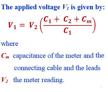
14 Objective: Measuring high A.C voltage using capacitive voltage dividers Components: An electrostatic voltmeter or a high impedance V.T.V.M. (vacuum-tube voltmeter) or an oscilloscope A standard compressed air or gas condenser, C 1 A large loss condenser (mica, paper,..). C 2 A long cable for connecting the HV source to the meter Wiring: as shown in Fig. 3.7 Procedure: Capacitance Potential Dividers 14
15 Capacitance Potential Dividers Procedure: Measure the value of C m Read the values of C 1 and C 2 Take the required H.V. measurement cautions Wire the circuit components as shown in Figure Connect the H.V. source to the connected circuit Read the voltmeter reading V 2 Calculate the Value of V 1 using Repeat the experiment and take the average 15
16 16
17 Capacitance Voltage Transformer - CVT It is similar to series capacitance voltmeter A matching transformer is connected between the load or meter M and C 2 The value of the tuning choke L is chosen to make the equivalent circuit of the CVT purely resistive or to bring resonance condition: L= inductance of the choke, L T = equivalent inductance of the transformer referred to h.v. side. 17
18 Capacitance Voltage Transformer - CVT The voltage ratio becomes: (neglecting the voltage drop I m X e which is very small compared to the voltage V C1 ) where V Ri is the voltage drop in the transformer and choke windings Prof. Dr. Magdi El-Saadawi 18
19 Capacitance Voltage Transformer - CVT The advantages of a CVT are: simple design and easy installation, can be used both as a voltage measuring device for meter and relaying purposes. frequency independent voltage distribution along elements as against conventional magnetic potential transformers which require additional insulation design against surges, and provides isolation between the high voltage terminal and low voltage metering. The disadvantages of a CVT are: the voltage ratio is susceptible to temperature variations, and the problem of inducing ferro-resonance in power systems. Prof. Dr. Magdi El-Saadawi 19
20 3.3.5 Spark Gaps A uniform field spark gap will always have a spark over voltage within a known tolerance under constant atmospheric conditions. Hence a spark gap can be used for measurement of the peak value of the voltage, if the gap distance is known. Normally, only sphere gaps are used for voltage measurements. In certain cases, uniform field gaps and rod gaps are also used, but their accuracy is less Sphere gap breakdown is independent of the voltage waveform and hence is suitable for measuring the peak value of all H.V. types: d.c., a.c. and impulse voltages of short rise times (rise time > 0.5 μs). 20
21 3.3.5 Spark Gaps Sphere gaps can be arranged either Vertically with lower sphere grounded, or horizontally with both spheres connected to the source voltage or one sphere grounded. The two spheres used are identical in size and shape. Spheres are generally made of copper, brass, or aluminum; the latter is used due to low cost. One sphere is grounded and the other is connected to the HV source A series resistance is usually connected between the source and the sphere gap to: limit the breakdown current The standard diameters for the spheres are as shown in 10/28/ tables: 2,5,6.25,10,12.5,15,25,50,75,100,150, and 200 cm.
22 22
23 23
24 3.3.5 Spark Gaps Procedure: The voltage to be measured is applied to the sphere The distance or spacing S between them is decreased until the spark occur Ground the spheres to discharge the electrical charges Take the distance S between spheres and compute the value of the measured voltage from the tables Repeat the experiment and take the average 24
25 25
26 26
27 Factors Influencing the Sparkover Voltage of Sphere Gaps nearby earthed objects, atmospheric conditions and humidity, irradiation, and polarity and rise time of voltage waveforms. 27
28 (i) Effect of nearby earthed objects 28
29 (ii) Effect of atmospheric conditions Humidity effect increases with the size of spheres and is maximum for uniform field gaps, and Sparkover voltage increases with the partial pressure of water vapor in air, and for a given humidity condition, the change in sparkover voltage increases with the gap length.
30 (iii) Effect of Irradiation Illumination of sphere gaps with ultra-violet or x- rays aids ionization in gaps easy. يساعد فى تسهيل عمليات التأين The effect of irradiation is pronounced واضح for small gap spacings. Hence, irradiation is necessary for smaller sphere gaps of gap spacing less than 1 cm for obtaining consistent values. 30
31 (iv) Effect of polarity and waveform It has been observed that the sparkover voltages for positive and negative polarity impulses are different. Experimental investigation showed that for sphere gaps of 6.25 to 25 cm diameter, the difference between positive and negative d.c. voltages is not more than 1%. For smaller sphere gaps (2 cm diameter and less) the difference was about 8% between negative and positive impulses of 1/50 μs waveform. 31
32 Rod Gaps A rod gap may be used to measure the peak value of power frequency and impulse voltages. The gap usually consists of two 1.27 cm square rod electrodes square in section at their end and are mounted on insulating stands so that a length of rod equal to or greater than one half of the gap spacing overhangs the inner edge of the support. The arrangement consists of two hemispherically capped rods of about 20 mm diameter as shown in Fig The accuracy of the above relation is better than 20% and, therefore, provides better accuracy even as compared to a sphere gap. 32
33 33
34 Video Links
9. How is an electric field is measured?
 UNIT IV - MEASUREMENT OF HIGH VOLTAGES AND HIGH CURRENTS PART-A 1. Mention the techniques used in impulse current measurements. Hall generators, Faraday generators and current transformers. 2.Mention the
DEPARTMENT OF ELECTRICAL ENGINEERING DIT UNIVERSITY EHV AC AND DC TRANSMISSION
 Generation of High A.. Voltages: Most of the present day transmission and distribution networks are operating on a.c. voltages and hence most of the testing equipment relate to high a.c. voltages. A single
ROEVER ENGINEERING COLLEGE ELAMBALUR, PERAMBALUR DEPARTMENT OF ELECTRICAL & ELECTRONICS ENGINEERING
 ROEVER ENGINEERING COLLEGE ELAMBALUR, PERAMBALUR 621 212 DEPARTMENT OF ELECTRICAL & ELECTRONICS ENGINEERING EE1003 HIGH VOLTAGE ENGINEERING QUESTION BANK UNIT-I OVER VOLTAGES IN ELECTRICAL POWER SYSTEM
PANIMALAR ENGINEERING COLLEGE Department of Electrical and Electronics Engineering
 PANIMALAR ENGINEERING COLLEGE Department of Electrical and Electronics Engineering 1. Write some applications of high voltage? High Voltage Engineering 2 mark Question with answers Unit I Overvoltages
HIGH VOLTAGE ENGINEERING(FEEE6402) LECTURER-24
 LECTURER-24") LECTURER-24 GENERATION OF HIGH ALTERNATING VOLTAGES When test voltage requirements are less than about 300kV, a single transformer can be used for test purposes. The impedance of the transformer should
LECTURER-24 GENERATION OF HIGH ALTERNATING VOLTAGES When test voltage requirements are less than about 300kV, a single transformer can be used for test purposes. The impedance of the transformer should
7.1 MEASUREMENT OF HIGH DIRECT CURRENT VOLTAGES
 7 Measurement of High Voltages and Currents In industrial testing and research laboratories, it is essential to measure the voltages and currents accurately, ensuring perfect safety to the personnel and
Lecture 36 Measurements of High Voltages (cont) (Refer Slide Time: 00:14)
 (Refer Slide Time: 00:14)") Advances in UHV Transmission and Distribution Prof. B Subba Reddy Department of High Voltage Engg (Electrical Engineering) Indian Institute of Science, Bangalore Lecture 36 Measurements of High Voltages
Advances in UHV Transmission and Distribution Prof. B Subba Reddy Department of High Voltage Engg (Electrical Engineering) Indian Institute of Science, Bangalore Lecture 36 Measurements of High Voltages
EE High Voltage Engineering UNIT IV - MEASUREMENT OF HIGH VOLTAGES AND HIGH CURRENTS PART-A 1. Mention the techniques used in impulse current
 EE6701 - High Voltage Engineering UNIT IV - MEASUREMENT OF HIGH VOLTAGES AND HIGH CURRENTS PART-A 1. Mention the techniques used in impulse current measurements. Hall generators, Faraday generators and
DEPARTMENT OF ELECTRICAL AND ELECTRONICS ENGINEERING QUESTION BANK SUBJECT CODE & NAME : EE 1402 HIGH VOLTAGE ENGINEERING UNIT I
 DEPARTMENT OF ELECTRICAL AND ELECTRONICS ENGINEERING QUESTION BANK SUBJECT CODE & NAME : EE 1402 HIGH VOLTAGE ENGINEERING YEAR / SEM : IV / VII UNIT I OVER VOLTAGES IN ELECTRICAL POWER SYSTEMS 1. What
3.2 Measurement of high voltages
 DEPT OF HIGH VOLTAGE AND INSULATION ENG, HONGQING UNIVERSITY Part I- hapter 3: Insulation test techniques 3. Measurement of high voltages Instructor: Dr. Jian Li Lecture 7- DEPT OF HIGH VOLTAGE AND INSULATION
FGJTCFWP"KPUVKVWVG"QH"VGEJPQNQI[" FGRCTVOGPV"QH"GNGEVTKECN"GPIKPGGTKPI" VGG"246"JKIJ"XQNVCIG"GPIKPGGTKPI
 FGJTFWP"KPUKWG"QH"GEJPQNQI[" FGRTOGP"QH"GNGETKEN"GPIKPGGTKPI" GG"46"JKIJ"XQNIG"GPIKPGGTKPI Resonant Transformers: The fig. (b) shows the equivalent circuit of a high voltage testing transformer (shown
High-Voltage Test Techniques
 High-Voltage Test Techniques Dieter Kind Kurt Feser 2nd Revised and Enlarged Edition With 211 Figures and 12 Laboratory Experiments Translated from the German by Y. Narayana Rao Professor of Electrical
MAHALAKSHMI ENGINEERING COLLEGE
 MAHALAKSHMI ENGINEERING COLLEGE TIRUCHIRAPALLI 621213 QUESTION BANK -------------------------------------------------------------------------------------------------------------- Sub. Code : EE2353 Semester
RESONANT TRANSFORMER
 RESONANT TRANSFORMER Whenever the requirement of the test voltage is too much high, a single unit transformer can not produce such high voltage very economically, because for high voltage measurement,
HV Module Systems for Testing, Training and Research
 HV Module Systems for Testing, Training and Research 4.0/3 Application Advantages Principle of HV circuit Smaller high-voltage (HV) test systems are necessary for research, development and quality testing
Power Engineering II. High Voltage Testing
 High Voltage Testing HV Test Laboratories Voltage levels of transmission systems increase with the rise of transmitted power. Long-distance transmissions are often arranged by HVDC systems. However, a
Generation of Sub-nanosecond Pulses
 Chapter - 6 Generation of Sub-nanosecond Pulses 6.1 Introduction principle of peaking circuit In certain applications like high power microwaves (HPM), pulsed laser drivers, etc., very fast rise times
High Voltage Engineering
 High Voltage Engineering Course Code: EE 2316 Prof. Dr. Magdi M. El-Saadawi www.saadawi1.net E-mail : saadawi1@gmail.com www.facebook.com/magdi.saadawi 9/23/2017 Prof. Dr. Magdi El-Saadawi 1 Contents Chapter
High Voltage Generation
 High Voltage Generation Purposes (Manfaat) Company Logo High DC High AC Impulse Electron microscopes and x-ray units (high d.c. voltages 100 kv) Electrostatic precipitators, particle accelerators (few
CHAPTER 2. v-t CHARACTERISTICS FOR STANDARD IMPULSE VOLTAGES
 23 CHAPTER 2 v-t CHARACTERISTICS FOR STANDARD IMPULSE VOLTAGES 2.1 INTRODUCTION For reliable design of power system, proper insulation coordination among the power system equipment is necessary. Insulation
AP Physics C. Alternating Current. Chapter Problems. Sources of Alternating EMF
 AP Physics C Alternating Current Chapter Problems Sources of Alternating EMF 1. A 10 cm diameter loop of wire is oriented perpendicular to a 2.5 T magnetic field. What is the magnetic flux through the
Appendix B Experimental equipment and procedures
 2 4 Appendix B Experimental equipment and procedures B.1 Spark generator details The detailed schematic layout for generation of high-voltage pulses used in the spark generator described in [29] is shown
University of Jordan School of Engineering Electrical Engineering Department. EE 219 Electrical Circuits Lab
 University of Jordan School of Engineering Electrical Engineering Department EE 219 Electrical Circuits Lab EXPERIMENT 4 TRANSIENT ANALYSIS Prepared by: Dr. Mohammed Hawa EXPERIMENT 4 TRANSIENT ANALYSIS
Design and construction of double-blumlein HV pulse power supply
 Sādhan ā, Vol. 26, Part 5, October 2001, pp. 475 484. Printed in India Design and construction of double-blumlein HV pulse power supply DEEPAK K GUPTA and P I JOHN Institute for Plasma Research, Bhat,
ELECTRICAL MEASUREMENTS
 R10 Set No: 1 1. a) Derive the expression for torque equation for a moving iron attraction type instrument and comment up on the nature of scale [8] b) Define the terms current sensitivity, voltage sensitivity
6 - Stage Marx Generator
 6 - Stage Marx Generator Specifications - 6-stage Marx generator has two capacitors per stage for the total of twelve capacitors - Each capacitor has 90 nf with the rating of 75 kv - Charging voltage used
Design and Implementation of 8 - Stage Marx Generator Used for Gas Lasers
 Design and Implementation of 8 - Stage Marx Generator Used for Gas Lasers Dr. Naseer Mahdi Hadi Ministry of Science & Technology, Laser & Electro-Optics Research Center, Baghdad, Iraq. Dr. Kadhim Abid
GUJARAT TECHNOLOGICAL UNIVERSITY
 GUJARAT TECHNOLOGICAL UNIVERSITY POWER ELECTRONICS (24) HIGH VOLTAGE ENGINEERING SUBJECT CODE: 2162411 BE 6 th SEMESTER Type of Course: Engineering Science (Electrical) Prerequisite: NA Rationale: The
Design and Fabrication of Tesla Coil
 Design and Fabrication of Tesla Coil Prof. S. M. Shaikh 1, Mr. Harshad Dube 2, Mrs. Sushmita Walunj 3, Mrs. Namita Thorat 4, 1 Assistant Professor, Electrical Engineering, AISSMS s IOIT, Maharashtra, India
Power Frequency Withstand Voltage On-site testing of 400 kv GIS
 Power Frequency Withstand Voltage On-site testing of 400 kv GIS D. Anaraki Ardakani, A. Omidkhoda, M. Solati High Voltage Engineering Center ACECR Tehran, Iran Da_ardakani@yahoo.com Paper Reference Number:
LESSON PLAN LP-EE Sub Code: EE 2353 Sub Name: HIGH VOLTAGE ENGINEERING Unit: I Branch: EEE Semester: VI
 Unit: I Branch: EEE Semester: VI Page 1 of 6 OVER VOLTAGES IN ELECTRICAL POWER SYSTEMS Causes of over voltages and its effect on power system Lightning, switching surges and temporary over voltages - protection
High Votage Module AC/DC/Impulse Test System
 TSGADI Series High Votage Module AC/DC/Impulse Test System A digital control and measuring system is used to be control the difference output AC/DC/Impulse and related protection device such as over voltage
Level 3 Physics, 2018
 91526 915260 3SUPERVISOR S Level 3 Physics, 2018 91526 Demonstrate understanding of electrical systems 2.00 p.m. Tuesday 20 November 2018 Credits: Six Achievement Achievement with Merit Achievement with
Methods of secondary short circuit current control in single phase transformers
 2015; 1(8): 412-417 ISSN Print: 2394-7500 ISSN Online: 2394-5869 Impact Factor: 5.2 IJAR 2015; 1(8): 412-417 www.allresearchjournal.com Received: 17-05-2015 Accepted: 20-06-2015 Parantap Nandi A/2, Building
Error vs. Uncertainty Historical Perspective
 1 Error vs. Uncertainty Historical Perspective Jim McBride Chairman PSIM Committee Vice-Chairman HVTT Subcommittee IEEE PES SPDC Fall 2017 Clearwater, FL Discussions on Uncertainty PSIM - HVTT Subcommittee
Electronic Measurements & Instrumentation. 1. Draw the Maxwell s Bridge Circuit and derives the expression for the unknown element at balance?
 UNIT -6 1. Draw the Maxwell s Bridge Circuit and derives the expression for the unknown element at balance? Ans: Maxwell's bridge, shown in Fig. 1.1, measures an unknown inductance in of standard arm offers
Coherence and time-frequency analysis of impulse voltage and current measurements
 Coherence and time-frequency analysis of impulse voltage and current measurements Jelena Dikun Electrical Engineering Department, Klaipeda University, Klaipeda, Lithuania Emel Onal Electrical Engineering
EE 1402 HIGH VOLTAGE ENGINEERING
 EE 1402 HIGH VOLTAGE ENGINEERING Unit 5 TESTS OF INSULATORS Type Test To Check The Design Features Routine Test To Check The Quality Of The Individual Test Piece. High Voltage Tests Include (i) Power frequency
Zaran make 25 cm sphere gap set (vertical type) with remote control unit, and kv test transformer along with control unit.
 with remote control unit, and kv test transformer along with control unit.") A ', ~'" -,.." 'b" /,u;1'f r ~. f. r ". k,..." 'C t \ V (' H "J (. "POY c;(> A ~~,f' Gap with one sphere earthed anq to verify the empirical relationship with the result given in standard table, o To study
A ', ~'" -,.." 'b" /,u;1'f r ~. f. r ". k,..." 'C t \ V (' H "J (. "POY c;(> A ~~,f' Gap with one sphere earthed anq to verify the empirical relationship with the result given in standard table, o To study
BARINGO COUNTY EDUCATIONALIMPROVEMENT EXAMINATION Kenya Certificate of Secondary Education
 NAME: INDEX NO. ADM NO... 232/2 Signature: PHYSICS PAPER 2 JULY/ AUGUST 2011 Date: TIME: 2 HRS. BARINGO COUNTY EDUCATIONALIMPROVEMENT EXAMINATION Kenya Certificate of Secondary Education INSTRUCTIONS TO
Over-voltage Trigger Device for Marx Generators
 Journal of the Korean Physical Society, Vol. 59, No. 6, December 2011, pp. 3602 3607 Over-voltage Trigger Device for Marx Generators M. Sack, R. Stängle and G. Müller Karlsruhe Institute of Technology
CHAPTER 15 GROUNDING REQUIREMENTS FOR ELECTRICAL EQUIPMENT
 CHAPTER 15 GROUNDING REQUIREMENTS FOR ELECTRICAL EQUIPMENT A. General In a hazardous location grounding of an electrical power system and bonding of enclosures of circuits and electrical equipment in the
Prepared by Mick Maytum
 IEC Technical Committee 109: Standards on insulation co-ordination for low-voltage equipment Warning Prepared by Mick Maytum mjmaytum@gmail.com The document content is of a general nature only and is not
ELECTROMAGNETIC INDUCTION AND ALTERNATING CURRENT (Assignment)
") ELECTROMAGNETIC INDUCTION AND ALTERNATING CURRENT (Assignment) 1. In an A.C. circuit A ; the current leads the voltage by 30 0 and in circuit B, the current lags behind the voltage by 30 0. What is the
ELECTROMAGNETIC INDUCTION AND ALTERNATING CURRENT (Assignment) 1. In an A.C. circuit A ; the current leads the voltage by 30 0 and in circuit B, the current lags behind the voltage by 30 0. What is the
LS200 TEST DATA IEC61000 SERIES
 TEST DATA IEC61000 SERIES DWG. No. PA607-58-01 APPD CHK DWG TDK-Lambda INDEX LS200 PAGE 1. Electrostatic Discharge Immunity Test (IEC61000-4-2) R-1 2. Radiated Radio-Frequency Electromagnetic Field Immunity
A Self-balanced, Liquid Resistive, High Impedance HV Divider
 A Self-balanced, Liquid Resistive, High Impedance HV Divider M. Denicolai * and J. Hällström Helsinki University of Technology, Power Systems and High Voltage Engineering, PL, 25 TKK, Finland * E-mail:
ELECTRONICS AND ELECTRICITY
 INTRODUCTION ELECTRONICS ND ELECTRICITY The science of Electronics and Electricity makes a very important contribution to our everyday existence. Electricity is concerned with the generation, transmission
Chapter 11. Alternating Current
 Unit-2 ECE131 BEEE Chapter 11 Alternating Current Objectives After completing this chapter, you will be able to: Describe how an AC voltage is produced with an AC generator (alternator) Define alternation,
10. DISTURBANCE VOLTAGE WITHSTAND CAPABILITY
 9. INTRODUCTION Control Cabling The protection and control equipment in power plants and substations is influenced by various of environmental conditions. One of the most significant environmental factor
what is a multiplier? how does a multiplier work? common multiplier applications II. Assembly Type III. Other Design Concerns
 SECTION 13 Multipliers VMI manufactures many high voltage multipliers, most of which are custom designed for specific requirements. The following information provides general information and basic guidance
UNIT V - RECTIFIERS AND POWER SUPPLIES
 UNIT V - RECTIFIERS AND POWER SUPPLIES OBJECTIVE On the completion of this unit the student will understand CLASSIFICATION OF POWER SUPPLY HALF WAVE, FULL WAVE, BRIDGE RECTIFER AND ITS RIPPLE FACTOR C,
Chapter 21. Alternating Current Circuits and Electromagnetic Waves
 Chapter 21 Alternating Current Circuits and Electromagnetic Waves AC Circuit An AC circuit consists of a combination of circuit elements and an AC generator or source The output of an AC generator is sinusoidal
86 chapter 2 Transformers
 86 chapter 2 Transformers Wb 1.2x10 3 0 1/60 2/60 3/60 4/60 5/60 6/60 t (sec) 1.2x10 3 FIGURE P2.2 2.3 A single-phase transformer has 800 turns on the primary winding and 400 turns on the secondary winding.
University of Jordan School of Engineering Electrical Engineering Department. EE 219 Electrical Circuits Lab
 University of Jordan School of Engineering Electrical Engineering Department EE 219 Electrical Circuits Lab EXPERIMENT 7 RESONANCE Prepared by: Dr. Mohammed Hawa EXPERIMENT 7 RESONANCE OBJECTIVE This experiment
Technical Specification
 LARGEST RANGE OF IMPULSE TESTERS UP TO 100KV/100KA Technical Specification E-MIG1203CWG revised: 22. June 2003 1 MIG Tester Type MIG1203CWG 1 MIG Tester Type MIG1203CWG 1 1.1 Introduction 1 2 General 2
1. General Instructions 2 2. Safety 2 3. Lamp Starting Test Instrument LSTI 5 3
 1. General Instructions 2 2. Safety 2 3. Lamp Starting Test Instrument LSTI 5 3 3.1. Components and Connections of the Front Panel (Fig. 1) 5 3.2. Connection of the Rear Panel (Fig. 2) 7 3.3. Operation
DISTRIBUTION STATEMENT A Approved for Public Release Distribution Unlimited. Serial No.: 09/ Filing Date: 08 February 2001 NOTICE
 Serial No.: 09/778.950 Filing Date: 08 February 2001 Inventor: John F. Sealy NOTICE The above identified patent application is available for licensing. Requests for information should be addressed to:
Type 297, High-Voltage Mica Capacitors Corona-free Mica Coupling Capacitors for Medium-Voltage PDA s
 Designed for Partial Discharge Analyzers (PDA s) monitoring rotating machinery or other medium-voltage equipment from 1 to 35 kvac RMS at power-line frequencies of 10 Hz to 1 khz, Mica Capacitor Type 297
AMENDMENT NO. 1 SEPTEMBER IS (Part 1) : 2001/IEC (1991) SURGE ARRESTORS
 : 2001/IEC (1991) SURGE ARRESTORS") AMENDMENT NO. 1 SEPTEMBER 2011 TO IS 15086 (Part 1) : 2001/IEC 60099-1 (1991) SURGE ARRESTORS PART 1 NON-LINEAR RESISTOR TYPE GAPPED SURGE ARRESTORS FOR a.c. SYSTEMS (The Amendment was originally published
AMENDMENT NO. 1 SEPTEMBER 2011 TO IS 15086 (Part 1) : 2001/IEC 60099-1 (1991) SURGE ARRESTORS PART 1 NON-LINEAR RESISTOR TYPE GAPPED SURGE ARRESTORS FOR a.c. SYSTEMS (The Amendment was originally published
MEASUREMENT OF THE INTERNAL INDUCTANCE OF IMPULSE VOLTAGE GENERATORS AND THE LIMITS OF LI FRONT TIMES
 The 20 th International Symposium on High Voltage Engineering, Buenos Aires, Argentina, August 27 September 01, 2017 MEASUREMENT OF THE INTERNAL INDUCTANCE OF IMPULSE VOLTAGE GENERATORS AND THE LIMITS
Testing 320 kv HVDC XLPE Cable System
 Testing 320 kv HVDC XLPE Cable System H. He, W. Sloot DNV GL, KEMA Laboratories Arnhem, The Netherlands Abstract Two unique test requirements in testing of a high- voltage direct- current (HVDC) cable
Visualization of the Ionization Phenomenon in Porous Materials under Lightning Impulse
 Visualization of the Ionization Phenomenon in Porous Materials under Lightning Impulse A. Elzowawi, A. Haddad, H. Griffiths Abstract the electric discharge and soil ionization phenomena have a great effect
GRID CONTROLLED POWER SUPPLY IS A VERSATILE UNIT Uses Pair of RCA-2050 s for Wide Voltage Range
 10/30/07 11:55 PM Thyratrons GRID CONTROLLED POWER SUPPLY IS A VERSATILE UNIT Uses Pair of RCA-2050 s for Wide Voltage Range By J. H. OWENS, W2FTW and G. D. HANCHETT, W1AK/2 RCA Ham Tips Volume 6, Number
Lab E5: Filters and Complex Impedance
 E5.1 Lab E5: Filters and Complex Impedance Note: It is strongly recommended that you complete lab E4: Capacitors and the RC Circuit before performing this experiment. Introduction Ohm s law, a well known
Impulse testing of coils and magnets: present experience and future plans
 Impulse testing of coils and magnets: present experience and future plans M. Marchevsky, E. Ravaioli, LBNL G. Ambrosio, FNAL M. Marchevsky 1 Impulse testing for LARP magnets Impulse testing is a key electrical
A 1.1 MV REP-RATE IN-LINE OUTPUT SWITCH AND TRIGGERING SYSTEM
 A 1.1 MV REP-RATE IN-LINE OUTPUT SWITCH AND TRIGGERING SYSTEM A. Ramrus, G. Rohwein, H. Fleming Applied Pulse Technology, Inc. 3663 Syracuse Court San Diego, California 92122 K. Hendricks *, D. Shiffler
RAP Ripple Control Coupling for parallel injection of RC signals in Medium and High Voltage Networks
 RAP Ripple Control Coupling for parallel injection of RC signals in Medium and High Voltage Networks We reserve all rights to this document, and the subject-matter it deals with. Duplication, dissemination
148 Electric Machines
 148 Electric Machines 3.1 The emf per turn for a single-phase 2200/220- V, 50-Hz transformer is approximately 12 V. Calculate (a) the number of primary and secondary turns, and (b) the net cross-sectional
14. Card Test Methods
 14. Card Test Methods This section specifies the PICC test methods specified with ISO/IEC 10373-6, while also specifying the test method of PICC in consideration of the characteristics and so forth of
Class XII Chapter 7 Alternating Current Physics
 Question 7.1: A 100 Ω resistor is connected to a 220 V, 50 Hz ac supply. (a) What is the rms value of current in the circuit? (b) What is the net power consumed over a full cycle? Resistance of the resistor,
THE MOMBASA POLYTECHNIC UNIVERSITY COLLEGE
 THE MOMBASA POLYTECHNIC UNIVERSITY COLLEGE Faculty of Engineering and Technology DEPARTMENT OF ELECTRICAL & ELECTRONIC ENGINEERING DIPLOMA IN TECHNOLOGY Electrical Power Engineering Instrumentation & Control
5. Transducers Definition and General Concept of Transducer Classification of Transducers
 5.1. Definition and General Concept of Definition The transducer is a device which converts one form of energy into another form. Examples: Mechanical transducer and Electrical transducer Electrical A
CDAX 605 High Precision Capacitance & Dissipation Factor Test Set
 CDAX 605 High Precision Capacitance & Dissipation Factor Test Set 1 Tan delta and capacitance measurements Hi V A Lo Ground C HL Measure with AC test signal, use Ohms law to calculate: Dissipation factor
An induced emf is the negative of a changing magnetic field. Similarly, a self-induced emf would be found by
 This is a study guide for Exam 4. You are expected to understand and be able to answer mathematical questions on the following topics. Chapter 32 Self-Induction and Induction While a battery creates an
CURRENT ELECTRICITY. 1. The S.I. unit of power is (a) Henry (b) coulomb (c) watt (d) watt-hour Ans: c
 Henry (b) coulomb (c) watt (d) watt-hour Ans: c") CURRENT ELECTRICITY 1. The S.I. unit of power is (a) Henry (b) coulomb (c) watt (d) watt-hour 2. Electric pressure is also called (a) resistance (b) power (c) voltage (d) energy 3. The substances which
CURRENT ELECTRICITY 1. The S.I. unit of power is (a) Henry (b) coulomb (c) watt (d) watt-hour 2. Electric pressure is also called (a) resistance (b) power (c) voltage (d) energy 3. The substances which
SF 6 Capacitive Voltage Divider
 SF 6 Capacitive oltage Divider Cattareeya Suwanasri and Thanapong Suwanasri Abstract This paper aims to develop a 100 k capacitive voltage divider. The divider was separated into high voltage and low voltage
1. (a) Determine the value of Resistance R and current in each branch when the total current taken by the curcuit in figure 1a is 6 Amps.
 Determine the value of Resistance R and current in each branch when the total current taken by the curcuit in figure 1a is 6 Amps.") Code No: 07A3EC01 Set No. 1 II B.Tech I Semester Regular Examinations, November 2008 ELECTRICAL AND ELECTRONICS ENGINEERING ( Common to Civil Engineering, Mechanical Engineering, Mechatronics, Production
Code No: 07A3EC01 Set No. 1 II B.Tech I Semester Regular Examinations, November 2008 ELECTRICAL AND ELECTRONICS ENGINEERING ( Common to Civil Engineering, Mechanical Engineering, Mechatronics, Production
Design, Construction and Optimization of Tesla Coil
 Design, Construction and Optimization of Tesla Coil El-Aragi GM * Plasma Physics and Nuclear Fusion Department, Nuclear Research Center, Cairo, Egypt * Corresponding author: El-Aragi GM, Plasma Physics
Condition Assessment of High Voltage Insulation in Power System Equipment. R.E. James and Q. Su. The Institution of Engineering and Technology
 Condition Assessment of High Voltage Insulation in Power System Equipment R.E. James and Q. Su The Institution of Engineering and Technology Contents Preface xi 1 Introduction 1 1.1 Interconnection of
Pre-Laboratory Assignment
 Measurement of Electrical Resistance and Ohm's Law PreLaboratory Assignment Read carefully the entire description of the laboratory and answer the following questions based upon the material contained
Design and performance analysis of transmission line-based nanosecond pulse multiplier
 Sādhanā Vol. 31, Part 5, October 2006, pp. 597 611. Printed in India Design and performance analysis of transmission line-based nanosecond pulse multiplier RISHI VERMA, A SHYAM and KUNAL G SHAH Institute
UNIVERSITY OF TECHNOLOGY, JAMAICA SCHOOL OF ENGENEERING. Electrical Engineering Science. Laboratory Manual
 UNIVERSITY OF TECHNOLOGY, JAMAICA SCHOOL OF ENGENEERING Electrical Engineering Science Laboratory Manual Table of Contents Experiment #1 OHM S LAW... 3 Experiment # 2 SERIES AND PARALLEL CIRCUITS... 8
Design and Construction of a150kv/300a/1µs Blumlein Pulser
 Design and Construction of a150kv/300a/1µs Blumlein Pulser J.O. ROSSI, M. UEDA and J.J. BARROSO Associated Plasma Laboratory National Institute for Space Research Av. dos Astronautas 1758, São José dos
Electromagnetic Oscillations and Currents. March 23, 2014 Chapter 30 1
 Electromagnetic Oscillations and Currents March 23, 2014 Chapter 30 1 Driven LC Circuit! The voltage V can be thought of as the projection of the vertical axis of the phasor V m representing the time-varying
Power Quality. Case Study. Conrad Bottu Laborelec January 2008
 Case Study Electromagnetic compatibility (EMC) study Breakdown of low voltage electronic equipment in a 25 kv substation Conrad Bottu Laborelec January 2008 Power Quality Power Quality 1 Introduction Description
Radar. Radio. Electronics. Television. .104f 4E011 UNITED ELECTRONICS LABORATORIES LOUISVILLE
 Electronics Radio Television.104f Radar UNITED ELECTRONICS LABORATORIES LOUISVILLE KENTUCKY REVISED 1967 4E011 1:1111E111611 COPYRIGHT 1956 UNITED ELECTRONICS LABORATORIES POWER SUPPLIES ASSIGNMENT 23
Analysis of lightning performance of 132KV transmission line by application of surge arresters
 Analysis of lightning performance of 132KV transmission line by application of surge arresters S. Mohajer yami *, A. Shayegani akmal, A.Mohseni, A.Majzoobi High Voltage Institute,Tehran University,Iran
INSTITUTE OF AERONAUTICAL ENGINEERING Dundigal, Hyderabad
 Course Name Course Code Class Branch INSTITUTE OF AERONAUTICAL ENGINEERING Dundigal, Hyderabad -500 043 AERONAUTICAL ENGINEERING TUTORIAL QUESTION BANK : ELECTRICAL AND ELECTRONICS ENGINEERING : A40203
EE 241 Experiment #4: USE OF BASIC ELECTRONIC MEASURING INSTRUMENTS, Part III 1
 EE 241 Experiment #4: USE OF BASIC ELECTRONIC MEASURING INSTRUMENTS, Part III 1 PURPOSE: To become familiar with more of the instruments in the laboratory. To become aware of operating limitations of input
Physics for Scientists & Engineers 2 2 = 1 LC. Review ( ) Review (2) Review (3) e! Rt. cos "t + # ( ) q = q max. Spring Semester 2005 Lecture 30 U E
 Review (2) Review (3) e! Rt. cos t + # ( ) q = q max. Spring Semester 2005 Lecture 30 U E") Review hysics for Scientists & Engineers Spring Semester 005 Lecture 30! If we have a single loop RLC circuit, the charge in the circuit as a function of time is given by! Where q = q max e! Rt L cos "t
Review hysics for Scientists & Engineers Spring Semester 005 Lecture 30! If we have a single loop RLC circuit, the charge in the circuit as a function of time is given by! Where q = q max e! Rt L cos "t
Fatima Michael college of Engineering and Technology
 Fatima Michael college of Engineering and Technology DEPARTMENT OF ELECTRICAL AND ELECTRONICS ENGINEERING EE2303 TRANSMISSION AND DISTRIBUTION SEM: V Question bank UNIT I INTRODUCTION 1. What is the electric
List of Experiments. Exp. # Experiment Title Page #
 List of Experiments Exp. # Experiment Title Page # -- Safety Rules 02 1 Study of High Lab in the University 03 2 To Calibrate a Sphere-Gap using its Breakdown Strength against Gap Settings 07 3 To Calibrate
Sine waves by far the most important form of alternating quantity important properties are shown below
 AC DC METERS 1 Sine waves by far the most important form of alternating quantity important properties are shown below 2 Average value of a sine wave average value over one (or more) cycles is clearly zero
A Low Impedance Marx Generator as a Test bed for Vacuum Diodes
 A Low Impedance Marx Generator as a Test bed for Vacuum Diodes Biswajit Adhikary, P Deb, R.Verma, R. Shukla, S.K.Sharma P.Banerjee, R Das, T Prabaharan, BK Das and Anurag Shyam Energetics and Electromagnetics
1. If the flux associated with a coil varies at the rate of 1 weber/min,the induced emf is
 1. f the flux associated with a coil varies at the rate of 1 weber/min,the induced emf is 1 1. 1V 2. V 60 3. 60V 4. Zero 2. Lenz s law is the consequence of the law of conservation of 1. Charge 2. Mass
Design and Simulation of Passive Filter
 Chapter 3 Design and Simulation of Passive Filter 3.1 Introduction Passive LC filters are conventionally used to suppress the harmonic distortion in power system. In general they consist of various shunt
University of Pennsylvania Moore School of Electrical Engineering ESE319 Electronic Circuits - Modeling and Measurement Techniques
 University of Pennsylvania Moore School of Electrical Engineering ESE319 Electronic Circuits - Modeling and Measurement Techniques 1. Introduction. Students are often frustrated in their attempts to execute
REQUIRED SKILLS AND KNOWLEDGE UEENEEE104A. Topic and Description NIDA Lesson CARD #
 REQUIRED SKILLS AND KNOWLEDGE UEENEEE104A KS01-EE104A Direct current circuits T1 Topic and Description NIDA Lesson CARD # Basic electrical concepts encompassing: electrotechnology industry static and current
Chapter 30 Inductance, Electromagnetic. Copyright 2009 Pearson Education, Inc.
 Chapter 30 Inductance, Electromagnetic Oscillations, and AC Circuits 30-7 AC Circuits with AC Source Resistors, capacitors, and inductors have different phase relationships between current and voltage
TT 0710/03. TYPE TEST OF 3 Phase Solid Earthing Bonding Link Box, Type: LB.W.3SA.3.1
 TT 0710/03 TYPE TEST OF 3 Phase Solid Earthing Bonding Link Box, Type: LB.W.3SA.3.1 Tested by: IPH, Berlin RPT No : 2977.2100555.0379 Date: 09 June to 24 June, 2010 Pages: 30 Appendix: --- TT0710.03 A3