Radio Frequency Electronics
|
|
|
- Clarissa Walker
- 5 years ago
- Views:
Transcription


1 Radio Frequency Electronics Frederick Emmons Terman Transformers Masters degree from Stanford and Ph.D. from MIT Later a professor at Stanford His students include William Hewlett and David Packard Wrote a very influential book Electronic and Radio Engineering, that is still referenced 60 years later During WWI, directed the Radio Research Lab at Harvard, directing a staff of more than 850 Became Dean of Engineering at Stanford Founding member of the National Academy of Engineering Dies in 1982 Image from Wikipedia 1

2 RC Parallel Series RC Summary Derived in class, make sure you can derive the corresponding series parallel transformation 2


3 LC Parallel Series LC Summary Derived in class, make sure you can derive the corresponding series parallel transformation 3

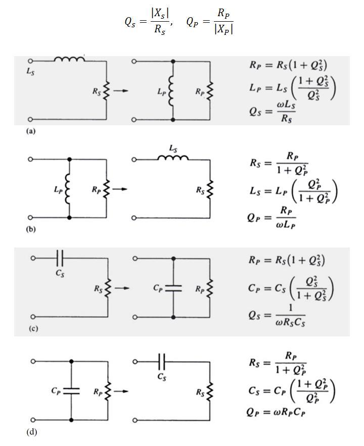
4 Summary of LC, RC Transformations 4
 is Q s = ωl = 2π 100 106 50 10 9 R s 10 = 3.14 Since Q s is low, we will not use the approximation R p Q s 2 R s. Rather R p = 1 + Q s 2 R s = 1 + 3.")
5 Example Example. Compute the Q of a 50 nh inductor with series resistance R s = 10 Ω at 100 MHz. Transform the circuit to an equivalent RL network. Solution. The Q of the inductor (and the network) is Q s = ωl = 2π R s 10 = 3.14 Since Q s is low, we will not use the approximation R p Q s 2 R s. Rather R p = 1 + Q s 2 R s = = 1,08.7 Ω L p = L s 1 + Q s 2 Q s 2 = = 55.1 nh Note how the reactive element transformed the100 Ω resistor to a Ω resistor. 5

6 Parallel LC circuit with Series Loss (C) Similar to the case of a parallel LC circuit with loss in series with L, for the case where the loss is in series with C, one can transform the circuit to a parallel RLC circuit. In this case, one will use a series parallel RC network transformation. Loss in series with C Equivalent RLC Transformation used Start with computing Q s Q s = 1 ωr s C s Then use Q s to compute C p and R p C p = C s Q s Q s 2 R p = R s 1 + Q s 2 6

7 Parallel LC with loss in both L and C 7

8 Impedance Matching In RF work, the input- and output impedances of the various building blocks are often a very important consideration. Receiver Antenna Amplifier Transmitter Antenna Z i Z o Z i Z o Very often the goal is to maximize the power transfer from one stage to another, and RF engineers concern them more with power gain than with voltage- or current gain. Z g V g P g Z i Z o Z L P L 8


9 Impedance Matching For maximum power transfer from a generator to a load, the load s input impedance must be the complex conjugate of the generator. Z g V g P g Z i Z o Z L P L For the block diagram above, to maximize P L P g, we should have Z g = Z i Z o = Z L To accomplish this, we insert impedance-matching blocks between stages Z g V g P g Z i Z o Z L P L Impedance matching network makes Z i = Z g Impedance matching network makes Z o = Z L 9

.")

10 Impedance Matching There are several method for impedance matching. If the load is purely resistive, then a traditional transformer can be used. This technique is popular in audio applications. One can model a moving-coil speakers as a small-value resistor (4 Ω, 8Ω). The output stage of the amplifier may want to see a large resistor. A transformer with a n: 1 turn ratio will transform the load resistance by a factor n 2. V cc n:1 Turns ratio 10 mm Dot convention R L Resistive Load Output transistor of power amplifier Small audio transformer A typical requirement would be transform an 8 Ω load to 600 Ω. This would require a turns ratio of = 8.66 or 8.66: 1. 10


11 Transformers for Impedance Matching Transformer Transformer Auto-transformer or tapped inductor High-pass L High-pass L Low-pass L Low-pass L Resonant capacitive transformer Capacitive transformer π Network Sections of transmission lines 11

 amplifiers.")


12 RF Transformers RF transformers are often tuned. That is, a capacitor is added that will resonate with the inductor. The were once widely-used in radios as part of the intermediate frequency (IF) amplifiers. Companies manufactured IF transformers and house them in small metal enclosures, which leads to the term IF can. Note the tapped inductor, which provides additional flexibility for impedance transformations Often these transformers have a ferrite slug that one can screw in or out to change the coupling between the windings Aluminum can provides electrical shielding as well as mechanical stability. 12


 Windings Tuning slug IF")
13 RF Transformers The intermediate frequency for AM radio normally 455 khz and companies developed a range of transformers for the frequency. Color coding indicate different transfer properties (transformer ratio, etc.) Windings Tuning slug IF Transformer Use of such transformers waning fast 13
, then we can approximate the voltage division ratio v o s v i s n where n = C 1 C 1 + C 2 v i s v o s /n where n = C 1 C 1 + C 2 14")
14 Capacitive Voltage Divider v o s = v i s 1 sc 2 1 sc sc 1 = v i s C 1 C 1 + C 2 v o s = v i s n where n = C 1 C 1 + C 2 In instances where there is a load in parallel with C 2 and the load is light (i.e., high- Q), then we can approximate the voltage division ratio v o s v i s n where n = C 1 C 1 + C 2 v i s v o s /n where n = C 1 C 1 + C 2 14
15 The Capacitive Transformer A very useful sub circuit is a capacitive transformer. It consist of a capacitive voltage divider with a load across one of the capacitors as shown in (a) below. Assuming Q is large, then one can transform the circuit using successive RC transformations to the circuit in (c). 15
16 The Capacitive Transformer On the previous slide we showed the following equivalency v i v 0 The equations suggest we can model the network as a transformer v i v o /n v i v i v 0 v 0 16
 of the equivalent parallel network is Q T = ωr p C p.")
17 The Capacitive Transformer We need to quantify by what we mean by large Q. Define Q E as the Q of the RC network which results network with the input shorted so that R sees C 1 and C 2 in parallel. That is, Q E = ωr C 1 + C 2. The network Q (i.e., Q T ) of the equivalent parallel network is Q T = ωr p C p. One can show that if nq T Q E > 20 then the approximation is within 5% and if nq T Q E > 100, the approximation very good. Model is good when nq T Q E > 20 Q E = ωr C 1 + C 2 Model is very good when nq T Q E >

 (b) n = C 1 C 1 + C 2 = 10 15 = 2 3 R p = 1K n 2 = 2.")

18 The Capacitive Transformer Example. Consider the capacitive voltage divider below and determine the parameters for the equivalent network shown in (b). Check the model assumptions at f = 100 khz. Solution (a) (b) n = C 1 C 1 + C 2 = = 2 3 R p = 1K n 2 = 2.25K C p = C 1C 2 C 1 + C 2 = = 3.33 nf Check assumptions Q E = ω C 1 + C 2 R L = 2π = 9.42 Q T = ωc p R P = 2π = 4.7 nq T Q E = = 29.6 > 20 Since nq T Q E > 20 the model is good, and R p is within 5% 18
19 Example. For the circuit below, determine L, C 1, and C 1 so that the circuit resonates at f 0 = 16 MHz with B = 1.06 MHz and achieves maximum power transfer to R L. L, C 1, C 2 are lossless. Solution We will assume that nq E Q T is large and replace the capacitive voltage divider with the ideal transformer model. At resonance the circuit is purely resistance. For maximum power transfer we want R s to equal the transformed R L. This determines the turns ratio (n) of our model: n = R L R s = 1K 9K = 1 3 = C 1 C 1 + C 2 The total input resistance the source sees is 9K 2 = 4.5K. Further, B = 1 RLC circuit, from with it follows that C = 1 B R and RC for a parallel C = C 1C 2 C 1 + C 2 = 1 (B)(R) = 1 2π = pf Since C 1 C 1 + C 2 = 1 3 we can solve for C 1 = 50 pf and C 2 = 100 pf. Further, since ω 0 = 1 LC, we can solve for L = 1 ω 2 0 C = 30 μh. Self-study: check that the model assumptions are valid. 19
 Solution. The network in (a) transforms to the network in (b) above. The Q T for (b) must be Q T = (100 MHz) 10 MHz = 10.")
 we have Q T = 10 = R ω 0 L R = 10 ω 0L Here R is the parallel combination of the source- and load resistances, and R p, namely (b) R = 10 ω 0 L = 500 R p 500 + R p 10 85R s")
20 Example. Design a resonant LC network so that BW is 10 MHz around 100 MHz. Both the sourceand load resistances are 1K. Assume inductors with Q = 85 and lossless capacitors are available. (a) Solution. The network in (a) transforms to the network in (b) above. The Q T for (b) must be Q T = (100 MHz) 10 MHz = 10. The Qs in the circuit is high, so we will use simplified formulas: R p = Q s 2 R s = 85 2 R s and L p = L s. Further, ω 0 L = 85R s. For the network in (b) we have Q T = 10 = R ω 0 L R = 10 ω 0L Here R is the parallel combination of the source- and load resistances, and R p, namely (b) R = 10 ω 0 L = 500 R p R p 10 85R s = R s R s R s = Ω From ω 0 L = 85R s it follows that L = nh, and from ω 0 = 1 LC it follows that C = 36 pf 20
21 More Transformers Capacitive transformer Inductive transformer Autotransformer Normal transformer 21

22 22
EE301 ELECTRONIC CIRCUITS CHAPTER 2 : OSCILLATORS. Lecturer : Engr. Muhammad Muizz Bin Mohd Nawawi
 EE301 ELECTRONIC CIRCUITS CHAPTER 2 : OSCILLATORS Lecturer : Engr. Muhammad Muizz Bin Mohd Nawawi 2.1 INTRODUCTION An electronic circuit which is designed to generate a periodic waveform continuously at
Homework Assignment 03
 Question (75 points) Homework Assignment 03 Overview Tuned Radio Frequency (TRF) receivers are some of the simplest type of radio receivers. They consist of a parallel RLC bandpass filter with bandwidth
Exercise 1: Series Resonant Circuits
 Series Resonance AC 2 Fundamentals Exercise 1: Series Resonant Circuits EXERCISE OBJECTIVE When you have completed this exercise, you will be able to compute the resonant frequency, total current, and
Homework Assignment 05
 Homework Assignment 05 Question (2 points each unless otherwise indicated)(20 points). Estimate the parallel parasitic capacitance of a mh inductor with an SRF of 220 khz. Answer: (2π)(220 0 3 ) = ( 0
CHAPTER 6: ALTERNATING CURRENT
 CHAPTER 6: ALTERNATING CURRENT PSPM II 2005/2006 NO. 12(C) 12. (c) An ac generator with rms voltage 240 V is connected to a RC circuit. The rms current in the circuit is 1.5 A and leads the voltage by
UNIT _ III MCQ. Ans : C. Ans : C. Ans : C
 UNIT _ III MCQ Ans : C Ans : C Ans : C Ans : A Ans : B Multiple Choice Questions and Answers on Transistor Tuned Amplifiers Q1. A tuned amplifier uses. load 1. Resistive 2. Capacitive 3. LC tank 4. Inductive
UNIVERSITY OF BABYLON BASIC OF ELECTRICAL ENGINEERING LECTURE NOTES. Resonance
 Resonance The resonant(or tuned) circuit, in one of its many forms, allows us to select a desired radio or television signal from the vast number of signals that are around us at any time. Resonant electronic
Class XII Chapter 7 Alternating Current Physics
 Question 7.1: A 100 Ω resistor is connected to a 220 V, 50 Hz ac supply. (a) What is the rms value of current in the circuit? (b) What is the net power consumed over a full cycle? Resistance of the resistor,
Radio Frequency Electronics
 Radio Frequency Electronics Preliminaries II Guglielmo Giovanni Maria Marconi Thought off by many people as the inventor of radio Pioneer in long-distance radio communications Shared Nobel Prize in 1909
Outcomes: Core Competencies for ECE145A/218A
 Outcomes: Core Competencies for ECE145A/18A 1. Transmission Lines and Lumped Components 1. Use S parameters and the Smith Chart for design of lumped element and distributed L matching networks. Able to
Chapter 2. The Fundamentals of Electronics: A Review
 Chapter 2 The Fundamentals of Electronics: A Review Topics Covered 2-1: Gain, Attenuation, and Decibels 2-2: Tuned Circuits 2-3: Filters 2-4: Fourier Theory 2-1: Gain, Attenuation, and Decibels Most circuits
Properties of Inductor and Applications
 LABORATORY Experiment 3 Properties of Inductor and Applications 1. Objectives To investigate the properties of inductor for different types of magnetic material To calculate the resonant frequency of a
CHAPTER 14. Introduction to Frequency Selective Circuits
 CHAPTER 14 Introduction to Frequency Selective Circuits Frequency-selective circuits Varying source frequency on circuit voltages and currents. The result of this analysis is the frequency response of
TUNED AMPLIFIERS 5.1 Introduction: Coil Losses:
 TUNED AMPLIFIERS 5.1 Introduction: To amplify the selective range of frequencies, the resistive load R C is replaced by a tuned circuit. The tuned circuit is capable of amplifying a signal over a narrow
Figure 1: Closed Loop System
 SIGNAL GENERATORS 3. Introduction Signal sources have a variety of applications including checking stage gain, frequency response, and alignment in receivers and in a wide range of other electronics equipment.
EE12: Laboratory Project (Part-2) AM Transmitter
 AM Transmitter") EE12: Laboratory Project (Part-2) AM Transmitter ECE Department, Tufts University Spring 2008 1 Objective This laboratory exercise is the second part of the EE12 project of building an AM transmitter in
EE12: Laboratory Project (Part-2) AM Transmitter ECE Department, Tufts University Spring 2008 1 Objective This laboratory exercise is the second part of the EE12 project of building an AM transmitter in
Sirindhorn International Institute of Technology Thammasat University
 Sirindhorn International Institute of Technology Thammasat University School of Information, Computer and Communication Technology COURSE : ECS 34 Basic Electrical Engineering Lab INSTRUCTOR : Dr. Prapun
INTRODUCTION TO AC FILTERS AND RESONANCE
 AC Filters & Resonance 167 Name Date Partners INTRODUCTION TO AC FILTERS AND RESONANCE OBJECTIVES To understand the design of capacitive and inductive filters To understand resonance in circuits driven
Chapter 11. Alternating Current
 Unit-2 ECE131 BEEE Chapter 11 Alternating Current Objectives After completing this chapter, you will be able to: Describe how an AC voltage is produced with an AC generator (alternator) Define alternation,
Feedback and Oscillator Circuits
 Chapter 14 Chapter 14 Feedback and Oscillator Circuits Feedback Concepts The effects of negative feedback on an amplifier: Disadvantage Lower gain Advantages Higher input impedance More stable gain Improved
AC Circuits INTRODUCTION DISCUSSION OF PRINCIPLES. Resistance in an AC Circuit
 AC Circuits INTRODUCTION The study of alternating current 1 (AC) in physics is very important as it has practical applications in our daily lives. As the name implies, the current and voltage change directions
Topic Advanced Radio Receivers. Explain that an RF amplifier can be used to improve sensitivity;
 Learning Objectives: At the end of this topic you will be able to; Explain that an RF amplifier can be used to improve sensitivity; Explain that a superheterodyne receiver offers improved selectivity and
BEST BMET CBET STUDY GUIDE MODULE ONE
 BEST BMET CBET STUDY GUIDE MODULE ONE 1 OCTOBER, 2008 1. The phase relation for pure capacitance is a. current leads voltage by 90 degrees b. current leads voltage by 180 degrees c. current lags voltage
2π LC. = (2π) 2 4/30/2012. General Class Element 3 Course Presentation X C. Electrical Principles. ElectriElectrical Principlesinciples F 2 =
 2 4/30/2012. General Class Element 3 Course Presentation X C. Electrical Principles. ElectriElectrical Principlesinciples F 2 =") General Class Element 3 Course Presentation ti ELEMENT 3 SUB ELEMENTS General Licensing Class Subelement G5 3 Exam Questions, 3 Groups G1 Commission s Rules G2 Operating Procedures G3 Radio Wave Propagation
General Class Element 3 Course Presentation ti ELEMENT 3 SUB ELEMENTS General Licensing Class Subelement G5 3 Exam Questions, 3 Groups G1 Commission s Rules G2 Operating Procedures G3 Radio Wave Propagation
Radio Frequency Electronics
 Radio Frequency Electronics Active Components IV Samuel Morse Born in 79 in Massachusetts Fairly accomplished painter After witnessing various electrical experiments, got intrigued by electricity Designed
PartIIILectures. Multistage Amplifiers
 University of missan Electronic II, Second year 2015-2016 PartIIILectures Assistant Lecture: 1 Multistage and Compound Amplifiers Basic Definitions: 1- Gain of Multistage Amplifier: Fig.(1-1) A general
INTRODUCTION TO FILTER CIRCUITS
 INTRODUCTION TO FILTER CIRCUITS 1 2 Background: Filters may be classified as either digital or analog. Digital filters are implemented using a digital computer or special purpose digital hardware. Analog
EXPERIMENT FREQUENCY RESPONSE OF AC CIRCUITS. Structure. 8.1 Introduction Objectives
 EXPERIMENT 8 FREQUENCY RESPONSE OF AC CIRCUITS Frequency Response of AC Circuits Structure 81 Introduction Objectives 8 Characteristics of a Series-LCR Circuit 83 Frequency Responses of a Resistor, an
Chapter.8: Oscillators
 Chapter.8: Oscillators Objectives: To understand The basic operation of an Oscillator the working of low frequency oscillators RC phase shift oscillator Wien bridge Oscillator the working of tuned oscillator
MAHALAKSHMI ENGINEERING COLLEGE TIRUCHIRAPALLI UNIT III TUNED AMPLIFIERS PART A (2 Marks)
") MAHALAKSHMI ENGINEERING COLLEGE TIRUCHIRAPALLI-621213. UNIT III TUNED AMPLIFIERS PART A (2 Marks) 1. What is meant by tuned amplifiers? Tuned amplifiers are amplifiers that are designed to reject a certain
MAHALAKSHMI ENGINEERING COLLEGE TIRUCHIRAPALLI-621213. UNIT III TUNED AMPLIFIERS PART A (2 Marks) 1. What is meant by tuned amplifiers? Tuned amplifiers are amplifiers that are designed to reject a certain
T he noise figure of a
 LNA esign Uses Series Feedback to Achieve Simultaneous Low Input VSWR and Low Noise By ale. Henkes Sony PMCA T he noise figure of a single stage transistor amplifier is a function of the impedance applied
Question Paper Profile
 I Scheme Question Paper Profile Program Name : Electrical Engineering Program Group Program Code : EE/EP/EU Semester : Third Course Title : Electrical Circuits Max. Marks : 70 Time: 3 Hrs. Instructions:
University of Pennsylvania Department of Electrical and Systems Engineering ESE319
 University of Pennsylvania Department of Electrical and Systems Engineering ESE39 Laboratory Experiment Parasitic Capacitance and Oscilloscope Loading This lab is designed to familiarize you with some
Core Technology Group Application Note 6 AN-6
 Characterization of an RLC Low pass Filter John F. Iannuzzi Introduction Inductor-capacitor low pass filters are utilized in systems such as audio amplifiers, speaker crossover circuits and switching power
Application Note Receivers MLX71120/21 With LNA1-SAW-LNA2 configuration
 Designing with MLX71120 and MLX71121 receivers using a SAW filter between LNA1 and LNA2 Scope Many receiver applications, especially those for automotive keyless entry systems require good sensitivity
Study of Inductive and Capacitive Reactance and RLC Resonance
 Objective Study of Inductive and Capacitive Reactance and RLC Resonance To understand how the reactance of inductors and capacitors change with frequency, and how the two can cancel each other to leave
1. What is the unit of electromotive force? (a) volt (b) ampere (c) watt (d) ohm. 2. The resonant frequency of a tuned (LRC) circuit is given by
 volt (b) ampere (c) watt (d) ohm. 2. The resonant frequency of a tuned (LRC) circuit is given by") Department of Examinations, Sri Lanka EXAMINATION FOR THE AMATEUR RADIO OPERATORS CERTIFICATE OF PROFICIENCY ISSUED BY THE DIRECTOR GENERAL OF TELECOMMUNICATIONS, SRI LANKA 2004 (NOVICE CLASS) Basic Electricity,
Department of Examinations, Sri Lanka EXAMINATION FOR THE AMATEUR RADIO OPERATORS CERTIFICATE OF PROFICIENCY ISSUED BY THE DIRECTOR GENERAL OF TELECOMMUNICATIONS, SRI LANKA 2004 (NOVICE CLASS) Basic Electricity,
Electromagnetic Oscillations and Currents. March 23, 2014 Chapter 30 1
 Electromagnetic Oscillations and Currents March 23, 2014 Chapter 30 1 Driven LC Circuit! The voltage V can be thought of as the projection of the vertical axis of the phasor V m representing the time-varying
Lab 10 - INTRODUCTION TO AC FILTERS AND RESONANCE
 159 Name Date Partners Lab 10 - INTRODUCTION TO AC FILTERS AND RESONANCE OBJECTIVES To understand the design of capacitive and inductive filters To understand resonance in circuits driven by AC signals
SIDDHARTH GROUP OF INSTITUTIONS :: PUTTUR (AUTONOMOUS) Siddharth Nagar, Narayanavanam Road QUESTION BANK
 Siddharth Nagar, Narayanavanam Road QUESTION BANK") SIDDHARTH GROUP OF INSTITUTIONS :: PUTTUR (AUTONOMOUS) Siddharth Nagar, Narayanavanam Road 517583 QUESTION BANK Subject with Code : Electronic Circuit Analysis (16EC407) Year & Sem: II-B.Tech & II-Sem
SIDDHARTH GROUP OF INSTITUTIONS :: PUTTUR (AUTONOMOUS) Siddharth Nagar, Narayanavanam Road 517583 QUESTION BANK Subject with Code : Electronic Circuit Analysis (16EC407) Year & Sem: II-B.Tech & II-Sem
Chapter 31 Alternating Current
 Chapter 31 Alternating Current In this chapter we will learn how resistors, inductors, and capacitors behave in circuits with sinusoidally vary voltages and currents. We will define the relationship between
Transformers. Objectives
 Transformers Objectives Explain mutual inductance Describe how a transformer is constructed and how it works Explain how a step-up transformer works Explain how a step-down transformer works Discuss the
Physics 115. Inductors, Capacitors, and RLC circuits. General Physics II. Session 34
 Physics 115 General Physics II Session 34 Inductors, Capacitors, and RLC circuits R. J. Wilkes Email: phy115a@u.washington.edu Home page: http://courses.washington.edu/phy115a/ 06/05/13 1 Lecture Schedule
LEP RLC Circuit
 RLC Circuit LEP Related topics Kirchhoff s laws, series and parallel tuned circuit, resistance, capacitance, inductance, phase displacement, Q-factor, band-width, loss resistance, damping Principle The
EE 221 Circuits II. Chapter 13 Magnetically Coupled Circuits
 EE Circuits II Chapter 3 Magnetically Coupled Circuits Magnetically Coupled Circuits 3. What is a transformer? 3. Mutual Inductance 3.3 Energy in a Coupled Circuit 3.4 inear Transformers 3.5 Ideal Transformers
Class: Second Subject: Electrical Circuits 2 Lecturer: Dr. Hamza Mohammed Ridha Al-Khafaji
 10.1 Introduction Class: Second Lecture Ten esonance This lecture will introduce the very important resonant (or tuned) circuit, which is fundamental to the operation of a wide variety of electrical and
VE7CNF - 630m Antenna Matching Measurements Using an Oscilloscope
 VE7CNF - 630m Antenna Matching Measurements Using an Oscilloscope Toby Haynes October, 2016 1 Contents VE7CNF - 630m Antenna Matching Measurements Using an Oscilloscope... 1 Introduction... 1 References...
K6RIA, Extra Licensing Class. Circuits & Resonance for All!
 K6RIA, Extra Licensing Class Circuits & Resonance for All! Amateur Radio Extra Class Element 4 Course Presentation ELEMENT 4 Groupings Rules & Regs Skywaves & Contesting Outer Space Comms Visuals & Video
Week 8 AM Modulation and the AM Receiver
 Week 8 AM Modulation and the AM Receiver The concept of modulation and radio transmission is introduced. An AM receiver is studied and the constructed on the prototyping board. The operation of the AM
LABORATORY #3 QUARTZ CRYSTAL OSCILLATOR DESIGN
 LABORATORY #3 QUARTZ CRYSTAL OSCILLATOR DESIGN OBJECTIVES 1. To design and DC bias the JFET transistor oscillator for a 9.545 MHz sinusoidal signal. 2. To simulate JFET transistor oscillator using MicroCap
Lab 1: Basic RL and RC DC Circuits
 Name- Surname: ID: Department: Lab 1: Basic RL and RC DC Circuits Objective In this exercise, the DC steady state response of simple RL and RC circuits is examined. The transient behavior of RC circuits
Chapter 31. Alternating Current. PowerPoint Lectures for University Physics, 14th Edition Hugh D. Young and Roger A. Freedman Lectures by Jason Harlow
 Chapter 31 Alternating Current PowerPoint Lectures for University Physics, 14th Edition Hugh D. Young and Roger A. Freedman Lectures by Jason Harlow Learning Goals for Chapter 31 Looking forward at How
Radio Frequency Electronics
 Radio Frequency Electronics Preliminaries III Lee de Forest Born in Council Bluffs, Iowa in 1873 Had 180 patents Invented the vacuum tube that allows for building electronic amplifiers Vacuum tube started
About Q. About Q, Xtal Set Society, Inc
 About Q, Xtal Set Society, Inc In the crystal radio hobby and in electronics in general Q can refer to a number of things: the Q of a coil, the Q of a circuit, the quality factor of some item, or the label
Impedance, Resonance, and Filters. Al Penney VO1NO
 Impedance, Resonance, and Filters A Quick Review Before discussing Impedance, we must first understand capacitive and inductive reactance. Reactance Reactance is the opposition to the flow of Alternating
Lab 9 - AC Filters and Resonance
 Lab 9 AC Filters and Resonance L9-1 Name Date Partners Lab 9 - AC Filters and Resonance OBJECTIES To understand the design of capacitive and inductive filters. To understand resonance in circuits driven
Exercise 1: Series RLC Circuits
 RLC Circuits AC 2 Fundamentals Exercise 1: Series RLC Circuits EXERCISE OBJECTIVE When you have completed this exercise, you will be able to analyze series RLC circuits by using calculations and measurements.
Understanding and Optimizing Electromagnetic Compatibility in Switchmode Power Supplies
 Understanding and Optimizing Electromagnetic Compatibility in Switchmode Power Supplies 1 Definitions EMI = Electro Magnetic Interference EMC = Electro Magnetic Compatibility (No EMI) Three Components
Application Note 1299
 A Low Noise High Intercept Point Amplifier for 9 MHz Applications using ATF-54143 PHEMT Application Note 1299 1. Introduction The Avago Technologies ATF-54143 is a low noise enhancement mode PHEMT designed
Master Thesis. Mobile Phone Antenna Modelling. Umut Bulus. Supervised by Prof. Dr.-Ing. K. Solbach
 Master Thesis Mobile Phone Antenna Modelling Umut Bulus Supervised by Prof. Dr.-Ing. K. Solbach 2.3.28 Contents Introduction Theoretical Background Antenna Measurements on Different PCB Variations Investigation
Simulating Inductors and networks.
 Simulating Inductors and networks. Using the Micro-cap7 software, CB introduces a hands on approach to Spice circuit simulation to devise new, improved, user models, able to accurately mimic inductor behaviour
Miniproject: AM Radio
 Objective UNIVERSITY OF CALIFORNIA AT BERKELEY College of Engineering Department of Electrical Engineering and Computer Sciences EE05 Lab Experiments Miniproject: AM Radio Until now, the labs have focused
An Oscillator Scheme for Quartz Crystal Characterization.
 An Oscillator Scheme for Quartz Crystal Characterization. Wes Hayward, 15Nov07 The familiar quartz crystal is modeled with the circuit shown below containing a series inductor, capacitor, and equivalent
MFJ-249B HF/VHF SWR ANALYZER
 TABLE OF CONTENTS MFJ-249B... 2 Introduction... 2 Powering The MFJ-249B... 3 Battery Installation... 3 Alkaline Batteries... 3 NiCd Batteries... 4 Power Saving Mode... 4 Operation Of The MFJ-249B...5 SWR
Impedance, Resonance, and Filters. Al Penney VO1NO
 Impedance, Resonance, and Filters Al Penney VO1NO A Quick Review Before discussing Impedance, we must first understand capacitive and inductive reactance. Reactance Reactance is the opposition to the flow
ENEE 307 Electronic Circuit Design Laboratory Spring 2012
 ENEE 307 Electronic Circuit Design Laboratory Spring 2012 Agis A. Iliadis Electrical Engineering Department University of Maryland College Park MD 20742 Wireless Communications-Transmitters 4.1. Wireless
Resonant wireless power transfer
 White Paper Resonant wireless power transfer Abstract Our mobile devices are becoming more and more wireless. While data transfer of mobile devices is already wireless, charging is typically still performed
Inductors & Resonance
 Inductors & Resonance The Inductor This figure shows a conductor carrying a current. A magnetic field is set up around the conductor as concentric circles. If a coil of wire has a current flowing through
C and solving for C gives 1 C
 Physics 241 Lab RLC Radios http://bohr.physics.arizona.edu/~leone/ua/ua_spring_2010/phys241lab.html Name: Section 1: 1. Begin today by reviewing the experimental procedure for finding C, L and resonance.
AC reactive circuit calculations
 AC reactive circuit calculations This worksheet and all related files are licensed under the Creative Commons Attribution License, version 1.0. To view a copy of this license, visit http://creativecommons.org/licenses/by/1.0/,
EXPERIMENT 8: LRC CIRCUITS
 EXPERIMENT 8: LRC CIRCUITS Equipment List S 1 BK Precision 4011 or 4011A 5 MHz Function Generator OS BK 2120B Dual Channel Oscilloscope V 1 BK 388B Multimeter L 1 Leeds & Northrup #1532 100 mh Inductor
Lecture 16 Date: Frequency Response (Contd.)
") Lecture 16 Date: 03.10.2017 Frequency Response (Contd.) Bode Plot (contd.) Bode Plot (contd.) Bode Plot (contd.) not every transfer function has all seven factors. To sketch the Bode plots for a generic
Lecture 16 Date: 03.10.2017 Frequency Response (Contd.) Bode Plot (contd.) Bode Plot (contd.) Bode Plot (contd.) not every transfer function has all seven factors. To sketch the Bode plots for a generic
Chapter 6: Alternating Current. An alternating current is an current that reverses its direction at regular intervals.
 Chapter 6: Alternating Current An alternating current is an current that reverses its direction at regular intervals. Overview Alternating Current Phasor Diagram Sinusoidal Waveform A.C. Through a Resistor
Exercise 1: RF Stage, Mixer, and IF Filter
 SSB Reception Analog Communications Exercise 1: RF Stage, Mixer, and IF Filter EXERCISE OBJECTIVE DISCUSSION On the circuit board, you will set up the SSB transmitter to transmit a 1000 khz SSB signal
Oscillators. An oscillator may be described as a source of alternating voltage. It is different than amplifier.
 Oscillators An oscillator may be described as a source of alternating voltage. It is different than amplifier. An amplifier delivers an output signal whose waveform corresponds to the input signal but
EXPERIMENT #2 CARRIER OSCILLATOR
 EXPERIMENT #2 CARRIER OSCILLATOR INTRODUCTION: The oscillator is usually the first stage of any transmitter. Its job is to create a radio-frequency carrier that can be amplified and modulated before being
INVENTION DISCLOSURE- ELECTRONICS SUBJECT MATTER IMPEDANCE MATCHING ANTENNA-INTEGRATED HIGH-EFFICIENCY ENERGY HARVESTING CIRCUIT
 INVENTION DISCLOSURE- ELECTRONICS SUBJECT MATTER IMPEDANCE MATCHING ANTENNA-INTEGRATED HIGH-EFFICIENCY ENERGY HARVESTING CIRCUIT ABSTRACT: This paper describes the design of a high-efficiency energy harvesting
NEW YORK CITY COLLEGE of TECHNOLOGY THE CITY UNIVERSITY OF NEW YORK DEPARTMENT OF ELECTRICAL ENGINEERING AND TELECOMMUNICATIONS TECHNOLOGIES
 NEW YORK CITY COLLEGE of TECHNOLOGY THE CITY UNIVERSITY OF NEW YORK DEPARTMENT OF ELECTRICAL ENGINEERING AND TELECOMMUNICATIONS TECHNOLOGIES Course : EET 24 Communications Electronics Module : AM Tx and
EECS 216 Winter 2008 Lab 3: AM Radio Part II: In-Lab & Post-lab Assignment
 EECS 216 Winter 2008 Lab 3: Part II: In-Lab & Post-lab Assignment c Kim Winick 2008 1 Introduction In this laboratory you will assemble and test a working superheterodyne AM radio consisting of a front-end
A handy mnemonic (memory aid) for remembering what leads what is ELI the ICEman E leads I in an L; I leads E in a C.
 for remembering what leads what is ELI the ICEman E leads I in an L; I leads E in a C.") Amateur Extra Class Exam Guide Section E5A Page 1 of 5 E5A Resonance and Q: characteristics of resonant circuits: series and parallel resonance; Q; half-power bandwidth; phase relationships in reactive
Amateur Extra Class Exam Guide Section E5A Page 1 of 5 E5A Resonance and Q: characteristics of resonant circuits: series and parallel resonance; Q; half-power bandwidth; phase relationships in reactive
Chapter 33. Alternating Current Circuits
 Chapter 33 Alternating Current Circuits Alternating Current Circuits Electrical appliances in the house use alternating current (AC) circuits. If an AC source applies an alternating voltage to a series
Application Note SAW-Components
 Application Note SAW-Components Comparison between negative impedance oscillator (Colpitz oscillator) and feedback oscillator (Pierce structure) App.: Note #13 Author: Alexander Glas EPCOS AG Updated:
Communication Circuit Lab Manual
 German Jordanian University School of Electrical Engineering and IT Department of Electrical and Communication Engineering Communication Circuit Lab Manual Experiment 2 Tuned Amplifier Eng. Anas Alashqar
PROBLEMS. Figure13.74 For Prob Figure13.72 For Prob Figure13.75 For Prob Figure13.73 For Prob Figure13.76 For Prob
 CHAPTER 13 Magnetically Coupled Circuits 571 13.9 In order to match a source with internal impedance of 500 to a 15- load, what is needed is: (a) step-up linear transformer (b) step-down linear transformer
Communication Circuit Lab Manual
 German Jordanian University School of Electrical Engineering and IT Department of Electrical and Communication Engineering Communication Circuit Lab Manual Experiment 3 Crystal Oscillator Eng. Anas Alashqar
Radio Frequency Electronics
 Radio Frequency Electronics Tuned Amplifiers John Battiscombe Gunn Born in 1928 in Egypt (father was a famous Egyptologist), and was Educated in England Worked at IBM s Thomas J. Watson Research Center
Exercise 2: Q and Bandwidth of a Series RLC Circuit
 Series Resonance AC 2 Fundamentals Exercise 2: Q and Bandwidth of a Series RLC Circuit EXERCISE OBJECTIVE When you have completed this exercise, you will be able to calculate the bandwidth and Q of a series
Receiver Operation at the Component Level
 Receiver Operation at the Component Level Unit 9. Activity 9.4. How a Receiver Works Purpose: The objective of this lesson is to allow the student to explore how a receiver works at the component level.
Passive Component Analysis. OMICRON Lab Webinar Nov. 2015
 Passive Component Analysis OMICRON Lab Webinar Nov. 2015 Webinar Hints Activate the chat function Please mute your microphones to avoid echoes Feel free to post questions anytime using the chat function
TUNED AMPLIFIERS. Tank circuits.
 Tank circuits. TUNED AMPLIFIERS Analysis of single tuned amplifier, Double tuned, stagger tuned amplifiers. Instability of tuned amplifiers, stabilization techniques, Narrow band neutralization using coil,
Applications Note RF Transmitter and Antenna Design Hints
 This application note covers the TH7107,TH71071,TH71072,TH7108,TH71081,TH72011,TH72031,TH7204 Single Frequency Transmitters. These transmitters have different features and cover different bands but they
Figure 1a Three small inductors are show what inductors look like. Figure 1b Three large inductors
 A Series RLC Circuit This lab will let you learn the characteristics of both amplitude and phase of a series RLC circuit. Theory nductors and Capacitors Resistors (R), inductors (L) and capacitors (C)
TABLE 1 FIG. 1. Intermediate amplifier 1. Intermediate amplifier 2. Band pass filter. 3 db (mw) Intermediate amplifier 4. Intermediate amplifier 5
 Intermediate amplifier 4. Intermediate amplifier 5") 3 1. FIGURE 1 shows the block diagram of a superhetrodyne radio receiver. In a test a 20 µv signal was fed from the aerial into the first stage of the receiver, a radio frequency amplifier. This signal
3 1. FIGURE 1 shows the block diagram of a superhetrodyne radio receiver. In a test a 20 µv signal was fed from the aerial into the first stage of the receiver, a radio frequency amplifier. This signal
Filters And Waveform Shaping
 Physics 3330 Experiment #3 Fall 2001 Purpose Filters And Waveform Shaping The aim of this experiment is to study the frequency filtering properties of passive (R, C, and L) circuits for sine waves, and
Pre-Lab. Introduction
 EE-3 Pre-Lab ead through this entire lab. Perform all of your calculations (calculated values) prior to making the required circuit measurements. You may need to measure circuit component values to obtain
A VIEW OF ELECTROMAGNETIC LIFE ABOVE 100 MHz
 A VIEW OF ELECTROMAGNETIC LIFE ABOVE 100 MHz An Experimentalist's Intuitive Approach Lothar O. (Bud) Hoeft, PhD Consultant, Electromagnetic Effects 5012 San Pedro Ct., NE Albuquerque, NM 87109-2515 (505)
Non-ideal Behavior of Electronic Components at High Frequencies and Associated Measurement Problems
 Nonideal Behavior of Electronic Components at High Frequencies and Associated Measurement Problems Matthew Beckler beck0778@umn.edu EE30 Lab Section 008 October 27, 2006 Abstract In the world of electronics,
FREQUENCY RESPONSE AND PASSIVE FILTERS LABORATORY
 FREQUENCY RESPONSE AND PASSIVE FILTERS LABORATORY In this experiment we will analytically determine and measure the frequency response of networks containing resistors, AC source/sources, and energy storage
Generator Power [kw]
![Generator Power [kw]](/thumbs/92/108462849.jpg "Generator Power [kw]") PW3-25-SA/80 PW3-50-SA/80 PW3-100-SA/80 0 25 50 75 100 Generator Power [kw] 100-SA/80 Generator Overall Dimensions 25-SA/80 and 50-SA/80 Generator PWH-22 PWH-20 PWH-24 Capacity Output Power Dimensions
PW3-25-SA/80 PW3-50-SA/80 PW3-100-SA/80 0 25 50 75 100 Generator Power [kw] 100-SA/80 Generator Overall Dimensions 25-SA/80 and 50-SA/80 Generator PWH-22 PWH-20 PWH-24 Capacity Output Power Dimensions
About LC Meter This is one of the most accurate and simplest LC inductance / capacitance Meters that one can find, yet one that you can easily build y
 Home Electronic Store Electronic Blog Electronic Schematics Tutorials Downloads Lin Very Accurate LC Meter based on PIC16F84A IC. LC Meter Part's List: 2x 1K 2x 6.8K 1x 47K 3x 100K 1x 10K POT 2x 10pF 1x