Radio Frequency Electronics
|
|
|
- Marshall Gerald Perkins
- 5 years ago
- Views:
Transcription


 that")
1 Radio Frequency Electronics Preliminaries II Guglielmo Giovanni Maria Marconi Thought off by many people as the inventor of radio Pioneer in long-distance radio communications Shared Nobel Prize in 1909 Born in Italy Started Marconi Company in Britain and held many patents there. Competed with companies that had transatlantic cables Testified at inquiry on the sinking of the Titanic and was praised for his marvelous invention (radio) that helped save many lives. Image from Wikipedia 1
 of the electrical current flows between the surface and the skin depth, δ, which depends on the")


2 Skin Depth For alternating current, most (63.2%) of the electrical current flows between the surface and the skin depth, δ, which depends on the frequency of the current and the electrical and magnetic properties of the conductor. One can show that δ = 1 πfμσ δ is the skin depth in m f is the ac frequency in Hz σ is the conductivity of the conductor in S/m σ copper S/m μ is the permeability in H/m Distribution of current flow in a cylindrical conductor, shown in cross section. Graphic from Wikipedia μ = μ r μ 0 with μ 0 = 4π 10 7 value for vacuum, and μ r is the relative permeability μ 0 = 4π 10 7 H/m and μ r ~1 for copper 2

3 Skin Effect The skin effect is due to the circulating eddy currents cancelling the current flow in the center of a conductor and reinforcing it in the skin. The ac current in the conductor creates and changing H field which induces voltages, which causes the eddy currents. Since B = μh, the magnetic properties of the conductor greatly affect the skin depth. Magnetic materials such as iron and steel have small skin depths. Images and text from Wikipedia 3
 cable. The aluminum is non-magnetic, and steel provides mechanical strength.")
4 Skin Depth Note the very small skin depth of iron even at 60 Hz. This means that at 60 Hz a cable with a diameter more than say 2 mm is a waste of steel, since the current will flow in the 0.65 mm skin of the conductor mm Thus, the power industry uses Aluminum Conductor, Steel Reinforced (ACSR) cable. The aluminum is non-magnetic, and steel provides mechanical strength. 2 mm 4


5 Skin Depth Consider a 22 AWG copper conductor. Calculate the skin depth and the % cross sectional area this represents at 100 khz, 1 MHz, and 100 MHz. At 100 khz δ = 1 πfμσ δ = 1 π π = mm At 1 MHz δ = = mm At 100 MHz δ = = mm % Cross sectional area = πa2 π a δ 2 πa 2 = δ 2a δ a AWG 2a = mm mm Frequency δ % A 100 khz mm 86.6% 1 MHz mm 36.8% 100 MHz 6.5 μm 4% Thus, at 100 MHz, most of the current flows through only 4% of the available cross section. 5
6 Skin Depth From RF Circuit Design: Theory and Applications, Ludwig & Bretchko 6


7 Resistance: ac and dc A conductor with cross sectional area A, length L, and resistivity ρ has resistance: R = ρ L A ρ = V m 1 A m 2 = Ω m Conductor with resistivity ρ Cross-sectional Area A Current The skin effect reduces the effective area through which current flows so that the ac resistance is different and higher than the dc resistance. For a circular wire with diameter 2a, length L at a frequency where the skin depth is δ has dc and ac resistances: R dc = ρ L πa 2 R L ac = ρ δπ 2a δ 7


8 Resistance: ac and dc Consider a 22 AWG copper conductor. Calculate the ratio R ac R dc 100 khz, 1 MHz, and 100 MHz. R dc = ρ L πa 2 L R ac = ρ δπ 2a δ R ac R dc = a 2 δ 2a δ Substituting the values for skin depth for the different frequencies give Since the resistance is proportional to the area, we could use the previously-calculated values for the area. For example at 1 MHz, the skin depth effect reduces the effective cross-sectional area of the conductor to 36.3% of its dc value. Thus, the ac resistance is = 2.72 times larger. Frequency δ R ac R dc 100 khz mm MHz mm MHz 6.5 μm 25 Frequency δ % Area 100 khz mm 86.6% 1 MHz mm 36.3% 100 MHz 6.5 μm 4% 8


9 Inductance The inductance of a straight piece of nonmagnetic wire with length l and diameter d is L = 0.002l 2.3 log 10 4l d 0.75 μh Note that both l and d are in cm. An equivalent formula in conventional units is L = μ 0 l ln 4l 2π d 3 4 H Here l and d are in m and the inductance is in H, and μ 0 = 4π 10 7 H m At high very high frequencies the inductance is smaller, a consequence of the skin effect. The change is small and we will ignore it in this course. 50 mm of 22 AWG wire => 50 nh 9


10 Self-Inductance Example Consider a ¼ -W, 10K metal film resistor with 5 mm leads. The leads are #22 AWG and assume the stray capacitance is 0.3 pf. Calculate the impedance at 200 MHz. 5 mm Solution Each lead has an inductance L = μ 0 l ln 4l 2π d 3 4 = 4π 10 7 ( ) ln 2π = 2.69 nh An equivalent model for the resistor is below. The impedance and 200 MHz is Z s = R + 2L s 2LC s 2 + RCs + 1 Z jω = 2.56K 75 ω=(2π)( ) 10


11 Proximity Effect Thus far, we have considered a straight wire in isolation. When a conductor carrying ac is brought near another conductor the first inductor s changing magnetic field excepts force on the second conductor charge carriers, and induces voltages in the second conductor. Since it is a conductor, currents flow. These are called eddy currents. Eddy currents generate heat and are problematic in transformers. One can minimize eddy currents with transformer laminations Changing B field induces currents in solid core 11


")


12 Proximity Effect B-field from 1 st conductor than back here More current flows here Eddy Currents 1 st Conductor 2 nd Conductor I The (changing) B-field from the 1 st conductor induces eddy currents in the second conductor, disturbing the current distribution. 12
13 Proximity Effect Proximity effect causes the ac resistance to be greater than if we were considering the skin effect only. The following graph gives a correction factor that one can apply. Graphic from Radio Engineers' Handbook, Frederick Emmons Terman 13


14 Skin and Proximity Effect In coaxial cables at frequencies where the skin effect and proximity effect are significant the current distribution is unusual. Most of the current flows on the outside of the inner conductor and on the inside of the outer conductor, typical for a waveguide. However, some of the current also flows on the outside of the outer conductor. Current Density 14


15 Inductors Various inductors Note that some look like ordinary through-hole resistors Some inductors have an air core. Others use some magnetic material as a core to boost the inductance. Inductors are available as small chip inductors. Some of these very small inductors are wound with copper wire and the very small ones use other techniques. 15

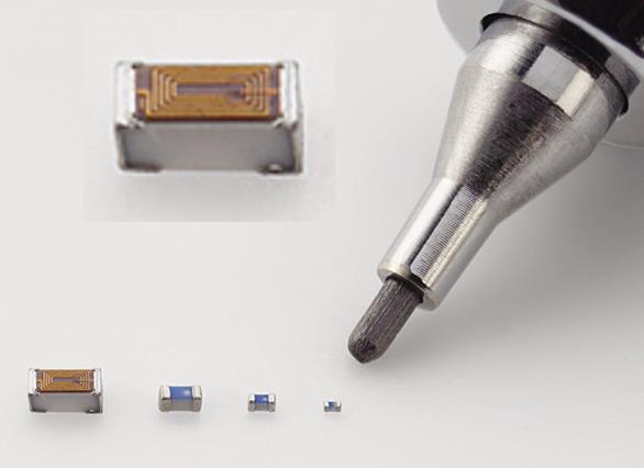
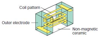


16 Chip Inductor Construction www. delevan. com www. murata. com 0402 = mill = mm 16


17 Inductors The self inductance of an inductor relates to the total number of magnetic flux lines produced and encircled by the inductor: L = Φ Total i Here L is the inductance and I is the current, and Φ Total is total flux encircle. The number of flux lines Φ depends on the normal component of the magnetic flux density B, and the area A and is: The magnetic flux density in an N-turn air-core solenoid with length l and current i is Φ = BA B = μ 0Ni l Consequently: Φ = BA = μ 0Ni l A Φ Total = NΦ = N μ 0Ni l A = μ 0N 2 i l A So that L = Φ Total i = μ 0N 2 A l l In general, the inductance is proportional to the area enclosed, and inversely proportional to the length. For magnetic materials μ 0 μ r μ 0 Area i i 17
18 Inductors It turns out (no pun intended) that is quite difficult find analytical solutions for the inductance of coils, except for a few cases such as the long solenoid. For example, from Wikipedia, here is the formula for a single-layer solenoid in air and then there is the skin and proximity effect, capacitance between the windings, etc. Because of this, various approximations and empirical formulas have been developed. 18


 Short (l) air-core inductor.")
19 Some Air-Core Inductance Formulas Ideal, very long, air-core solenoid. Often derived in EM theory textbooks. l 2R L = μ 0N 2 R 2 l R in mm, l in cm, L in μh Shorter air-core solenoid. The approximations that are used in the derivation of ideal solenoids don t apply. Called long and short by various people. l 0.8 L = 10πr2 μ 0 N 2 9R + 10l R, l in cm, L in μh Very popular formula. You will encounter similarly-looking equations with different constants. The different constant take care of the different units of measure (mm, inch, etc.) Short (l) air-core inductor. K is the socalled Nagoaka factor. That can be found in various references. l < 0.8R L = πμ 0N 2 R 2 l K R, l in cm, L in μh 19


20 Reality-Check Inductance Formulas While calculating the inductance accurately is a worthwhile endeavor, in many practical situations it is less important. For example, assuming one has very accurate formula for the inductance of a solenoid. Then using this formula one calculates the number of turns to realize a particular inductance. Very rarely will the number of turns be an integer. One could make an inductor with, say 22½ turns, but how would one make a inductor with turns? It is common in RF work to wind a solenoid as accurately as possible, but assume one will not get to the exact value. Small deviation from the desired value can be accounted for in various ways. For example, air-core coils can be changed by slightly pressing the coil to adjust the pitch. It is important though, to have a solid understanding of how the inductor length, area, and number of turn affect the value of the inductance. Also, one should have a good understanding of skin effect, proximity effect, inductor resistance, frequency etc. affect the inductance. 20
 X = jωl Frequency/phasor domain (steady state sinusoidal). Reactance (Ω) V = ωli m θ i + 90 Frequency/phasor domain (steady state sinusoidal).")
21 Inductor Assuming the inductance L is known, we use the following equations for circuit analysis. v(t) = L di dt Time domain. Differential equation E = 1 2 Li2 Energy (Joule) X = jωl Frequency/phasor domain (steady state sinusoidal). Reactance (Ω) V = ωli m θ i + 90 Frequency/phasor domain (steady state sinusoidal). V leads by 90 X = sl τ = R L s-domain s = σ + jω Time constant for a single time constant circuit, L reactive element 21
22 Inductors Practical inductors have distributed resistance and inductance. Also, the conductors are subject to skin effect and the proximity effect. An equivalent circuit for an inductor at high frequencies. Note that at some frequency this inductor will resonate with its own capacitance. That frequency is called the self resonance frequency (SFR) At frequencies higher than the SRF, the inductor appears as a capacitor in the circuit. 22
, except in specialized audio")


23 Applications of Inductors in RF It is not very common to see inductor used in analog signal processing (filters), except in specialized audio applications. In RF, inductors are widely used in filters. We will see what later. At low frequencies, inductor are used in transformer to step up/down voltages levels. Not quite as common, they are also used for impedance-matching. In RF inductors, along with capacitors are extensively used to transform impedances in order to optimize power transfer. 1K jx c 1K jx C 100 Ω +jx C 100 Ω jx C 100 Ω We want 1K to appear as 100 Ω Add a shunt capacitor that has a reactance jx C Calculating the input impedance shows we have the correct R, but there is a reactance jx C in series No problem, add an inductor to cancel out the capacitor's reactance At the operating frequency the 1K resistor appears as a 100 Ω resistor 23
24 24
Radio Frequency Electronics
 Radio Frequency Electronics Preliminaries III Lee de Forest Born in Council Bluffs, Iowa in 1873 Had 180 patents Invented the vacuum tube that allows for building electronic amplifiers Vacuum tube started
Radio Frequency Electronics
 Radio Frequency Electronics Preliminaries IV Born 22 February 1857, died 1 January 1894 Physicist Proved conclusively EM waves (theorized by Maxwell ), exist. Hz names in his honor. Created the field of
Radio Frequency Electronics
 Radio Frequency Electronics Frederick Emmons Terman Transformers Masters degree from Stanford and Ph.D. from MIT Later a professor at Stanford His students include William Hewlett and David Packard Wrote
Chapter 2. Inductor Design for RFIC Applications
 Chapter 2 Inductor Design for RFIC Applications 2.1 Introduction A current carrying conductor generates magnetic field and a changing current generates changing magnetic field. According to Faraday s laws
R. W. Erickson. Department of Electrical, Computer, and Energy Engineering University of Colorado, Boulder
 R. W. Erickson Department of Electrical, Computer, and Energy Engineering University of Colorado, Boulder 13.2.3 Leakage inductances + v 1 (t) i 1 (t) Φ l1 Φ M Φ l2 i 2 (t) + v 2 (t) Φ l1 Φ l2 i 1 (t)
EE 340 Transmission Lines. Spring 2012
 EE 340 Transmission Lines Spring 2012 Physical Characteristics Overhead lines An overhead transmission line usually consists of three conductors or bundles of conductors containing the three phases of
Department of Electrical and Computer Engineering Lab 6: Transformers
 ESE Electronics Laboratory A Department of Electrical and Computer Engineering 0 Lab 6: Transformers. Objectives ) Measure the frequency response of the transformer. ) Determine the input impedance of
EE 340 Transmission Lines
 EE 340 Transmission Lines Physical Characteristics Overhead lines An overhead transmission line usually consists of three conductors or bundles of conductors containing the three phases of the power system.
Chapter 2. The Fundamentals of Electronics: A Review
 Chapter 2 The Fundamentals of Electronics: A Review Topics Covered 2-1: Gain, Attenuation, and Decibels 2-2: Tuned Circuits 2-3: Filters 2-4: Fourier Theory 2-1: Gain, Attenuation, and Decibels Most circuits
Properties of Inductor and Applications
 LABORATORY Experiment 3 Properties of Inductor and Applications 1. Objectives To investigate the properties of inductor for different types of magnetic material To calculate the resonant frequency of a
PHYS 1444 Section 501 Lecture #20
 PHYS 1444 Section 501 Lecture #0 Monday, Apr. 17, 006 Transformer Generalized Faraday s Law Inductance Mutual Inductance Self Inductance Inductor Energy Stored in the Magnetic Field 1 Announcements Quiz
Inductors & Resonance
 Inductors & Resonance The Inductor This figure shows a conductor carrying a current. A magnetic field is set up around the conductor as concentric circles. If a coil of wire has a current flowing through
PHYS 1441 Section 001 Lecture #22 Wednesday, Nov. 29, 2017
 PHYS 1441 Section 001 Lecture #22 Chapter 29:EM Induction & Faraday s Law Transformer Electric Field Due to Changing Magnetic Flux Chapter 30: Inductance Mutual and Self Inductance Energy Stored in Magnetic
Aligarh College of Engineering & Technology (College Code: 109) Affiliated to UPTU, Approved by AICTE Electrical Engg.
 Affiliated to UPTU, Approved by AICTE Electrical Engg.") Aligarh College of Engineering & Technology (College Code: 19) Electrical Engg. (EE-11/21) Unit-I DC Network Theory 1. Distinguish the following terms: (a) Active and passive elements (b) Linearity and
Aligarh College of Engineering & Technology (College Code: 19) Electrical Engg. (EE-11/21) Unit-I DC Network Theory 1. Distinguish the following terms: (a) Active and passive elements (b) Linearity and
Experiment 4: Grounding and Shielding
 4-1 Experiment 4: Grounding and Shielding Power System Hot (ed) Neutral (White) Hot (Black) 115V 115V 230V Ground (Green) Service Entrance Load Enclosure Figure 1 Typical residential or commercial AC power
Iron Powder Core Selection For RF Power Applications. Jim Cox Micrometals, Inc. Anaheim, CA
 HOME APPLICATION NOTES Iron Powder Core Selection For RF Power Applications Jim Cox Micrometals, Inc. Anaheim, CA Purpose: The purpose of this article is to present new information that will allow the
Iron Powder Cores for High Q Inductors By: Jim Cox - Micrometals, Inc.
 HOME APPLICATION NOTES Iron Powder Cores for High Q Inductors By: Jim Cox - Micrometals, Inc. SUBJECT: A brief overview will be given of the development of carbonyl iron powders. We will show how the magnetic
Study of Inductive and Capacitive Reactance and RLC Resonance
 Objective Study of Inductive and Capacitive Reactance and RLC Resonance To understand how the reactance of inductors and capacitors change with frequency, and how the two can cancel each other to leave
Electronic Instrumentation
 10/1/014 1 Electronic Instrumentation Experiment 3 Part A: Making an Inductor Part B: Measurement of Inductance Part C: imulation of a Transformer Part D: Making a Transformer Inductors & Transformers
3. What is hysteresis loss? Also mention a method to minimize the loss. (N-11, N-12)
") DHANALAKSHMI COLLEGE OF ENGINEERING, CHENNAI DEPARTMENT OF ELECTRICAL AND ELECTRONICS ENGINEERING EE 6401 ELECTRICAL MACHINES I UNIT I : MAGNETIC CIRCUITS AND MAGNETIC MATERIALS Part A (2 Marks) 1. List
DHANALAKSHMI COLLEGE OF ENGINEERING, CHENNAI DEPARTMENT OF ELECTRICAL AND ELECTRONICS ENGINEERING EE 6401 ELECTRICAL MACHINES I UNIT I : MAGNETIC CIRCUITS AND MAGNETIC MATERIALS Part A (2 Marks) 1. List
Resonant Mode of Inductors with Reactive Power Self-compensation
 International Scientific Colloquium Modelling for Material Processing Riga, June 8-9, 26 Resonant Mode of Inductors with Reactive Power Self-compensation B.B. Utegulov, I.V. Zakharov, A.D. Izhikova Abstract
CHAPTER 6: ALTERNATING CURRENT
 CHAPTER 6: ALTERNATING CURRENT PSPM II 2005/2006 NO. 12(C) 12. (c) An ac generator with rms voltage 240 V is connected to a RC circuit. The rms current in the circuit is 1.5 A and leads the voltage by
PHYSICS WORKSHEET CLASS : XII. Topic: Alternating current
 PHYSICS WORKSHEET CLASS : XII Topic: Alternating current 1. What is mean by root mean square value of alternating current? 2. Distinguish between the terms effective value and peak value of an alternating
SELF-RESONANCE IN COILS and the self-capacitance myth
 SELF-RESONANCE IN COILS and the self-capacitance myth All coils show a self-resonant frequency (SRF), and as this frequency is approached the inductance and resistance increase while the Q decreases until
PHYS 1442 Section 004 Lecture #15
 PHYS 1442 Section 004 Lecture #15 Monday March 17, 2014 Dr. Andrew Brandt Chapter 21 Generator Transformer Inductance 3/17/2014 1 PHYS 1442-004, Dr. Andrew Brandt Announcements HW8 on Ch 21-22 will be
application note Philips Magnetic Products Cable Shielding Philips Components
 application note Cable Shielding Philips Components Cable Shielding Contents Introduction 3 EMI suppression and cable shielding with ferrites 4 Ferrite selection 6 Material properties 7 Ferrite core and
VLSI is scaling faster than number of interface pins
 High Speed Digital Signals Why Study High Speed Digital Signals Speeds of processors and signaling Doubled with last few years Already at 1-3 GHz microprocessors Early stages of terahertz Higher speeds
Experiment 5: Grounding and Shielding
 Experiment 5: Grounding and Shielding Power System Hot (Red) Neutral (White) Hot (Black) 115V 115V 230V Ground (Green) Service Entrance Load Enclosure Figure 1 Typical residential or commercial AC power
Spring 2000 EE361: MIDTERM EXAM 1
 NAME: STUDENT NUMBER: Spring 2000 EE361: MIDTERM EXAM 1 This exam is open book and closed notes. Assume f=60 hz and use the constant µ o =4π 10-7 wherever necessary. Be sure to show all work clearly. 1.
Homework Assignment 05
 Homework Assignment 05 Question (2 points each unless otherwise indicated)(20 points). Estimate the parallel parasitic capacitance of a mh inductor with an SRF of 220 khz. Answer: (2π)(220 0 3 ) = ( 0
PRELIMINARIES. Generators and loads are connected together through transmission lines transporting electric power from one place to another.
 TRANSMISSION LINES PRELIMINARIES Generators and loads are connected together through transmission lines transporting electric power from one place to another. Transmission line must, therefore, take power
Units. In the following formulae all lengths are expressed in centimeters. The inductance calculated will be in micro-henries = 10-6 henry.
 INDUCTANCE Units. In the following formulae all lengths are expressed in centimeters. The inductance calculated will be in micro-henries = 10-6 henry. Long straight round wire. If l is the length; d, the
CH 1. Large coil. Small coil. red. Function generator GND CH 2. black GND
 Experiment 6 Electromagnetic Induction "Concepts without factual content are empty; sense data without concepts are blind... The understanding cannot see. The senses cannot think. By their union only can
Review 6. unlike poles cause the magnets to attract. like poles cause the magnets to repel.
 Review 6 1. The two characteristics of all magnets are: they attract and hold Iron, and, if free to move, they will assume roughly a south - north position. 2. Lines of flux always leave the north pole
What is an Inductor? Token Electronics Industry Co., Ltd. Version: January 16, Web:
 Version: January 16, 2017 What is an Inductor? Web: www.token.com.tw Email: rfq@token.com.tw Token Electronics Industry Co., Ltd. Taiwan: No.137, Sec. 1, Zhongxing Rd., Wugu District, New Taipei City,
Accurate Models for Spiral Resonators
 MITSUBISHI ELECTRIC RESEARCH LABORATORIES http://www.merl.com Accurate Models for Spiral Resonators Ellstein, D.; Wang, B.; Teo, K.H. TR1-89 October 1 Abstract Analytically-based circuit models for two
TUNED AMPLIFIERS 5.1 Introduction: Coil Losses:
 TUNED AMPLIFIERS 5.1 Introduction: To amplify the selective range of frequencies, the resistive load R C is replaced by a tuned circuit. The tuned circuit is capable of amplifying a signal over a narrow
Investigation of a Voltage Probe in Microstrip Technology
 Investigation of a Voltage Probe in Microstrip Technology (Specifically in 7-tesla MRI System) By : Mona ParsaMoghadam Supervisor : Prof. Dr. Ing- Klaus Solbach April 2015 Introduction - Thesis work scope
Electromagnetic Induction
 Chapter 16 Electromagnetic Induction In This Chapter: Electromagnetic Induction Faraday s Law Lenz s Law The Transformer Self-Inductance Inductors in Combination Energy of a Current-Carrying Inductor Electromagnetic
ELECTROMAGNETIC INDUCTION AND ALTERNATING CURRENT (Assignment)
") ELECTROMAGNETIC INDUCTION AND ALTERNATING CURRENT (Assignment) 1. In an A.C. circuit A ; the current leads the voltage by 30 0 and in circuit B, the current lags behind the voltage by 30 0. What is the
ELECTROMAGNETIC INDUCTION AND ALTERNATING CURRENT (Assignment) 1. In an A.C. circuit A ; the current leads the voltage by 30 0 and in circuit B, the current lags behind the voltage by 30 0. What is the
Chapter Moving Charges and Magnetism
 100 Chapter Moving Charges and Magnetism 1. The power factor of an AC circuit having resistance (R) and inductance (L) connected in series and an angular velocity ω is [2013] 2. [2002] zero RvB vbl/r vbl
13 th Asian Physics Olympiad India Experimental Competition Wednesday, 2 nd May 2012
 13 th Asian Physics Olympiad India Experimental Competition Wednesday, nd May 01 Please first read the following instructions carefully: 1. The time available is ½ hours for each of the two experimental
ELECTROMAGNETIC COMPATIBILITY HANDBOOK 1. Chapter 8: Cable Modeling
 ELECTROMAGNETIC COMPATIBILITY HANDBOOK 1 Chapter 8: Cable Modeling Related to the topic in section 8.14, sometimes when an RF transmitter is connected to an unbalanced antenna fed against earth ground
Inductor and Transformer Design
 Inductor and Transformer Design 1 Introduction The conditioning of power flow in Power Electronic Systems (PES) is done through the use of electromagnetic elements (inductors and transformers). In this
Inductance of solenoids with Cobra3
 Inductance of solenoids with Cobra3 TEP Related topics Law of inductance, Lenz s law, self-inductance, solenoids, transformer, oscillatory circuit, resonance, damped oscillation, logarithmic decrement,
Non-Ideal Behavior of Components
 Non-Ideal Behavior of Components Todd H. Hubing Dept. of Electrical and Computer Engineering Clemson, University Clemson, SC 29634 USA email: hubing@clemson.edu Telephone: 1-864-656-7219 Circuit Schematics
Class XII Chapter 7 Alternating Current Physics
 Question 7.1: A 100 Ω resistor is connected to a 220 V, 50 Hz ac supply. (a) What is the rms value of current in the circuit? (b) What is the net power consumed over a full cycle? Resistance of the resistor,
Sirindhorn International Institute of Technology Thammasat University
 Sirindhorn International Institute of Technology Thammasat University School of Information, Computer and Communication Technology COURSE : ECS 34 Basic Electrical Engineering Lab INSTRUCTOR : Dr. Prapun
Chapter 2-1 Transformers
 Principles of Electric Machines and Power Electronics Chapter 2-1 Transformers Third Edition P. C. Sen Transformer application 1: power transmission Ideal Transformer Assumptions: 1. Negligible winding
University of Pennsylvania Moore School of Electrical Engineering ESE319 Electronic Circuits - Modeling and Measurement Techniques
 University of Pennsylvania Moore School of Electrical Engineering ESE319 Electronic Circuits - Modeling and Measurement Techniques 1. Introduction. Students are often frustrated in their attempts to execute
R. W. Erickson. Department of Electrical, Computer, and Energy Engineering University of Colorado, Boulder
 R. W. Erickson Department of Electrical, Computer, and Energy Engineering University of Colorado, Boulder 13.3.2 Low-frequency copper loss DC resistance of wire R = ρ l b A w where A w is the wire bare
Transformers. Department of Physics & Astronomy Texas Christian University, Fort Worth, TX. April 23, 2013
 Transformers Department of Physics & Astronomy Texas Christian University, Fort Worth, TX April 23, 2013 1 Introduction In the early nineteenth century, Hans Christian Øersted discovered that a magnetic
WELCOME TO THE LECTURE
 WLCOM TO TH LCTUR ON TRNFORMR Single Phase Transformer Three Phase Transformer Transformer transformer is a stationary electric machine which transfers electrical energy (power) from one voltage level
Electronic Instrumentation
 10/15/01 1 Electronic Instrumentation Experiment 3 Part A: Making an Inductor Part B: Measurement of Inductance Part C: imulation of a Transformer Part D: Making a Transformer Review RC and Resonance How
GLOSSARY OF TERMS FLUX DENSITY:
 ADSL: Asymmetrical Digital Subscriber Line. Technology used to transmit/receive data and audio using the pair copper telephone lines with speed up to 8 Mbps. AMBIENT TEMPERATURE: The temperature surrounding
Electrical Theory 2 Lessons for Fall Semester:
 Electrical Theory 2 Lessons for Fall Semester: Lesson 1 Magnetism Lesson 2 Introduction to AC Theory Lesson 3 Lesson 4 Capacitance and Capacitive Reactance Lesson 5 Impedance and AC Circuits Lesson 6 AC
Lecture 4 RF Amplifier Design. Johan Wernehag, EIT. Johan Wernehag Electrical and Information Technology
 Lecture 4 RF Amplifier Design Johan Wernehag, EIT Johan Wernehag Electrical and Information Technology Lecture 4 Design of Matching Networks Various Purposes of Matching Voltage-, Current- and Power Matching
Topic 4 Practical Magnetic Design: Inductors and Coupled Inductors
 Topic 4 Practical Magnetic Design: Inductors and Coupled Inductors Louis Diana Agenda Theory of operation and design equations Design flow diagram discussion Inductance calculations Ampere s law for magnetizing
Renco Electronics, Inc.
 Abstract The operating frequency of most electronic circuits has been increasing since the late 1950 s. While the increase in frequency has reduced the overall weight and size of most consumer electronics
Equivalent Circuit Model Overview of Chip Spiral Inductors
 Equivalent Circuit Model Overview of Chip Spiral Inductors The applications of the chip Spiral Inductors have been widely used in telecommunication products as wireless LAN cards, Mobile Phone and so on.
Oscillators. An oscillator may be described as a source of alternating voltage. It is different than amplifier.
 Oscillators An oscillator may be described as a source of alternating voltage. It is different than amplifier. An amplifier delivers an output signal whose waveform corresponds to the input signal but
EE 740 Transmission Lines
 EE 740 Transmission Lines 1 High Voltage Power Lines (overhead) Common voltages in north America: 138, 230, 345, 500, 765 kv Bundled conductors are used in extra-high voltage lines Stranded instead of
Alternating current circuits- Series RLC circuits
 FISI30 Física Universitaria II Professor J.. ersosimo hapter 8 Alternating current circuits- Series circuits 8- Introduction A loop rotated in a magnetic field produces a sinusoidal voltage and current.
Analysis of High Efficiency Multistage Matching Networks with Volume Constraint
 Analysis of High Efficiency Multistage Matching Networks with Volume Constraint Phyo Aung Kyaw, Aaron.F. Stein, Charles R. Sullivan Thayer School of Engineering at Dartmouth Hanover, NH 03755, USA {phyo.a.kyaw.th,
Single-turn and multi-turn coil domains in 3D COMSOL. All rights reserved.
 Single-turn and multi-turn coil domains in 3D 2012 COMSOL. All rights reserved. Introduction This tutorial shows how to use the Single-Turn Coil Domain and Multi-Turn Coil Domain features in COMSOL s Magnetic
Electromagnetic Induction - A
 Electromagnetic Induction - A APPARATUS 1. Two 225-turn coils 2. Table Galvanometer 3. Rheostat 4. Iron and aluminum rods 5. Large circular loop mounted on board 6. AC ammeter 7. Variac 8. Search coil
Components, those bits and pieces which make up
 COMPONENTS and Systems CHAPTER 1 Components, those bits and pieces which make up a radio frequency (RF) circuit, seem at times to be taken for granted. A capacitor is, after all, a capacitor isn t it?
20 meter bandstop filter notes
 1 Introduction 20 meter bandstop filter notes Kevin E. Schmidt, W9CF 6510 S. Roosevelt St. Tempe, AZ 85283 USA A shorted half-wavelength stub cut for 20 meters acts as a bandstop filter for 10 and 20 meters,
PHYS 1444 Section 003 Lecture #19
 PHYS 1444 Section 003 Lecture #19 Monday, Nov. 14, 2005 Electric Generators DC Generator Eddy Currents Transformer Mutual Inductance Today s homework is homework #10, due noon, next Tuesday!! 1 Announcements
Alternating Current. Slide 1 / 69. Slide 2 / 69. Slide 3 / 69. Topics to be covered. Sources of Alternating EMF. Sources of alternating EMF
 Slide 1 / 69 lternating urrent Sources of alternating EMF Transformers ircuits and Impedance Topics to be covered Slide 2 / 69 LR Series ircuits Resonance in ircuit Oscillations Sources of lternating EMF
Alternating Current. Slide 2 / 69. Slide 1 / 69. Slide 3 / 69. Slide 4 / 69. Slide 6 / 69. Slide 5 / 69. Topics to be covered
 Slide 1 / 69 lternating urrent Sources of alternating EMF ircuits and Impedance Slide 2 / 69 Topics to be covered LR Series ircuits Resonance in ircuit Oscillations Slide 3 / 69 Sources of lternating EMF
Design of Integrated LC Filter Using Multilayer Flexible Ferrite Sheets S. Coulibaly 1, G. Loum 1, K.A. Diby 2
 IOSR Journal of Electrical and Electronics Engineering (IOSR-JEEE) e-issn: 2278-1676,p-ISSN: 232-3331, Volume 1, Issue 6 Ver. I (Nov Dec. 215), PP 35-43 www.iosrjournals.org Design of Integrated LC Filter
Simple AC Circuits. Introduction
 Simple AC Circuits Introduction Each problem in this problem set involves the steady state response of a linear, time-invariant circuit to a single sinusoidal input. Such a response is known to be sinusoidal
Bucking Coils produce Energy Gain Cyril Smith, 2015
 Bucking Coils produce Energy Gain Cyril Smith, 015 1. Introduction There are many claims of overunity for systems that employ bucking coils. These are coils mounted on a common core and connected in series
Introduction. Inductors in AC Circuits.
 Module 3 AC Theory What you ll learn in Module 3. Section 3.1 Electromagnetic Induction. Magnetic Fields around Conductors. The Solenoid. Section 3.2 Inductance & Back e.m.f. The Unit of Inductance. Factors
1. If the flux associated with a coil varies at the rate of 1 weber/min,the induced emf is
 1. f the flux associated with a coil varies at the rate of 1 weber/min,the induced emf is 1 1. 1V 2. V 60 3. 60V 4. Zero 2. Lenz s law is the consequence of the law of conservation of 1. Charge 2. Mass
Lecture 4. Maximum Transfer of Power. The Purpose of Matching. Lecture 4 RF Amplifier Design. Johan Wernehag Electrical and Information Technology
 Johan Wernehag, EIT Lecture 4 RF Amplifier Design Johan Wernehag Electrical and Information Technology Design of Matching Networks Various Purposes of Matching Voltage-, Current- and Power Matching Design
Understanding and Optimizing Electromagnetic Compatibility in Switchmode Power Supplies
 Understanding and Optimizing Electromagnetic Compatibility in Switchmode Power Supplies 1 Definitions EMI = Electro Magnetic Interference EMC = Electro Magnetic Compatibility (No EMI) Three Components
MAHALAKSHMI ENGINEERING COLLEGE TIRUCHIRAPALLI UNIT III TUNED AMPLIFIERS PART A (2 Marks)
") MAHALAKSHMI ENGINEERING COLLEGE TIRUCHIRAPALLI-621213. UNIT III TUNED AMPLIFIERS PART A (2 Marks) 1. What is meant by tuned amplifiers? Tuned amplifiers are amplifiers that are designed to reject a certain
MAHALAKSHMI ENGINEERING COLLEGE TIRUCHIRAPALLI-621213. UNIT III TUNED AMPLIFIERS PART A (2 Marks) 1. What is meant by tuned amplifiers? Tuned amplifiers are amplifiers that are designed to reject a certain
University of Pittsburgh
 University of Pittsburgh Experiment #11 Lab Report Inductance/Transformers Submission Date: 12/04/2017 Instructors: Dr. Minhee Yun John Erickson Yanhao Du Submitted By: Nick Haver & Alex Williams Station
Non-ideal Behavior of Electronic Components at High Frequencies and Associated Measurement Problems
 Nonideal Behavior of Electronic Components at High Frequencies and Associated Measurement Problems Matthew Beckler beck0778@umn.edu EE30 Lab Section 008 October 27, 2006 Abstract In the world of electronics,
AP Physics C. Alternating Current. Chapter Problems. Sources of Alternating EMF
 AP Physics C Alternating Current Chapter Problems Sources of Alternating EMF 1. A 10 cm diameter loop of wire is oriented perpendicular to a 2.5 T magnetic field. What is the magnetic flux through the
The SI unit of inductance is the henry, defined as:
 Inductors A coil of wire, or solenoid, can be used in a circuit to store energy in the magnetic field. We define the inductance of a solenoid having N turns, length l and cross-section area A as: The SI
A Simple Wideband Transmission Line Model
 A Simple Wideband Transmission Line Model Prepared by F. M. Tesche Holcombe Dept. of Electrical and Computer Engineering College of Engineering & Science 337 Fluor Daniel Building Box 34915 Clemson, SC
Core Technology Group Application Note 1 AN-1
 Measuring the Impedance of Inductors and Transformers. John F. Iannuzzi Introduction In many cases it is necessary to characterize the impedance of inductors and transformers. For instance, power supply
K6RIA, Extra Licensing Class. Circuits & Resonance for All!
 K6RIA, Extra Licensing Class Circuits & Resonance for All! Amateur Radio Extra Class Element 4 Course Presentation ELEMENT 4 Groupings Rules & Regs Skywaves & Contesting Outer Space Comms Visuals & Video
Lab E2: B-field of a Solenoid. In the case that the B-field is uniform and perpendicular to the area, (1) reduces to
 reduces to") E2.1 Lab E2: B-field of a Solenoid In this lab, we will explore the magnetic field created by a solenoid. First, we must review some basic electromagnetic theory. The magnetic flux over some area A is
E2.1 Lab E2: B-field of a Solenoid In this lab, we will explore the magnetic field created by a solenoid. First, we must review some basic electromagnetic theory. The magnetic flux over some area A is
Chapter 33. Alternating Current Circuits
 Chapter 33 Alternating Current Circuits Alternating Current Circuits Electrical appliances in the house use alternating current (AC) circuits. If an AC source applies an alternating voltage to a series
Designing VHF Lumped-Element Couplers With MW Office
 Designing VHF umped-element Couplers With MW Office Steve Maas, Chief Technology Officer Applied Wave Research, Inc. Copyright (C) 999 Applied Wave Research, Inc.; All Rights Reserved. Abstract This note
VE7CNF - 630m Antenna Matching Measurements Using an Oscilloscope
 VE7CNF - 630m Antenna Matching Measurements Using an Oscilloscope Toby Haynes October, 2016 1 Contents VE7CNF - 630m Antenna Matching Measurements Using an Oscilloscope... 1 Introduction... 1 References...
West Coast Magnetics. Advancing Power Electronics FOIL WINDINGS FOR SMPS INDUCTORS AND TRANSFORMERS. Weyman Lundquist, CEO and Engineering Manager
 1 West Coast Magnetics Advancing Power Electronics FOIL WINDINGS FOR SMPS INDUCTORS AND TRANSFORMERS Weyman Lundquist, CEO and Engineering Manager TYPES OF WINDINGS 2 Solid wire Lowest cost Low DC resistance
Outcomes: Core Competencies for ECE145A/218A
 Outcomes: Core Competencies for ECE145A/18A 1. Transmission Lines and Lumped Components 1. Use S parameters and the Smith Chart for design of lumped element and distributed L matching networks. Able to
Reg. No. : BASIC ELECTRICAL TECHNOLOGY (ELE 101)
") Department of Electrical and Electronics Engineering Reg. No. : MNIPL INSTITUTE OF TECHNOLOGY, MNIPL ( Constituent Institute of Manipal University, Manipal) FIRST SEMESTER B.E. DEGREE MKEUP EXMINTION (REVISED
Department of Electrical and Electronics Engineering Reg. No. : MNIPL INSTITUTE OF TECHNOLOGY, MNIPL ( Constituent Institute of Manipal University, Manipal) FIRST SEMESTER B.E. DEGREE MKEUP EXMINTION (REVISED
Passive Component Analysis. OMICRON Lab Webinar Nov. 2015
 Passive Component Analysis OMICRON Lab Webinar Nov. 2015 Webinar Hints Activate the chat function Please mute your microphones to avoid echoes Feel free to post questions anytime using the chat function
The design of Ruthroff broadband voltage transformers M. Ehrenfried G8JNJ
 The design of Ruthroff broadband voltage transformers M. Ehrenfried G8JNJ Introduction I started investigating balun construction as a result of various observations I made whilst building HF antennas.
EE301 ELECTRONIC CIRCUITS CHAPTER 2 : OSCILLATORS. Lecturer : Engr. Muhammad Muizz Bin Mohd Nawawi
 EE301 ELECTRONIC CIRCUITS CHAPTER 2 : OSCILLATORS Lecturer : Engr. Muhammad Muizz Bin Mohd Nawawi 2.1 INTRODUCTION An electronic circuit which is designed to generate a periodic waveform continuously at
INF 5490 RF MEMS. LN12: RF MEMS inductors. Spring 2011, Oddvar Søråsen Department of informatics, UoO
 INF 5490 RF MEMS LN12: RF MEMS inductors Spring 2011, Oddvar Søråsen Department of informatics, UoO 1 Today s lecture What is an inductor? MEMS -implemented inductors Modeling Different types of RF MEMS
An induced emf is the negative of a changing magnetic field. Similarly, a self-induced emf would be found by
 This is a study guide for Exam 4. You are expected to understand and be able to answer mathematical questions on the following topics. Chapter 32 Self-Induction and Induction While a battery creates an
UNIVERSITY OF TECHNOLOGY By: Fadhil A. Hasan ELECTRICAL MACHINES
 UNIVERSITY OF TECHNOLOGY DEPARTMENT OF ELECTRICAL ENGINEERING Year: Second 2016-2017 By: Fadhil A. Hasan ELECTRICAL MACHINES І Module-II: AC Transformers o Single phase transformers o Three-phase transformers
EE 741. Primary & Secondary Distribution Systems
 EE 741 Primary & Secondary Distribution Systems Radial-Type Primary Feeder Most common, simplest and lowest cost Example of Overhead Primary Feeder Layout Example of Underground Primary Feeder Layout Radial-Type