EE 340 Transmission Lines
|
|
|
- Erin Jackson
- 6 years ago
- Views:
Transcription

1 EE 340 Transmission Lines


2 Physical Characteristics Overhead lines An overhead transmission line usually consists of three conductors or bundles of conductors containing the three phases of the power system. In overhead transmission lines, the bare conductors are suspended from a pole or a tower via insulators. The conductors are usually made of aluminum cable steel reinforced (ACSR).


3 Physical Characteristics underground cables Cable lines are designed to be placed underground or under water. The conductors are insulated from one another and surrounded by protective sheath. Cable lines are more expensive and harder to maintain. They also have capacitance problem not suitable for long distance.
4 Electrical Characteristics Transmission lines are characterized by a series resistance, inductance, and shunt capacitance per unit length. These values determine the power-carrying capacity of the transmission line and the voltage drop across it at full load. The DC resistance of a conductor is expressed in terms of resistively, length and cross sectional area as follows:
5 Cable resistance The resistively increases linearly with temperature over normal range of temperatures. If the resistively at one temperature and material temperature constant are known, the resistively at another temperature can be found by


6 Cable Resistance AC resistance of a conductor is always higher than its DC resistance due to the skin effect forcing more current flow near the outer surface of the conductor. The higher the frequency of current, the more noticeable skin effect would be. Wire manufacturers usually supply tables of resistance per unit length at common frequencies (50 and 60 Hz). Therefore, the resistance can be determined from such tables.
7 Line inductance
8 Remarks on line inductance The greater the spacing between the phases of a transmission line, the greater the inductance of the line. Since the phases of a high-voltage overhead transmission line must be spaced further apart to ensure proper insulation, a high-voltage line will have a higher inductance than a low-voltage line. Since the spacing between lines in buried cables is very small, series inductance of cables is much smaller than the inductance of overhead lines The greater the radius of the conductors in a transmission line, the lower the inductance of the line. In practical transmission lines, instead of using heavy and inflexible conductors of large radii, two and more conductors are bundled together to approximate a large diameter conductor, and reduce corona loss.
9 Per-Phase Inductance of 3-phase transmission line
: (ε = 8.")
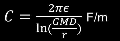
10 Shunt capacitance Since a voltage V is applied to a pair of conductors separated by a dielectric (air), charges q of equal magnitude but opposite sign will accumulate on the conductors. Capacitance C between the two conductors is defined by q C V The capacitance of a single-phase transmission line is given by (see derivation in the book): (ε = 8.85 x F/m)
11 Capacitance of 3-phase transmission line
12 Remarks on line capacitance 1. The greater the spacing between the phases of a transmission line, the lower the capacitance of the line. Since the phases of a high-voltage overhead transmission line must be spaced further apart to ensure proper insulation, a high-voltage line will have a lower capacitance than a low-voltage line. Since the spacing between lines in buried cables is very small, shunt capacitance of cables is much larger than the capacitance of overhead lines. 2. The greater the radius of the conductors in a transmission line, the higher the capacitance of the line. Therefore, bundling increases the capacitance.
13 Short line model Overhead transmission lines shorter than 50 miles can be modeled as a series resistance and inductance, since the shunt capacitance can be neglected over short distances. The total series resistance and series reactance can be calculated as where r, x are resistance and reactance per unit length and d is the length of the transmission line.
14 Two-port network model: Short line model The equation is similar to that of a synchronous generator and transformer (w/o shunt impedance)
15 Short line Voltage Regulation: 1. If unity-pf (resistive) loads are added at the end of a line, the voltage at the end of the transmission line decreases slightly small positive VR. 2. If leading (capacitive) loads are added at the end of a line, the voltage at the end of the transmission line increases negative VR. 3. If lagging (inductive) loads are added at the end of a line, the voltage at the end of the transmission line decreases significantly large positive VR.
16 Input powers Power flow and efficiency Output powers Efficiency
17 Short line simplified If the resistance of the line is ignored, then Therefore, for fixed voltages, the power flow through a transmission line depends on the angle between the input and output voltages. Maximum power flow occurs when δ = 90 o. Notes: The maximum power handling capability of a transmission line is a function of the square of its voltage. The maximum power handling capability of a transmission line is inversely proportional to its series reactance (some very long lines include series capacitors to reduce the total series reactance). The angle δ controls the power flow through the line. Hence, it is possible to control power flow by placing a phase-shifting transformer.
18 Example A line with reactance X and negligible resistance supplies a pure resistive load from a fixed source V S. Determine the maximum power transfer, and the load voltage V R at which this occurs. (Hint: recall the maximum power transfer theorem from your basic circuits course) Ans: P max 2 VS 2X, V R V S 2
19 Line Characteristics To prevents excessive voltage variations in a power system, the ratio of the magnitude of the receiving end voltage to the magnitude of the ending end voltage is generally within 0.95 V S /V R 1.05 The angle δ in a transmission line should typically be 30 o to ensure that the power flow in the transmission line is well below the static stability limit. Any of these limits can be more or less important in different circumstances. In short lines, where series reactance X is relatively small, the resistive heating usually limits the power that the line can supply. In longer lines operating at lagging power factors, the voltage drop across the line is usually the limiting factor. In longer lines operating at leading power factors, the maximum angle δ can be the limiting f actor.
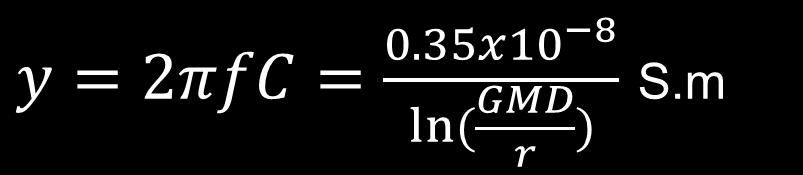
20 Medium Line ( mi) the shunt admittance must be included in calculations. However, the total admittance is usually modeled (π model) as two capacitors of equal values (each corresponding to a half of total admittance) placed at the sending and receiving ends. The total series resistance and series reactance are calculated as before. Similarly, the total shunt admittance is given by where y is the shunt admittance per unit length and d is the length of the transmission line.
21 Two-port network: Medium Line
22 Determining the Line Circuit Parameters Note: Typically, R +jx L << 1/Y Under Open-Circuit Test (phase quantities): Under Short-Circuit Test: V I S S P AV CV R R YV S 2 0, Q YVS V S P BI RI 2 R R, ZIR, Q X L I I S 2 R DI ( Y R / 2) V 2 S,
23 Long Lines ( > 150 mi) For long lines, both the shunt capacitance and the series impedance must be treated as distributed quantities. The voltages and currents on the line are found by solving the differential equations of the line. However, it is possible to model a long transmission line by a π- model but with modified series impedance Z and shunt admittance Y. Hence one can perform calculations on that model using ABCD constants. These modified values are where the propagation constant is defined by


24 Long line series and shunt compensation Shunt reactors are used to compensate the line shunt capacitance under light load or no load to regulate voltage. Series capacitors are often used to compensate the line inductive reactance in order to transfer more power.
25 Practice Problems
EE 340 Transmission Lines. Spring 2012
 EE 340 Transmission Lines Spring 2012 Physical Characteristics Overhead lines An overhead transmission line usually consists of three conductors or bundles of conductors containing the three phases of
EE 741. Primary & Secondary Distribution Systems
 EE 741 Primary & Secondary Distribution Systems Radial-Type Primary Feeder Most common, simplest and lowest cost Example of Overhead Primary Feeder Layout Example of Underground Primary Feeder Layout Radial-Type
EE 740 Transmission Lines
 EE 740 Transmission Lines 1 High Voltage Power Lines (overhead) Common voltages in north America: 138, 230, 345, 500, 765 kv Bundled conductors are used in extra-high voltage lines Stranded instead of
Transmission Line Models Part 1
 Transmission Line Models Part 1 Unlike the electric machines studied so far, transmission lines are characterized by their distributed parameters: distributed resistance, inductance, and capacitance. The
PRELIMINARIES. Generators and loads are connected together through transmission lines transporting electric power from one place to another.
 TRANSMISSION LINES PRELIMINARIES Generators and loads are connected together through transmission lines transporting electric power from one place to another. Transmission line must, therefore, take power
Fatima Michael college of Engineering and Technology
 Fatima Michael college of Engineering and Technology DEPARTMENT OF ELECTRICAL AND ELECTRONICS ENGINEERING EE2303 TRANSMISSION AND DISTRIBUTION SEM: V Question bank UNIT I INTRODUCTION 1. What is the electric
Transmission of Electrical Energy
 Transmission of Electrical Energy Electrical energy is carries by conductors such as overhead transmission lines and underground cables. The conductors are usually aluminum cable steel reinforced (ACSR),
Exercises on overhead power lines (and underground cables)
") Exercises on overhead power lines (and underground cables) 1 From the laws of Electromagnetism it can be shown that l c = 1 v 2 where v is the speed of propagation of electromagnetic waves in the environment
Exercises on overhead power lines (and underground cables) 1 From the laws of Electromagnetism it can be shown that l c = 1 v 2 where v is the speed of propagation of electromagnetic waves in the environment
EL 403 MODEL TEST PAPER - 1 POWER SYSTEMS. Time: Three Hours Maximum Marks: 100
 POWER SYSTEMS Time: Three Hours Maximum Marks: 0 Answer five questions, taking ANY TWO from Group A, any two from Group B and all from Group C. All parts of a question (a, b, etc. ) should be answered
III/IV B.Tech (Regular/Supplementary) DEGREE EXAMINATION
 DEGREE EXAMINATION") Hall Ticket Number: 14EE503 October, 2018 Fifth Semester Time: Three Hours Answer Question No.1 compulsorily. Answer ONE question from each unit. III/IV B.Tech (Regular/Supplementary) DEGREE EXAMINATION
Hall Ticket Number: 14EE503 October, 2018 Fifth Semester Time: Three Hours Answer Question No.1 compulsorily. Answer ONE question from each unit. III/IV B.Tech (Regular/Supplementary) DEGREE EXAMINATION
Radio Frequency Electronics
 Radio Frequency Electronics Preliminaries II Guglielmo Giovanni Maria Marconi Thought off by many people as the inventor of radio Pioneer in long-distance radio communications Shared Nobel Prize in 1909
Case Study 1. Power System Planning and Design: Power Plant, Transmission Lines, and Substations
 Case Study 1 Power System Planning and Design: Power Plant, Transmission Lines, and Substations Lindsay Thompson, 5203120 Presented to Riadh Habash ELG 4125 11/10/2013 1.0 ABSTRACT A power plant delivers
University of Jordan School of Engineering Electrical Engineering Department. EE 219 Electrical Circuits Lab
 University of Jordan School of Engineering Electrical Engineering Department EE 219 Electrical Circuits Lab EXPERIMENT 7 RESONANCE Prepared by: Dr. Mohammed Hawa EXPERIMENT 7 RESONANCE OBJECTIVE This experiment
Transmission Lines Ac
 We have made it easy for you to find a PDF Ebooks without any digging. And by having access to our ebooks online or by storing it on your computer, you have convenient answers with transmission lines ac.
Roll No. :... Invigilator s Signature :.. CS/B.TECH(EE)/SEM-5/EE-502/ POWER SYSTEM-I. Time Allotted : 3 Hours Full Marks : 70
/SEM-5/EE-502/ POWER SYSTEM-I. Time Allotted : 3 Hours Full Marks : 70") Name : Roll No. :.... Invigilator s Signature :.. CS/B.TECH(EE)/SEM-5/EE-502/2011-12 2011 POWER SYSTEM-I Time Allotted : 3 Hours Full Marks : 70 The figures in the margin indicate full marks. Candidates
Name : Roll No. :.... Invigilator s Signature :.. CS/B.TECH(EE)/SEM-5/EE-502/2011-12 2011 POWER SYSTEM-I Time Allotted : 3 Hours Full Marks : 70 The figures in the margin indicate full marks. Candidates
What is Corona Effect in Power System and Why it Occurs?
 Corona Effect in Power System Electric power transmission practically deals in the bulk transfer of electrical energy, from generating stations situated many kilometers away from the main consumption centers
Determination of Optimal Account and Location of Series Compensation and SVS for an AC Transmission System
 ISSN (e): 2250 3005 Vol, 04 Issue, 5 May 2014 International Journal of Computational Engineering Research (IJCER) Determination of Optimal Account and Location of Series Compensation and SVS for an AC
Oscillators. An oscillator may be described as a source of alternating voltage. It is different than amplifier.
 Oscillators An oscillator may be described as a source of alternating voltage. It is different than amplifier. An amplifier delivers an output signal whose waveform corresponds to the input signal but
Chapter 10: Compensation of Power Transmission Systems
 Chapter 10: Compensation of Power Transmission Systems Introduction The two major problems that the modern power systems are facing are voltage and angle stabilities. There are various approaches to overcome
Electrical Power Systems
 Electrical Power Systems CONCEPT, THEORY AND PRACTICE SECOND EDITION SUBIR RAY Professor MVJ College of Engineering Bangalore PHI Learning Pfcte tofm Delhi-110092 2014 Preface xv Preface to the First Edition
Chapter 12: Transmission Lines. EET-223: RF Communication Circuits Walter Lara
 Chapter 12: Transmission Lines EET-223: RF Communication Circuits Walter Lara Introduction A transmission line can be defined as the conductive connections between system elements that carry signal power.
University of Pennsylvania Department of Electrical and Systems Engineering ESE319
 University of Pennsylvania Department of Electrical and Systems Engineering ESE39 Laboratory Experiment Parasitic Capacitance and Oscilloscope Loading This lab is designed to familiarize you with some
Optimal Placement of Shunt Connected Facts Device in a Series Compensated Long Transmission Line
 Journal of Agriculture and Life Sciences Vol. 1, No. 1; June 2014 Optimal Placement of Shunt Connected Facts Device in a Series Compensated Long Transmission Line Sudhakar. Muthyala EEE Dept. University
Placement Paper For Electrical
 Placement Paper For Electrical Q.1 The two windings of a transformer is (A) conductively linked. (B) inductively linked. (C) not linked at all. (D) electrically linked. Ans : B Q.2 A salient pole synchronous
Aligarh College of Engineering & Technology (College Code: 109) Affiliated to UPTU, Approved by AICTE Electrical Engg.
 Affiliated to UPTU, Approved by AICTE Electrical Engg.") Aligarh College of Engineering & Technology (College Code: 19) Electrical Engg. (EE-11/21) Unit-I DC Network Theory 1. Distinguish the following terms: (a) Active and passive elements (b) Linearity and
Aligarh College of Engineering & Technology (College Code: 19) Electrical Engg. (EE-11/21) Unit-I DC Network Theory 1. Distinguish the following terms: (a) Active and passive elements (b) Linearity and
CHAPTER 2. Basic Concepts, Three-Phase Review, and Per Unit
 CHAPTER 2 Basic Concepts, Three-Phase Review, and Per Unit 1 AC power versus DC power DC system: - Power delivered to the load does not fluctuate. - If the transmission line is long power is lost in the
SECTION 4: TRANSMISSION LINES. ESE 470 Energy Distribution Systems
 SECTION 4: TRANSMISSION LINES ESE 470 Energy Distribution Systems 2 Introduction Transmission Lines 3 Transmission and distribution of electrical power occurs over metal cables Overhead AC or DC Underground
MAINS SIGNAL PROPAGATION THROUGH DISTRIBUTION SYSTEMS. J. Stones*, S. Perera*, V. Gosbell* and N. Browne**
 ABSTRACT MAINS SIGNAL PROPAGATION THROUGH DISTRIBUTION SYSTEMS J. Stones*, S. Perera*, V. Gosbell* and N. Browne** *School of Electrical, Computer and Telecommunications Engineering University of Wollongong
ECE 422/522 Power System Operations & Planning/Power Systems Analysis II 5 - Reactive Power and Voltage Control
 ECE 422/522 Power System Operations & Planning/Power Systems Analysis II 5 - Reactive Power and Voltage Control Spring 2014 Instructor: Kai Sun 1 References Saadat s Chapters 12.6 ~12.7 Kundur s Sections
TRANSMISSION LINE 1. Instructed by: Miss. R T Gunasekara
 TRANSMISSION LINE 1 Instructed by: Miss. R T Gunasekara Name :- D.K.Pathirana Index No :- 080332P Group :- EE9 Date of Per. :- 24/01/2011 Instructed by :- R.T.Gunasekara OBSEVATION SHEET Name :- D.K.Pathirana
Power System Analysis Prof. A. K. Sinha Department of Electrical Engineering Indian institute of Technology, Kharagpur
 Power System Analysis Prof. A. K. Sinha Department of Electrical Engineering Indian institute of Technology, Kharagpur Lecture - 10 Transmission Line Steady State Operation Voltage Control (Contd.) Welcome
ELEC Transmission i and
 ELEC-1104 Lecture 5: Transmission i and Distribution ib ti Power System Layout Transmission and Distribution The transmission system is to transmit a large amount of energy from the power stations s to
SYNCHRONOUS MACHINES
 SYNCHRONOUS MACHINES The geometry of a synchronous machine is quite similar to that of the induction machine. The stator core and windings of a three-phase synchronous machine are practically identical
Exercises for the Antenna Matching Course
 Exercises for the Antenna Matching Course Lee Vishloff, PEng, IEEE WCP C-160302-1 RELEASE 1 Notifications 2016 Services, Inc. All rights reserved. The and Services Inc. stylized text belongs to tech-knows
RESONANT TRANSFORMER
 RESONANT TRANSFORMER Whenever the requirement of the test voltage is too much high, a single unit transformer can not produce such high voltage very economically, because for high voltage measurement,
3. What is hysteresis loss? Also mention a method to minimize the loss. (N-11, N-12)
") DHANALAKSHMI COLLEGE OF ENGINEERING, CHENNAI DEPARTMENT OF ELECTRICAL AND ELECTRONICS ENGINEERING EE 6401 ELECTRICAL MACHINES I UNIT I : MAGNETIC CIRCUITS AND MAGNETIC MATERIALS Part A (2 Marks) 1. List
DHANALAKSHMI COLLEGE OF ENGINEERING, CHENNAI DEPARTMENT OF ELECTRICAL AND ELECTRONICS ENGINEERING EE 6401 ELECTRICAL MACHINES I UNIT I : MAGNETIC CIRCUITS AND MAGNETIC MATERIALS Part A (2 Marks) 1. List
High Voltage Direct Current Transmission
 High Voltage Direct Current Transmission 11 11.0 Historical Background Power Transmission was initially carried out in the early 1880s using Direct Current (d.c.). With the availability of transformers
Generator Advanced Concepts
 Generator Advanced Concepts Common Topics, The Practical Side Machine Output Voltage Equation Pitch Harmonics Circulating Currents when Paralleling Reactances and Time Constants Three Generator Curves
AC Power Instructor Notes
 Chapter 7: AC Power Instructor Notes Chapter 7 surveys important aspects of electric power. Coverage of Chapter 7 can take place immediately following Chapter 4, or as part of a later course on energy
Ballast Resistance Measurement Theory and Practice
 Ballast Resistance Measurement Theory and Practice Stuart Landau, PE, MIRSE Signal and Train Control Engineer CH2M 119 Cherry Hill Road, Suite 300 Parsippany, NJ 07054 Stuart.Landau@ch2m.com 4,120 words
Alternating Current Page 1 30
 Alternating Current 26201 11 Page 1 30 Calculate the peak and effective voltage of current values for AC Calculate the phase relationship between two AC waveforms Describe the voltage and current phase
Electrical Engineering. Power Systems. Comprehensive Theory with Solved Examples and Practice Questions. Publications
 Electrical Engineering Power Systems Comprehensive Theory with Solved Examples and Practice Questions Publications Publications MADE EASY Publications Corporate Office: 44-A/4, Kalu Sarai (Near Hauz Khas
In Class Examples (ICE)
") In Class Examples (ICE) 1 1. A 3φ 765kV, 60Hz, 300km, completely transposed line has the following positive-sequence impedance and admittance: z = 0.0165 + j0.3306 = 0.3310 87.14 o Ω/km y = j4.67 410-6
In Class Examples (ICE) 1 1. A 3φ 765kV, 60Hz, 300km, completely transposed line has the following positive-sequence impedance and admittance: z = 0.0165 + j0.3306 = 0.3310 87.14 o Ω/km y = j4.67 410-6
FGJTCFWP"KPUVKVWVG"QH"VGEJPQNQI[" FGRCTVOGPV"QH"GNGEVTKECN"GPIKPGGTKPI" VGG"246"JKIJ"XQNVCIG"GPIKPGGTKPI
 FGJTFWP"KPUKWG"QH"GEJPQNQI[" FGRTOGP"QH"GNGETKEN"GPIKPGGTKPI" GG"46"JKIJ"XQNIG"GPIKPGGTKPI Resonant Transformers: The fig. (b) shows the equivalent circuit of a high voltage testing transformer (shown
Level 6 Graduate Diploma in Engineering Electrical Energy Systems
 9210-114 Level 6 Graduate Diploma in Engineering Electrical Energy Systems Sample Paper You should have the following for this examination one answer book non-programmable calculator pen, pencil, ruler,
DHANALAKSHMI COLLEGE OF ENGINEERING, CHENNAI 301.
 DHANALAKSHMI COLLEGE OF ENGINEERING, CHENNAI 301. Sub: Transmission and Distribution Branch: EEE Code: EE2303 Sem: V UNIT I INTRODUCTION PART A 1. What are the components of a power system? The components
Practical Transformer on Load
 Practical Transformer on Load We now consider the deviations from the last two ideality conditions : 1. The resistance of its windings is zero. 2. There is no leakage flux. The effects of these deviations
a) Basic unit of an ideal transmission line b) an ideal transmission line
 Basic unit of an ideal transmission line b) an ideal transmission line") Pulses in cables eferences: H.J. Pain: The Physics of ibrations and Waves, 5 th ed., Wiley, Chapter 7 (Waves in Transmission lines) T.. Kuphaldt: Lessons in Electric Circuits, olume AC, Chapter 4 (Transmission
Pulses in cables eferences: H.J. Pain: The Physics of ibrations and Waves, 5 th ed., Wiley, Chapter 7 (Waves in Transmission lines) T.. Kuphaldt: Lessons in Electric Circuits, olume AC, Chapter 4 (Transmission
1 Introduction General Background The New Computer Environment Transmission System Developments Theoretical Models and Computer Programs
 Modeling Techniques in Power Systems 1 General Background The New Computer Environment Transmission System Developments Theoretical Models and Computer Programs 2 Transmission Systems Linear Transformation
ENGINEERING ACADEMY X V
 1. Two incandescent bulbs of rating 230, 100 W and 230, 500 W are connected in parallel across the mains. As a result, what will happen? a) 100 W bulb will glow brighter b) 500 W bulb will glow brighter
UNIT 1 CIRCUIT ANALYSIS 1 What is a graph of a network? When all the elements in a network is replaced by lines with circles or dots at both ends.
 UNIT 1 CIRCUIT ANALYSIS 1 What is a graph of a network? When all the elements in a network is replaced by lines with circles or dots at both ends. 2 What is tree of a network? It is an interconnected open
SOFTWARE FOR CALCULATING ELECTRICAL POWER TRANSMISSION LINE PARAMETERS
 Proceedings of the OAU Faculty of Technology Conference 215 OFTWARE FOR CALCULATING ELECTRICAL POWER TRANMIION LINE PARAMETER K. N. Erinoso, F. K. Ariyo* and M. O. Omoigui Department of Electronic and
Amateur Extra Manual Chapter 9.4 Transmission Lines
 9.4 TRANSMISSION LINES (page 9-31) WAVELENGTH IN A FEED LINE (page 9-31) VELOCITY OF PROPAGATION (page 9-32) Speed of Wave in a Transmission Line VF = Velocity Factor = Speed of Light in a Vacuum Question
HARMONICS CAUSES AND EFFECTS
 HARMONICS CAUSES AND EFFECTS What is Harmonics? Harmonics is defined as the content of the signal whose frequency is an integral multiple of the system frequency of the fundamentals. Harmonics current
Field Instrument Cable. Electrical Noise
 Field Instrument Cable Electrical Noise 1 Electrical Noise Instrument Cables are Susceptible to 4 Types of Noise: Static Magnetic Cross-Talk Common Mode 2 Static Noise Static Noise is caused by an electric
EE273 Lecture 3 More about Wires Lossy Wires, Multi-Drop Buses, and Balanced Lines. Today s Assignment
 EE73 Lecture 3 More about Wires Lossy Wires, Multi-Drop Buses, and Balanced Lines September 30, 998 William J. Dally Computer Systems Laboratory Stanford University billd@csl.stanford.edu Today s Assignment
Generation of Sub-nanosecond Pulses
 Chapter - 6 Generation of Sub-nanosecond Pulses 6.1 Introduction principle of peaking circuit In certain applications like high power microwaves (HPM), pulsed laser drivers, etc., very fast rise times
VLSI is scaling faster than number of interface pins
 High Speed Digital Signals Why Study High Speed Digital Signals Speeds of processors and signaling Doubled with last few years Already at 1-3 GHz microprocessors Early stages of terahertz Higher speeds
Power Electronics. Exercise: Circuit Feedback
 Lehrstuhl für Elektrische Antriebssysteme und Leistungselektronik Technische Universität München Prof Dr-Ing Ralph Kennel Aricsstr 21 Email: eat@eitumde Tel: +49 (0)89 289-28358 D-80333 München Internet:
LCR CIRCUITS Institute of Lifelong Learning, University of Delhi
 L UTS nstitute of Lifelong Learning, University of Delhi L UTS PHYSS (LAB MANUAL) nstitute of Lifelong Learning, University of Delhi PHYSS (LAB MANUAL) L UTS ntroduction ircuits containing an inductor
Hours / 100 Marks Seat No.
 17323 14115 3 Hours / 100 Seat No. Instructions (1) All Questions are Compulsory. (2) Illustrate your answers with neat sketches wherever necessary. (3) Figures to the right indicate full marks. (4) Assume
BE Semester- VI (Electrical Engineering) Question Bank (E 605 ELECTRICAL POWER SYSTEM - II) Y - Y transformer : 300 MVA, 33Y / 220Y kv, X = 15 %
 Question Bank (E 605 ELECTRICAL POWER SYSTEM - II) Y - Y transformer : 300 MVA, 33Y / 220Y kv, X = 15 %") BE Semester- V (Electrical Engineering) Question Bank (E 605 ELECTRCAL POWER SYSTEM - ) All questions carry equal marks (10 marks) Q.1 Explain per unit system in context with three-phase power system and
BE Semester- V (Electrical Engineering) Question Bank (E 605 ELECTRCAL POWER SYSTEM - ) All questions carry equal marks (10 marks) Q.1 Explain per unit system in context with three-phase power system and
Downloaded from / 1
 PURWANCHAL UNIVERSITY II SEMESTER FINAL EXAMINATION-2008 LEVEL : B. E. (Computer/Electronics & Comm.) SUBJECT: BEG123EL, Electrical Engineering-I Full Marks: 80 TIME: 03:00 hrs Pass marks: 32 Candidates
CIRCLE DIAGRAMS. Learning Objectives. Combinations of R and C circuits
 H A P T E R18 earning Objectives ircle Diagram of a Series ircuit Rigorous Mathematical Treatment onstant Resistance but ariable Reactance Properties of onstant Reactance But ariable Resistance ircuit
Downloaded From All JNTU World
 Code: 9A02401 PRINCIPLES OF ELECTRICAL ENGINEERING (Common to ECE, EIE, E.Con.E & ECC) 1 Find initial conditions for voltage across capacitor, the currents i 1, i 2 and the derivatives for the circuit
The power transformer
 ELEC0014 - Introduction to power and energy systems The power transformer Thierry Van Cutsem t.vancutsem@ulg.ac.be www.montefiore.ulg.ac.be/~vct November 2017 1 / 35 Power transformers are used: to transmit
Single-turn and multi-turn coil domains in 3D COMSOL. All rights reserved.
 Single-turn and multi-turn coil domains in 3D 2012 COMSOL. All rights reserved. Introduction This tutorial shows how to use the Single-Turn Coil Domain and Multi-Turn Coil Domain features in COMSOL s Magnetic
Downloaded From All JNTU World
 Code: 9A02403 GENERATION OF ELECTRIC POWER 1 Discuss the advantages and disadvantages of a nuclear plant as compared to other conventional power plants. 2 Explain about: (a) Solar distillation. (b) Solar
Chapter 6: Alternating Current. An alternating current is an current that reverses its direction at regular intervals.
 Chapter 6: Alternating Current An alternating current is an current that reverses its direction at regular intervals. Overview Alternating Current Phasor Diagram Sinusoidal Waveform A.C. Through a Resistor
Transformers. Dr. Gamal Sowilam
 Transformers Dr. Gamal Sowilam OBJECTIVES Become familiar with the flux linkages that exist between the coils of a transformer and how the voltages across the primary and secondary are established. Understand
Pulse Transmission and Cable Properties ================================
 PHYS 4211 Fall 2005 Last edit: October 2, 2006 T.E. Coan Pulse Transmission and Cable Properties ================================ GOAL To understand how voltage and current pulses are transmitted along
Overview of Grounding for Industrial and Commercial Power Systems Presented By Robert Schuerger, P.E.
 Overview of Grounding for Industrial and Commercial Power Systems Presented By Robert Schuerger, P.E. HP Critical Facility Services delivered by EYP MCF What is VOLTAGE? Difference of Electric Potential
TUNED AMPLIFIERS 5.1 Introduction: Coil Losses:
 TUNED AMPLIFIERS 5.1 Introduction: To amplify the selective range of frequencies, the resistive load R C is replaced by a tuned circuit. The tuned circuit is capable of amplifying a signal over a narrow
Designing Of Distributed Power-Flow Controller
 IOSR Journal of Electrical and Electronics Engineering (IOSR-JEEE) ISSN: 2278-1676 Volume 2, Issue 5 (Sep-Oct. 2012), PP 01-09 Designing Of Distributed Power-Flow Controller 1 R. Lokeswar Reddy (M.Tech),
Basic Analog Circuits
 Basic Analog Circuits Overview This tutorial is part of the National Instruments Measurement Fundamentals series. Each tutorial in this series, will teach you a specific topic of common measurement applications,
Single Phase induction Motor [1/Ch. 36]
![Single Phase induction Motor [1/Ch. 36]](/thumbs/88/116054273.jpg "Single Phase induction Motor [1/Ch. 36]") Single Phase induction Motor [1/h. 6] Equivalent ircuit of a Single-Phase nduction Motor without ore Loss [1/6.5/p.17] A single-phase motor may be looked upon as consisting of two motors, having a common
Single Phase induction Motor [1/h. 6] Equivalent ircuit of a Single-Phase nduction Motor without ore Loss [1/6.5/p.17] A single-phase motor may be looked upon as consisting of two motors, having a common
Using Optical Isolation Amplifiers in Power Inverters for Voltage, Current and Temperature Sensing
 Using Optical Isolation Amplifiers in Power Inverters for Voltage, Current and Temperature Sensing by Hong Lei Chen, Product Manager, Avago Technologies Abstract Many industrial equipments and home appliances
Basic electronics Prof. T.S. Natarajan Department of Physics Indian Institute of Technology, Madras Lecture- 17. Frequency Analysis
 Basic electronics Prof. T.S. Natarajan Department of Physics Indian Institute of Technology, Madras Lecture- 17 Frequency Analysis Hello everybody! In our series of lectures on basic electronics learning
END-OF-SUBCOURSE EXAMINATION
 END-OF-SUBCOURSE EXAMINATION Circle the letter of the correct answer to each question. When you have answered all of the questions, use a Number 2 pencil to transfer your answers to the TSC Form 59. 1.
UNIVERSITY OF BABYLON BASIC OF ELECTRICAL ENGINEERING LECTURE NOTES. Resonance
 Resonance The resonant(or tuned) circuit, in one of its many forms, allows us to select a desired radio or television signal from the vast number of signals that are around us at any time. Resonant electronic
UNIVERSITY OF TECHNOLOGY By: Fadhil A. Hasan ELECTRICAL MACHINES
 UNIVERSITY OF TECHNOLOGY DEPARTMENT OF ELECTRICAL ENGINEERING Year: Second 2016-2017 By: Fadhil A. Hasan ELECTRICAL MACHINES І Module-II: AC Transformers o Single phase transformers o Three-phase transformers
An Introduction to the CSCT as a New Device to Compensate Reactive Power in Electrical Networks
 An Introduction to the CSCT as a New Device to Compensate Reactive Power in Electrical Networks Mohammad Tavakoli Bina, G.N.Alexandrov and Mohammad Golkhah Abstract A new shunt reactive power compensator,
PROTECTION APPLICATION HANDBOOK
 BOOK No 6 Revision 0 Global Organization Innovative Solutions Product & Substation System Business Business PROTECTION APPLICATION HANDBOOK BA THS / BU Transmission Systems and Substations LEC Support
TRANSFORMERS PART A. 2. What is the turns ratio and transformer ratio of transformer? Turns ratio = N2/ N1 Transformer = E2/E1 = I1/ I2 =K
 UNIT II TRANSFORMERS PART A 1. Define a transformer? A transformer is a static device which changes the alternating voltage from one level to another. 2. What is the turns ratio and transformer ratio of
WELCOME TO THE LECTURE
 WLCOM TO TH LCTUR ON TRNFORMR Single Phase Transformer Three Phase Transformer Transformer transformer is a stationary electric machine which transfers electrical energy (power) from one voltage level
1. If the flux associated with a coil varies at the rate of 1 weber/min,the induced emf is
 1. f the flux associated with a coil varies at the rate of 1 weber/min,the induced emf is 1 1. 1V 2. V 60 3. 60V 4. Zero 2. Lenz s law is the consequence of the law of conservation of 1. Charge 2. Mass
Harmonic resonances due to transmission-system cables
 International Conference on Renewable Energies and Power Quality (ICREPQ 14) Cordoba (Spain), 8 th to 1 th April, 214 Renewable Energy and Power Quality Journal (RE&PQJ) ISSN 2172-38 X, No.12, April 214
2.4 Modeling on reactive power or voltage control. Saadat s Chapters Kundur s Chapters 5.4, 8 and 11.2 EPRI Tutorial s Chapter 5
 2.4 Modeling on reactive power or voltage control Saadat s Chapters 12.6 12.7 Kundur s Chapters 5.4, 8 and 11.2 EPRI Tutorial s Chapter 5 1 Objectives of Reactive Power and Voltage Control Equipment security:
PRUDENT PRACTICES TO IMPROVE POWER FACTOR AND REDUCE POWER LOSS.
 1 PRUDENT PRACTICES TO IMPROVE POWER FACTOR AND REDUCE POWER LOSS. DEFINATIONS Working /Active Power: Normally measured in kilowatts (kw). It does the "work" for the system--providing the motion, torque,
Questions Bank of Electrical Circuits
 Questions Bank of Electrical Circuits 1. If a 100 resistor and a 60 XL are in series with a 115V applied voltage, what is the circuit impedance? 2. A 50 XC and a 60 resistance are in series across a 110V
Chapter 2-1 Transformers
 Principles of Electric Machines and Power Electronics Chapter 2-1 Transformers Third Edition P. C. Sen Transformer application 1: power transmission Ideal Transformer Assumptions: 1. Negligible winding
SECTION 4 TRANSFORMERS. Yilu (Ellen) Liu. Associate Professor Electrical Engineering Department Virginia Tech University
 Liu. Associate Professor Electrical Engineering Department Virginia Tech University") SECTION 4 TRANSFORMERS Yilu (Ellen) Liu Associate Professor Electrical Engineering Department Virginia Tech University Analysis of Transformer Turns Ratio......................... 4.2 Analysis of a Step-Up
SECTION 4 TRANSFORMERS Yilu (Ellen) Liu Associate Professor Electrical Engineering Department Virginia Tech University Analysis of Transformer Turns Ratio......................... 4.2 Analysis of a Step-Up
Inductors & Resonance
 Inductors & Resonance The Inductor This figure shows a conductor carrying a current. A magnetic field is set up around the conductor as concentric circles. If a coil of wire has a current flowing through
Synchronous Generators II EE 340
 Synchronous Generators II EE 340 Generator P-f Curve All generators are driven by a prime mover, such as a steam, gas, water, wind turbines, diesel engines, etc. Regardless the power source, most of prime
Microwave Circuits Design. Microwave Filters. high pass
 Used to control the frequency response at a certain point in a microwave system by providing transmission at frequencies within the passband of the filter and attenuation in the stopband of the filter.
CHAPTER 6: ALTERNATING CURRENT
 CHAPTER 6: ALTERNATING CURRENT PSPM II 2005/2006 NO. 12(C) 12. (c) An ac generator with rms voltage 240 V is connected to a RC circuit. The rms current in the circuit is 1.5 A and leads the voltage by
Department of Electronics &Electrical Engineering
 Department of Electronics &Electrical Engineering Question Bank- 3rd Semester, (Network Analysis & Synthesis) EE-201 Electronics & Communication Engineering TWO MARKS OUSTIONS: 1. Differentiate between
ABSTRACT 1 INTRODUCTION
 ELECTROMAGNETIC ANALYSIS OF WIND TURBINE GROUNDING SYSTEMS Maria Lorentzou*, Ian Cotton**, Nikos Hatziargyriou*, Nick Jenkins** * National Technical University of Athens, 42 Patission Street, 1682 Athens,
WALJAT COLLEGES OF APPLIED SCIENCES In academic partnership with BIRLA INSTITUTE OF TECHNOLOGY Question Bank Course: EC Session:
 WLJT OLLEGES OF PPLIED SIENES In academic partnership with IRL INSTITUTE OF TEHNOLOGY Question ank ourse: E Session: 20052006 Semester: II Subject: E2001 asic Electrical Engineering 1. For the resistive
EE2022 Electrical Energy Systems
 EE0 Electrical Energy Systems Lecture : Transformer and Per Unit Analysis 7-0-0 Panida Jirutitijaroen Department of Electrical and Computer Engineering /9/0 EE0: Transformer and Per Unit Analysis by P.