Lecture 4 RF Amplifier Design. Johan Wernehag, EIT. Johan Wernehag Electrical and Information Technology
|
|
|
- Flora Hubbard
- 5 years ago
- Views:
Transcription


1 Lecture 4 RF Amplifier Design Johan Wernehag, EIT Johan Wernehag Electrical and Information Technology
2 Lecture 4 Design of Matching Networks Various Purposes of Matching Voltage-, Current- and Power Matching Design by Lumped Circuit Elements L, Pi and T Networks Design by Using the Smith Chart Design by Line Structures Transformation by a Transmission Line Quarter-Wave Transformer Line Section with Optimised Length and Z 0 Stubs Passive Components Lumped Components Resistors Capacitors Inductors Transformers Substrate and Conductor Materials Transmission Lines Coaxial Line Microstrip Stripline Discontinuities Bends, corners Johan Wernehag, EIT RF Amplifier Design ETIN50 - Lecture 4 3
3 The Purpose of Matching Minimum noise power Maximum output power Maximum transfer of power In most cases bandwidth and filtering are important parameters too Johan Wernehag, EIT RF Amplifier Design ETIN50 - Lecture 4 4
4 Maximum Transfer of Power Relative load signal level I L P L V L R S = 100W R L [ W] Current matching Voltage matching Power matching Johan Wernehag, EIT RF Amplifier Design ETIN50 - Lecture 4 5

5 Complex Conjugate Matching Maximum transfer of power when Z L = Z S * Þ ì ï í îï R L = R S X L =-X S resonance Johan Wernehag, EIT RF Amplifier Design ETIN50 - Lecture 4 6
6 Z or G Representation Impedance Z L = Z S * Þ ì ï í îï R L = R S X L =-X S G L = Z - Z L 0 = Z * S - Z 0 * Reflection coefficient =G Z L + Z 0 Z * S (Z 0 is resistive) S + Z 0 Johan Wernehag, EIT RF Amplifier Design ETIN50 - Lecture 4 7

7 Available Power from Source, P AVS The maximum amount of power that can be delivered from the source is defined as: P AVS = V 2 L = V S R L æ è ç 2 R L Z S + Z L ö ø 2 1 * = V S Z R L =Z S L 4R S 2 NOTE! The unit of V S is here V RMS! Active power Johan Wernehag, EIT RF Amplifier Design ETIN50 - Lecture 4 8

8 The Need of a Matching Network If Z L and/or Z S are fixed a matching network is needed to ensure proper matching Johan Wernehag, EIT RF Amplifier Design ETIN50 - Lecture 4 9


9 Network Design by Lumped Circuits L network low-pass high-pass fixed circuit Q Pi and T network low-pass high-pass desired circuit Q Johan Wernehag, EIT RF Amplifier Design ETIN50 - Lecture 4 10

10 L Network, Four Different Variations Low-pass, R L > R S Low-pass, R L < R S High-pass, R L > R S High-pass, R L < R S - Series component in serie with the smallest impedance - Shunt component in with the largest impedance Johan Wernehag, EIT RF Amplifier Design ETIN50 - Lecture 4 11


11 Designing Reactive Circuit Elements in the Smith Chart Johan Wernehag, EIT RF Amplifier Design ETIN50 - Lecture 4 12
12 Experiment: Design a matching network by using the Smith chart and the VNA step 1 step 3 Add susceptance (connect an inductor in parallel) until you end up in Y = Yo = 1/50 mho. 1/wC= Ω 1 = Ω = 42 step 2 Subtract reactance (connect a capacitor in series) until you reaches the conductance circle g = 1/50 mho. 1/wC= Ω 55 Johan Wernehag, EIT RF Amplifier Design ETIN50 - Lecture 4 13

13 Eight possible L-type Networks Johan Wernehag, EIT RF Amplifier Design ETIN50 - Lecture 4 14
14 Matching Networks by Line Structures Transformation by a serial transmission line line section with optimised length and Z 0 quarter-wave transformer matching by multiple sections Stubs short-circuited and open stubs symmetrical stubs Johan Wernehag, EIT RF Amplifier Design ETIN50 - Lecture 4 15
 lossless line b) lossy line Johan Wernehag, EIT RF Amplifier Design ETIN50 - Lecture 4")
15 Impedance Transformation by a Single Serial Line Z in = Z 0 Z L + Z 0 tanhg l Z 0 + Z L tanhg l G in,z in G L Z 0 l a) lossless line b) lossy line Johan Wernehag, EIT RF Amplifier Design ETIN50 - Lecture 4 16
16 The Quarter-Wave Transformer For a line at the length l/4 is Z in = Z 2 0 Z L if Z L is resistive Z in G in Z L G L may be used for matching between arbitrary resistive source and load impedances. Z 0 = Z L Z in Useful to remember! Johan Wernehag, EIT RF Amplifier Design ETIN50 - Lecture 4 17

17 Quarter-Wave Transformer at Multiple Sections Transformation in several and minor impedance steps may provide a larger bandwidth If the characteristic impedances are distributed according to binomial coefficients maximum-flatness is achieved. R S G in Z in Z 01 Z 02 l 4 l 4 G in R L Ex. three sections: Binomial coefficients æ Z 01 = R S è ç æ Z 02 = Z 01 è ç æ Z 03 = Z 02 è ç R L R S R L R S R L R S ö ø ö 8 æ R ö ø = L RS è ç ø 3 R S ö 8 æ R ö ø = L RS è ç ø R S Johan Wernehag, EIT RF Amplifier Design ETIN50 - Lecture 4 18
18 Quarter-Wave Transformer at Multiple Sections (cont.) Johan Wernehag, EIT RF Amplifier Design ETIN50 - Lecture 4 19
19 Impedance Transformation by Stubs and Serial Lines Short-circuited or open line sections may be used as reactive shunt elements. Combined with a serial line matching can be achieved between arbitrary loci in the Smith chart. l 1 Z S Y 1 = G in + jb 1 Z 01 Z in = Z S * Z 0stub Y stub = j(b in - B 1 ) l stub 1 = Y in = G in + jb in Z in Johan Wernehag, EIT RF Amplifier Design ETIN50 - Lecture 4 20
20 Length and Termination of the Stubs Johan Wernehag, EIT RF Amplifier Design ETIN50 - Lecture 4 21

21 Designing the Length of the Stub Johan Wernehag, EIT RF Amplifier Design ETIN50 - Lecture 4 22
22 Symmetrical Stubs Single stub Symmetrical stubs jb j B 2 j B 2 j B 2 l symm jb l single j B 2 l symm Note: 2 The length of the symmetrical stubs is designed to individually provide the half value of the requested susceptance. Johan Wernehag, EIT RF Amplifier Design ETIN50 - Lecture 4 23


23 Resistors high-frequency model Z R p R Ideal resistor f SRF f f SRF = Self Resonance Frequency Johan Wernehag, EIT RF Amplifier Design ETIN50 - Lecture 4 24
24 Resistor Frequency characteristics - example Z R = 50W L = 0.25nH C = 200fF Resistive Self resonance f [Hz] Johan Wernehag, EIT RF Amplifier Design ETIN50 - Lecture 4 25
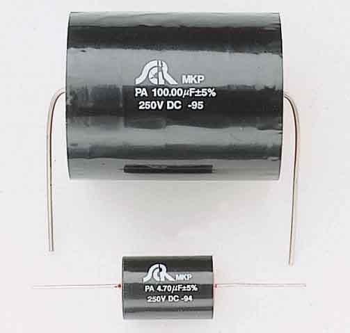
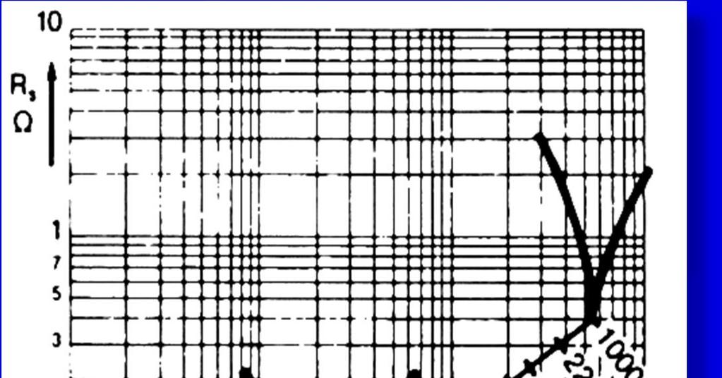
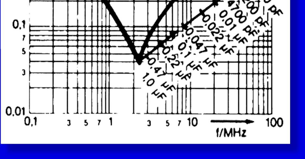
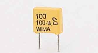
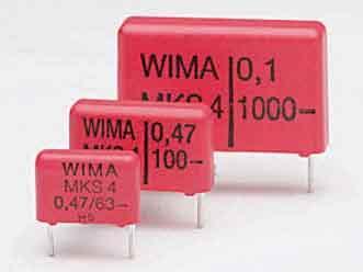
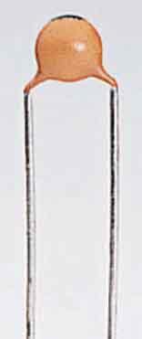
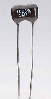


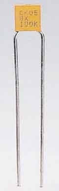
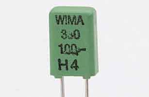
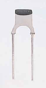


25 Capacitors high-frequency model Z R ESR capacitive f SRF inductive f R ESR = equivalent series resistance Johan Wernehag, EIT RF Amplifier Design ETIN50 - Lecture 4 26
26 Capacitor Frequency characteristics - example Z R = 2W L = 1nH C = 1pF C p = 100fF C R L C p f [Hz] Johan Wernehag, EIT RF Amplifier Design ETIN50 - Lecture 4 27
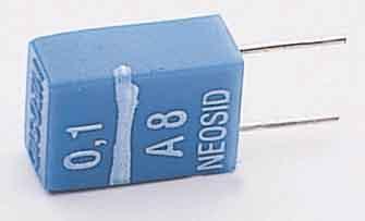

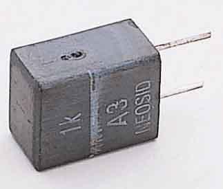

27 Inductors high-frequency model Z R P inductive f SRF capacitive f R P = equivalent parallel resistance Johan Wernehag, EIT RF Amplifier Design ETIN50 - Lecture 4 28
28 Inductor Frequency characteristics - example Z R = 3W L = 5nH C p = 100fF R L C f [Hz] Johan Wernehag, EIT RF Amplifier Design ETIN50 - Lecture 4 29
29 Inductor Q = X R S The Q-factor frequency dependence Q X T = wl R ~ w R ~ X T The losses increases rapidly versus the frequency X T = wl R = R DC SRF (self resonance frequency) X T = total reactance of the inductor Skin effect Parasitic capacitance ω C parasitic doesn t affect the Q if the inductor is used in a resonant circuit! Johan Wernehag, EIT RF Amplifier Design ETIN50 - Lecture 4 30

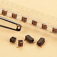
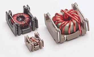
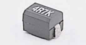
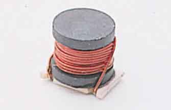
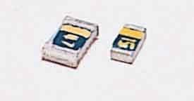
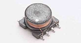
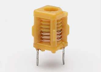
30 Transformer Windings on a ferrite rod or toroid core These materials provides a high permeability that unfortunately decreases at higher frequencies Usable at best up to a few GHz Johan Wernehag, EIT RF Amplifier Design ETIN50 - Lecture 4 31
31 Loss in Substrate Materials For dielectric materials often the loss tangent used to specify the losses: tand = s we for material with low loss tand» d where d is the loss angle The loss tangent is also related to the quality factor or Q-factor of the material: tand = 1 Q d Johan Wernehag, EIT RF Amplifier Design ETIN50 - Lecture 4 32
32 Properties of some Substrate Materials Material r tan Ceramic Beryllium oxide Duorid Teflon fibre-glass Silicon Quarz Epoxy fibre-glass Aluminium oxide Johan Wernehag, EIT RF Amplifier Design ETIN50 - Lecture 4 33
33 Properties of some Metals Metal [S/m] Aluminium Copper Gold Iron Silver Johan Wernehag, EIT RF Amplifier Design ETIN50 - Lecture 4 34
34 Skin Effect The magnetic flux inside the conductor will effectively push the current to a narrow region close to the surface z Current density d i J e J 0 J 2 Skin depth: d = the distance were the current density i = wms has decreased by a factor e A large circumference is more essential than a large cross section area of the conductor! Johan Wernehag, EIT RF Amplifier Design ETIN50 - Lecture 4 35
35 Example of Skin Depth d i [m] - - iron aluminium gold copper silver f [Hz] Johan Wernehag, EIT RF Amplifier Design ETIN50 - Lecture 4 36
36 Dimension of the Coaxial Cable Z ε = 1 (air) ε D ,0 1,2 1,4 1,6 1,8 2 2, æ è ç D d ö ø d Z 0 = 138 e r log 10 æ è ç = 60 æ ln D e r è ç d ö ø D d ö ø = Johan Wernehag, EIT RF Amplifier Design ETIN50 - Lecture 4 37

37 Microstrip Cross section of a microstrip structure W h H E å r ground plane Complex geometry and non-uniform fields makes a complicated flux image. e r in the substrate is therefore not usable for calculation of for example electrical length in the line structure. Instead the effective permittivity, e eff, based on the dimensions of the microstrip structure, may be used. Johan Wernehag, EIT RF Amplifier Design ETIN50 - Lecture 4 38
38 Design of Microstrip, Diagram 1 Determine the proper W for a specified Z 0 and h Z e r - W/h Johan Wernehag, EIT RF Amplifier Design ETIN50 - Lecture 4 39
39 Design of Microstrip, Diagram 2 Determine the effective permittivity e eff e eff e r W/h Johan Wernehag, EIT RF Amplifier Design ETIN50 - Lecture 4 40
40 Design of Microstrip, Summary Specified Z 0, substrate height h and permittivity ε r : Z 0 1. Select the width W in diagram 1 e r 2. Select the effective permittivity ε eff in diagram 2 e eff W/h 3. Calculate the effective wavelength l eff = l 0 e eff e r W/h Specified electrical length l el 4. Calculate the physical length l = l el l eff Johan Wernehag, EIT RF Amplifier Design ETIN50 - Lecture 4 41
41 Stripline W ground plane substrate e r conductor h ground plane Johan Wernehag, EIT RF Amplifier Design ETIN50 - Lecture 4 42
42 Discontinuities The design of circuits containing transmission lines must take into account the impact of junctions and transitions between different line widths. circuit diagram design Z 0,1 Z 0,1 l 1 l 1 l 2 l 3 l 3 Z 0,2 l 2 How to model such a geometry? Johan Wernehag, EIT RF Amplifier Design ETIN50 - Lecture 4 43
43 Discontinuities (cont.) T-junction, equivalent model Z 0, 1 Z 0, 1 Z 0, 2 Methods for manual calculation of the circuit elements in the equivalent model may be found in handbooks. Johan Wernehag, EIT RF Amplifier Design ETIN50 - Lecture 4 44
44 Discontinuities (cont.) Symmetrical step, an abrupt transition between two different line widths W 1 W Z 2 0, 1 Z 0, 2 Transmission line, open-circuit termination conductor C f ground plane e r e r Johan Wernehag, EIT RF Amplifier Design ETIN50 - Lecture 4 45
45 Discontinuities (cont.) Some other cases are corners and bends serial gap (to realize a serial capacitance) undesired coupling between nearby structures Crosstalk CAD tools are necessary for analysis and design of more complex circuits ADS and others In worst case a complete structure may be simulated by the finite element method and Maxwell s equations which is both time and memory consuming Johan Wernehag, EIT RF Amplifier Design ETIN50 - Lecture 4 46
Lecture 4. Maximum Transfer of Power. The Purpose of Matching. Lecture 4 RF Amplifier Design. Johan Wernehag Electrical and Information Technology
 Johan Wernehag, EIT Lecture 4 RF Amplifier Design Johan Wernehag Electrical and Information Technology Design of Matching Networks Various Purposes of Matching Voltage-, Current- and Power Matching Design
EC Transmission Lines And Waveguides
 EC6503 - Transmission Lines And Waveguides UNIT I - TRANSMISSION LINE THEORY A line of cascaded T sections & Transmission lines - General Solution, Physical Significance of the Equations 1. Define Characteristic
RF Devices and RF Circuit Design for Digital Communication
 RF Devices and RF Circuit Design for Digital Communication Agenda Fundamentals of RF Circuits Transmission ine Reflection Coefficient & Smith Chart Impedance Matching S-matrix Representation Amplifiers
RF Devices and RF Circuit Design for Digital Communication
 RF Devices and RF Circuit Design for Digital Communication Agenda Fundamentals of RF Circuits Transmission ine Reflection Coefficient & Smith Chart Impedance Matching S-matrix Representation Amplifiers
Γ L = Γ S =
 TOPIC: Microwave Circuits Q.1 Determine the S parameters of two port network consisting of a series resistance R terminated at its input and output ports by the characteristic impedance Zo. Q.2 Input matching
Microwave Engineering
 Microwave Circuits 1 Microwave Engineering 1. Microwave: 300MHz ~ 300 GHz, 1 m ~ 1mm. a. Not only apply in this frequency range. The real issue is wavelength. Historically, as early as WWII, this is the
Lecture 9 RF Amplifier Design. Johan Wernehag, EIT. Johan Wernehag Electrical and Information Technology
 Lecture 9 RF Amplifier Design Johan Wernehag Electrical and Information Technology Lecture 9 Oscillators Oscillators Based on Feedback Requirements for Self-Oscillation Output Power and Harmonic Distortion
Microwave and RF Engineering
 Microwave and RF Engineering Volume 1 An Electronic Design Automation Approach Ali A. Behagi and Stephen D. Turner BT Microwave LLC State College, PA 16803 Copyrighted Material Microwave and RF Engineering
What is a matching network?
 Impedance Matching and Tuning Matching networks are used to match the impedance of one system to another Match is important for several reasons: Provides for maximum power transfer (e.g. carrying power
Chapter 4 Impedance Matching
 Chapter 4 Impedance Matching Quarter-wave transformer, series section transformer Stub matching, lumped element networks, feed point location 3 Gamma match 4 Delta- and T-match, Baluns -port network Smith
Radio Frequency Electronics
 Radio Frequency Electronics Preliminaries IV Born 22 February 1857, died 1 January 1894 Physicist Proved conclusively EM waves (theorized by Maxwell ), exist. Hz names in his honor. Created the field of
Design and Simulation of Folded Arm Miniaturized Microstrip Low Pass Filter
 813 Design and Simulation of Folded Arm Miniaturized Microstrip Low Pass 1 Inder Pal Singh, 2 Praveen Bhatt 1 Shinas College of Technology P.O. Box 77, PC 324, Shinas, Oman 2 Samalkha Group of Institutions,
Transmission Lines. Ranga Rodrigo. January 27, Antennas and Propagation: Transmission Lines 1/72
 Transmission Lines Ranga Rodrigo January 27, 2009 Antennas and Propagation: Transmission Lines 1/72 1 Standing Waves 2 Smith Chart 3 Impedance Matching Series Reactive Matching Shunt Reactive Matching
Microwave Devices and Circuit Design
 Microwave Devices and Circuit Design Ganesh Prasad Srivastava Vijay Laxmi Gupta MICROWAVE DEVICES and CIRCUIT DESIGN GANESH PRASAD SRIVASTAVA Professor (Retired) Department of Electronic Science University
ECE 145A and 218A. Transmission-line properties, impedance-matching exercises
 ECE 145A and 218A. Transmission-line properties, impedance-matching exercises Problem #1 This is a circuit file to study a transmission line. The 2 resistors are included to allow easy disconnection of
Microwave and RF Engineering
 Microwave and RF Engineering A Simulation Approach with Keysight Genesys Software Chapter 4: Resonant Circuits and Filters Ali A. Behagi Stephen D. Turner Microwave and RF Engineering A Simulation Approach
Equivalent Circuit Model Overview of Chip Spiral Inductors
 Equivalent Circuit Model Overview of Chip Spiral Inductors The applications of the chip Spiral Inductors have been widely used in telecommunication products as wireless LAN cards, Mobile Phone and so on.
EC TRANSMISSION LINES AND WAVEGUIDES TRANSMISSION LINES AND WAVEGUIDES
 TRANSMISSION LINES AND WAVEGUIDES UNIT I - TRANSMISSION LINE THEORY 1. Define Characteristic Impedance [M/J 2006, N/D 2006] Characteristic impedance is defined as the impedance of a transmission line measured
Today s Topic: More Lumped-Element. Circuit Models
 Today s Topic: More Lumped-Element Recall: Circuit Models We discussed a wire (inductor), resistor (series L, parallel RC) last time Plan: round out our library of components Capacitor, inductor Examine
Waveguides. Metal Waveguides. Dielectric Waveguides
 Waveguides Waveguides, like transmission lines, are structures used to guide electromagnetic waves from point to point. However, the fundamental characteristics of waveguide and transmission line waves
Texas Instruments DisplayPort Design Guide
 Texas Instruments DisplayPort Design Guide April 2009 1 High Speed Interface Applications Introduction This application note presents design guidelines, helping users of Texas Instruments DisplayPort devices
INF 5490 RF MEMS. LN12: RF MEMS inductors. Spring 2011, Oddvar Søråsen Department of informatics, UoO
 INF 5490 RF MEMS LN12: RF MEMS inductors Spring 2011, Oddvar Søråsen Department of informatics, UoO 1 Today s lecture What is an inductor? MEMS -implemented inductors Modeling Different types of RF MEMS
SEMICONDUCTOR AN548A MICROSTRIP DESIGN TECHNIQUES FOR UHF AMPLIFIERS MOTOROLA APPLICATION NOTE INTRODUCTION MICROSTRIP DESIGN CONSIDERATIONS
 MOTOROLA SEMICONDUCTOR APPLICATION NOTE Order this document by AN548A/D AN548A DESIGN TECHNIQUES FOR UHF AMPLIFIERS Prepared by: Glenn Young INTRODUCTION This note uses a 25 watt UHF amplifier design as
Full wave analysis of non-radiative dielectric waveguide modulator for the determination of electrical equivalent circuit
 PRAMANA c Indian Academy of Sciences Vol. 71, No. 1 journal of July 2008 physics pp. 65 75 Full wave analysis of non-radiative dielectric waveguide modulator for the determination of electrical equivalent
Lowpass and Bandpass Filters
 Microstrip Filters for RF/Microwave Applications. Jia-Sheng Hong, M. J. Lancaster Copyright 2001 John Wiley & Sons, Inc. ISBNs: 0-471-38877-7 (Hardback); 0-471-22161-9 (Electronic) CHAPTER 5 Lowpass and
Schematic-Level Transmission Line Models for the Pyramid Probe
 Schematic-Level Transmission Line Models for the Pyramid Probe Abstract Cascade Microtech s Pyramid Probe enables customers to perform production-grade, on-die, full-speed test of RF circuits for Known-Good
Optically reconfigurable balanced dipole antenna
 Loughborough University Institutional Repository Optically reconfigurable balanced dipole antenna This item was submitted to Loughborough University's Institutional Repository by the/an author. Citation:
Categorized by the type of core on which inductors are wound:
 Inductors Categorized by the type of core on which inductors are wound: air core and magnetic core. The magnetic core inductors can be subdivided depending on whether the core is open or closed. Equivalent
EC6503 Transmission Lines and WaveguidesV Semester Question Bank
 UNIT I TRANSMISSION LINE THEORY A line of cascaded T sections & Transmission lines General Solution, Physicasignificance of the equations 1. Derive the two useful forms of equations for voltage and current
Exercises for the Antenna Matching Course
 Exercises for the Antenna Matching Course Lee Vishloff, PEng, IEEE WCP C-160302-1 RELEASE 1 Notifications 2016 Services, Inc. All rights reserved. The and Services Inc. stylized text belongs to tech-knows
Design of a Cylindrical Cavity Resonator for Measurements of Electrical Properties of Dielectric Materials
 DEPARTMENT OF TECHNOLOGY Design of a Cylindrical Cavity Resonator for Measurements of Electrical Properties of Dielectric Materials Xiang Li, Yan Jiang September-2010 Master Thesis in Electronics/Telecommunications
VLSI is scaling faster than number of interface pins
 High Speed Digital Signals Why Study High Speed Digital Signals Speeds of processors and signaling Doubled with last few years Already at 1-3 GHz microprocessors Early stages of terahertz Higher speeds
High Frequency Passive Components
 EECS 142 Laboratory #1 High Frequency Passive Components Prof. A. M. Niknejad and Dr. Joel Dunsmore University of California Berkeley, CA 94720 August 1, 2008 1 SMT Component SMA Connector 1 Introduction
Chapter-2 LOW PASS FILTER DESIGN 2.1 INTRODUCTION
 Chapter-2 LOW PASS FILTER DESIGN 2.1 INTRODUCTION Low pass filters (LPF) are indispensable components in modern wireless communication systems especially in the microwave and satellite communication systems.
CHAPTER 5 PRINTED FLARED DIPOLE ANTENNA
 CHAPTER 5 PRINTED FLARED DIPOLE ANTENNA 5.1 INTRODUCTION This chapter deals with the design of L-band printed dipole antenna (operating frequency of 1060 MHz). A study is carried out to obtain 40 % impedance
Lowpass Filters. Microwave Filter Design. Chp5. Lowpass Filters. Prof. Tzong-Lin Wu. Department of Electrical Engineering National Taiwan University
 Microwave Filter Design Chp5. Lowpass Filters Prof. Tzong-Lin Wu Department of Electrical Engineering National Taiwan University Lowpass Filters Design steps Select an appropriate lowpass filter prototype
ELC 4383 RF/Microwave Circuits I Laboratory 4: Quarter-Wave Impedance Matching Network
 1 ELC 4383 RF/Microwave Circuits I Laboratory 4: Quarter-Wave Impedance Matching Network Note: This lab procedure has been adapted from a procedure written by Dr. Larry Dunleavy and Dr. Tom Weller at the
Impedance Matching Techniques for Mixers and Detectors. Application Note 963
 Impedance Matching Techniques for Mixers and Detectors Application Note 963 Introduction The use of tables for designing impedance matching filters for real loads is well known [1]. Simple complex loads
University of KwaZulu-Natal
 University of KwaZulu-Natal School of Engineering Electrical, Electronic & Computer Engineering Instructions to Candidates: UNIVERSITY EXAMINATIONS DECEMBER 2016 ENEL3EM: EM THEORY Time allowed: 2 hours
Basic MODAMP MMIC Circuit Techniques. Application Note S001
 Basic MODAMP MMIC Circuit Techniques Application Note S001 Introduction and MODAMP MMIC Structure Agilent Technologies MSA (Monolithic Silicon Amplifier) series MODAMP silicon bipolar Monolithic Microwave
Microwave Engineering Third Edition
 Microwave Engineering Third Edition David M. Pozar University of Massachusetts at Amherst WILEY John Wiley & Sons, Inc. ELECTROMAGNETIC THEORY 1 1.1 Introduction to Microwave Engineering 1 Applications
Modeling and Simulation of Via Conductor Losses in Co-fired Ceramic Substrates Used In Transmit/Receive Radar Modules
 Modeling and Simulation of Via Conductor Losses in Co-fired Ceramic Substrates Used In Transmit/Receive Radar Modules 4/5/16 Rick Sturdivant, CTO 310-980-3039 rick@rlsdesigninc.com Edwin K.P. Chong, Professor
APPLIED ELECTROMAGNETICS: EARLY TRANSMISSION LINES APPROACH
 APPLIED ELECTROMAGNETICS: EARLY TRANSMISSION LINES APPROACH STUART M. WENTWORTH Auburn University IICENTBN Nlfll 1807; WILEY 2 OO 7 ; Ttt^TlLtftiTTu CONTENTS CHAPTER1 Introduction 1 1.1 1.2 1.3 1.4 1.5
Radio Frequency Electronics
 Radio Frequency Electronics Preliminaries II Guglielmo Giovanni Maria Marconi Thought off by many people as the inventor of radio Pioneer in long-distance radio communications Shared Nobel Prize in 1909
100 Genesys Design Examples
 [Type here] [Type here] [Type here] 100 Genesys Design Examples A Design Approach using (Genesys): Chapter 2: Transmission Line Components Ali Behagi 100 Genesys Design Examples A Design Approach using
RF AND MICROWAVE ENGINEERING
 RF AND MICROWAVE ENGINEERING FUNDAMENTALS OF WIRELESS COMMUNICATIONS Frank Gustrau Dortmund University of Applied Sciences and Arts, Germany WILEY A John Wiley & Sons, Ltd., Publication Preface List of
ECEN 5014, Spring 2009 Special Topics: Active Microwave Circuits Zoya Popovic, University of Colorado, Boulder
 ECEN 5014, Spring 2009 Special Topics: Active Microwave Circuits Zoya opovic, University of Colorado, Boulder LECTURE 3 MICROWAVE AMLIFIERS: INTRODUCTION L3.1. TRANSISTORS AS BILATERAL MULTIORTS Transistor
New Configurations for RF/Microwave Filters
 New Configurations for RF/Microwave Filters Presented by: Jeremy Fejfar Applications Engineer CST of America, Inc. 1 www.cst.com Sep-06 Outline Introduction Conventional Filter Theory Need for Folded Transmission
What is an Inductor? Token Electronics Industry Co., Ltd. Version: January 16, Web:
 Version: January 16, 2017 What is an Inductor? Web: www.token.com.tw Email: rfq@token.com.tw Token Electronics Industry Co., Ltd. Taiwan: No.137, Sec. 1, Zhongxing Rd., Wugu District, New Taipei City,
Introduction: Planar Transmission Lines
 Chapter-1 Introduction: Planar Transmission Lines 1.1 Overview Microwave integrated circuit (MIC) techniques represent an extension of integrated circuit technology to microwave frequencies. Since four
Microstrip Line Discontinuities Simulation at Microwave Frequencies
 Microstrip Line Discontinuities Simulation at Microwave Frequencies Dr. A.K. Rastogi 1* (FIETE), (MISTE), Munira Bano 1, Manisha Nigam 2 1. Department of Physics & Electronics, Institute for Excellence
A WIRELESS ENERGY HARVESTING SYSTEM WITH BEAMFORMING CAPABILITIES
 A WIRELESS ENERGY HARVESTING SYSTEM WITH BEAMFORMING CAPABILITIES by Daniel Schemmel A thesis submitted to the Faculty and the Board of Trustees of the Colorado School of Mines in partial fulfillment of
Ensuring Signal and Power Integrity for High-Speed Digital Systems
 Ensuring Signal and Power Integrity for High-Speed Digital Systems An EMC Perspective Christian Schuster Institut für Theoretische Elektrotechnik Technische Universität Hamburg-Harburg (TUHH) Invited Presentation
Design of Duplexers for Microwave Communication Systems Using Open-loop Square Microstrip Resonators
 International Journal of Electromagnetics and Applications 2016, 6(1): 7-12 DOI: 10.5923/j.ijea.20160601.02 Design of Duplexers for Microwave Communication Charles U. Ndujiuba 1,*, Samuel N. John 1, Taofeek
800 MHz Test Fixture Design
 Application Note Rev. 0, 7/993 NOTE: The theory in this application note is still applicable, but some of the products referenced may be discontinued. 800 MHz Test Fixture Design By: Dan Moline Although
Outcomes: Core Competencies for ECE145A/218A
 Outcomes: Core Competencies for ECE145A/18A 1. Transmission Lines and Lumped Components 1. Use S parameters and the Smith Chart for design of lumped element and distributed L matching networks. Able to
Loop and Slot Antennas
 Loop and Slot Antennas Prof. Girish Kumar Electrical Engineering Department, IIT Bombay gkumar@ee.iitb.ac.in (022) 2576 7436 Loop Antenna Loop antennas can have circular, rectangular, triangular or any
Application Note 5525
 Using the Wafer Scale Packaged Detector in 2 to 6 GHz Applications Application Note 5525 Introduction The is a broadband directional coupler with integrated temperature compensated detector designed for
MICROSTRIP AND WAVEGUIDE PASSIVE POWER LIMITERS WITH SIMPLIFIED CONSTRUCTION
 Journal of Microwaves and Optoelectronics, Vol. 1, No. 5, December 1999. 14 MICROSTRIP AND WAVEGUIDE PASSIVE POWER IMITERS WITH SIMPIFIED CONSTRUCTION Nikolai V. Drozdovski & ioudmila M. Drozdovskaia ECE
Radio Frequency Electronics
 Radio Frequency Electronics Preliminaries III Lee de Forest Born in Council Bluffs, Iowa in 1873 Had 180 patents Invented the vacuum tube that allows for building electronic amplifiers Vacuum tube started
A WIDEBAND RECTANGULAR MICROSTRIP ANTENNA WITH CAPACITIVE FEEDING
 A WIDEBAND RECTANGULAR MICROSTRIP ANTENNA WITH CAPACITIVE FEEDING Hind S. Hussain Department of Physics, College of Science, Al-Nahrain University, Baghdad, Iraq E-Mail: hindalrawi@yahoo.com ABSTRACT A
University of Pennsylvania Moore School of Electrical Engineering ESE319 Electronic Circuits - Modeling and Measurement Techniques
 University of Pennsylvania Moore School of Electrical Engineering ESE319 Electronic Circuits - Modeling and Measurement Techniques 1. Introduction. Students are often frustrated in their attempts to execute
EKT 356 MICROWAVE COMMUNICATIONS CHAPTER 4: MICROWAVE FILTERS
 EKT 356 MICROWAVE COMMUNICATIONS CHAPTER 4: MICROWAVE FILTERS 1 INTRODUCTION What is a Microwave filter? linear 2-port network controls the frequency response at a certain point in a microwave system provides
Physical RF Circuit Techniques and Their Implications on Future Power Module and Power Electronic Design
 Physical RF Circuit Techniques and Their Implications on Future Power Module and Power Electronic Design Adam Morgan 5-5-2015 NE IMAPS Symposium 2015 Overall Motivation Wide Bandgap (WBG) semiconductor
Investigation of a Voltage Probe in Microstrip Technology
 Investigation of a Voltage Probe in Microstrip Technology (Specifically in 7-tesla MRI System) By : Mona ParsaMoghadam Supervisor : Prof. Dr. Ing- Klaus Solbach April 2015 Introduction - Thesis work scope
Chapter 2. Modified Rectangular Patch Antenna with Truncated Corners. 2.1 Introduction of rectangular microstrip antenna
 Chapter 2 Modified Rectangular Patch Antenna with Truncated Corners 2.1 Introduction of rectangular microstrip antenna 2.2 Design and analysis of rectangular microstrip patch antenna 2.3 Design of modified
Chapter 2 Displaying Characteristics
 Chapter 2 Displaying Characteristics Impedance Characteristics of Chip Beads Chip beads are parts used to prevent EMI and control decoupling of LSI power source lines and to control over/under shooting
Application Note A008
 Microwave Oscillator Design Application Note A008 Introduction This application note describes a method of designing oscillators using small signal S-parameters. The background theory is first developed
Agilent How To Accurately Evaluate Low ESR, High Q RF Chip Devices. Application Note
 Agilent How To Accurately Evaluate Low ESR, High Q RF Chip Devices Application Note 1369-6 Contents The Changing Requirements of RF Component Testing............ 3 Measurement challenges...................................
University of KwaZulu-Natal
 University of KwaZulu-Natal School of Engineering Electrical, Electronic & Computer Engineering UNIVERSITY EXAMINATIONS NOVEMBER 2015 ENEL3EM: EM THEORY Time allowed: 2 hours Instructions to Candidates:
Chapter 2. The Fundamentals of Electronics: A Review
 Chapter 2 The Fundamentals of Electronics: A Review Topics Covered 2-1: Gain, Attenuation, and Decibels 2-2: Tuned Circuits 2-3: Filters 2-4: Fourier Theory 2-1: Gain, Attenuation, and Decibels Most circuits
Exercise problems of topic 1: Transmission line theory and typical waveguides
 Exercise problems of topic 1: Transmission line theory and typical waveguides Return your answers in the contact sessions on a paper; either handwritten or typescripted. You can return them one by one.
ELC 4396 RF/Microwave Circuits I Fall 2011 Final Exam December 9, 2011 Open Book/Open Notes 2 hours
 Name ELC 4396 RF/Microwave Circuits I Fall 2011 Final Exam December 9, 2011 Open Book/Open Notes 2 hours 1. The exam is open-book/open-notes. 2. A calculator may be used to assist with the test. No laptops
Antennas Prof. Girish Kumar Department of Electrical Engineering Indian Institute of Technology, Bombay. Module 2 Lecture - 10 Dipole Antennas-III
 Antennas Prof. Girish Kumar Department of Electrical Engineering Indian Institute of Technology, Bombay Module 2 Lecture - 10 Dipole Antennas-III Hello, and welcome to todays lecture on Dipole Antenna.
RF Circuit Synthesis for Physical Wireless Design
 RF Circuit Synthesis for Physical Wireless Design Overview Subjects Review Of Common Design Tasks Break Down And Dissect Design Task Review Non-Synthesis Methods Show A Better Way To Solve Complex Design
Efficient Electromagnetic Analysis of Spiral Inductor Patterned Ground Shields
 Efficient Electromagnetic Analysis of Spiral Inductor Patterned Ground Shields James C. Rautio, James D. Merrill, and Michael J. Kobasa Sonnet Software, North Syracuse, NY, 13212, USA Abstract Patterned
 VALLIAMMAI ENGINEERING COLLEGE SRM Nagar, Kattankulathur-603 203 DEPARTMENT OF ELECTRONICS AND COMMUNICATION ENGINEERING EC6503 TRANSMISSION LINES AND WAVEGUIDES YEAR / SEMESTER: III / V ACADEMIC YEAR:
Homework Assignment 05
 Homework Assignment 05 Question (2 points each unless otherwise indicated)(20 points). Estimate the parallel parasitic capacitance of a mh inductor with an SRF of 220 khz. Answer: (2π)(220 0 3 ) = ( 0
Today I would like to present a short introduction to microstrip cross-coupled filter design. I will be using Sonnet em to analyze my planar circuit.
 Today I would like to present a short introduction to microstrip cross-coupled filter design. I will be using Sonnet em to analyze my planar circuit. And I will be using our optimizer, EQR_OPT_MWO, in
ELECTROMAGNETIC COMPATIBILITY HANDBOOK 1. Chapter 8: Cable Modeling
 ELECTROMAGNETIC COMPATIBILITY HANDBOOK 1 Chapter 8: Cable Modeling Related to the topic in section 8.14, sometimes when an RF transmitter is connected to an unbalanced antenna fed against earth ground
Demystifying Vias in High-Speed PCB Design
 Demystifying Vias in High-Speed PCB Design Keysight HSD Seminar Mastering SI & PI Design db(s21) E H What is Via? Vertical Interconnect Access (VIA) An electrical connection between layers to pass a signal
Lecture 9 - Lumped Element Matching Networks
 Lecture 9 - Lumped Element Matching Networks Microwave Active Circuit Analysis and Design Clive Poole and Izzat Darwazeh Academic Press Inc. Poole-Darwazeh 2015 Lecture 9 - Lumped Element Matching Networks
Methodology for MMIC Layout Design
 17 Methodology for MMIC Layout Design Fatima Salete Correra 1 and Eduardo Amato Tolezani 2, 1 Laboratório de Microeletrônica da USP, Av. Prof. Luciano Gualberto, tr. 3, n.158, CEP 05508-970, São Paulo,
Chapter 7 RF Filters
 RF Electronics Chapter 7: RF Filters Page 1 Introduction Chapter 7 RF Filters Filters used for RF signals are nearly always Bandpass filters using coupled resonator design techniques. The basic properties
Advanced Transmission Lines. Transmission Line 1
 Advanced Transmission Lines Transmission Line 1 Transmission Line 2 1. Transmission Line Theory :series resistance per unit length in. :series inductance per unit length in. :shunt conductance per unit
A NOVEL DUAL-BAND BANDPASS FILTER USING GENERALIZED TRISECTION STEPPED IMPEDANCE RESONATOR WITH IMPROVED OUT-OF-BAND PER- FORMANCE
 Progress In Electromagnetics Research Letters, Vol. 21, 31 40, 2011 A NOVEL DUAL-BAND BANDPASS FILTER USING GENERALIZED TRISECTION STEPPED IMPEDANCE RESONATOR WITH IMPROVED OUT-OF-BAND PER- FORMANCE X.
Lecture 7: Transmission Line Matching Using Lumped L Networks.
 Whites, EE 48/58 ecture 7 Page of ecture 7: Transmission ine Matching Using umped Networks. Impedance matching (or simply matching ) one portion of a circuit to another is an immensely important part of
A VIEW OF ELECTROMAGNETIC LIFE ABOVE 100 MHz
 A VIEW OF ELECTROMAGNETIC LIFE ABOVE 100 MHz An Experimentalist's Intuitive Approach Lothar O. (Bud) Hoeft, PhD Consultant, Electromagnetic Effects 5012 San Pedro Ct., NE Albuquerque, NM 87109-2515 (505)
AXIEM White Paper. Modeling a Printed VHF Balun Leveraging EM Simulation Techniques INTRODUCTION
 AXIEM White Paper INTRODUCTION The use of printed microstrip couplers in power amplifiers operating at microwave frequencies above 1GHz has been well established and numerous papers have been written about
Chapter 5 DESIGN AND IMPLEMENTATION OF SWASTIKA-SHAPED FREQUENCY RECONFIGURABLE ANTENNA ON FR4 SUBSTRATE
 Chapter 5 DESIGN AND IMPLEMENTATION OF SWASTIKA-SHAPED FREQUENCY RECONFIGURABLE ANTENNA ON FR4 SUBSTRATE The same geometrical shape of the Swastika as developed in previous chapter has been implemented
Integrated Circuits: FABRICATION & CHARACTERISTICS - 4. Riju C Issac
 Integrated Circuits: FABRICATION & CHARACTERISTICS - 4 Riju C Issac INTEGRATED RESISTORS Resistor in a monolithic IC is very often obtained by the bulk resistivity of one of the diffused areas. P-type
Research Article Compact and Wideband Parallel-Strip 180 Hybrid Coupler with Arbitrary Power Division Ratios
 Microwave Science and Technology Volume 13, Article ID 56734, 1 pages http://dx.doi.org/1.1155/13/56734 Research Article Compact and Wideband Parallel-Strip 18 Hybrid Coupler with Arbitrary Power Division
Case Study: Parallel Coupled-Line Combline Filter. Microwave filter design. Specifications. Case Study: Parallel Coupled- Line Combline Filter
 MIROWAVE AND RF DESIGN MIROWAVE AND RF DESIGN ase Study: Parallel oupled- ine ombline Filter ase Study: Parallel oupled-ine ombline Filter Presented by Michael Steer Reading: 6. 6. 5 b t b 5 S (db) 6 S
Ferrites for High Frequency Noise Suppression Chapter 9
 TMPST ngineering and Hardware Design Dr. Bruce C. abrielson, NC 1998 Ferrites for High Frequency Noise Suppression Chapter 9 Introduction The drive for higher speed devices and the proliferation of widespread
Foundations of Interconnect and Microstrip Design
 Foundations of Interconnect and Microstrip Design Third Edition T. C. Edwards and M. B. Steer Engalco and University of Leeds, North Carolina State University JOHN WILEY & SONS Chichester. New York. Brisbane.
SELF-RESONANCE IN COILS and the self-capacitance myth
 SELF-RESONANCE IN COILS and the self-capacitance myth All coils show a self-resonant frequency (SRF), and as this frequency is approached the inductance and resistance increase while the Q decreases until
Transformation of Generalized Chebyshev Lowpass Filter Prototype to Suspended Stripline Structure Highpass Filter for Wideband Communication Systems
 Transformation of Generalized Chebyshev Lowpass Filter Prototype to Suspended Stripline Structure Highpass Filter for Wideband Communication Systems Z. Zakaria 1, M. A. Mutalib 2, M. S. Mohamad Isa 3,
ON-CHIP TECHNOLOGY INDEPENDENT 3-D MOD- ELS FOR MILLIMETER-WAVE TRANSMISSION LINES WITH BEND AND GAP DISCONTINUITY
 Progress In Electromagnetics Research B, Vol. 22, 171 185, 2010 ON-CHIP TECHNOLOGY INDEPENDENT 3-D MOD- ELS FOR MILLIMETER-WAVE TRANSMISSION LINES WITH BEND AND GAP DISCONTINUITY G. A. Wang, W. Woods,
Introduction to Electromagnetic Compatibility
 Introduction to Electromagnetic Compatibility Second Edition CLAYTON R. PAUL Department of Electrical and Computer Engineering, School of Engineering, Mercer University, Macon, Georgia and Emeritus Professor
Freescale Semiconductor, I
 nc. SEMICONDUCTOR APPLICATION NOTE Order this document by AN548A/D Prepared by: Glenn Young INTRODUCTION This note uses a 25 watt UHF amplifier design as a vehicle to discuss microstrip design techniques.