How to Design Good PDN Filters
|
|
|
- Tyrone Wilkins
- 5 years ago
- Views:
Transcription


1 How to Design Good PDN Filters Istvan Novak, Samtec This session was presented as part of the DesignCon 2019 Conference and Expo. For more information on the event, please go to DesignCon.com 1
2 How to Design Good PDN Filters Istvan Novak, (Samtec) January 29-31,

3 SPEAKER Istvan Novak Principle Signal and Power Integrity Engineer Istvan Novak is a Principle Signal and Power Integrity Engineer at Samtec, working on advanced signal and power integrity designs. Prior to 2018 he was a Distinguished Engineer at SUN Microsystems, later Oracle. He worked on new technology development, advanced power distribution and signal integrity design and validation methodologies for SUN's successful workgroup server families. He introduced the industry's first 25um power-ground laminates for large rigid computer boards, and worked with component vendors to create a series of low-inductance and controlled- ESR bypass capacitors. He also served as SUN's representative on the Copper Cable and Connector Workgroup of InfiniBand, and was engaged in the methodologies, designs and characterization of power-distribution networks from silicon to DC-DC converters. He is a Life Fellow of the IEEE with twenty-five patents to his name, author of two books on power integrity, teaches signal and power integrity courses, and maintains a popular SI/PI website. January 29-31,
4 OUTLINE * Introduction, scope * Requirements * Filter design procedure * What can go wrong Wrong layout Bias dependence * Simulations and correlations * Demos January 29-31,
5 OUTLINE * Introduction, scope * Requirements * Filter design procedure * What can go wrong Wrong layout Bias dependence * Simulations and correlations * Demos January 29-31,
6 What This Is and What This Is NOT * This tutorial is NOT about all-parallel bypassing * This tutorial is about PDN structures where series elements (whether intentionally placed or accidentally being in the circuit) matter for the performance Ferritebead Lf1 Lf2 Input Rdc Rf1 Rf2 Output C1 C2 C3 Cb Rb C4 C5 C6 R1 R2 R3 R4 R5 R6 L1 L2 L3 L4 L5 L6 January 29-31,
7 When We Need a Filter To feed a sensitive low-current load Primary supply side: 3.3V 10A, 200mVpp noise Filtered secondary supply: 3.3V 0.1A, 2mVpp noise DC DC It is easier to filter AC PDN filter AC Lowjitter clock source for a low-current rail than quiet a high-current rail. January 29-31,
8 When We Need a Filter To keep noise spilling out from noisy loads Quieter primary supply side Noisy secondary supply DC AC PDN filter AC DC High-current noisy DC-DC converter input It is easier to contain noise at its source. Main stress parameter is capacitor ripple current. January 29-31,


9 Typical Noise Source * DC-DC converters are popular and needed for their high efficiency * They tend to generate a lot of noise January 29-31,

T v = ESR* I T time January")
10 DC-DC Converter Output Ripple Voltage The inductor ripple current flows through the output capacitor DC DC First-order mid-frequency capacitor model = ESR-only Output ripple voltage shape closely follows inductor ripple current AC PDN filter AC Lowjitter clock source v out (t) v load v If Cload*ESR pole is below Fsw, the output ripple is: DT (1-D)T v = ESR* I T time January 29-31,
11 DC-DC Converter Output Ripple Voltage The inductor ripple current flows through the output capacitor First-order midfrequency capacitor model = ESR-only Output ripple voltage shape closely follows inductor ripple current January 29-31,

 time I load January 29-31, 2019 12")
12 DC-DC Converter Input I in * The input voltage is chopped by the switches I load * Inductor current is continuous * Input current has large jumps v SW (t) V in DC DC DT V out AC PDN filter AC High-current noisy DC-DC converter input i L (t) time I load January 29-31, I in T time
13 DC-DC Converter Ringing * The switching edges may have high-frequency transients * Ringing frequency: MHz 1 GHz Source: - Mid-Frequency Noise Coupling between DC-DC Converters and High-Speed Signals, DesignCon What is New in DC-DC Converters; An OEM s Perspective, DesignCon 2012 January 29-31,
14 OUTLINE * Introduction, scope * Requirements * Filter design procedure * What can go wrong Wrong layout Bias dependence * Simulations and correlations * Demos January 29-31,
 = V in / V out Typical noise to filter: DC-DC converter output ripple.")
15 Analog Supply Noise Filter (1) PDN filter H 1 (f) = V out / V in Primary supply Z in (f) Z out (f) Filtered secondary supply V in V out H 2 (f) = V in / V out Typical noise to filter: DC-DC converter output ripple. January 29-31,
16 Analog Supply Noise Filter (2) Possible functions and requirements: Output impedance for the load (*) Input impedance for the source (*) Low-pass filtering from main to secondary Low-pass filtering from secondary to primary (*) Optional requirement Passive filters may be physically symmetrical Relevant transfer functions are mostly not symmetric Watch DC voltage drops closely January 29-31,
17 Analog Supply Noise Filter (3) Primary Static and dynamic budget Nominal Static tolerance Dynamic noise DC drop Secondary Nominal V min_in Vmin_out Risk January 29-31,
18 Analog Supply Noise Filter (4) Primary Z series Secondary Use low-q inductors or ferrites, or C in R, Ferrite, R-L C out Low Dropout Regulators Primary LDO Secondary DO NOT use Hi-Q filters C in C out January 29-31,
19 Transfer Functions What transfer function matters? Z 21 or S 21? Something else? I in In Filter Out H 1 (f) = V out / V in V in V out V in V out H 2 (f) = V in / V out Z 21 = V out /I in S 21 = wave out /wave in January 29-31,
20 Transfer Functions For filters from a high-current to a low-current rail we need the unloaded voltage transfer function: V out /V in Filter In Out V in V out January 29-31,
21 Impedances What filter impedance function matters? Z 11, or Z 22? Something else? For filters from a high-current to a low-current rail: Output impedance with shorted input and input impedance with open output Short Z in (f) Z out (f) Z out V in V out January 29-31,
22 Filter Illustration The good C out =C2 100 µf ohm 5 nh January 29-31,

23 Filter Illustration When more is less Case 1 C out 100 µf ohm 5 nh Case 2 C out 100 µf ohm 5 nh 0.1 µf 0.03 ohm 0.5 nh Better at high frequencies, but we got a peak January 29-31,

24 Filter Illustration The best Identical capacitors in parallel January 29-31,
25 OUTLINE * Introduction, scope * Requirements * Filter design procedure * What can go wrong Wrong layout Bias dependence * Simulations and correlations * Demos January 29-31,
26 The Filter Design Process Collect input requirements Offending frequency components (frequency, magnitude) to filter Necessary attenuation Set design parameters: Filter cutoff frequency f c and Q Design the inductance and bulk capacitance based on: 1 f c =, Q = 2π LC L C R S Or use a circuit simulator to quickly iterate component values January 29-31,
27 Low-Current Filter Example (1) Design requirements for low-current filter Cutoff frequency f c = 100 khz (DC-DC converter running at 1MHz) Q = 0.5 Assume R s = 1 Ohm 1 f c =, Q = 2π LC L C R S Calculated values: L = 2.7 µh C = 10 uf Select: L = 2.7 µh 0.1 Ohm C = 10 µf Ohm January 29-31,

28 Low-Current Filter Example (2) Selected values: L = 2.7 µh 0.1 Ohm C = 10 µf 4 mohm 1 nh with series 0.91 Ohm January 29-31,
 January 29-31, 2019 29")
29 Low-Current Filter Example (3) January 29-31,
30 High-Current Filter Example (1) Design requirements for high-current filter Cutoff frequency f c = 30 khz (DC-DC converter running at 300 khz) Q = 0.5 Assume R s = 10 mohm 1 f c =, Q = 2π LC L C R S Primary R s1 = 1 mohm L = 27 nh Secondary C = 1000 µf R s2 = 9 mohm Calculated values: L = 27 nh C = 1000 µf Select: L = 27 nh 1 mohm C = 1000 µf 9 mohm January 29-31,

31 High-Current Filter Example (2) Selected values: L = 27 nh 1 mohm C = 1000 µf 9 mohm 5 nh January 29-31,
 = 470 µf 18 mohm 4 nh January 29-31, 2019")
32 High-Current Filter Example (3) Selected values: L = 26 nh 0.2 mohm C(2x) = 470 µf 18 mohm 4 nh January 29-31,
 January 29-31,")
33 High-Current Filter Example (4) January 29-31,
34 OUTLINE * Introduction, scope * Requirements * Filter design procedure * What can go wrong Wrong layout Bias dependence * Simulations and correlations * Demos January 29-31,

 * Stub resonance January 29-31,")
35 What Can Go Wrong Layout issues * In high-current filters (voltage drop matters) DC issues around contact resistance resistance increase in corners uneven distribution of currents in via arrays * In wide-band and high-attenuation filters sneaky path around components Sneaky path on the board * Too much phase shift if the filter is inside a converter feedback loop (usually in unintentional filters) * Stub resonance January 29-31,
36 Filter Geometry A possible problem We may not have room for filter capacitors near IC pins. But an extreme terminated trace resonates and amplifies noise. Primary ferrite Secondary Z o, t pd C in C out C load Solution: need to series terminate the trace by Adding resistance in series to the trace, or Adding resistance in series to the capacitor January 29-31,


37 Lf Simulated Before Fix Node 1 V1 Rdc Rf Node 2 Node 3 C1 C2 Rs Node 4 Node 5 T1 Cload Rdummy V R1 R2 Z0, TD L1 L2 Node 0 20 Filter transfer function [db] Node 3 Node 4 Node 5 Voltage transfer function of analog PDN filter Rdc C1 C2 Fmin E E E+03 Lf R1 R2 Fmax 1.00E E E E+10 Rf L1 L2 Fsteps 1.00E E E Rs Zo tpd Cl 1.00E E E E E+03 1.E+04 1.E+05 1.E+06 1.E+07 1.E+08 1.E+09 1.E+10 Frequency [Hz] January 29-31,
38 Lf Simulated After Fix Node 1 V1 Rdc Rf Node 2 Node 3 C1 C2 Rs Node 4 Node 5 T1 Cload Rdummy V R1 R2 Z0, TD L1 L2 Node 0 0 Filter transfer function [db] Voltage transfer function of analog PDN filter Rdc C1 C2 Fmin E E E+02 Lf R1 R2 Fmax 1.00E E E E+10 Rf L1 L2 Fsteps 1.00E E E Rs Zo tpd Cl 2.50E E E E E+02 1.E+03 1.E+04 1.E+05 1.E+06 1.E+07 1.E+08 1.E+09 1.E+10 Frequency [Hz] January 29-31,
39 Be Aware * Sometime parasitic elements create non-negligible filtering * All filter components may be impacted by bias stress Capacitance loss due to voltage bias Inductance loss due to current bias * The filter has to pass DC current and therefore very low frequency noise can not be eliminated Sub-harmonic converter ripple Low frequency random noise * Series resistive loss maintains second-order filtering; resistance in the parallel path approaches first-order filtering * Check the DC-DC converter operating frequency before you switch to a different converter! January 29-31,

40 Parasitic Filtering Impact of Regulator Sense-point Location on PDN Response, Designcon 2015 January 29-31,

41 Be Aware Measured illustration of a DC- DC converter creating out-ofband low-frequency oscillation * 6 khz periodic disturbance in a narrow operating point range * 500 khz switching frequency * Single-phase 12V to 0.9V regulator Source: Overview and Comparison of Power Converter Stability Metrics, DesignCon 2017 January 29-31,


42 Be Aware * Random wander of current sharing * 600 khz switching frequency * Six-phase 12V to 0.9V regulator Current sharing among phases in the time domain Spectrum of output voltage Source: Measuring current and current sharing of DC-DC converters, DesignCon 2018 January 29-31,
43 Be Aware: Distribution of Loss Vout/Vin transfer function [-] L1 R1 1.E+1 1.E+0 1.E-1 1.E-2 R1: 1 Ohm R2: 1 mohm R1: 1 mohm R2: 1 Ohm L1: 2.7 uh C1: 10 uf C1 R2 Series resistive loss maintains 1.E-3 R1: 0.5 Ohm R2: 0.5 Ohm second-order filtering; resistance in the parallel path 1.E-4 approaches first-order filtering 1.E-5 1.E+02 1.E+03 1.E+04 1.E+05 1.E+06 1.E+07 1.E+08 Frequency [Hz] January 29-31,
44 Be Aware: Q Amplification Q times amplification of current Peaky impedance: Q=3 No amplification of current Q=1 January 29-31,
 Dissipation in capacitors: I")
 T5 (next to C1) Source:")

45 Q Amplification: Thermal Effect T7 (2 from C1) Dissipation in capacitors: I rms2 * ESR T6 (0.5 from C1) T5 (next to C1) Source: Electrical and Thermal Consequences of Non-Flat Impedance Profiles, DesignCon 2016 January 29-31,
46 Be Aware: Bias Effect 9dB peaking at 25 khz! 4V, 2A 0V, 2A 0V, 0A 4V, 0A 37dB variation at 300 khz! January 29-31,
47 Loss of Capacitance in MLCCs * For worst case, have to multiply all multipliers * High CV ceramic capacitors can lose up to 85% of capacitance * Highest impact is DC and AC bias voltage Source: How Much Capacitance Do We Really Get?, QuietPower columns, January 29-31,


48 Loss of Capacitance in MLCCs, Temperature EIA Class II and Class III ceramics First character: Z: + 10C Y: - 30C X: - 55C Second character: 2: + 45C 4: + 65C 5: + 85C 6: + 105C 7: + 125C 8: + 150C 9: + 200C Third character: F: % P: +- 10% R: +- 15% S: +- 22% T: + 22 / - 33% U: + 22 / - 56% V: + 22 / - 82% The specification defines the bounding box only, not the shape of the curve January 29-31,
49 Loss of Capacitance in MLCCs, DC Bias Old assumptions are not valid any more! In the past X7R capacitors were thought to lose less capacitance than X5R capacitors. Not true any more Last character on plot labels refers to X5R or X7R Source: How Much Capacitance Do We Really Get?, QuietPower columns, January 29-31,
50 Loss of Capacitance in MLCCs, AC Bias * Vendors test with 0.5 or 1.0Vrms source voltage at 100/120Hz * Most of the source voltage appears across the DUT * Bypass applications call for mv or tens of mv noise across the capacitors * In small signal applications we loose 20-30% capacitance Source: January 29-31,
51 The Good News Other capacitor types show minimal or no DC or AC bias effect. January 29-31,

52 Loss of Inductance in Ferrite Beads * High permeability materials can lose significant inductance * Highest impact is DC current Impedance magnitude [ohm] 0A 2A 15A 0 1.E+00 1.E+01 1.E+02 Frequency [MHz] January 29-31,
53 OUTLINE * Introduction, scope * Requirements * Filter design procedure * What can go wrong Wrong layout Bias dependence * Simulations and correlations * Demos January 29-31,
54 Simulation Models * Ideal C (default model in some tools) * C-R, frequency independent (used in DC-DC modeling * C-R-L, frequency independent (simple SPICE subcircuits) * C-R-L, frequency dependent fitted models * S-parameter models, series or parallel * 2-D RLC grid * 3-D RLC grid * Dynamic models January 29-31,


55 Model Fitted to Measured Data 22uF Alu MODEL PARAMETERS: C_md R_md L_md 2.20E E E-08 January 29-31,
![2D Grid MLCC Model 1.E+00 1.E-01 Impedance magnitude [Ohm] 1.E-02 1.E-03 1.E+06 1.E+07 1.](/docs-images/88/116552742/images/56-0.jpg "E+08 Frequency [Hz] Dielectric current at parallel resonance [A] 0.05 0.04 0.03 0.02 0.")
56 2D Grid MLCC Model 1.E+00 1.E-01 Impedance magnitude [Ohm] 1.E-02 1.E-03 1.E+06 1.E+07 1.E+08 Frequency [Hz] Dielectric current at parallel resonance [A] January 29-31,

57 Modeling Capacitance and Inductance Variations Source: Needs and Capabilities for Modeling of Capacitor Derating, DesignCon 2016, courtesy of Shoji Tsubota January 29-31,

58 Modeling Capacitance and Inductance Variations Source: Needs and Capabilities for Modeling of Capacitor Derating, DesignCon 2016, courtesy of Shoji Tsubota January 29-31,

59 Dynamic Models, Testing Small Signal DC Bias Capacitance changes Inductance does not change January 29-31,

60 Dynamic Models, Effect of AC Test Current No change in signature, only shift January 29-31,
61 Dynamic Models, Test Large-signal Nonlinearity i(t) I time v(t) dt dv Charge balance: I*dt = C*dv C = I / (dv/dt) time Source: Dynamic Models for Passive Components, QuietPower columns, January 29-31,
62 Dynamic Models Source: Dynamic Models for Passive Components, QuietPower columns, BW = 0.35/t r = 0.35/4ms ~ 100Hz January 29-31,
63 Acknowledgement and Resources Special thanks to Keysight and Picotest for providing demo equipment Murata for assisting with dynamic models and samples Simulations were done with Analog Devices free LTSPICE Filter evaluation boards This presentation is based on the following training course materials January 29-31,
64 THANK YOU! Any Questions? January 29-31,
65 OUTLINE * Introduction, scope * Requirements * Filter design procedure * What can go wrong Wrong layout Bias dependence * Simulations and correlations * Demos January 29-31,
66 DEMO January 29-31,


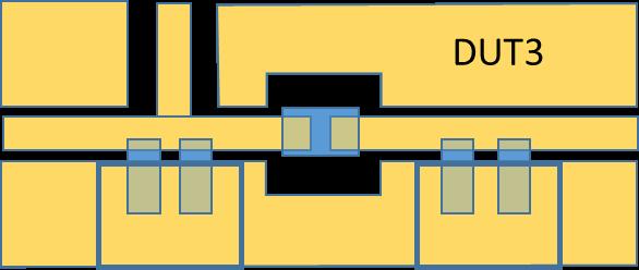
67 Test Board Construction, Build January 29-31,

68 DUT Circuit C1, C2: 47uF 4V 0805 X5R MLCC L1: MHz A 50mOhm January 29-31,
69 Simulation Setup January 29-31,
70 Simulated Corners Voltage transfer function Bias: 0V 0A 4V 0A 0V 1A 4V 1A Input impedance Simulated with LTSPICE and Murata dynamic models. January 29-31,

71 Simulated Voltage Bias Effect Vbias=4 Vbias=0 Simulated with LTSPICE and Murata dynamic models. Idc = 0A Vbias = 0 4V January 29-31,

72 Simulated Current Bias Effect Idc=0 Idc=1 Simulated with LTSPICE and Murata dynamic models. Idc = 0 1A Vbias =4V January 29-31,
73 Measurement Setup Frequency Response Analyzer OUT CH1 CH2 Filter DUT January 29-31,
74 Options for Adding Bias Frequency Response Analyzer Voltage bias from source OUT CH1 CH2 Filter DUT External voltage bias source Electronic load January 29-31,
 2) 3) 1) 2) 3) 1) Omicron")
 5)")
 January 29-31, 2019 75")
75 Bode 100 Setup 1) 4) 3) 5) 1) 2) 3) 1) 2) 3) 1) Omicron Bode 100 2) Laptop 3) DUT 4) DC voltage bias (battery) 5) DC current bias (electronic load) January 29-31,


76 Bode 100 Results 40 Voltage transfer function magnitude [db] V, 0A 4V, 0A 4V, 1A E+2 1.E+3 1.E+4 1.E+5 1.E+6 1.E+7 Frequency [Hz] No-bias V-bias V-A-bias January 29-31,


77 E5061B Gain-Phase Setup January 29-31,
78 E5061B Gain-Phase Results 0V 4V 0V 4V 0V 4V 0V 4V E5061B 0dBm source 0 and 4V DC bias 0A current bias January 29-31,
79 E5061B Gain-Phase Results 0V 10V 0V 10V 0V 10V 0V 10V E5061B 0dBm source 0 and 10V DC bias 0A current bias January 29-31,
80 E5061B Gain-Phase Results 0V 4V 0V 4V 0V 4V 0V 4V E5061B 10dBm source 0 and 4V DC bias 0A current bias January 29-31,

81 E5061B Gain-Phase Results 0V 10V 0V 10V 0V 10V 0V 10V E5061B 10dBm source 0 and 10V DC bias 0A current bias January 29-31,


82 E5061B S-parameter Setup January 29-31,

83 E5061B S-parameter Results E5061B 0dBm source No bias January 29-31,
84 Correlation with No Bias Voltage transfer function magnitude [db] E+2 1.E+3 1.E+4 1.E+5 1.E+6 1.E+7 Frequency [Hz] LTSPICE Bode100 E5061B 0dBm source LTSPICE Bode100 E5061B GP side January 29-31,
85 Correlation with Voltage Bias Voltage transfer function magnitude [db] E+2 1.E+3 1.E+4 1.E+5 1.E+6 1.E+7 Frequency [Hz] LTSPICE Bode100 E5061B 0dBm source LTSPICE Bode100 E5061B GP side January 29-31,
86 Correlation with Voltage and Current Bias 10 Voltage transfer function magnitude at 4V 1A bias [db] dBm source LTSPICE Bode100 E5061B GP side E+2 1.E+3 1.E+4 1.E+5 1.E+6 1.E+7 Frequency [Hz] LTSPICE Bode100 E5061B January 29-31,
87 Acknowledgement and Resources Special thanks to Keysight and Picotest for providing demo equipment Murata for assisting with dynamic models and samples Simulations were done with Analog Devices free LTSPICE Filter evaluation boards This presentation is based on the following training course materials January 29-31,
88 THANK YOU! Any Questions? January 29-31,
How the Braid Impedance of Instrumentation Cables Impact PI and SI Measurements
 How the Braid Impedance of Instrumentation Cables Impact PI and SI Measurements Istvan Novak (*), Jim Nadolny (*), Gary Biddle (*), Ethan Koether (**), Brandon Wong (*) (*) Samtec, (**) Oracle This session
Understanding, measuring, and reducing output noise in DC/DC switching regulators
 Understanding, measuring, and reducing output noise in DC/DC switching regulators Practical tips for output noise reduction Katelyn Wiggenhorn, Applications Engineer, Buck Switching Regulators Robert Blattner,
<Insert Picture Here> DC and AC Bias Dependence of Capacitors
 DC and AC Bias Dependence of Capacitors Istvan Novak, Kendrick Barry Williams, Jason R. Miller, Gustavo Blando, Nathaniel Shannon DesignCon East 211 DCE2, September 27, 211 Outline
Do not measure PDN noise across capacitors!
 PCB Design 007 QuietPower column Do not measure PDN noise across capacitors! Istvan Novak, Oracle, January 2013 Some application notes will tell you that to measure the output ripple of a DC-DC converter,
DesignCon Effect of Power Plane Inductance on Power Delivery Networks. Shirin Farrahi, Cadence Design Systems
 DesignCon 2019 Effect of Power Plane Inductance on Power Delivery Networks Shirin Farrahi, Cadence Design Systems shirinf@cadence.com, 978-262-6008 Ethan Koether, Oracle Corp ethan.koether@oracle.com Mehdi
DesignCon Panel discussion: What is New in DC-DC Converters? V. Joseph Thottuvelil GE Energy Chris Young Intersil Zilker Labs
 DesignCon 2012 Panel discussion: What is New in DC-DC Converters? Panelists: V. Joseph Thottuvelil GE Energy Chris Young Intersil Zilker Labs Steve Weir IPBLOX Istvan Novak* Oracle * panel organizer and
Preamplifier Options for Reducing Cable-Braid Loop Error
 QuietPower columns, December 2018 Preamplifier Options for Reducing Cable-Braid Loop Error Istvan Novak, Samtec It has been known for quite some time [1] that when we measure low impedance with the Two-port
DesignCon East DC and AC Bias Dependence of Capacitors Including Temperature Dependence
 DesignCon East 211 DC and AC Bias Dependence of Capacitors Including Temperature Dependence Istvan Novak, Oracle-America Inc. istvan.novak@oracle.com Kendrick Barry Williams, Oracle-America Inc. kendrick.barry.williams@oracle.com
Core Technology Group Application Note 6 AN-6
 Characterization of an RLC Low pass Filter John F. Iannuzzi Introduction Inductor-capacitor low pass filters are utilized in systems such as audio amplifiers, speaker crossover circuits and switching power
Electrical and Thermal Consequences of Non-Flat Impedance Profiles
 DesignCon 2016 Electrical and Thermal Consequences of Non-Flat Impedance Profiles Jae Young Choi, Oracle Jae.young.choi@oracle.com Ethan Koether, Oracle Ethan.koether@oracle.com Istvan Novak, Oracle Istvan.novak@oracle.com
Frequency-Domain Characterization of Power Distribution Networks
 Frequency-Domain Characterization of Power Distribution Networks Istvan Novak Jason R. Miller ARTECH H O U S E BOSTON LONDON artechhouse.com Preface Acknowledgments xi xv CHAPTER 1 Introduction 1 1.1 Evolution
Non-linear Control for very fast dynamics:
 (CEI) cei@upm.es Non-linear Control for very fast dynamics: Tolerance Analysis and System Limitations Universidad Politécnica de Madrid Madrid DC-DC converter for very fast dynamics Current steps 5 V VRM
Decoupling capacitor uses and selection
 Decoupling capacitor uses and selection Proper Decoupling Poor Decoupling Introduction Covered in this topic: 3 different uses of decoupling capacitors Why we need decoupling capacitors Power supply rail
VCO Design Project ECE218B Winter 2011
 VCO Design Project ECE218B Winter 2011 Report due 2/18/2011 VCO DESIGN GOALS. Design, build, and test a voltage-controlled oscillator (VCO). 1. Design VCO for highest center frequency (< 400 MHz). 2. At
PDN Probes. P2100A/P2101A Data Sheet. 1-Port and 2-Port 50 ohm Passive Probes
 P2100A/P2101A Data Sheet PDN Probes 1-Port and 2-Port 50 ohm Passive Probes power integrity PDN impedance testing ripple PCB resonances transient step load stability and NISM noise TDT/TDR clock jitter
Part I: Dynamic Characterization of DC-DC Converters from a System's Perspective
 DesignCon 212 TecForum 11-MP2: Dynamic Characterization of DC-DC Converters Part I: Dynamic Characterization of DC-DC Converters from a System's Perspective Istvan Novak, Oracle-America Inc. istvan.novak@oracle.com
Controlling Input Ripple and Noise in Buck Converters
 Controlling Input Ripple and Noise in Buck Converters Using Basic Filtering Techniques, Designers Can Attenuate These Characteristics and Maximize Performance By Charles Coles, Advanced Analogic Technologies,
Impact of the Output Capacitor Selection on Switching DCDC Noise Performance
 Impact of the Output Capacitor Selection on Switching DCDC Noise Performance I. Introduction Most peripheries in portable electronics today tend to systematically employ high efficiency Switched Mode Power
Systematic Estimation of Worst-Case PDN Noise Target Impedance and Rogue Waves
 PCB Design 007 QuietPower columns Systematic Estimation of Worst-Case PDN Noise Target Impedance and Rogue Waves Istvan Novak, Oracle, November 2015 In the dark ages of power distribution design, the typical
LDO Regulator Stability Using Ceramic Output Capacitors
 LDO Regulator Stability Using Ceramic Output Capacitors Introduction Ultra-low ESR capacitors such as ceramics are highly desirable because they can support fast-changing load transients and also bypass
Chapter 2. The Fundamentals of Electronics: A Review
 Chapter 2 The Fundamentals of Electronics: A Review Topics Covered 2-1: Gain, Attenuation, and Decibels 2-2: Tuned Circuits 2-3: Filters 2-4: Fourier Theory 2-1: Gain, Attenuation, and Decibels Most circuits
Deconstructing the Step Load Response Reveals a Wealth of Information
 Reveals a Wealth of Information Paul Ho, Senior Engineering Specialist, AEi Systems Steven M. Sandler, Chief Engineer, AEi Systems Charles E. Hymowitz, Managing Director, AEi Systems When analyzing power
1.5MHz, 800mA Synchronous Step-Down Regulator
 1.5MHz, 800mA Synchronous Step-Down Regulator General Description The is a high efficiency current mode synchronous buck PWM DC-DC regulator. The internal generated 0.6V precision feedback reference voltage
Evaluation Board for ADP2118 EVAL-ADP2118
 Evaluation Board for ADP8 EVAL-ADP8 GENERAL DESCRIPTION The evaluation (demo) board provides an easy way to evaluate the ADP8 buck regulator. This data sheet describes how to quickly set up the board to
PL2733A PULAN TECHNOLOGY CO., LIMITED. to 30V. regulator from. and line regulation. programmable synchronous. current limit and.
 Wide Range Synchronous Buck Controller Features Wide Input Voltage Range: 8V to 30V Up to 93% Efficiency Programmable Switching Frequency up to up to 500kHz No Loop Compensation Required Programmable current
Migrating 4195A to E5061B LF-RF Network Analyzer. April 2010 Agilent Technologies
 Migrating 4195A to E61B LF-RF Network Analyzer April 2010 Agilent Technologies Page 1 Contents Overview of 4195A to E61B migration Migrating 4195A to E61B in network measurements Migrating 4195A to E61B
BA Features. General Description. Applications. Marking Information. 3W Mono Filterless Class D Audio Power Amplifier
 3W Mono Filterless Class D Audio Power Amplifier General Description The BA16853 is a cost-effective mono Class D audio power amplifier that assembles in Dual Flat No-Lead Plastic Package (DFN-8). Only
AltiumLive 2017: Component selection for EMC
 AltiumLive 2017: Component selection for EMC Martin O Hara Victory Lighting Ltd Munich, 24-25 October 2017 Component Selection Passives resistors, capacitors and inductors Discrete diodes, bipolar transistors,
Keysight E5061B-3L3/3L4/3L5 LF-RF Network Analyzer with Option 005 Impedance Analysis Function
 Ihr Spezialist für Mess- und Prüfgeräte Keysight E506B-3L3/3L4/3L5 LF-RF Network Analyzer with Option 005 Impedance Analysis Function Data Sheet datatec Ferdinand-Lassalle-Str. 52 72770 Reutlingen Tel.
EUA W Mono Filterless Class-D Audio Power Amplifier DESCRIPTION FEATURES APPLICATIONS. Typical Application Circuit
 3-W Mono Filterless Class-D Audio Power Amplifier DESCRIPTION The EUA2011 is a high efficiency, 3W mono class-d audio power amplifier. A low noise, filterless PWM architecture eliminates the output filter,
What is New about Thin Laminates in 2013?
 PCBDesign 007 QuietPower column What is New about Thin Laminates in 2013? Istvan Novak, Oracle, February 2013 It is almost two years ago that the QuietPower column Thin Laminates: Buried Capacitance or
Outcomes: Core Competencies for ECE145A/218A
 Outcomes: Core Competencies for ECE145A/18A 1. Transmission Lines and Lumped Components 1. Use S parameters and the Smith Chart for design of lumped element and distributed L matching networks. Able to
Design of the Power Delivery System for Next Generation Gigahertz Packages
 Design of the Power Delivery System for Next Generation Gigahertz Packages Madhavan Swaminathan Professor School of Electrical and Computer Engg. Packaging Research Center madhavan.swaminathan@ece.gatech.edu
SN W Mono Filterless Class-D Audio Power Amplifier DESCRIPTION FEATURES APPLICATIONS. Typical Application Circuit
 2.6W Mono Filterless Class-D Audio Power Amplifier DESCRIPTION The SN200 is a 2.6W high efficiency filter-free class-d audio power amplifier in a.5 mm.5 mm wafer chip scale package (WCSP) that requires
Testing Power Sources for Stability
 Keywords Venable, frequency response analyzer, oscillator, power source, stability testing, feedback loop, error amplifier compensation, impedance, output voltage, transfer function, gain crossover, bode
Decoupling capacitor placement
 Decoupling capacitor placement Covered in this topic: Introduction Which locations need decoupling caps? IC decoupling Capacitor lumped model How to maximize the effectiveness of a decoupling cap Parallel
Designing a Multi-Phase Asynchronous Buck Regulator Using the LM2639
 Designing a Multi-Phase Asynchronous Buck Regulator Using the LM2639 Overview The LM2639 provides a unique solution to high current, low voltage DC/DC power supplies such as those for fast microprocessors.
Filterless 3W Class- D Mono Audio Amplifier
 Preliminary Datasheet LPA00 Filterless 3W Class- D Mono Audio Amplifier General Description The LPA00 is a 3W, class-d audio amplifier. It offers low THD+N, allowing it to achieve high-quality Power Supply
4.5V to 32V Input High Current LED Driver IC For Buck or Buck-Boost Topology CN5816. Features: SHDN COMP OVP CSP CSN
 4.5V to 32V Input High Current LED Driver IC For Buck or Buck-Boost Topology CN5816 General Description: The CN5816 is a current mode fixed-frequency PWM controller for high current LED applications. The
Homework Assignment 05
 Homework Assignment 05 Question (2 points each unless otherwise indicated)(20 points). Estimate the parallel parasitic capacitance of a mh inductor with an SRF of 220 khz. Answer: (2π)(220 0 3 ) = ( 0
50 ma, High Voltage, Micropower Linear Regulator ADP1720
 5 ma, High Voltage, Micropower Linear Regulator ADP72 FEATURES Wide input voltage range: 4 V to 28 V Maximum output current: 5 ma Low light load current: 28 μa at μa load 35 μa at μa load Low shutdown
ELC224 Final Review (12/10/2009) Name:
 Name:") ELC224 Final Review (12/10/2009) Name: Select the correct answer to the problems 1 through 20. 1. A common-emitter amplifier that uses direct coupling is an example of a dc amplifier. 2. The frequency
ELC224 Final Review (12/10/2009) Name: Select the correct answer to the problems 1 through 20. 1. A common-emitter amplifier that uses direct coupling is an example of a dc amplifier. 2. The frequency
Understanding and Optimizing Electromagnetic Compatibility in Switchmode Power Supplies
 Understanding and Optimizing Electromagnetic Compatibility in Switchmode Power Supplies 1 Definitions EMI = Electro Magnetic Interference EMC = Electro Magnetic Compatibility (No EMI) Three Components
SUN MHz, 800mA Synchronous Step-Down Converter GENERAL DESCRIPTION EVALUATION BOARD APPLICATIONS. Typical Application
 GENERAL DESCRIPTION The is a 1.5MHz constant frequency, slope compensated current mode PWM stepdown converter. The device integrates a main switch and a synchronous rectifier for high efficiency without
Dual, Current Feedback Low Power Op Amp AD812
 a FEATURES Two Video Amplifiers in One -Lead SOIC Package Optimized for Driving Cables in Video Systems Excellent Video Specifications (R L = ): Gain Flatness. db to MHz.% Differential Gain Error. Differential
Yet More On Decoupling, Part 2: ring the changes, change the rings Kendall Castor-Perry
 Page 1 of 9 Yet More On Decoupling, Part 2: ring the changes, change the rings Kendall Castor-Perry This article was published on EDN: http://www.edn.com/design/powermanagement/4412870/why-bypass-caps-make-a-difference---part-2--power-supplyexcitation-and-ringing
WD3122EC. Descriptions. Features. Applications. Order information. High Efficiency, 28 LEDS White LED Driver. Product specification
 High Efficiency, 28 LEDS White LED Driver Descriptions The is a constant current, high efficiency LED driver. Internal MOSFET can drive up to 10 white LEDs in series and 3S9P LEDs with minimum 1.1A current
EUA2011A. Low EMI, Ultra-Low Distortion, 2.5-W Mono Filterless Class-D Audio Power Amplifier DESCRIPTION FEATURES APPLICATIONS
 Low EMI, Ultra-Low Distortion, 2.5-W Mono Filterless Class-D Audio Power Amplifier DESCRIPTION The EUA2011A is a high efficiency, 2.5W mono class-d audio power amplifier. A new developed filterless PWM
10 Mb/s Single Twisted Pair Ethernet PHY Coupling Network Steffen Graber Pepperl+Fuchs
 10 Mb/s Single Twisted Pair Ethernet PHY Coupling Network Steffen Graber Pepperl+Fuchs IEEE P802.3cg 10 Mb/s Single Twisted Pair Ethernet Task Force 6/21/2017 1 Overview Coupling Network Coupling Network
Application Note 323. Flex Power Modules. Input Filter Design - 3E POL Regulators
 Application Note 323 Flex Power Modules Input Filter Design - 3E POL Regulators Introduction The design of the input capacitor is critical for proper operation of the 3E POL regulators and also to minimize
The Quantitative Measurement of the Effectiveness of Decoupling Capacitors in Controlling Switching Transients from Microprocessors
 The Quantitative Measurement of the Effectiveness of Decoupling Capacitors in Controlling Switching Transients from Microprocessors Dale L. Sanders X2Y Attenuators, LLC 37554 Hills Tech Dr. Farmington
6.334 Final Project Buck Converter
 Nathan Monroe monroe@mit.edu 4/6/13 6.334 Final Project Buck Converter Design Input Filter Filter Capacitor - 40µF x 0µF Capstick CS6 film capacitors in parallel Filter Inductor - 10.08µH RM10/I-3F3-A630
PART MAX2605EUT-T MAX2606EUT-T MAX2607EUT-T MAX2608EUT-T MAX2609EUT-T TOP VIEW IND GND. Maxim Integrated Products 1
 19-1673; Rev 0a; 4/02 EVALUATION KIT MANUAL AVAILABLE 45MHz to 650MHz, Integrated IF General Description The are compact, high-performance intermediate-frequency (IF) voltage-controlled oscillators (VCOs)
AN726. Vishay Siliconix AN726 Design High Frequency, Higher Power Converters With Si9166
 AN726 Design High Frequency, Higher Power Converters With Si9166 by Kin Shum INTRODUCTION The Si9166 is a controller IC designed for dc-to-dc conversion applications with 2.7- to 6- input voltage. Like
Power Supply Rejection Ratio Measurement
 Power Supply Rejection Ratio Measurement Using the Bode 100 and the Picotest J2120A Line Injector By Florian Hämmerle & Steve Sandler 2010 Picotest.com Visit www.picotest.com for more information. Contact
1.5 MHz, 600mA Synchronous Step-Down Converter
 GENERAL DESCRIPTION is a 1.5Mhz constant frequency, slope compensated current mode PWM step-down converter. The device integrates a main switch and a synchronous rectifier for high efficiency without an
LR8509 Series 1.5MHz 600mA Synchronous Step-Down Converter
 LR8509 Series 1.5MHz 600mA Synchronous Step-Down Converter INTRODUCTION: The LR8509 is a 1.5MHz constant frequency, slope compensated current mode PWM synchronous step-down converter. High switching frequency
MT3420 Rev.V1.2 GENERAL DESCRIPTION FEATURES APPLICATIONS. 1.4MHz, 2A Synchronous Step-Down Converter
 1.4MHz, 2A Synchronous Step-Down Converter FEATURES High Efficiency: Up to 96% 1.4MHz Constant Frequency Operation 2A Output Current No Schottky Diode Required 2.5V to 5.5V Input Voltage Range Output Voltage
Theory: The idea of this oscillator comes from the idea of positive feedback, which is described by Figure 6.1. Figure 6.1: Positive Feedback
 Name1 Name2 12/2/10 ESE 319 Lab 6: Colpitts Oscillator Introduction: This lab introduced the concept of feedback in combination with bipolar junction transistors. The goal of this lab was to first create
Passive Components around ADAS Applications By Ron Demcko, AVX Fellow, AVX Corporation
 Passive Components around ADAS Applications By Ron Demcko, AVX Fellow, AVX Corporation The importance of high reliability - high performance electronics is accelerating as Advanced Driver Assistance Systems
150 ma, Low Dropout, CMOS Linear Regulator ADP1710/ADP1711
 5 ma, Low Dropout, CMOS Linear Regulator ADP7/ADP7 FEATURES Maximum output current: 5 ma Input voltage range: 2.5 V to 5.5 V Light load efficient IGND = 35 μa with zero load IGND = 4 μa with μa load Low
Practical Limitations of State of the Art Passive Printed Circuit Board Power Delivery Networks for High Performance Compute Systems
 Practical Limitations of State of the Art Passive Printed Circuit Board Power Delivery Networks for High Performance Compute Systems Presented by Chad Smutzer Mayo Clinic Special Purpose Processor Development
QPI-AN1 GENERAL APPLICATION NOTE QPI FAMILY BUS SUPPLY QPI CONVERTER
 QPI-AN1 GENERAL APPLICATION NOTE QPI FAMILY EMI control is a complex design task that is highly dependent on many design elements. Like passive filters, active filters for conducted noise require careful
DIO6605B 5V Output, High-Efficiency 1.2MHz, Synchronous Step-Up Converter
 5V Output, High-Efficiency 1.2MHz, Synchronous Step-Up Converter Rev 0.2 Features High-Efficiency Synchronous-Mode 2.7-4.5V input voltage range Device Quiescent Current: 30µA(TYP) Less than 1µA Shutdown
1.5MHz, 2A Synchronous Step-Down Regulator
 1.5MHz, 2A Synchronous Step-Down Regulator General Description The is a high efficiency current mode synchronous buck PWM DC-DC regulator. The internal generated 0.6V precision feedback reference voltage
Experiment 1: Instrument Familiarization (8/28/06)
") Electrical Measurement Issues Experiment 1: Instrument Familiarization (8/28/06) Electrical measurements are only as meaningful as the quality of the measurement techniques and the instrumentation applied
Electrical Measurement Issues Experiment 1: Instrument Familiarization (8/28/06) Electrical measurements are only as meaningful as the quality of the measurement techniques and the instrumentation applied
Advanced Topics in EMC Design. Issue 1: The ground plane to split or not to split?
 NEEDS 2006 workshop Advanced Topics in EMC Design Tim Williams Elmac Services C o n s u l t a n c y a n d t r a i n i n g i n e l e c t r o m a g n e t i c c o m p a t i b i l i t y e-mail timw@elmac.co.uk
How to Measure LDO PSRR
 How to Measure LDO PSRR Measure LDO PSRR with Network Analyzer Power supply rejection ratio (PSRR) or some time called power supply ripple rejection measurements are often difficult to measure, especially
Power Distribution Network Design for Stratix IV GX and Arria II GX FPGAs
 Power Distribution Network Design for Stratix IV GX and Arria II GX FPGAs Transceiver Portfolio Workshops 2009 Question What is Your PDN Design Methodology? Easy Complex Historical Full SPICE simulation
TS mA / 1.5MHz Synchronous Buck Converter
 SOT-25 Pin Definition: 1. EN 2. Ground 3. Switching Output 4. Input 5. Feedback General Description The TS3406 is a high efficiency monolithic synchronous buck regulator using a 1.5MHz constant frequency,
The Inductance Loop Power Distribution in the Semiconductor Test Interface. Jason Mroczkowski Multitest
 The Inductance Loop Power Distribution in the Semiconductor Test Interface Jason Mroczkowski Multitest j.mroczkowski@multitest.com Silicon Valley Test Conference 2010 1 Agenda Introduction to Power Delivery
DIO6305 High-Efficiency 1.2MHz, 1.1A Synchronous Step-Up Converter
 High-Efficiency 1.2MHz, 1.1A Synchronous Step-Up Converter Rev 1.2 Features High-Efficiency Synchronous-Mode 2.7-5.25V input voltage range Device Quiescent Current: 30µA (TYP) Less than 1µA Shutdown Current
Custom Interconnects Fuzz Button with Hardhat Test Socket/Interposer 1.00 mm pitch
 Custom Interconnects Fuzz Button with Hardhat Test Socket/Interposer 1.00 mm pitch Measurement and Model Results prepared by Gert Hohenwarter 12/14/2015 1 Table of Contents TABLE OF CONTENTS...2 OBJECTIVE...
350 ma, Low VIN, Low Quiescent Current, CMOS Linear Regulator ADP130
 35 ma, Low VIN, Low Quiescent Current, CMOS Linear Regulator ADP3 FEATURES 35 ma maximum output current Input voltage supply range VBIAS = 2.3 V to 5.5 V VIN =.2 V to 3.6 V 2.3 V < VIN < 3.6 V, VIN can
Picotest s Power Integrity Workshop
 Picotest s Power Integrity Workshop Course Overview In this workshop, taught by leading author ( Power Integrity -- Measuring, Optimizing and Troubleshooting Power Systems ) and Test Engineer of the Year
EMC output filter recommendations for MA120XX(P)
") EMC output filter recommendations for MA120XX(P) About this document Scope and purpose This document provides EMC output filter recommendations that are tailored to the Merus Audio s MA12040, MA12040P,
EMC output filter recommendations for MA120XX(P) About this document Scope and purpose This document provides EMC output filter recommendations that are tailored to the Merus Audio s MA12040, MA12040P,
Datasheet. 5A 240KHZ 36V PWM Buck DC/DC Converter. Features
 General Description The is a 240 KHz fixed frequency monolithic step down switch mode regulator with a built in internal Power MOSFET. It achieves 5A continuous output current over a wide input supply
200 ma Output Current High-Speed Amplifier AD8010
 a FEATURES 2 ma of Output Current 9 Load SFDR 54 dbc @ MHz Differential Gain Error.4%, f = 4.43 MHz Differential Phase Error.6, f = 4.43 MHz Maintains Video Specifications Driving Eight Parallel 75 Loads.2%
1.9GHz Power Amplifier
 EVALUATION KIT AVAILABLE MAX2248 General Description The MAX2248 single-supply, low-voltage power amplifier (PA) IC is designed specifically for applications in the 188MHz to 193MHz frequency band. The
Making Invasive and Non-Invasive Stability Measurements
 Making Invasive and Non-Invasive s Using the Bode 1 and the PICOTEST J2111A Current Injector By Florian Hämmerle & Steve Sandler 21 Picotest.com Visit www.picotest.com for more information. Contact support@picotest.com
HX1151 GENERAL DESCRIPTION FEATURES APPLICATIONS TYPICAL APPLICATION. Step-Down Converter. 1.5MHz, 1.3A Synchronous
 1.5MHz, 1.3A Synchronous Step-Down Converter FEATURES High Efficiency: Up to 96% 1.5MHz Constant Frequency Operation 1300mA Output Current No Schottky Diode Required 2.3 to 6 Input oltage Range Adjustable
Evaluation Board for Filterless Class-D Audio Amplifier EVAL-SSM2335
 Evaluation Board for Filterless Class-D Audio Amplifier EVAL-SSM2335 FEATURES Single-ended and differential input capability User-friendly interface connection Optimized EMI suppression filter assembled
Background (What Do Line and Load Transients Tell Us about a Power Supply?)
") Maxim > Design Support > Technical Documents > Application Notes > Power-Supply Circuits > APP 3443 Keywords: line transient, load transient, time domain, frequency domain APPLICATION NOTE 3443 Line and
Maxim > Design Support > Technical Documents > Application Notes > Power-Supply Circuits > APP 3443 Keywords: line transient, load transient, time domain, frequency domain APPLICATION NOTE 3443 Line and
Differential-Mode Emissions
 Differential-Mode Emissions In Fig. 13-5, the primary purpose of the capacitor C F, however, is to filter the full-wave rectified ac line voltage. The filter capacitor is therefore a large-value, high-voltage
PCB Design Guidelines for GPS chipset designs. Section 1. Section 2. Section 3. Section 4. Section 5
 PCB Design Guidelines for GPS chipset designs The main sections of this white paper are laid out follows: Section 1 Introduction Section 2 RF Design Issues Section 3 Sirf Receiver layout guidelines Section
A DESIGN EXPERIMENT FOR MEASUREMENT OF THE SPECTRAL CONTENT OF SUBSTRATE NOISE IN MIXED-SIGNAL INTEGRATED CIRCUITS
 A DESIGN EXPERIMENT FOR MEASUREMENT OF THE SPECTRAL CONTENT OF SUBSTRATE NOISE IN MIXED-SIGNAL INTEGRATED CIRCUITS Marc van Heijningen, John Compiet, Piet Wambacq, Stéphane Donnay and Ivo Bolsens IMEC
2A 150KHZ PWM Buck DC/DC Converter. Features
 General Description The is a of easy to use adjustable step-down (buck) switch-mode voltage regulator. The device is available in an adjustable output version. It is capable of driving a 2A load with excellent
New and Upcoming Power Related. Challenges. Instructor: Steve Sandler Better Products Through Better Test
 New and Upcoming Power Related Challenges Instructor: Steve Sandler Steve@Picotest.com Better Products Through Better Test And Just a Bit About Steve 40+ Years Experience (1977-present) AEi Systems Founder
Designing Microphone Preamplifiers. Steve Green 24th AES UK Conference June 2011
 Designing Microphone Preamplifiers Steve Green 24th AES UK Conference June 2011 This presentation is an abbreviated version of a tutorial given at the 2010 AES Conference in San Francisco. The complete
Rail-to-Rail, High Output Current Amplifier AD8397
 Rail-to-Rail, High Output Current Amplifier FEATURES Dual operational amplifier Voltage feedback Wide supply range from 3 V to 24 V Rail-to-rail output Output swing to within.5 V of supply rails High linear
MIC2245. Features. General Description. Applications. Typical Application. 4MHz PWM Synchronous Buck Regulator with LDO Standby Mode
 4MHz PWM Synchronous Buck Regulator with LDO Standby Mode General Description The Micrel is a high efficiency 4MHz pulse width modulated (PWM) synchronous buck (stepdown) regulator that features a LOWQ
AT7450 2A-60V LED Step-Down Converter
 FEATURES DESCRIPTION IN Max = 60 FB = 200m Frequency 52kHz I LED Max 2A On/Off input may be used for the Analog Dimming Thermal protection Cycle-by-cycle current limit I LOAD max =2A OUT from 0.2 to 55
1.0MHz,24V/2.0A High Performance, Boost Converter
 1.0MHz,24V/2.0A High Performance, Boost Converter General Description The LP6320C is a 1MHz PWM boost switching regulator designed for constant-voltage boost applications. The can drive a string of up
APPLICATION NOTE 6071 CHOOSE THE RIGHT REGULATOR FOR THE RIGHT JOB: PART 3, COMPONENT SELECTION
 Keywords: Switching Regulators,Step Down,Inductors,Simulation,EE-Sim,component selection APPLICATION NOTE 6071 CHOOSE THE RIGHT REGULATOR FOR THE RIGHT JOB: PART 3, COMPONENT SELECTION By: Don Corey, Principal
Filters And Waveform Shaping
 Physics 3330 Experiment #3 Fall 2001 Purpose Filters And Waveform Shaping The aim of this experiment is to study the frequency filtering properties of passive (R, C, and L) circuits for sine waves, and
WD3119 WD3119. High Efficiency, 40V Step-Up White LED Driver. Descriptions. Features. Applications. Order information 3119 FCYW 3119 YYWW
 High Efficiency, 40V Step-Up White LED Driver Http//:www.sh-willsemi.com Descriptions The is a constant current, high efficiency LED driver. Internal MOSFET can drive up to 10 white LEDs in series and
AS SERIES (2.00 x 1.6 Package) Up to 20 Watt DC-DC Converter
 Up to 20 Watt DC-DC Converter") PRODUCT OVERVIEW The AS series offer up to 20 watts of output power in standard 2.00 x 1.60 x 0.45 inches packages. This series features high efficiency and 1500 Volts of DC isolation. The AS series provides
PRODUCT OVERVIEW The AS series offer up to 20 watts of output power in standard 2.00 x 1.60 x 0.45 inches packages. This series features high efficiency and 1500 Volts of DC isolation. The AS series provides
Built-In OVP White LED Step-up Converter in Tiny Package
 Built-In White LED Step-up Converter in Tiny Package Description The is a step-up DC/DC converter specifically designed to drive white LEDs with a constant current. The device can drive up to 4 LEDs in
Evaluation Board Analog Output Functions and Characteristics
 Evaluation Board Analog Output Functions and Characteristics Application Note July 2002 AN1023 Introduction The ISL5239 Evaluation Board includes the circuit provisions to convert the baseband digital
Datasheet. 4A 240KHZ 23V PWM Buck DC/DC Converter. Features
 General Description Features The is a 240 KHz fixed frequency monolithic step down switch mode regulator with a built in internal Power MOSFET. It achieves 4A continuous output current over a wide input