Power Supply Rejection Ratio Measurement
|
|
|
- Karen Thomas
- 5 years ago
- Views:
Transcription


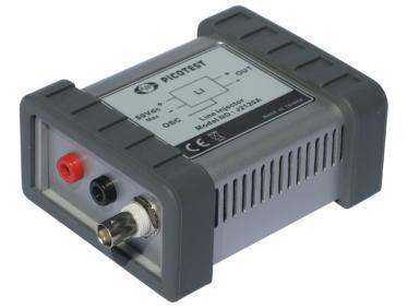
1 Page 1 of 9 Measurement Using the Bode 100 and the J2120A Line Injector Voltage Regulator Contact us: sales@telesplicing.com.tw
2 Page 2 of 9 Table of Contents 1 Executive Summary Measurement Task Measurement Setup & Results Measurement Setup Device Setup Calibration Measurement Conclusion...9 Note: Basic procedures such as setting-up, adjusting and calibrating the Bode 100 are described in the Bode 100 user manual. The J2120A Line Injector does not require calibration.
3 Page 3 of 9 1 Executive Summary This application note shows how the, or PSRR of a linear voltage regulator (LM317) can be measured using the Bode 100 and additional accessories. The same techniques can be used to measure switching regulators as well. The measurements are performed on the Voltage Regulator Test Standard (VRTS) testing board 1 using the J2120A Line Injector.

4 2 Measurement Task Bode Application Note The PSRR of the LM317 linear voltage regulator is measured with the Bode 100 and the J2120A line injector. A capacitor is then connected to the output of the regulator and the PSRR is again measured from 10 Hz to 10 MHz. The VRTS kit is used as the basis for the testing. The VRTS can be used to help perform most of the common voltage regulator measurements using the Bode 100 in conjunction with the Signal Injectors. The VRTS kit includes the regulators and capacitors used for the measurements in this application note. Page 4 of 9 Voltage Regulator Test Standard board, Source (1)

5 Page 5 of 9 3 Measurement Setup & Results The PSRR describes how a signal on the DC input voltage of the regulator system is transmitted to the regulated output. The PSRR is generally measured in db and defined to be: Where and are the AC ripple of the input and output voltage, respectively. PSRR Voltage Regulator GND Depending on the definition the PSRR can be a negative or positive number. Using the above definition, the PSRR generally is a negative number. 3.1 Measurement Setup The PSRR can be measured by applying a sinusoidal ripple on the supply voltage and measuring the gain from input to output of the regulator. The J2120A Line Injector allows you to add the sinusoidal output voltage of the Bode 100 to the DC-supply voltage of the regulator. The PSRR is then measured by connecting two voltage probes to the input and output of the regulator. In this case two 1:1 voltage probes are used. The following figure shows the principle measurement setup: PSRR measurement setup, Source (1)

6 Note: The output impedance of the J2120A is slightly resistive. An input capacitor on the regulator would, therefore, create a low pass network and change the PSRR results. The measurements shown in this application note are performed without an input capacitor! The J2111A Current Injector acts as a load for the voltage regulator. The +bias of the J2111A is switched on resulting in a constant current load of 25 ma. The voltage probes and injectors are connected to the Bode 100 and the VRTS board as shown in the following picture: Page 6 of 9 PSRR example measurement setup


7 Page 7 of Device Setup The PSRR measurement can be performed directly with the Bode 100 using the external reference. The Bode 100 is set up as follows: Measurement Mode: Frequency Sweep Mode Start Frequency: 10 Hz Stop Frequency: 10 MHz Sweep Mode: Logarithmic Number of Points: 401 or more Receiver Bandwidth: 100 Hz Attenuator 1 &2: 10 db Level: -10 dbm Note: When the Bode 100 is used with the J2120A the output level should be set in the range from -20 to 10 dbm. The PSRR measurement is a small signal measurement and so the goal is only to maintain a level above the noise floor. Note: Use of the full speed mode is not recommended for measurements with the J2120A. To switch on the external reference start the device configuration window and click on the external reference switch symbol: Both channels are set to high input impedance. Trace 1 measurement is set to gain and the format to Mag(dB).

8 Page 8 of Calibration If two dissimilar probes are used for the measurements a thru calibration has to be performed before the measurement is carried out. During the thru calibration both probes have to be connected to the input point as shown on the following picture: Probe connection during thru calibration 3.4 Measurement You can get started using the settings and setup from above the measurement. Performing a single sweep leads to the following PSRR curve: 0 TR1/dB TR1: Mag(Gain) f/hz At low frequencies the PSRR is very high which results in high suppression of disturbances from the supply line. In the higher frequency area of > 1 MHz the PSRR gets very small and even reaches 0 db at 6 MHz. This means that a 6 MHz signal would pass through the regulator without attenuation.
9 To see the influence of an output capacitor on the PSRR the VRTS capacitor No.2 is connected to the regulator output. This 0.1 µf ceramic capacitor changes the PSRR curve as follows: Page 9 of 9 0 TR1/dB TR1: Mag(Gain) The PSRR does not drop below an attenuation of about 10 db. 4 Conclusion f/hz The Bode 100 in combination with the J2120A Line Injector offers a test set that enables simple and fast PSRR measurements in a wide frequency range starting at 10 Hz and reaching 10 MHz. No injection transformer is necessary for the test set. This setup allows you to measure the PSRR even in systems with high DC currents up to 5 A without the danger of destroying an expensive transformer. Contact us: sales@telesplicing.com.tw
Power Supply Rejection Ratio Measurement
 Power Supply Rejection Ratio Measurement Using the Bode 100 and the Picotest J2120A Line Injector By Florian Hämmerle & Steve Sandler 2010 Picotest.com Visit www.picotest.com for more information. Contact
Power Supply Rejection Ratio Measurement
 Power Supply Rejection Ratio Measurement Using the Bode 100 and the Picotest J2120A Line Injector www.telesplicing.com.tw +886-2-27053146 sales@telesplicing.com.tw Page 2 of 10 Table of Contents 1 EXECUTIVE
Power Supply Rejection Ratio Measurement
 Power Supply Rejection Ratio Measurement Using the Bode 100 and the Picotest J2120A Line Injector By Florian Hämmerle & Steve Sandler 2017 by OMICRON Lab V2.0 Visit www.omicron-lab.com for more information.
Battery Impedance Measurement
 Page 1 of 8 Using the Bode 100 and the Picotest J2111A Current Injector Page 2 of 8 Table of Contents 1 Executive Summary...3 2 Measurement Task...3 3 Measurement Setup & Results...4 3.1.1 Device Setup...5
Invasive and Non-Invasive Stability Measurements
 Bode 1 - Application Note Page 1 of 22 Invasive and Non-Invasive Stability Measurements Using the Bode 1 and the Picotest J2111A Current Injector By Florian Hämmerle & Steve Sandler 211 Omicron Lab V1.1
Making Invasive and Non-Invasive Stability Measurements
 Making Invasive and Non-Invasive s Using the Bode 1 and the PICOTEST J2111A Current Injector By Florian Hämmerle & Steve Sandler 21 Picotest.com Visit www.picotest.com for more information. Contact support@picotest.com
S-Parameter Measurements with the Bode 100
 Page 1 of 10 with the Bode 100 Page 2 of 10 Table of Contents 1 S-Parameters...3 2 S-Parameter Measurement with the Bode 100...4 2.1 Device Setup...4 2.2 Calibration...5 2.3 Measurement...7 2.3.1 S11 and
DC/DC Converter Stability Measurement
 Bode 1 - Application Note Page 1 of 15 DC/DC Converter Stability Measurement Strongly supported by By Stephan Synkule, Lukas Heinzle & Florian Hämmerle 213 Omicron Lab V2. Visit www.omicron-lab.com for
DC Biased Impedance Measurement
 DC Biased Impedance Measurement Using the Bode 100 and the Picotest J2130A DC Bias Injector By Florian Hämmerle & Steve Sandler 2011 Picotest.com Visit www.picotest.com for more information. Contact support@picotest.com
Solar Cell Impedance Measurement using the Bode 100
 Page 1 of 9 Measurement using the Bode 100 By Florian Hämmerle 2011 Omicron Lab V1.0 Visit www.omicron-lab.com for more information. Contact support@omicron-lab.com for technical support. Page 2 of 9 Table
Equivalent Circuit Determination of Quartz Crystals
 Page 1 of 11 Equivalent Circuit Determination of Quartz Crystals By Stephan Synkule & Florian Hämmerle 2010 Omicron Lab V1.1 Visit www.omicron-lab.com for more information. Contact support@omicron-lab.com
DC/DC Converter Stability Measurement
 Strongly supported by By Stephan Synkule, Lukas Heinzle & Florian Hämmerle 214 by OMICRON Lab V2.1 Visit www.omicron-lab.com for more information. Contact support@omicron-lab.com for technical support.
Measuring Impedance with the Bode 100. OMICRON Lab Webinar Nov. 2014
 Measuring Impedance with the Bode 100 OMICRON Lab Webinar Nov. 2014 Let s start with a question Why do the presenters wear moustaches? http://moteam.co/omimobros Page 4 Agenda Direct Impedance measurement
Documentation. Voltage Regulator Test Standard. Test Platform for Voltage Regulator and LDO Testing
 Voltage Regulator Test Standard Test Platform for Voltage Regulator and LDO Testing Documentation Version 1.0d, December, 2010 2010 Picotest Corp. All Rights Reserved. Trademarks The Picotest logo and
Passive Component Analysis. OMICRON Lab Webinar Nov. 2015
 Passive Component Analysis OMICRON Lab Webinar Nov. 2015 Webinar Hints Activate the chat function Please mute your microphones to avoid echoes Feel free to post questions anytime using the chat function
Low Value Impedance Measurement using the Voltage / Current Method
 Low Value Impedance Measurement using the Voltage / Current Method By Florian Hämmerle & Tobias Schuster 2017 Omicron Lab V2.2 Visit www.omicron-lab.com for more information. Contact support@omicron-lab.com
Measuring Power Line Impedance
 By Florian Hämmerle & Tobias Schuster 2017 by OMICRON Lab V1.1 Visit www.omicron-lab.com for more information. Contact support@omicron-lab.com for technical support. Page 2 of 13 Table of Contents 1 MEASUREMENT
Exclusive Technology Feature. An Accurate Method For Measuring Capacitor ESL. ISSUE: April by Steve Sandler, Picotest, Phoenix, Ariz.
 ISSUE: April 2011 An Accurate Method For Measuring Capacitor ESL by Steve Sandler, Picotest, Phoenix, Ariz. The equivalent series inductance (ESL) of chip capacitors is becoming an increasingly important
Signal Injectors. Documentation. Version 1.00, October, Picotest Corp. All Rights Reserved.
 Signal Injectors Documentation Version 1.00, October, 2010 2010 Picotest Corp. All Rights Reserved. Trademarks The Picotest logo and Picotest Injectors are trademarks of Picotest Corp. All other brand
Measure Low Value Impedance Current Shunt Impedance
 Measure Low Value Impedance Current Shunt Impedance By Florian Hämmerle 2017 Omicron Lab V2.0 Visit www.omicron-lab.com for more information. Contact support@omicron-lab.com for technical support. Page
Non Invasive Assessment of Voltage Regulator Phase Margin without Access to the Control Loop
 Non Invasive Assessment of Voltage Regulator Phase Margin without Access to the Control Loop By Steven Sandler and Charles Hymowitz, Picotest.com Many voltage regulators are of the fixed output variety
DC/DC Converter Stability Measurement
 Strongly supported by By Stephan Synkule, Lukas Heinzle & Florian Hämmerle 2018 by OMICRON Lab V3.3 Visit www.omicron-lab.com for more information. Contact support@omicron-lab.com for technical support.
Opamp stability using non-invasive methods
 Opamp stability using non-invasive methods Opamps are frequently use in instrumentation systems as unity gain analog buffers, voltage reference buffers and ADC input buffers as well as low gain preamplifiers.
How to Measure LDO PSRR
 How to Measure LDO PSRR Measure LDO PSRR with Network Analyzer Power supply rejection ratio (PSRR) or some time called power supply ripple rejection measurements are often difficult to measure, especially
Documentation. Voltage Regulator Test Standard. Test Platform for Voltage Regulator and LDO Testing
 Voltage Regulator Test Standard Test Platform for Voltage Regulator and LDO Testing Documentation Version 1.0a, January, 2012 Copyright 2011 2012 Picotest Corp. All Rights Reserved Trademarks The Picotest
Measurement of the equivalent circuit of quartz crystals
 Measurement of the equivalent circuit of quartz crystals This application note shows how to measure the equivalent circuit of a quartz crystal with Bode 100. A.) Basics: An equivalent describtion of a
Quick Site Testing with the 8800SX
 Quick Site Testing with the 8800SX Site Testing with the 8800SX Basic Tests 5 site testing involves several tests to verify site operation. NOTE: This is not intended to be a complete commissioning procedure.
ECE3204 D2015 Lab 1. See suggested breadboard configuration on following page!
 ECE3204 D2015 Lab 1 The Operational Amplifier: Inverting and Non-inverting Gain Configurations Gain-Bandwidth Product Relationship Frequency Response Limitation Transfer Function Measurement DC Errors
Equivalent Circuit Determination of Quartz Crystals
 Equivalent Circuit Determination of Quartz Crystals By Stephan Synkule & Florian Hämmerle 2017 by OMICRON Lab V2.1 Visit www.omicron-lab.com for more information. Contact support@omicron-lab.com for technical
Positive-Voltage Regulators. Nominal output voltage
 Rev.1. Jan. 2010. Positive-Voltage Regulators 3-Terminal Regulators Output Current Up to 100mA No External Components Internal Thermal Overload Protection Internal Short-Circuit Limiting Direct Replacement
Audio Amplifier Frequency Response
 By Tobias Schuster 2017 by OMICRON Lab V2.0 Visit www.omicron-lab.com for more information. Contact support@omicron-lab.com for technical support. Page 2 of 20 Table of Contents 1 EXECUTIVE SUMMARY...
Measuring LDOs requires more bandwidth than you think
 Measuring LDOs requires more bandwidth than you think by Bernhard Baumgartner, OMICRON Lab, and Steve Sandler and Charles Hymowitz, AEi Systems, Los Angeles, Calif. Most electronic systems contain at least
Demo / Application Guide for DSA815(-TG) / DSA1000 Series
 / DSA1000 Series") Demo / Application Guide for DSA815(-TG) / DSA1000 Series TX1000 Mobile Phone Frontend Mixer Bandpass Filter PA The schematic above shows a typical front end of a mobile phone. Our TX1000 RF Demo Kit shows
Demo / Application Guide for DSA815(-TG) / DSA1000 Series TX1000 Mobile Phone Frontend Mixer Bandpass Filter PA The schematic above shows a typical front end of a mobile phone. Our TX1000 RF Demo Kit shows
When you have completed this exercise, you will be able to determine the frequency response of an
 RC Coupling When you have completed this exercise, you will be able to determine the frequency response of an oscilloscope. The way in which the gain varies with frequency is called the frequency response.
Filterless 3W Class- D Mono Audio Amplifier
 Preliminary Datasheet LPA00 Filterless 3W Class- D Mono Audio Amplifier General Description The LPA00 is a 3W, class-d audio amplifier. It offers low THD+N, allowing it to achieve high-quality Power Supply
Background (What Do Line and Load Transients Tell Us about a Power Supply?)
") Maxim > Design Support > Technical Documents > Application Notes > Power-Supply Circuits > APP 3443 Keywords: line transient, load transient, time domain, frequency domain APPLICATION NOTE 3443 Line and
Maxim > Design Support > Technical Documents > Application Notes > Power-Supply Circuits > APP 3443 Keywords: line transient, load transient, time domain, frequency domain APPLICATION NOTE 3443 Line and
Input Impedance Measurements for Stable Input-Filter Design
 for Stable Input-Filter Design 1000 Converter Input Impedance 100 10 1 0,1 Filter Output Impedance 0,01 10 100 1000 10000 100000 By Florian Hämmerle 2017 by OMICRON Lab V1.0 Visit www.omicron-lab.com for
EXTEND YOUR REACH. Copper Mountain Technologies USB VNAs. S-parameter measurement solutions from 9 khz to 110 GHz Measured parameters from S 11
 Copper Mountain Technologies USB VNAs S-parameter measurement solutions from 9 khz to 110 GHz Measured parameters from S 11 to S 44 Dynamic range as high as 162 db typ. (1 Hz IF bandwidth) Measurement
DC Biased Impedance Measurements MOSFET
 DC Biased Impedance Measurements MOSFET By Florian Hämmerle, Steve Sandler & Tobias Schuster 2017 by OMICRON Lab V2.0 Visit www.omicron-lab.com for more information. Contact support@omicron-lab.com for
Smart Measurement Solutions. Bode 100. User Manual
 Smart Measurement Solutions Bode 100 User Manual Bode 100 User Manual Bode 100 User Manual Article Number VESD0661 - Manual Version: Bode100.AE.4 OMICRON Lab 2010. All rights reserved. This User Manual
MEASURING HUM MODULATION USING MATRIX MODEL HD-500 HUM DEMODULATOR
 MEASURING HUM MODULATION USING MATRIX MODEL HD-500 HUM DEMODULATOR The SCTE defines hum modulation as, The amplitude distortion of a signal caused by the modulation of the signal by components of the power
A Walk Through the MSA Software Vector Network Analyzer Transmission Mode 12/18/09
 A Walk Through the MSA Software Vector Network Analyzer Transmission Mode 12/18/09 This document is intended to familiarize you with the basic features of the MSA and its software, operating as a Vector
Lab 9 Frequency Domain
 Lab 9 Frequency Domain 1 Components Required Resistors Capacitors Function Generator Multimeter Oscilloscope 2 Filter Design Filters are electric components that allow applying different operations to
Test No. 1. Introduction to Scope Measurements. Report History. University of Applied Sciences Hamburg. Last chance!! EEL2 No 1
 University of Applied Sciences Hamburg Group No : DEPARTMENT OF INFORMATION ENGINEERING Laboratory for Instrumentation and Measurement L: in charge of the report Test No. Date: Assistant A2: Professor:
DEPARTMENT OF INFORMATION ENGINEERING. Test No. 1. Introduction to Scope Measurements. 1. Correction. Term Correction. Term...
 2. Correction. Correction Report University of Applied Sciences Hamburg Group No : DEPARTMENT OF INFORMATION ENGINEERING Laboratory for Instrumentation and Measurement L: in charge of the report Test No.
Vector Network Analyzers (VERY) Basics. Tom Powers USPAS SRF Testing Course 19 Jan. 2014
 Basics. Tom Powers USPAS SRF Testing Course 19 Jan. 2014") Vector Network Analyzers (VERY) Basics Tom Powers USPAS SRF Testing Course 19 Jan. 2014 S-Parameters A scattering matrix relates the voltage waves incident on the ports of a network to those reflected
Vector Network Analyzers (VERY) Basics Tom Powers USPAS SRF Testing Course 19 Jan. 2014 S-Parameters A scattering matrix relates the voltage waves incident on the ports of a network to those reflected
VVM measurement with E5061B for replacing 8508A vector voltmeter. May 2013 Agilent Technologies
 VVM measurement with E5061B for replacing 8508A vector voltmeter May 2013 Agilent Technologies Overview of VVM measurement with E5061B Application discussed here Measuring the phase difference (& magnitude
ALX-SSB 5 Band Filter Assembly Manual 19 November 2018
 ALX-SSB 5 Band Filter Assembly Manual 19 November 2018 Contents Theory of Operation:... 1 Figure 1... 2 Parts Included:... 4 Board Overview:... 5 Figure 2... 5 Figure 3... 5 Board Assembly:... 6 Cable
Keysight E5061B ENA Vector Network Analyzer CONFIGURATION GUIDE
 Keysight E5061B ENA Vector Network Analyzer CONFIGURATION GUIDE Ordering guide The following steps will guide you through configuring your E5061B. Standard furnished item 1 Installation guide CD ROM IO
PDN Probes. P2100A/P2101A Data Sheet. 1-Port and 2-Port 50 ohm Passive Probes
 P2100A/P2101A Data Sheet PDN Probes 1-Port and 2-Port 50 ohm Passive Probes power integrity PDN impedance testing ripple PCB resonances transient step load stability and NISM noise TDT/TDR clock jitter
Positive-Voltage Regulators
 SPECIFICATION VSP MIKRON Positive-Voltage Regulators Серия КБ5006ЕНХX-4/MB 3-Terminal Regulators Output Current Up to 100mA No External Components Internal Thermal Overload Protection Internal Short-Circuit
Experiment 8 Frequency Response
 Experiment 8 Frequency Response W.T. Yeung, R.A. Cortina, and R.T. Howe UC Berkeley EE 105 Spring 2005 1.0 Objective This lab will introduce the student to frequency response of circuits. The student will
ML12561 Crystal Oscillator
 ML56 Crystal Oscillator Legacy Device: Motorola MC56 The ML56 is the military temperature version of the commercial ML06 device. It is for use with an external crystal to form a crystal controlled oscillator.
Gain Lab. Image interference during downconversion. Images in Downconversion. Course ECE 684: Microwave Metrology. Lecture Gain and TRL labs
 Gain Lab Department of Electrical and Computer Engineering University of Massachusetts, Amherst Course ECE 684: Microwave Metrology Lecture Gain and TRL labs In lab we will be constructing a downconverter.
Bode 100. User Manual
 Bode 100 User Manual Bode 100 User Manual Article Number VESD0661 - Manual Version: Bode100.AE.3 OMICRON Lab 2008. All rights reserved. This User Manual is a publication of OMICRON electronics GmbH. This
LM4808 Dual 105 mw Headphone Amplifier
 Dual 105 mw Headphone Amplifier General Description The is a dual audio power amplifier capable of delivering 105 mw per channel of continuous average power into a16ωload with 0.1% (THD+N) from a 5V power
Methods for Reducing Emissions from Switching Power Circuits. A. McDowell, C. Zhu and T. Hubing
 Methods for Reducing Emissions from Switching Power Circuits A. McDowell, C. Zhu and T. Hubing 1 Objective To reduce radiated emissions and other forms of interference from power inverter circuits, by
R. W. Erickson. Department of Electrical, Computer, and Energy Engineering University of Colorado, Boulder
 R. W. Erickson Department of Electrical, Computer, and Energy Engineering University of Colorado, Boulder Graphical construction of transfer functions 8.3. Graphical construction of impedances and transfer
78xx. Positive-Voltage Regulator. Pin Description V IN V OUT C IN C OUT OUT GND IN OUT GND IN
 Positive-oltage Regulator Description The 78xx series are fixed-voltage monolithic integrated circuit voltage regulators designed for wide range of applications. Each of these regulators can deliver up
87415A microwave system amplifier A microwave. system amplifier A microwave system amplifier A microwave.
 20 Amplifiers 83020A microwave 875A microwave 8308A microwave 8307A microwave 83006A microwave 8705C preamplifier 8705B preamplifier 83050/5A microwave The Agilent 83006/07/08/020/050/05A test s offer
500mA CMOS Ultra Low Dropout Linear Regulator
 500mA CMOS Ultra Low Dropout Linear Regulator Description The series are 500mA CMOS ultra low dropout positive voltage regulators which operate from 2.4V to 5.5V input supply. The ultra low dropout linear
Product Overview: Main Features: AV3672A/B/C -S Vector Network Analyzer. (10MHz~13.5 GHz/26.5 GHz/43.5 GHz)
") AV3672A/B/C -S Vector Network Analyzer (10MHz~13.5 GHz/26.5 GHz/43.5 GHz) Product Overview: AV3672*-S series vector network analyzer is consist of AV3672A-S(10MHz~13.5GHz), AV3672B-S(10MHz~26.5GHz)and
AV3672A/B/C -S Vector Network Analyzer (10MHz~13.5 GHz/26.5 GHz/43.5 GHz) Product Overview: AV3672*-S series vector network analyzer is consist of AV3672A-S(10MHz~13.5GHz), AV3672B-S(10MHz~26.5GHz)and
EUA2011A. Low EMI, Ultra-Low Distortion, 2.5-W Mono Filterless Class-D Audio Power Amplifier DESCRIPTION FEATURES APPLICATIONS
 Low EMI, Ultra-Low Distortion, 2.5-W Mono Filterless Class-D Audio Power Amplifier DESCRIPTION The EUA2011A is a high efficiency, 2.5W mono class-d audio power amplifier. A new developed filterless PWM
140mW Headphone Amplifier with Unity-gain Stable
 140mW Headphone Amplifier with Unity-gain Stable General Description The LPA4809 is a dual audio power amplifier capable of delivering 140mW per channel of continuous average power into a 16Ω load with
Lab 9: Operational amplifiers II (version 1.5)
") Lab 9: Operational amplifiers II (version 1.5) WARNING: Use electrical test equipment with care! Always double-check connections before applying power. Look for short circuits, which can quickly destroy
Lab 9: Operational amplifiers II (version 1.5) WARNING: Use electrical test equipment with care! Always double-check connections before applying power. Look for short circuits, which can quickly destroy
Radio ETI031 Laboratory Experiments 2: VECTOR NETWORK ANALYSER, ANTENNA and RECEIVER MEASUREMENTS
 Lund University Electrical and Information Technology GJ 2007-09-30 Radio ETI031 Laboratory Experiments 2: VECTOR NETWORK ANALYSER, ANTENNA and RECEIVER MEASUREMENTS Göran Jönsson 2007 Objectives: Part
AV3672 Series Vector Network Analyzer
 AV3672 Series Vector Network Analyzer AV3672A/B/C/D/E (10MHz 13.5 GHz/26.5 GHz/43.5 GHz/50 GHz/67 GHz) Product Overview: AV3672 series vector network analyzer include AV3672A (10MHz 13.5GHz), AV3672B (10MHz
SN W Mono Filterless Class-D Audio Power Amplifier DESCRIPTION FEATURES APPLICATIONS. Typical Application Circuit
 2.6W Mono Filterless Class-D Audio Power Amplifier DESCRIPTION The SN200 is a 2.6W high efficiency filter-free class-d audio power amplifier in a.5 mm.5 mm wafer chip scale package (WCSP) that requires
Filters And Waveform Shaping
 Physics 3330 Experiment #3 Fall 2001 Purpose Filters And Waveform Shaping The aim of this experiment is to study the frequency filtering properties of passive (R, C, and L) circuits for sine waves, and
Simulating Circuits James Lamberti 5/4/2014
 Simulating Circuits James Lamberti (jal416@lehigh.edu) 5/4/2014 There are many simulation and design platforms for circuits. The two big ones are Altium and Cadence. This tutorial will focus on Altium,
EUA6210 Output Capacitor-less 67mW Stereo Headphone Amplifier
 Output Capacitor-less 67mW Stereo Headphone Amplifier DESCRIPTION The is an audio power amplifier primarily designed for headphone applications in portable device applications. It is capable of delivering
Specification for Conducted Emission Test
 1 of 10 1. EMI Receiver Frequency range 9kHz 7.0 GHz Measurement time per frequency 10 µs to 100 s time sweep, span = 0 Hz - 1 µs to 16000 s Sweep time in steps of 5 % frequency sweep, span 10 Hz - 2.5
DATASHEET EL2072. Features. Applications. Pinout. Ordering Information. 730MHz Closed Loop Buffer
 730MHz Closed Loop Buffer OBSOLETE PRODUCT NO RECOMMENDED REPLACEMENT contact our Technical Support Center at 1-888-INTERSIL or www.intersil.com/tsc DATASHEET FN7033 Rev 0.00 The EL2072 is a wide bandwidth,
RF Characterization Report
 SMA-J-P-H-ST-MT1 Mated with: RF316-01SP1-01BJ1-0305 Description: 50-Ω SMA Board Mount Jack, Mixed Technology Samtec, Inc. 2005 All Rights Reserved Table of Contents Introduction...1 Product Description...1
Methods for Testing Impulse Noise Tolerance
 Methods for Testing Impulse Noise Tolerance May,6,2015 Larry Cohen Overview Purpose: Describe some potential test methods for impulse noise tolerance What we will cover in this presentation: Discuss need
Contactless RFID Tag Measurements
 By Florian Hämmerle & Martin Bitschnau 2017 by OMICRON Lab V3.1 Visit www.omicron-lab.com for more information. Contact support@omicron-lab.com for technical support. Page 2 of 13 Table of Contents 1 Executive
Hot S 22 and Hot K-factor Measurements
 Application Note Hot S 22 and Hot K-factor Measurements Scorpion db S Parameter Smith Chart.5 2 1 Normal S 22.2 Normal S 22 5 0 Hot S 22 Hot S 22 -.2-5 875 MHz 975 MHz -.5-2 To Receiver -.1 DUT Main Drive
Lab 4: Analysis of the Stereo Amplifier
 ECE 212 Spring 2010 Circuit Analysis II Names: Lab 4: Analysis of the Stereo Amplifier Objectives In this lab exercise you will use the power supply to power the stereo amplifier built in the previous
LM V, Mono 85mW BTL Output, 14mW Stereo Headphone Audio Amplifier
 1.5V, Mono 85mW BTL Output, 14mW Stereo Headphone Audio Amplifier General Description The unity gain stable LM4919 is both a mono-btl audio power amplifier and a Single Ended (SE) stereo headphone amplifier.
Virtual Lab 1: Introduction to Instrumentation
 Virtual Lab 1: Introduction to Instrumentation By: Steve Badelt and Daniel D. Stancil Department of Electrical and Computer Engineering Carnegie Mellon University Pittsburgh, PA Purpose: Measurements and
S3602A/B Vector Network Analyzer Datasheet
 S3602A/B Vector Network Analyzer Datasheet Saluki Technology Inc. The document applies to the vector network analyzers of the following models: S3602A vector network analyzer (10MHz-13.5GHz). S3602B vector
SIMULATION OF A SERIES RESONANT CIRCUIT ECE562: Power Electronics I COLORADO STATE UNIVERSITY. Modified in Fall 2011
 SIMULATION OF A SERIES RESONANT CIRCUIT ECE562: Power Electronics I COLORADO STATE UNIVERSITY Modified in Fall 2011 ECE 562 Series Resonant Circuit (NL5 Simulation) Page 1 PURPOSE: The purpose of this
Low voltage LNA, mixer and VCO 1GHz
 DESCRIPTION The is a combined RF amplifier, VCO with tracking bandpass filter and mixer designed for high-performance low-power communication systems from 800-1200MHz. The low-noise preamplifier has a
EUA W Mono Filterless Class-D Audio Power Amplifier DESCRIPTION FEATURES APPLICATIONS. Typical Application Circuit
 3-W Mono Filterless Class-D Audio Power Amplifier DESCRIPTION The EUA2011 is a high efficiency, 3W mono class-d audio power amplifier. A low noise, filterless PWM architecture eliminates the output filter,
Circuit Characterization with the Agilent 8714 VNA
 Circuit Characterization with the Agilent 8714 VNA By: Larry Dunleavy Wireless and Microwave Instruments University of South Florida Objectives 1) To examine the concepts of reflection, phase shift, attenuation,
ELC224 Final Review (12/10/2009) Name:
 Name:") ELC224 Final Review (12/10/2009) Name: Select the correct answer to the problems 1 through 20. 1. A common-emitter amplifier that uses direct coupling is an example of a dc amplifier. 2. The frequency
ELC224 Final Review (12/10/2009) Name: Select the correct answer to the problems 1 through 20. 1. A common-emitter amplifier that uses direct coupling is an example of a dc amplifier. 2. The frequency
1GHz low voltage LNA, mixer and VCO
 DESCRIPTION The is a combined RF amplifier, VCO with tracking bandpass filter and mixer designed for high-performance low-power communication systems from 800-1200MHz. The low-noise preamplifier has a
MIC General Description. Features. Applications. Typical Application. 1.5A Low Voltage LDO Regulator w/dual Input Voltages
 MIC4915 1.5A Low oltage LDO Regulator w/dual Input oltages General Description The MIC4915 is a high-bandwidth, low-dropout, 1.5A voltage regulator ideal for powering core voltages of lowpower microprocessors.
Test No. 2. Advanced Scope Measurements. History. University of Applied Sciences Hamburg. Last chance!! EEL2 No 2
 University of Applied Sciences Hamburg Group No : DEPARTMENT OF INFORMATION ENGINEERING Laboratory for Instrumentation and Measurement L1: in charge of the report Test No. 2 Date: Assistant A2: Professor:
Agilent AN Applying Error Correction to Network Analyzer Measurements
 Agilent AN 287-3 Applying Error Correction to Network Analyzer Measurements Application Note 2 3 4 4 5 6 7 8 0 2 2 3 3 4 Table of Contents Introduction Sources and Types of Errors Types of Error Correction
Testing Power Sources for Stability
 Keywords Venable, frequency response analyzer, oscillator, power source, stability testing, feedback loop, error amplifier compensation, impedance, output voltage, transfer function, gain crossover, bode
S Powered by +5V Supply. S Input Configurable for Electrical and Optical Evaluation
 19-4980; Rev 0; 9/09 MAX3806 Evaluation Kit General Description The MAX3806 evaluation kit (EV kit) is an assembled and tested demonstration board that simplifies evaluation of the MAX3806 receiver for
Keysight E5061B-3L3/3L4/3L5 LF-RF Network Analyzer with Option 005 Impedance Analysis Function
 Ihr Spezialist für Mess- und Prüfgeräte Keysight E506B-3L3/3L4/3L5 LF-RF Network Analyzer with Option 005 Impedance Analysis Function Data Sheet datatec Ferdinand-Lassalle-Str. 52 72770 Reutlingen Tel.
Option 010 adds the impedance measurement function to the 4396B. By installing this option
 Product Overview Option 010 adds the impedance measurement function to the 4396B. By installing this option into the 4396B spectrum/network/impedance analyzer, you can measure impedance parameters directly.
Transformer modelling
 By Martin Bitschnau 2017 by OMICRON Lab V2.0 Visit www.omicron-lab.com for more information. Contact support@omicron-lab.com for technical support. Page 2 of 21 Table of Contents 1 EXECUTIVE SUMMARY...
Picotest s Power Integrity Workshop
 Picotest s Power Integrity Workshop Course Overview In this workshop, taught by leading author ( Power Integrity -- Measuring, Optimizing and Troubleshooting Power Systems ) and Test Engineer of the Year
3.2 Measuring Frequency Response Of Low-Pass Filter :
 2.5 Filter Band-Width : In ideal Band-Pass Filters, the band-width is the frequency range in Hz where the magnitude response is at is maximum (or the attenuation is at its minimum) and constant and equal
SAMPLE: EXPERIMENT 2 Series RLC Circuit / Bode Plot
 SAMPLE: EXPERIMENT 2 Series RLC Circuit / Bode Plot ---------------------------------------------------------------------------------------------------- This experiment is an excerpt from: Electric Experiments
Keywords: ISM, RF, transmitter, short-range, RFIC, switching power amplifier, ETSI
 Maxim > Design Support > Technical Documents > Application Notes > Wireless and RF > APP 4929 Keywords: ISM, RF, transmitter, short-range, RFIC, switching power amplifier, ETSI APPLICATION NOTE 4929 Adapting
250 MHz, Voltage Output 4-Quadrant Multiplier AD835
 a FEATURES Simple: Basic Function is W = XY + Z Complete: Minimal External Components Required Very Fast: Settles to.% of FS in ns DC-Coupled Voltage Output Simplifies Use High Differential Input Impedance