S-Parameter Measurements with the Bode 100
|
|
|
- Willis Warren
- 5 years ago
- Views:
Transcription


1 Page 1 of 10 with the Bode 100
2 Page 2 of 10 Table of Contents 1 S-Parameters S-Parameter Measurement with the Bode Device Setup Calibration Measurement S11 and S S22 and S Appendix...9

, resistance parameters (z), with a mixture of both (h-parameters) or using s-parameters.")
3 Page 3 of 10 1 S-Parameters S-Parameters (scattering parameters) have been introduced to describe linear networks at high frequencies. S-parameters can be used to fully describe linear multi-port networks and are supported by many simulation tools. In the following the parameters are explained on a 2-port network. The figure below shows a 2-port network with port 1 on the left side and port 2 on the right side. Such a network can be described using conductance parameters (y), resistance parameters (z), with a mixture of both (h-parameters) or using s-parameters. S-parameters describe the network in terms of travelling waves. An incoming wave reaching a two port network is partially reflected at the input port, resulting in and partially transmitted to the output port, resulting in. The following figure illustrates the incoming and outgoing waves at the two port network. The S-parameters describe the relation between the reflected and transmitted waves. The elements of the scattering matrix are called s-parameters. The parameters and have the meaning of reflection coefficients, the parameters and the meaning of transmission coefficients. A big advantage of the s-parameters is that all the measurements to determine the parameters can be done in a system with defined reference impedance (e.g. ). This enables the use of matched cables without influencing the measurement.


4 2 S-Parameter Measurement with the Bode Device Setup Bode Information The Bode 100 supports the measurement of s-parameters. For the s-parameter measurement, it is important that the channel 2 input impedance is set to and the channel 1 is set to internal reference. These settings can be applied in the device configuration window. Page 4 of 10 Note: CH1 reference and input impedance can be toggled by clicking on the switch symbols. To display of in trace 1 and in trace 2 the following trace settings have to be set: Note: Gain Reflection (Details on this can be found in the Appendix)


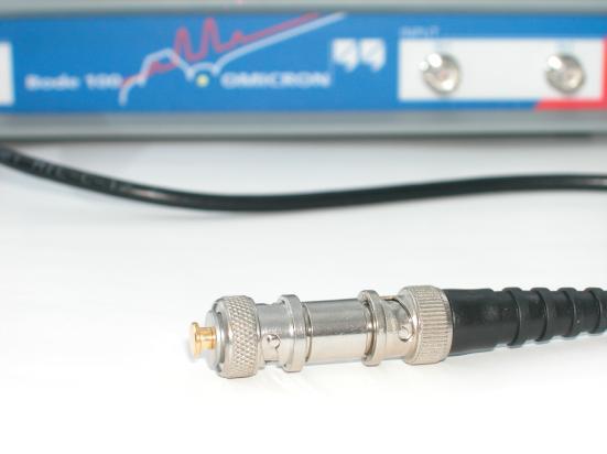
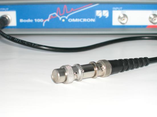
5 Page 5 of Calibration It is recommended to perform a probe calibration before performing the measurement. To calibrate the measurement a thru calibration has to be performed. To do so, connect the output of the Bode 100 with CH2 using connection cables and a thru connector as shown in the pictures below. Now the calibration can be started. After the calibration process is finished the indicator field turns from red to green color.

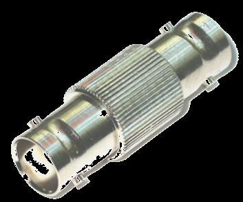
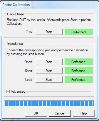
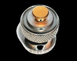
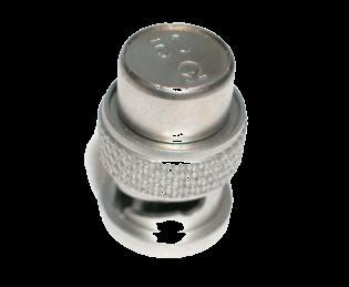

6 To calibrate the measurement a reflection/impedance calibration has to be performed. To do so, connect the open, short and load standards as shown in the pictures below. OPEN: Page 6 of 10 SHORT: LOAD: After performing the calibrations the calibration icons turn blue. This indicates that the calibrations are active:

 f/hz TR2: Mag(Reflection) Trace 1")
7 Page 7 of Measurement S11 and S21 To measure the device under test (DUT), connect it as shown in the figure below. The Bode 100 output is connected to port 1 of the DUT and port 2 of the DUT is connected to the Bode 100 channel 2. Coaxial cable Performing a measurement leads to a result as shown in the example figure below. 0 5 TR1/dB TR2/dB *10 5 4*10 5 6*10 5 8* TR1: Mag(Gain) f/hz TR2: Mag(Reflection) Trace 1 is the transmission coefficient in db ( ), trace 2 shows the reflection coefficient in db ( ).

8 Page 8 of S22 and S12 To measure the reverse transmission and reflection coefficients and the same setup and calibration can be used simply the DUT has to be reversed. To measure and port 1 of the DUT is connected to the Bode 100 output: To measure and port 2 of the DUT is connected to the Bode 100 output:
9 Page 9 of 10 3 Appendix 1) Reflection Measurement The measurement is performed with matched impedance load and source ( ) such that there is no reflection from the load ( ). In the matched load case from the matrix equation results in: Where and are the wave variables which are defined in terms of voltage and current as follows: Using this relation can be rewritten: Where and therefore The reflection coefficient equals the reflection measurement of the Bode 100.

10 Page 10 of 10 2) Transmission Measurement The measurement is performed with matched impedance load and source ( ) such that there is no reflection from the load ( ). In the matched load case from the matrix equation results in: Where and are the wave variables which are defined in terms of voltage and current as follows: Using this relation can be rewritten Where and and therefore This equals the gain calculated by the Bode 100 using the internal reference.
Power Supply Rejection Ratio Measurement
 Page 1 of 9 Measurement Using the Bode 100 and the J2120A Line Injector Voltage Regulator Contact us: +886-2-27053146 sales@telesplicing.com.tw Page 2 of 9 Table of Contents 1 Executive Summary...3 2 Measurement
Battery Impedance Measurement
 Page 1 of 8 Using the Bode 100 and the Picotest J2111A Current Injector Page 2 of 8 Table of Contents 1 Executive Summary...3 2 Measurement Task...3 3 Measurement Setup & Results...4 3.1.1 Device Setup...5
Equivalent Circuit Determination of Quartz Crystals
 Page 1 of 11 Equivalent Circuit Determination of Quartz Crystals By Stephan Synkule & Florian Hämmerle 2010 Omicron Lab V1.1 Visit www.omicron-lab.com for more information. Contact support@omicron-lab.com
Power Supply Rejection Ratio Measurement
 Power Supply Rejection Ratio Measurement Using the Bode 100 and the Picotest J2120A Line Injector By Florian Hämmerle & Steve Sandler 2010 Picotest.com Visit www.picotest.com for more information. Contact
DC/DC Converter Stability Measurement
 Bode 1 - Application Note Page 1 of 15 DC/DC Converter Stability Measurement Strongly supported by By Stephan Synkule, Lukas Heinzle & Florian Hämmerle 213 Omicron Lab V2. Visit www.omicron-lab.com for
Measuring Impedance with the Bode 100. OMICRON Lab Webinar Nov. 2014
 Measuring Impedance with the Bode 100 OMICRON Lab Webinar Nov. 2014 Let s start with a question Why do the presenters wear moustaches? http://moteam.co/omimobros Page 4 Agenda Direct Impedance measurement
Passive Component Analysis. OMICRON Lab Webinar Nov. 2015
 Passive Component Analysis OMICRON Lab Webinar Nov. 2015 Webinar Hints Activate the chat function Please mute your microphones to avoid echoes Feel free to post questions anytime using the chat function
Making Invasive and Non-Invasive Stability Measurements
 Making Invasive and Non-Invasive s Using the Bode 1 and the PICOTEST J2111A Current Injector By Florian Hämmerle & Steve Sandler 21 Picotest.com Visit www.picotest.com for more information. Contact support@picotest.com
DC/DC Converter Stability Measurement
 Strongly supported by By Stephan Synkule, Lukas Heinzle & Florian Hämmerle 214 by OMICRON Lab V2.1 Visit www.omicron-lab.com for more information. Contact support@omicron-lab.com for technical support.
Invasive and Non-Invasive Stability Measurements
 Bode 1 - Application Note Page 1 of 22 Invasive and Non-Invasive Stability Measurements Using the Bode 1 and the Picotest J2111A Current Injector By Florian Hämmerle & Steve Sandler 211 Omicron Lab V1.1
Solar Cell Impedance Measurement using the Bode 100
 Page 1 of 9 Measurement using the Bode 100 By Florian Hämmerle 2011 Omicron Lab V1.0 Visit www.omicron-lab.com for more information. Contact support@omicron-lab.com for technical support. Page 2 of 9 Table
Exclusive Technology Feature. An Accurate Method For Measuring Capacitor ESL. ISSUE: April by Steve Sandler, Picotest, Phoenix, Ariz.
 ISSUE: April 2011 An Accurate Method For Measuring Capacitor ESL by Steve Sandler, Picotest, Phoenix, Ariz. The equivalent series inductance (ESL) of chip capacitors is becoming an increasingly important
CAL U100B CAL U100B CDN M016 CAL U100B CDN M016 CAL U100B. Used as M2 CDN. Used as M3 CDN
 out < +0 out < +0 ch. < +0 ch. < +0 ch. < +7 ch. < +0 ch. < +0 ch. < +7 LL LL nd nd 0 8... Test setup calibration with a CDN The calibration setup always refers to the type of CDN. The CDN user manuals
Waveguide Calibration with Copper Mountain Technologies VNA
 Clarke & Severn Electronics Ph: +612 9482 1944 BUY NOW www.cseonline.com.au Introduction Waveguide components possess certain advantages over their counterpart devices with co-axial connectors: they can
The Active Bridge 11/20/09
 The Active Bridge 11/20/09 The Active Bridge is an op-amp based reflection bridge that produces an output proportional to the signal reflected by an attached device under test (DUT). It can therefore be
Measuring Power Line Impedance
 By Florian Hämmerle & Tobias Schuster 2017 by OMICRON Lab V1.1 Visit www.omicron-lab.com for more information. Contact support@omicron-lab.com for technical support. Page 2 of 13 Table of Contents 1 MEASUREMENT
Measurement of the equivalent circuit of quartz crystals
 Measurement of the equivalent circuit of quartz crystals This application note shows how to measure the equivalent circuit of a quartz crystal with Bode 100. A.) Basics: An equivalent describtion of a
Low Value Impedance Measurement using the Voltage / Current Method
 Low Value Impedance Measurement using the Voltage / Current Method By Florian Hämmerle & Tobias Schuster 2017 Omicron Lab V2.2 Visit www.omicron-lab.com for more information. Contact support@omicron-lab.com
Power Supply Rejection Ratio Measurement
 Power Supply Rejection Ratio Measurement Using the Bode 100 and the Picotest J2120A Line Injector www.telesplicing.com.tw +886-2-27053146 sales@telesplicing.com.tw Page 2 of 10 Table of Contents 1 EXECUTIVE
Audio Amplifier Frequency Response
 By Tobias Schuster 2017 by OMICRON Lab V2.0 Visit www.omicron-lab.com for more information. Contact support@omicron-lab.com for technical support. Page 2 of 20 Table of Contents 1 EXECUTIVE SUMMARY...
Swept Return Loss & VSWR Antenna Measurements using the Eagle Technologies RF Bridge
 Swept Return Loss & VSWR Antenna Measurements using the Eagle Technologies RF Bridge April, 2015 Page 1 of 7 Introduction Return loss and VSWR are a measure of the magnitude of a transmitted RF Signal
Application Note: Swept Return Loss & VSWR Antenna Measurements using the Eagle Technologies RF Bridge
 : Swept Return Loss & VSWR Antenna Measurements using the Eagle Technologies RF Bridge FCT-1008A Introduction Return loss and VSWR are a measure of the magnitude of a transmitted RF Signal in relation
The 2-Port Shunt-Through Measurement and the Inherent Ground Loop
 The Measurement and the Inherent Ground Loop The 2-port shunt-through measurement is the gold standard for measuring milliohm impedances while supporting measurement at very high frequencies (GHz). These
Measuring PCB, Cable and Interconnect Impedance, Dielectric Constants, Velocity Factor, and Lengths
 Measuring PCB, Cable and Interconnect Impedance, Dielectric Constants, Velocity Factor, and Lengths Controlled impedance printed circuit boards (PCBs) often include a measurement coupon, which typically
Aries Kapton CSP socket
 Aries Kapton CSP socket Measurement and Model Results prepared by Gert Hohenwarter 5/19/04 1 Table of Contents Table of Contents... 2 OBJECTIVE... 3 METHODOLOGY... 3 Test procedures... 4 Setup... 4 MEASUREMENTS...
Keysight MOI for USB Type-C Connectors & Cable Assemblies Compliance Tests (Type-C to Legacy Cable Assemblies)
") Revision 01.01 Jan-21, 2016 Universal Serial Bus Type-C TM Specification Revision 1.1 Keysight Method of Implementation (MOI) for USB Type-C TM Connectors and Cables Assemblies Compliance Tests Using Keysight
Revision 01.01 Jan-21, 2016 Universal Serial Bus Type-C TM Specification Revision 1.1 Keysight Method of Implementation (MOI) for USB Type-C TM Connectors and Cables Assemblies Compliance Tests Using Keysight
Keysight MOI for USB Type-C Connectors & Cable Assemblies Compliance Tests (Type-C to Legacy Cable Assemblies)
") Revision 01.00 Nov-24, 2015 Universal Serial Bus Type-C TM Specification Revision 1.1 Keysight Method of Implementation (MOI) for USB Type-C TM Connectors and Cables Assemblies Compliance Tests Using Keysight
Revision 01.00 Nov-24, 2015 Universal Serial Bus Type-C TM Specification Revision 1.1 Keysight Method of Implementation (MOI) for USB Type-C TM Connectors and Cables Assemblies Compliance Tests Using Keysight
FieldFox Handheld Education Series Part 3: Calibration Techniques for Precise Field Measurements
 FieldFox Handheld Education Series Part 3: Calibration Techniques for Precise Field Measurements FieldFox Handheld Education Series Interference Testing Cable and Antenna Measurements Calibration Techniques
How to Measure LDO PSRR
 How to Measure LDO PSRR Measure LDO PSRR with Network Analyzer Power supply rejection ratio (PSRR) or some time called power supply ripple rejection measurements are often difficult to measure, especially
DC Biased Impedance Measurement
 DC Biased Impedance Measurement Using the Bode 100 and the Picotest J2130A DC Bias Injector By Florian Hämmerle & Steve Sandler 2011 Picotest.com Visit www.picotest.com for more information. Contact support@picotest.com
Network Analysis Basics
 Adolfo Del Solar Application Engineer adolfo_del-solar@agilent.com MD1010 Network B2B Agenda Overview What Measurements do we make? Network Analyzer Hardware Error Models and Calibration Example Measurements
Aries QFP microstrip socket
 Aries QFP microstrip socket Measurement and Model Results prepared by Gert Hohenwarter 2/18/05 1 Table of Contents Table of Contents... 2 OBJECTIVE... 3 METHODOLOGY... 3 Test procedures... 4 Setup... 4
NATIONAL UNIVERSITY of SINGAPORE
 NATIONAL UNIVERSITY of SINGAPORE Faculty of Engineering Electrical & Computer Engineering Department EE3104 Introduction to RF and Microwave Systems & Circuits Experiment 1 Familiarization on VNA Calibration
Quick Site Testing with the 8800SX
 Quick Site Testing with the 8800SX Site Testing with the 8800SX Basic Tests 5 site testing involves several tests to verify site operation. NOTE: This is not intended to be a complete commissioning procedure.
Measurements with Scattering Parameter By Joseph L. Cahak Copyright 2013 Sunshine Design Engineering Services
 Measurements with Scattering Parameter By Joseph L. Cahak Copyright 2013 Sunshine Design Engineering Services Network Analyzer Measurements In many RF and Microwave measurements the S-Parameters are typically
Agilent AN Applying Error Correction to Network Analyzer Measurements
 Agilent AN 287-3 Applying Error Correction to Network Analyzer Measurements Application Note 2 3 4 4 5 6 7 8 0 2 2 3 3 4 Table of Contents Introduction Sources and Types of Errors Types of Error Correction
Vector Network Analyzers (VERY) Basics. Tom Powers USPAS SRF Testing Course 19 Jan. 2014
 Basics. Tom Powers USPAS SRF Testing Course 19 Jan. 2014") Vector Network Analyzers (VERY) Basics Tom Powers USPAS SRF Testing Course 19 Jan. 2014 S-Parameters A scattering matrix relates the voltage waves incident on the ports of a network to those reflected
Vector Network Analyzers (VERY) Basics Tom Powers USPAS SRF Testing Course 19 Jan. 2014 S-Parameters A scattering matrix relates the voltage waves incident on the ports of a network to those reflected
RF Characterization Report
 SMA-J-P-H-ST-MT1 Mated with: RF316-01SP1-01BJ1-0305 Description: 50-Ω SMA Board Mount Jack, Mixed Technology Samtec, Inc. 2005 All Rights Reserved Table of Contents Introduction...1 Product Description...1
Agilent On-wafer Balanced Component Measurement using the ENA RF Network Analyzer with the Cascade Microtech Probing System. Product Note E5070/71-3
 Agilent On-wafer Balanced Component Measurement using the ENA RF Network Analyzer with the Cascade Microtech Probing ystem Product Note E5070/71-3 Introduction The use of differential circuit topologies
EE290C - Spring 2004 Advanced Topics in Circuit Design
 EE290C - Spring 2004 Advanced Topics in Circuit Design Lecture #3 Measurements with VNA and TDR Ben Chia Tu-Th 4 5:30pm 531 Cory Agenda Relationships between time domain and frequency domain TDR Time Domain
VVM measurement with E5061B for replacing 8508A vector voltmeter. May 2013 Agilent Technologies
 VVM measurement with E5061B for replacing 8508A vector voltmeter May 2013 Agilent Technologies Overview of VVM measurement with E5061B Application discussed here Measuring the phase difference (& magnitude
Comparison of Various RF Calibration Techniques in Production: Which is Right for You? Daniel Bock, Ph.D.
 Comparison of Various RF Calibration Techniques in Production: Which is Right for You? Daniel Bock, Ph.D. Overview Introduction How does Calibration Work Types of Calibrations Comparison of Calibration
Vector Network Analyzer
 Vector Network Analyzer VNA Basics VNA Roadshow Budapest 17/05/2016 Content Why Users Need VNAs VNA Terminology System Architecture Key Components Basic Measurements Calibration Methods Accuracy and Uncertainty
PXIe Contents CALIBRATION PROCEDURE
 CALIBRATION PROCEDURE PXIe-5632 This document contains the verification and adjustment procedures for the PXIe-5632 Vector Network Analyzer. Refer to ni.com/calibration for more information about calibration
Bode 100. User Manual
 Bode 100 User Manual Bode 100 User Manual Article Number VESD0661 - Manual Version: Bode100.AE.3 OMICRON Lab 2008. All rights reserved. This User Manual is a publication of OMICRON electronics GmbH. This
Documentation. Voltage Regulator Test Standard. Test Platform for Voltage Regulator and LDO Testing
 Voltage Regulator Test Standard Test Platform for Voltage Regulator and LDO Testing Documentation Version 1.0d, December, 2010 2010 Picotest Corp. All Rights Reserved. Trademarks The Picotest logo and
Department of Electrical and Computer Engineering ECE332. Lab 3: High Frequency Measurements
 Department of Electrical and Computer Engineering ECE332 Version: 1.3.1 Revised: April 30, 2011 Contents 1 Pre-Lab Assignment 2 2 Introduction 2 2.1 Vector Network Analyzer.............................
Non Invasive Assessment of Voltage Regulator Phase Margin without Access to the Control Loop
 Non Invasive Assessment of Voltage Regulator Phase Margin without Access to the Control Loop By Steven Sandler and Charles Hymowitz, Picotest.com Many voltage regulators are of the fixed output variety
772D coaxial dual-directional coupler 773D coaxial directional coupler. 775D coaxial dual-directional coupler 776D coaxial dual-directional coupler
 72 772D coaxial dual-directional coupler 773D coaxial directional coupler 775D coaxial dual-directional coupler 776D coaxial dual-directional coupler 777D coaxial dual-directional coupler 778D coaxial
S Parameter Extraction Approach to the Reduction of Dipole Antenna Measurements
 S Parameter Extraction Approach the Reduction of Dipole Antenna Measurements Aaron Kerkhoff, Applied Research Labs, University of Texas at Austin February 14, 2008 Modern test equipment used for antenna
Test No. 2. Advanced Scope Measurements. History. University of Applied Sciences Hamburg. Last chance!! EEL2 No 2
 University of Applied Sciences Hamburg Group No : DEPARTMENT OF INFORMATION ENGINEERING Laboratory for Instrumentation and Measurement L1: in charge of the report Test No. 2 Date: Assistant A2: Professor:
Smart Measurement Solutions. Bode 100. User Manual
 Smart Measurement Solutions Bode 100 User Manual Bode 100 User Manual Bode 100 User Manual Article Number VESD0661 - Manual Version: Bode100.AE.4 OMICRON Lab 2010. All rights reserved. This User Manual
FABRICATING AND USING A PCB-BASED TRL PATTERN WITH A CMT VNA
 FABRICATING AND USING A PCB-BASED TRL PATTERN WITH A CMT VNA 03/19/2018 Introduction Copper Mountain Technologies provides metrologically sound, lab grade USB VNAs which support advanced calibration techniques,
The Method of Measuring Large-Signal S-Parameters of High Power Transistor With Normal Condition
 The Method of Measuring Large-Signal S-Parameters of High Power Transistor With Normal Condition Ung Hee Park*, Seok Kyun Park**, Ik Soo Chang ** * FTRI, ** Sogang university Abstract In this paper, a
University of New Hampshire InterOperability Laboratory Gigabit Ethernet Consortium
 University of New Hampshire InterOperability Laboratory Gigabit Ethernet Consortium As of June 18 th, 2003 the Gigabit Ethernet Consortium Clause 40 Physical Medium Attachment Conformance Test Suite Version
Migrating 4195A to E5061B LF-RF Network Analyzer. April 2010 Agilent Technologies
 Migrating 4195A to E61B LF-RF Network Analyzer April 2010 Agilent Technologies Page 1 Contents Overview of 4195A to E61B migration Migrating 4195A to E61B in network measurements Migrating 4195A to E61B
Equivalent Circuit Determination of Quartz Crystals
 Equivalent Circuit Determination of Quartz Crystals By Stephan Synkule & Florian Hämmerle 2017 by OMICRON Lab V2.1 Visit www.omicron-lab.com for more information. Contact support@omicron-lab.com for technical
Custom Interconnects Fuzz Button with Hardhat Test Socket/Interposer 1.00 mm pitch
 Custom Interconnects Fuzz Button with Hardhat Test Socket/Interposer 1.00 mm pitch Measurement and Model Results prepared by Gert Hohenwarter 12/14/2015 1 Table of Contents TABLE OF CONTENTS...2 OBJECTIVE...
Understanding the Precision Antenna, Cable, and Power Measurements on the 3550 Radio Test System
 Application Note Understanding the Precision Antenna, Cable, and Power Measurements on the 3550 Radio Test System The Aeroflex 3550 Radio Test System now includes new methods for more accurately measuring
External Source Control
 External Source Control X-Series Signal Analyzers Option ESC DEMO GUIDE Introduction External source control for X-Series signal analyzers (Option ESC) allows the Keysight PXA, MXA, EXA, and CXA to control
Faculty of Electrical & Electronics Engineering BEE4233 Antenna and Propagation. LAB 1: Introduction to Antenna Measurement
 Faculty of Electrical & Electronics Engineering BEE4233 Antenna and Propagation LAB 1: Introduction to Antenna Measurement Mapping CO, PO, Domain, KI : CO2,PO3,P5,CTPS5 CO1: Characterize the fundamentals
Demo / Application Guide for DSA815(-TG) / DSA1000 Series
 / DSA1000 Series") Demo / Application Guide for DSA815(-TG) / DSA1000 Series TX1000 Mobile Phone Frontend Mixer Bandpass Filter PA The schematic above shows a typical front end of a mobile phone. Our TX1000 RF Demo Kit shows
Demo / Application Guide for DSA815(-TG) / DSA1000 Series TX1000 Mobile Phone Frontend Mixer Bandpass Filter PA The schematic above shows a typical front end of a mobile phone. Our TX1000 RF Demo Kit shows
T est POST OFFICE BOX 1927 CUPERTINO, CA TEL E P H ONE (408) FAX (408) ARIES ELECTRONICS
 FAX (408) ARIES ELECTRONICS") G iga T est L abs POST OFFICE BOX 1927 CUPERTINO, CA 95015 TEL E P H ONE (408) 524-2700 FAX (408) 524-2777 ARIES ELECTRONICS BGA SOCKET (0.80MM TEST CENTER PROBE CONTACT) Final Report Electrical Characterization
G iga T est L abs POST OFFICE BOX 1927 CUPERTINO, CA 95015 TEL E P H ONE (408) 524-2700 FAX (408) 524-2777 ARIES ELECTRONICS BGA SOCKET (0.80MM TEST CENTER PROBE CONTACT) Final Report Electrical Characterization
Challenges and Solutions for Removing Fixture Effects in Multi-port Measurements
 DesignCon 2008 Challenges and Solutions for Removing Fixture Effects in Multi-port Measurements Robert Schaefer, Agilent Technologies schaefer-public@agilent.com Abstract As data rates continue to rise
New and Upcoming Power Related. Challenges. Instructor: Steve Sandler Better Products Through Better Test
 New and Upcoming Power Related Challenges Instructor: Steve Sandler Steve@Picotest.com Better Products Through Better Test And Just a Bit About Steve 40+ Years Experience (1977-present) AEi Systems Founder
Amateur Extra Manual Chapter 9.4 Transmission Lines
 9.4 TRANSMISSION LINES (page 9-31) WAVELENGTH IN A FEED LINE (page 9-31) VELOCITY OF PROPAGATION (page 9-32) Speed of Wave in a Transmission Line VF = Velocity Factor = Speed of Light in a Vacuum Question
Vector Network Analyzer Application note
 Vector Network Analyzer Application note Version 1.0 Vector Network Analyzer Introduction A vector network analyzer is used to measure the performance of circuits or networks such as amplifiers, filters,
A New Noise Parameter Measurement Method Results in More than 100x Speed Improvement and Enhanced Measurement Accuracy
 MAURY MICROWAVE CORPORATION March 2013 A New Noise Parameter Measurement Method Results in More than 100x Speed Improvement and Enhanced Measurement Accuracy Gary Simpson 1, David Ballo 2, Joel Dunsmore
Aries Center probe CSP socket Cycling test
 Aries Center probe CSP socket Cycling test RF Measurement Results prepared by Gert Hohenwarter 10/27/04 1 Table of Contents TABLE OF CONTENTS... 2 OBJECTIVE... 3 METHODOLOGY... 3 Test procedures... 5 Setup...
Aries CSP microstrip socket Cycling test
 Aries CSP microstrip socket Cycling test RF Measurement Results prepared by Gert Hohenwarter 2/18/05 1 Table of Contents TABLE OF CONTENTS... 2 OBJECTIVE... 3 METHODOLOGY... 3 Test procedures... 6 Setup...
Aries Kapton CSP socket Cycling test
 Aries Kapton CSP socket Cycling test RF Measurement Results prepared by Gert Hohenwarter 10/21/04 1 Table of Contents TABLE OF CONTENTS... 2 OBJECTIVE... 3 METHODOLOGY... 3 Test procedures... 5 Setup...
Technologies Vector Reflectometers
 Overview Reflectometers are used to measure the reflection, or S11 parameter, of a Device Under Test (DUT). This measurement only provides characterization of a single-ended device. For analysis of a twoport
Experiment 03 - Automated Scalar Reectometry Using BenchVue
 ECE 451 Automated Microwave Measurements Laboratory Experiment 03 - Automated Scalar Reectometry Using BenchVue 1 Introduction After our encounter with the slotted line, we are now moving to a slightly
Transformer modelling
 By Martin Bitschnau 2017 by OMICRON Lab V2.0 Visit www.omicron-lab.com for more information. Contact support@omicron-lab.com for technical support. Page 2 of 21 Table of Contents 1 EXECUTIVE SUMMARY...
Characterization of SPDT RF Switch (Mini-circuits MSP2TA )
") Characterization of SPDT RF Switch (Mini-circuits ) Raul Monsalve SESE, Arizona State University August 18, 2014 2 Description The RF switch Mini-circuits was characterized in terms of repeatability and
Characterization of SPDT RF Switch (Mini-circuits ) Raul Monsalve SESE, Arizona State University August 18, 2014 2 Description The RF switch Mini-circuits was characterized in terms of repeatability and
Clause 71 10GBASE-KX4 PMD Test Suite Version 0.2. Technical Document. Last Updated: April 29, :07 PM
 BACKPLANE CONSORTIUM Clause 71 10GBASE-KX4 PMD Test Suite Version 0.2 Technical Document Last Updated: April 29, 2008 1:07 PM Backplane Consortium 121 Technology Drive, Suite 2 Durham, NH 03824 University
TDR Tutorial. 1 Single Ended TDR. February 24, Turn on the oscilloscope and put it into TDR Mode. Figure 1:
 TDR Tutorial February 24, 2018 1 Single Ended TDR 1. Turn on the oscilloscope and put it into TDR Mode. Figure 1: 2. Attach 3.5mm cable to channel 3 on the module on the right side of the oscilloscope.
CALIBRATION TYPES & CONSIDERATIONS
 CALIBRATION TYPES & CONSIDERATIONS 03/12/2018 Introduction One of the most frequently asked questions we receive at Copper Mountain Technologies sales and support departments goes something like this:
How to Setup and Use an Oscilloscope
 How to Setup and Use an Oscilloscope An oscilloscope is a device that is used to measure voltage with respect to time. Oscilloscopes are essential pieces of test equipment used in the development and testing
DC/DC Converter Stability Measurement
 Strongly supported by By Stephan Synkule, Lukas Heinzle & Florian Hämmerle 2018 by OMICRON Lab V3.3 Visit www.omicron-lab.com for more information. Contact support@omicron-lab.com for technical support.
Measurement at defined terminal voltage AN 41
 Measurement at defined terminal voltage AN 41 Application Note to the KLIPPEL ANALYZER SYSTEM (Document Revision 1.1) When a loudspeaker is operated via power amplifier, cables, connectors and clips the
Validation & Analysis of Complex Serial Bus Link Models
 Validation & Analysis of Complex Serial Bus Link Models Version 1.0 John Pickerd, Tektronix, Inc John.J.Pickerd@Tek.com 503-627-5122 Kan Tan, Tektronix, Inc Kan.Tan@Tektronix.com 503-627-2049 Abstract
Test No. 1. Introduction to Scope Measurements. Report History. University of Applied Sciences Hamburg. Last chance!! EEL2 No 1
 University of Applied Sciences Hamburg Group No : DEPARTMENT OF INFORMATION ENGINEERING Laboratory for Instrumentation and Measurement L: in charge of the report Test No. Date: Assistant A2: Professor:
RF power measurement in. three-mixer method
 RF power measurement in D-band using downconverter calibrated by three-mixer method Katsumi Fujii a), Toshihide Tosaka, Kaori Fukunaga, and Yasushi Matsumoto National Institute of Information and Communications
DEPARTMENT OF INFORMATION ENGINEERING. Test No. 1. Introduction to Scope Measurements. 1. Correction. Term Correction. Term...
 2. Correction. Correction Report University of Applied Sciences Hamburg Group No : DEPARTMENT OF INFORMATION ENGINEERING Laboratory for Instrumentation and Measurement L: in charge of the report Test No.
Lab 2b: Dynamic Response of a Rotor with Shaft Imbalance
 Lab 2b: Dynamic Response of a Rotor with Shaft Imbalance OBJECTIVE: To calibrate an induction position/displacement sensor using a micrometer To calculate and measure the natural frequency of a simply-supported
PLANAR R54. Vector Reflectometer KEY FEATURES
 PLANAR R54 Vector Reflectometer KEY FEATURES Frequency range: 85 MHz 5.4 GHz Reflection coefficient magnitude and phase, cable loss, DTF Transmission coefficient magnitude when using two reflectometers
Preamplifier Options for Reducing Cable-Braid Loop Error
 QuietPower columns, December 2018 Preamplifier Options for Reducing Cable-Braid Loop Error Istvan Novak, Samtec It has been known for quite some time [1] that when we measure low impedance with the Two-port
Agilent MOI for MIPI D-PHY Conformance Tests Revision 1.00 Dec-1, 2011
 Revision 1.00 Dec-1, 2011 Agilent Method of Implementation (MOI) for MIPI D-PHY Conformance Tests Using Agilent E5071C ENA Network Analyzer Option TDR 1 Table of Contents 1. Modification Record... 4 2.
WinCal XE. Leonard Hayden Cascade Microtech, Inc.
 WinCal XE - The Microwave Tool Leonard Hayden Cascade Microtech, Inc. Presentation Outline WinCal XE TM Software application for vector network analyzer probing and measurement Overview of WinCal XE features
EE 3324 Electromagnetics Laboratory
 EE 3324 Electromagnetics Laboratory Experiment #10 Microstrip Circuits and Measurements 1. Objective The objective of Experiment #8 is to investigate the application of microstrip technology. A precision
Configuration of PNA-X, NVNA and X parameters
 Configuration of PNA-X, NVNA and X parameters VNA 1. S-Parameter Measurements 2. Harmonic Measurements NVNA 3. X-Parameter Measurements Introducing the PNA-X 50 GHz 43.5 GHz 26.5 GHz 13.5 GHz PNA-X Agilent
Hideo Okawara s Mixed Signal Lecture Series. DSP-Based Testing Fundamentals 37 F-matrix Simulation TDR
 Hideo Okawara s Mixed Signal Lecture Series DSP-Based Testing Fundamentals 37 F-matrix Simulation TDR Verigy Japan June 2011 Preface to the Series ADC and DAC are the most typical mixed signal devices.
R. A. Abd-Alhameed and C. H. See Mobile and Satellite Communications Research Centre University of Bradford, Bradford, BD7 1DP, UK
 Progress In Electromagnetics Research C, Vol. 17, 121 130, 2010 HARMONICS MEASUREMENT ON ACTIVE PATCH ANTENNA USING SENSOR PATCHES D. Zhou Surrey Space Centre, University of Surrey Guildford, GU2 7XH,
Calibration and De-Embedding Techniques in the Frequency Domain
 Calibration and De-Embedding Techniques in the Frequency Domain Tom Dagostino tom@teraspeed.com Alfred P. Neves al@teraspeed.com Page 1 Teraspeed Labs Teraspeed Consulting Group LLC 2008 Teraspeed Consulting
Measure Low Value Impedance Current Shunt Impedance
 Measure Low Value Impedance Current Shunt Impedance By Florian Hämmerle 2017 Omicron Lab V2.0 Visit www.omicron-lab.com for more information. Contact support@omicron-lab.com for technical support. Page
Compact VNA - TR1300/1
 Compact VNA - TR1300/1 TM Extended Specifications Frequency range: 300 khz - 1.3 GHz Wide output power adjustment range: -55 dbm to +3 dbm Dynamic range: 135 db (10 Hz IF bandwidth) typ. Measurement time
Grundlagen der Impedanzmessung
 Grundlagen der Impedanzmessung presented by Michael Benzinger Application Engineer - RF & MW Agenda Impedance Measurement Basics Impedance Basics Impedance Dependency Factors Impedance Measurement Methods
Antenna Matching Within an Enclosure Part II: Practical Techniques and Guidelines
 Antenna Matching Within an Enclosure Part II: Practical Techniques and Guidelines By Johnny Lienau, RF Engineer June 2012 Antenna selection and placement can be a difficult task, and the challenges of
Power Supply Rejection Ratio Measurement
 Power Supply Rejection Ratio Measurement Using the Bode 100 and the Picotest J2120A Line Injector By Florian Hämmerle & Steve Sandler 2017 by OMICRON Lab V2.0 Visit www.omicron-lab.com for more information.