Lab 2b: Dynamic Response of a Rotor with Shaft Imbalance
|
|
|
- Wesley Weaver
- 5 years ago
- Views:
Transcription

1 Lab 2b: Dynamic Response of a Rotor with Shaft Imbalance OBJECTIVE: To calibrate an induction position/displacement sensor using a micrometer To calculate and measure the natural frequency of a simply-supported shaft with a centered load and compare the two obtained natural frequencies. To balance an unbalanced rotating shaft using induction position sensors and oscilloscope To study how the rotor mass position changes the natural frequency To study how adding a second rotor mass affects the system modes To perform frequency analysis on accelerometer data using DASYLab s Fast Fourier Transform (fft) function Figure 1: Bently Nevada RK 4 Rotor Kit Experimental Setup PROCEDURE: DAY 1 Sensor Calibration and Natural Frequency 1) Calibrate the induction sensor using the micrometer mounted to the rotor test stand with a piece of the shaft material mounted to the end of it. You will position the sensor using the bracket mounted to the lab test stand. The end result is an equation that converts the induction sensor voltage to the distance between the steel and the sensor surface. a) Unscrew and unplug the sensor from the Probe 1 input on the back of the Rotor Kit Proximitor Assembly (RKPA). 1
 Drop the plug-end of the induction sensor through the lower hole of the clamp located inline with the micrometer. See Figure 2.")
2 b) Unscrew the Induction Proximity Sensor 1 from the shaft imbalance stand. ***BE CAREFUL NOT TO TWIST THE CORD ATTACHED TO THE INDUCTION SENSOR!!!*** c) Drop the plug-end of the induction sensor through the lower hole of the clamp located inline with the micrometer. See Figure 2. d) Carefully screw the induction sensor into the upper bracket hole located directly below the micrometer, and then re-plug and screw the plug-end back into the RKPA. See Figure 3. e) Position the sensor flush (as close as possible) with the steel shaft piece mounted on the end of the micrometer by screwing the sensor into the bracket the appropriate distance. The micrometer should be set to 10.0 mm for the first reading, with the sensor flush against the bottom of the shaft piece. Screw the plug end of the induction sensor back into Port 1 of the RKPA. See Figure 3. f) Connect the output of the induction sensor (from RKPA front panel) to channel 1 of the oscilloscope using a BNC coaxial cable. Using the remaining 2 ports in the Prox 1 Out of the RKPA, connect the induction sensor to a DMM. Figure 2: Inserting the induction sensor plug-end into the calibration setup 2
 Turn on the oscilloscope, and set up the display so that the signal is visible. In the Channel 1 menu on the oscilloscope, change the coupling to DC coupling.")
 Look at the signal generated by the induction sensor. j) Go to the save menu on the oscilloscope, and save the signal.")
3 Figure 3: Inserting the induction sensor into the calibration bracket g) Turn on the shaft imbalance system by flipping the switch on the back of the Rotor Kit Motor Speed Control (RKMSC). h) Turn on the oscilloscope, and set up the display so that the signal is visible. In the Channel 1 menu on the oscilloscope, change the coupling to DC coupling. Set the SEC/DIV to 25 ms; adjust the VOLTS/DIV and position for Channel 1 so the signal appears on the screen. The volts/div should be set at approximately 5 V. i) Look at the signal generated by the induction sensor. j) Go to the save menu on the oscilloscope, and save the signal. Using the measure menu, measure the mean voltage produced on channel 1 when the shaft piece is flush with the sensor (micrometer reads 10 mm, but overall displacement will be 0). Record this, along with a reading from the DMM. k) Calibrate the induction sensor output over the range of the sensor by recording mean voltages from the OS and the DMM. Report the minimum and maximum displacement the sensor is capable of detecting. Describe what happens to the sensor s output at these limits in your logbook. l) Using upscale/downscale progression, repeat the calibration runs so that you have five sets of data from which you can determine sensor bias and precision errors. 3
4 m) Carefully unscrew the sensor from the back of the RKPA, and remove it from the calibration bracket. Replace the sensor in the shaft imbalance setup and plug it back into the RKPA n) With the calipers, measure the length L and diameter d of the shaft. See Figure 4. Note: the effective rotor length, L, is the distance between the bearing blocks. o) Measure the distance from the center of the 800-g disc to the left end to ensure that the mass is in the center. L/2 W d Figure 4: Schematic of simply-supported L shaft with centered load. 2) Determine the natural frequency by whirling the shaft. a) Using a signal splitter and BNC cables, connect Channel 1 of Rotor Kit Proximitor Assembly (RKPA) to Channel 1 of the oscilloscope and Channel 1 of the Wavebook. This channel represents the voltage detected by the induction sensor, which can be used to determine the shaft position relative to the sensor. b) Turn on Rotor Kit Motor Speed Control (MSC) by flipping the switch located on the back. c) On the oscilloscope, adjust the positions of Ch. 1 so the signal is in view. Using the Channel 1 menu, ensure that the signal is now set to AC coupling. Press the measure button to reveal such values as peak-to-peak voltage for Ch. 1. d) With the shaft at rest, record the mean voltage to be used later to convert voltage to deflection. e) Connect the accelerometer to channel 2 of the Wavebook. The accelerometer is connected through the charge amplifier. f) Ensure that the charge amplifier is plugged in, and flip the power switch (the center toggle) to ON. The charge amplifier toggle for the accelerometer should be set to OPERATE. g) Open the DASYLab file (D:\Data\Lab4\Lab4b.DSB). h) Double click on the modules for file output (the icon on the worksheet that looks like a disk), and change the settings to File format=ascii; File name = Combi; Save to D:\Lab4bTeam**.ASC. Click OK. i) Press Play,, in DASYLab. Change the zoomed width of x scaling to Hz in the FFT spectrum graph. 4
5 j) The value on the dial on MSC is the actual RPMs divided by 10. Set this dial to some low value (say 50). Make sure the left switch is set to up and flip the right switch to ramp. k) Increase the RPMs by turning the dial. Eventually, an RPM value will be reached when the rotation of the shaft matches the natural frequency. This will be evident by a highamplitude vibration. The first amplitude of the FFT spectrum will be significantly increased in the natural frequency. l) Record the approximate value of natural frequency. Use the oscilloscope to measure the point where the peak-to-peak amplitude is highest. This can be done using the measure function. m) In DASYLab, save the waveforms for rotation speeds less than, equal to, and greater than the natural frequency for later analysis. Copy the plots into your laboratory notebook. n) Decrease the RPMs to the value that is half of the natural frequency. Copy the data for this frequency and explain any peculiarities. Copy the plot into your laboratory notebook. o) On the MSC, flip the left switch to down and the right switch to stopped. p) Using an allen wrench loosen the screw on the side of the rotor mass, and slide the mass approximately 1 from the bracket on the left side of the mass. q) Turn on Rotor Kit Motor Speed Control and repeat steps k-o to observe the effect on the natural frequency r) Replace the rotor mass to its original location by using the allen wrench to loosen the screw and sliding the rotor mass to the 50% mark. DAY 1 ANALYSIS 1) Create the calibration curve for the induction sensor. Construct a calibration curve with the induction sensor voltage measurements as x and the micrometer measurement as y. This curve will be used to convert the voltage to a distance between the shaft and proximity sensor. 2) Determine error in calibration curve using standard error of fit and confidence intervals. 3) Calculate the theoretical natural frequency of the simply-supported shaft with a centered load (Refer to Appendix A). Compare this with the measured value of natural frequency and discuss possible reasons for the difference. 4) Compare the center-load natural frequency to the frequency obtained when the rotor mass was shifted to the left. If the natural frequency is different, explain why the frequency differs and why it is either higher or lower. 5

6 DAY 2 SHAFT BALANCING, MODES, FREQUENCY ANALYSIS 1) Balancing the shaft. Note: in these steps you will use voltage instead of deflection as a measure of vibration. This is done to save time by eliminating the need to convert from voltage to deflection. Record all data to a file using the DASYLab Output. a) Ensure the proximity induction sensor 1 is connected to channel 1 of both the Wavebook and Oscilloscope, as it was on Day 1. b) Using a BNC coaxial cable, connect the channel labeled Kφ on the RKPA front panel to Channel 2 of the oscilloscope. This channel represents an induction sensor that detects a notch located on the shaft. With this, the rotational speed can be displayed on the oscilloscope. c) Using the channel 2 menu, set the coupling to AC. d) Rotate the shaft with a single, centered rotor mass (no weights added) at an RPM setting of Ch.1 should look like a sine wave, and Ch.2 will be flat except when the induction sensor sees the notch. At that point there will be a large dip in the signal. e) Use the measure menu to determine the period of the vibration of the shaft (channel 1). Then use the Run/Stop button and cursor menu to determine how many seconds after the notch the maximum vibration in the shaft occurs. This is illustrated in Figure 5. Figure 5: YT plot showing method of determining location of maximum vibration f) Determine where on the disk the maximum vibration takes place. This is done with this equation: 6
7 i) Time_ from_ notch_ to_ peak Period (1) Using the measure menu on the oscilloscope, determine the peak to peak voltage. (2) Then denote the following: ii) Z 0 0.5* Peak to Peak g) Add an arbitrary amount of mass to the disk (say 0.8 or 1.0 g). Add this mass to an arbitrary location on the disk (say anywhere from 180 to 270 from Θ 0 ). h) With the mass added, run the shaft again at the same RPM setting, and find the new magnitude and location of maximum vibration. Denote these values as Z 1 and Θ 1. i) Follow the steps in Appendix B to determine the optimal location and weight to balance the shaft. Use an allen wrench to add weights to the rotor mass. j) The exact values for m new and φ may not be possible to use, since there are only certain masses that are available, and there are only 16 locations (22.5 intervals) to add the mass to the disk. Chose the best location and weight for what you found for m new and φ. Note: there are two sides to the disk that mass can be added (so for example if m new is about 1.2 g, then add 0.8 g to one side and 0.4 g to the other side). k) Run the shaft again at 1850 RPM, and determine the new maximum vibration (Z new ). This value for vibration should be considerably less than Z 0. l) On the MSC, flip the right switch to stopped. 2) Observing different modes adding a second rotor mass to the shaft imbalance setup a) Open the DASYLab file b) Using an allen wrench, loosen the screw on the connector for the shaft and the motor, and then slide the shaft and the mass to the left in order to remove the shaft from the motor. c) Slide a second rotor mass onto the shaft, and position the rotor masses so they are at locations of 33% and 66% of the effective rotor length (the effective rotor length is the distance between the bearing blocks) d) Connect the shaft to the motor and tighten the screw on the connector with an allen wrench. And tighten the rotor masses on the shaft using an allen wrench. e) Observe the different modes of the shaft and record the data in DASYLab. Copy the plots into your laboratory notebook. 7
8 f) On the MSC, flip the right switch to stopped. g) Remove the second rotor mass and replace the original rotor mass to its original location by using the allen wrench to loosen the screws. 3) Frequency analysis a) Open the DASYLab file and press play. b) Turn on the MSC and run it at 1850 rpm. c) Record data for 2 minutes d) The FFT, or fast Fourier transform, is an algorithm that is used in frequency analysis to identify the operational frequencies of the system. Using DASYLab s FFT output plot, determine which frequencies are present in the system. There may be several frequencies (i.e. the shaft frequency, the motor frequency, the bearing frequency). Copy the plot into your laboratory notebook. The zoomed width of x scaling has to be changed to observe the various frequencies precisely. Using the cursor (right click>survey>cursor), read the accurate frequencies with the peaks. DAY 2 ANALYSIS 1) Convert the induction sensor voltage into deflection using the calibration curves. (Refer to the VOLTAGE-TO-DEFLECTION CONVERSION). Plot the data as one smooth signal. (See the presentation on the opposite wall for an example of how to plot this data in Excel.) 2) Convert the voltage values of Z 0 and Z new into deflection using the calibration curve. Comment on how well the mass balancing worked on reducing the vibration. Also, if reduced vibration remained, comment on reasons why and the effect of noise on the results. 3) Note the different modes of vibration when a second rotor mass is added to the assembly. Record the natural frequencies. 4) Perform frequency analysis on accelerometer data using DASYLab s Fast Fourier Transform (fft) function. 8
9 APPENDIX A: NATURAL FREQUENCY OF A SIMPLY-SUPPORTED SHAFT WITH CENTERED LOAD The natural frequency of a simply-supported shaft with a centered load is ω n g x st where g is the gravitational acceleration (= m/s 2 ) and. 3 WL x st 48EI where W is the weight of the centered mass (m = 800 g), L is the length of the shaft, E is the modulus of elasticity (207 GPa), and I is the moment of inertia of the shaft (= πd 4 /64). 9
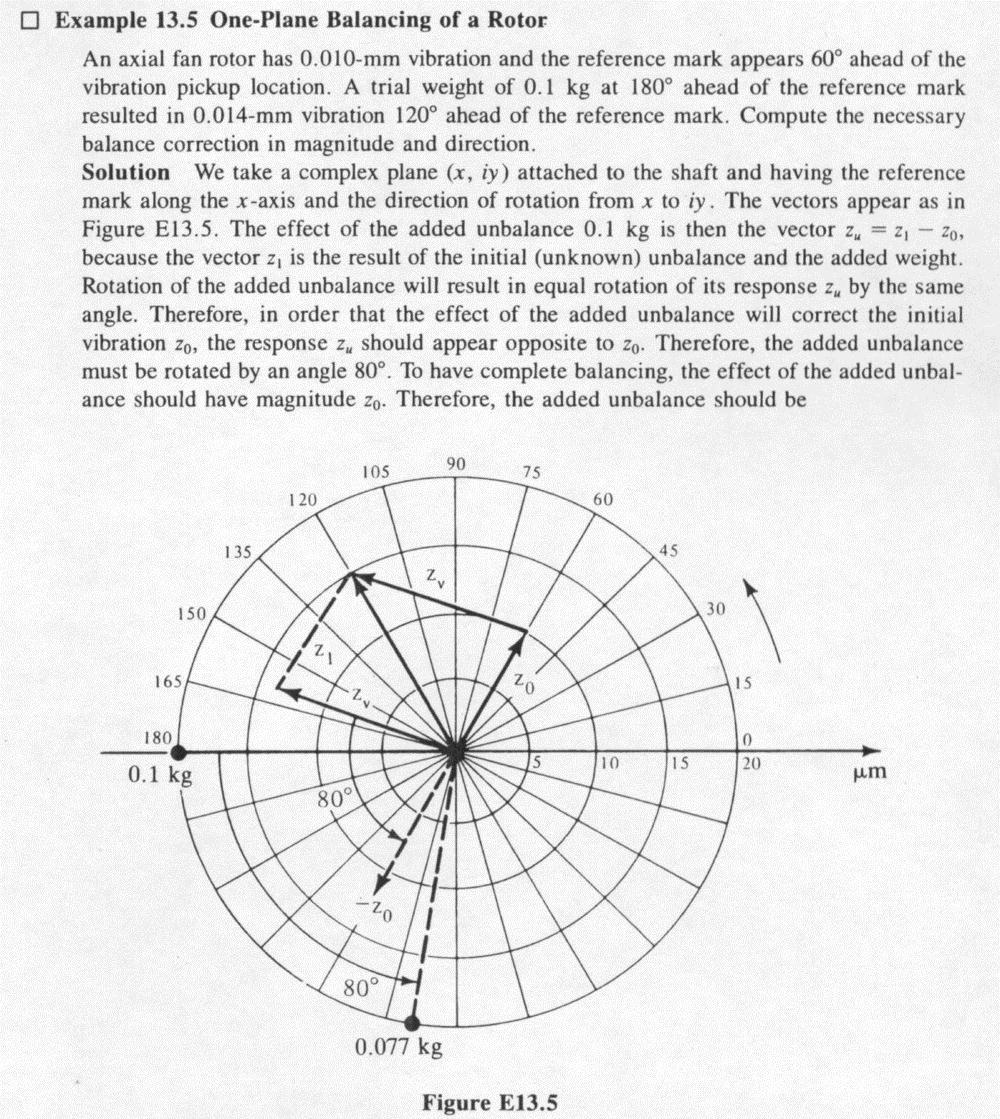
10 APPENDIX B: DETERMINING THE OPTIMAL WEIGHT AND LOCATION TO BALANCE A SHAFT Z 0, Θ 0, Z 1, and Θ 1 are found through measurements with the oscilloscope. With these values known, the optimal weight and location of that weight can be determined to balance the shaft. Refer to Figure B.1 when performing these steps. Figure B.1. Vector diagram for one-plane balancing. 1) First determine Z v using the law of cosines: Z Z Z 2* Z0 * Z1 *cos( ( v 0 1 Z v where Θ(Z v ) = Θ 1 Θ 0. 2) Next determine Φ using the law of sines: Z sin( ( Z v v )) Z1 sin( ) 3) Add Φ to the initial angle of the added mass. This is the optimal location for the added mass. 4) Determine the optimal weight with this equation: m new m old Z Z 0 v )) 10

11 APPENDIX C: ADDITIONAL INFORMATION AND EXAMPLE ON SHAFT BALANCING 11

12 12
EE2210 Laboratory Project 1 Fall 2013 Function Generator and Oscilloscope
 EE2210 Laboratory Project 1 Fall 2013 Function Generator and Oscilloscope For students to become more familiar with oscilloscopes and function generators. Pre laboratory Work Read the TDS 210 Oscilloscope
Laboratory 3 (drawn from lab text by Alciatore)
") Laboratory 3 (drawn from lab text by Alciatore) The Oscilloscope Required Components: 1 10 resistor 2 100 resistors 2 lk resistors 1 2k resistor 2 4.7M resistors 1 0.F capacitor 1 0.1 F capacitor 1 1.0uF
Laboratory 3 (drawn from lab text by Alciatore) The Oscilloscope Required Components: 1 10 resistor 2 100 resistors 2 lk resistors 1 2k resistor 2 4.7M resistors 1 0.F capacitor 1 0.1 F capacitor 1 1.0uF
Magnetism and Induction
 Magnetism and Induction Before the Lab Read the following sections of Giancoli to prepare for this lab: 27-2: Electric Currents Produce Magnetism 28-6: Biot-Savart Law EXAMPLE 28-10: Current Loop 29-1:
Keypad Quick Reference
 Bently Nevada* Asset Condition Monitoring SCOUT100 Series and vbseries Quick Start Guide Precautions Do not attach the accelerometer or tachometer to a high potential voltage source. Do not place the mounting
Laboratory 14. Lab 14. Vibration Measurement With an Accelerometer
 Laboratory 14 Vibration Measurement With an Accelerometer Required Special Equipment: custom-made apparatus consisting of two sets of motors/shafts/bearings mounted on an aluminum plate Endevco 2721B charge
Calibration of Hollow Operating Shaft Natural Frequency by Non-Contact Impulse Method
 IOSR Journal of Mechanical and Civil Engineering (IOSR-JMCE) e-issn: 2278-1684,p-ISSN: 2320-334X, Volume 13, Issue 2 Ver. I (Mar. - Apr. 2016), PP 54-60 www.iosrjournals.org Calibration of Hollow Operating
I = I 0 cos 2 θ (1.1)
") Chapter 1 Faraday Rotation Experiment objectives: Observe the Faraday Effect, the rotation of a light wave s polarization vector in a material with a magnetic field directed along the wave s direction.
Chapter 1 Faraday Rotation Experiment objectives: Observe the Faraday Effect, the rotation of a light wave s polarization vector in a material with a magnetic field directed along the wave s direction.
EE 210: CIRCUITS AND DEVICES
 EE 210: CIRCUITS AND DEVICES LAB #3: VOLTAGE AND CURRENT MEASUREMENTS This lab features a tutorial on the instrumentation that you will be using throughout the semester. More specifically, you will see
Activity P07: Acceleration of a Cart (Acceleration Sensor, Motion Sensor)
") Name Class Date Activity P07: Acceleration of a Cart (Acceleration Sensor, Motion Sensor) Concept DataStudio ScienceWorkshop (Mac) ScienceWorkshop (Win) Linear motion P07 Accelerate Cart.ds (See end of
Name Class Date Activity P07: Acceleration of a Cart (Acceleration Sensor, Motion Sensor) Concept DataStudio ScienceWorkshop (Mac) ScienceWorkshop (Win) Linear motion P07 Accelerate Cart.ds (See end of
Lab #1 Lab Introduction
 Cir cuit s 212 Lab Lab #1 Lab Introduction Special Information for this Lab s Report Because this is a one-week lab, please hand in your lab report for this lab at the beginning of next week s lab. The
UNIVERSITY OF CALIFORNIA, SANTA BARBARA Department of Electrical and Computer Engineering. ECE 2A & 2B Laboratory Equipment Information
 UNIVERSITY OF CALIFORNIA, SANTA BARBARA Department of Electrical and Computer Engineering ECE 2A & 2B Laboratory Equipment Information Table of Contents Digital Multi-Meter (DMM)... 1 Features... 1 Using
Active Vibration Isolation of an Unbalanced Machine Tool Spindle
 Active Vibration Isolation of an Unbalanced Machine Tool Spindle David. J. Hopkins, Paul Geraghty Lawrence Livermore National Laboratory 7000 East Ave, MS/L-792, Livermore, CA. 94550 Abstract Proper configurations
Experiment: P34 Resonance Modes 1 Resonance Modes of a Stretched String (Power Amplifier, Voltage Sensor)
") PASCO scientific Vol. 2 Physics Lab Manual: P34-1 Experiment: P34 Resonance Modes 1 Resonance Modes of a Stretched String (Power Amplifier, Voltage Sensor) Concept Time SW Interface Macintosh file Windows
PASCO scientific Vol. 2 Physics Lab Manual: P34-1 Experiment: P34 Resonance Modes 1 Resonance Modes of a Stretched String (Power Amplifier, Voltage Sensor) Concept Time SW Interface Macintosh file Windows
The Oscilloscope. Vision is the art of seeing things invisible. J. Swift ( ) OBJECTIVE To learn to operate a digital oscilloscope.
 OBJECTIVE To learn to operate a digital oscilloscope.") The Oscilloscope Vision is the art of seeing things invisible. J. Swift (1667-1745) OBJECTIVE To learn to operate a digital oscilloscope. THEORY The oscilloscope, or scope for short, is a device for drawing
The Oscilloscope Vision is the art of seeing things invisible. J. Swift (1667-1745) OBJECTIVE To learn to operate a digital oscilloscope. THEORY The oscilloscope, or scope for short, is a device for drawing
Breadboard Primer. Experience. Objective. No previous electronics experience is required.
 Breadboard Primer Experience No previous electronics experience is required. Figure 1: Breadboard drawing made using an open-source tool from fritzing.org Objective A solderless breadboard (or protoboard)
Experiment P36: Resonance Modes and the Speed of Sound (Voltage Sensor, Power Amplifier)
") PASCO scientific Vol. 2 Physics Lab Manual: P36-1 Experiment P36: Resonance Modes and the Speed of Sound (Voltage Sensor, Power Amplifier) Concept Time SW Interface Macintosh File Windows File waves 45
PASCO scientific Vol. 2 Physics Lab Manual: P36-1 Experiment P36: Resonance Modes and the Speed of Sound (Voltage Sensor, Power Amplifier) Concept Time SW Interface Macintosh File Windows File waves 45
Faculty of Engineering, Thammasat University
 Faculty of Engineering, Thammasat University Experiment 6: Oscilloscope (For room 506) Objectives: 1. To familiarize you with the Oscilloscope and Function Generator User Manual: Oscilloscope 1 5 9 4 7
Laboratory Experiment #2 Frequency Response Measurements
 J.B.Francis College of Engineering Mechanical Engineering Department 22-403 Laboratory Experiment #2 Frequency Response Measurements Introduction It is known from dynamic systems that a structure temporarily
PHY152 Experiment 4: Oscillations in the RC-Circuits (Measurements with an oscilloscope)
") PHY152 Experiment 4: Oscillations in the RC-Circuits (Measurements with an oscilloscope) If you have not used an oscilloscope before, the web site http://www.upscale.utoronto.ca/generalinterest/harrison/oscilloscope/oscilloscope.html
PHY152 Experiment 4: Oscillations in the RC-Circuits (Measurements with an oscilloscope) If you have not used an oscilloscope before, the web site http://www.upscale.utoronto.ca/generalinterest/harrison/oscilloscope/oscilloscope.html
Experiment A2 Galileo s Inclined Plane Procedure
 Experiment A2 Galileo s Inclined Plane Procedure Deliverables: Checked lab notebook, printed plots with captions Overview In the first part of this lab, you will perform Galileo s famous inclined plane
Experiment P55: Light Intensity vs. Position (Light Sensor, Motion Sensor)
") PASCO scientific Vol. 2 Physics Lab Manual: P55-1 Experiment P55: (Light Sensor, Motion Sensor) Concept Time SW Interface Macintosh file Windows file illuminance 30 m 500/700 P55 Light vs. Position P55_LTVM.SWS
PASCO scientific Vol. 2 Physics Lab Manual: P55-1 Experiment P55: (Light Sensor, Motion Sensor) Concept Time SW Interface Macintosh file Windows file illuminance 30 m 500/700 P55 Light vs. Position P55_LTVM.SWS
Introduction to basic laboratory instruments
 BEE 233 Laboratory-1 Introduction to basic laboratory instruments 1. Objectives To learn safety procedures in the laboratory. To learn how to use basic laboratory instruments: power supply, function generator,
Experiment 3 Topic: Dynamic System Response Week A Procedure
 Experiment 3 Topic: Dynamic System Response Week A Procedure Laboratory Assistant: Email: Office Hours: LEX-3 Website: Brock Hedlund bhedlund@nd.edu 11/05 11/08 5 pm to 6 pm in B14 http://www.nd.edu/~jott/measurements/measurements_lab/e3
Experiment P10: Acceleration of a Dynamics Cart II (Motion Sensor)
") PASCO scientific Physics Lab Manual: P10-1 Experiment P10: (Motion Sensor) Concept Time SW Interface Macintosh file Windows file Newton s Laws 30 m 500 or 700 P10 Cart Acceleration II P10_CAR2.SWS EQUIPMENT
PASCO scientific Physics Lab Manual: P10-1 Experiment P10: (Motion Sensor) Concept Time SW Interface Macintosh file Windows file Newton s Laws 30 m 500 or 700 P10 Cart Acceleration II P10_CAR2.SWS EQUIPMENT
Vibration Fundamentals Training System
 Vibration Fundamentals Training System Hands-On Turnkey System for Teaching Vibration Fundamentals An Ideal Tool for Optimizing Your Vibration Class Curriculum The Vibration Fundamentals Training System
EC310 Security Exercise 20
 EC310 Security Exercise 20 Introduction to Sinusoidal Signals This lab demonstrates a sinusoidal signal as described in class. In this lab you will identify the different waveform parameters for a pure
2 Oscilloscope Familiarization
 Lab 2 Oscilloscope Familiarization What You Need To Know: Voltages and currents in an electronic circuit as in a CD player, mobile phone or TV set vary in time. Throughout the course you will investigate
EE 201 Function / Arbitrary Waveform Generator and Oscilloscope Tutorial
 EE 201 Function / Arbitrary Waveform Generator and Oscilloscope Tutorial 1 This is a programmed learning instruction manual. It is written for the Agilent DSO3202A Digital Storage Oscilloscope. The prerequisite
Velleman Arbitrary Function Generator: Windows 7 by Mr. David Fritz
 Velleman Arbitrary Function Generator: Windows 7 by Mr. David Fritz You should already have the drivers installed Launch the scope control software. Start > Programs > Velleman > PcLab2000LT What if the
Lab 3: AC Low pass filters (version 1.3)
") Lab 3: AC Low pass filters (version 1.3) WARNING: Use electrical test equipment with care! Always double-check connections before applying power. Look for short circuits, which can quickly destroy expensive
Lab 3: AC Low pass filters (version 1.3) WARNING: Use electrical test equipment with care! Always double-check connections before applying power. Look for short circuits, which can quickly destroy expensive
Giraud Tool Company, Inc.
 Motor Upgrade for Gracey Trimmer This package is intended to allow the user to upgrade their Gracey trimmer with a higher rpm motor and convenience features not found in the production offering. This upgrade
Press Cursors and use the appropriate X and Y functions to measure period and peak-peak voltage of the square wave.
 Equipment Review To assure that everyone is up to speed for the hurdles ahead, the first lab of the semester is traditionally an easy review of electrical laboratory fundamentals. There will, however,
Experiment P49: Transistor Lab 2 Current Gain: The NPN Emitter-Follower Amplifier (Power Amplifier, Voltage Sensor)
") PASCO scientific Vol. 2 Physics Lab Manual: P49-1 Experiment P49: Transistor Lab 2 Current Gain: The NPN Emitter-Follower Amplifier (Power Amplifier, Voltage Sensor) Concept Time SW Interface Macintosh
PASCO scientific Vol. 2 Physics Lab Manual: P49-1 Experiment P49: Transistor Lab 2 Current Gain: The NPN Emitter-Follower Amplifier (Power Amplifier, Voltage Sensor) Concept Time SW Interface Macintosh
Radiation characteristics of an array of two dipole antennas
 Department of Electrical and Electronic Engineering (EEE), Bangladesh University of Engineering and Technology (BUET). EEE 434: Microwave Engineering Laboratory Experiment No.: A2 Radiation characteristics
Lab #5 Steady State Power Analysis
 Lab #5 Steady State Power Analysis Steady state power analysis refers to the power analysis of circuits that have one or more sinusoid stimuli. This lab covers the concepts of RMS voltage, maximum power
Experiment #2: Introduction to Lab Equipment: Function Generator, Oscilloscope, and Multisim
 SCHOOL OF ENGINEERING AND APPLIED SCIENCE DEPARTMENT OF ELECTRICAL AND COMPUTER ENGINEERING ECE 2110: CIRCUIT THEORY LABORATORY Experiment #2: Introduction to Lab Equipment: Function Generator, Oscilloscope,
EENG-201 Experiment # 4: Function Generator, Oscilloscope
 EENG-201 Experiment # 4: Function Generator, Oscilloscope I. Objectives Upon completion of this experiment, the student should be able to 1. To become familiar with the use of a function generator. 2.
Analog Discovery Arbitrary Function Generator for Windows 7 by Mr. David Fritz and Ms. Ellen Robertson
 Analog Discovery Arbitrary Function Generator for Windows 7 by Mr. David Fritz and Ms. Ellen Robertson Financial support to develop this tutorial was provided by the Bradley Department of Electrical and
Exercise 4 - THE OSCILLOSCOPE
 Exercise 4 - THE OSCILLOSCOPE INTRODUCTION You have been exposed to analogue oscilloscopes in the first year lab. As you are probably aware, the complexity of the instruments, along with their importance
LAB 7: THE OSCILLOSCOPE
 LAB 7: THE OSCILLOSCOPE Equipment List: Dual Trace Oscilloscope HP function generator HP-DMM 2 BNC-to-BNC 1 cables (one long, one short) 1 BNC-to-banana 1 BNC-probe Hand-held DMM (freq mode) Purpose: To
Ph 3455 The Franck-Hertz Experiment
 Ph 3455 The Franck-Hertz Experiment Required background reading Tipler, Llewellyn, section 4-5 Prelab Questions 1. In this experiment, we will be using neon rather than mercury as described in the textbook.
BME/ISE 3511 Laboratory One - Laboratory Equipment for Measurement. Introduction to biomedical electronic laboratory instrumentation and measurements.
 BME/ISE 3511 Laboratory One - Laboratory Equipment for Measurement Learning Objectives: Introduction to biomedical electronic laboratory instrumentation and measurements. Supplies and Components: Breadboard
Group: Names: (1) In this step you will examine the effects of AC coupling of an oscilloscope.
 In this step you will examine the effects of AC coupling of an oscilloscope.") 3.5 Laboratory Procedure / Summary Sheet Group: Names: (1) In this step you will examine the effects of AC coupling of an oscilloscope. Set the function generator to produce a 5 V pp 1kHz sinusoidal output.
3.5 Laboratory Procedure / Summary Sheet Group: Names: (1) In this step you will examine the effects of AC coupling of an oscilloscope. Set the function generator to produce a 5 V pp 1kHz sinusoidal output.
ENGR 1110: Introduction to Engineering Lab 7 Pulse Width Modulation (PWM)
") ENGR 1110: Introduction to Engineering Lab 7 Pulse Width Modulation (PWM) Supplies Needed Motor control board, Transmitter (with good batteries), Receiver Equipment Used Oscilloscope, Function Generator,
ENGR 1110: Introduction to Engineering Lab 7 Pulse Width Modulation (PWM) Supplies Needed Motor control board, Transmitter (with good batteries), Receiver Equipment Used Oscilloscope, Function Generator,
Experiment A2 Galileo s Inclined Plane Procedure
 Experiment A2 Galileo s Inclined Plane Procedure Deliverables: Checked lab notebook, Full lab report (including the deliverables from A1) Overview In the first part of this lab, you will perform Galileo
ME 365 EXPERIMENT 1 FAMILIARIZATION WITH COMMONLY USED INSTRUMENTATION
 Objectives: ME 365 EXPERIMENT 1 FAMILIARIZATION WITH COMMONLY USED INSTRUMENTATION The primary goal of this laboratory is to study the operation and limitations of several commonly used pieces of instrumentation:
Legacy Woodworking Machinery a division of Phantom Engineering. The Legacy CNC. Assembly Manual
 Legacy Woodworking Machinery a division of Phantom Engineering The Legacy CNC Assembly Manual New Orientation of the Legacy Step one: Re-orientation of the machine Remove the X-axis screw and supports.
Vibration Analysis on Rotating Shaft using MATLAB
 IJSTE - International Journal of Science Technology & Engineering Volume 3 Issue 06 December 2016 ISSN (online): 2349-784X Vibration Analysis on Rotating Shaft using MATLAB K. Gopinath S. Periyasamy PG
Removing outter components
 Y Axis Motor Replacement Replacing the Y axis motor is a process that requires the individual to be somewhat mechanically inclined and can follow detailed instructions. If any of the following steps are
Quick Start Guide. Contents
 1 Quick Start Guide Contents Powering on the Machine Login/Password Entry Jaw Set Up High Security Cut by Code High Security Jaw Set Up Edge Cut Cut by Code Edge Cut Cut by Decode Cutter Replacement Tracer
DC and AC Circuits. Objective. Theory. 1. Direct Current (DC) R-C Circuit
 R-C Circuit") [International Campus Lab] Objective Determine the behavior of resistors, capacitors, and inductors in DC and AC circuits. Theory ----------------------------- Reference -------------------------- Young
[International Campus Lab] Objective Determine the behavior of resistors, capacitors, and inductors in DC and AC circuits. Theory ----------------------------- Reference -------------------------- Young
UCE-DSO210 DIGITAL OSCILLOSCOPE USER MANUAL. FATIH GENÇ UCORE ELECTRONICS REV1
 UCE-DSO210 DIGITAL OSCILLOSCOPE USER MANUAL FATIH GENÇ UCORE ELECTRONICS www.ucore-electronics.com 2017 - REV1 Contents 1. Introduction... 2 2. Turn on or turn off... 3 3. Oscilloscope Mode... 3 3.1. Display
UCE-DSO212 DIGITAL OSCILLOSCOPE USER MANUAL. UCORE ELECTRONICS
 UCE-DSO212 DIGITAL OSCILLOSCOPE USER MANUAL UCORE ELECTRONICS www.ucore-electronics.com 2017 Contents 1. Introduction... 2 2. Turn on or turn off... 3 3. Oscilloscope Mode... 4 3.1. Display Description...
PHYS 3322 Modern Laboratory Methods I AC R, RC, and RL Circuits
 Purpose PHYS 3322 Modern Laboratory Methods I AC, C, and L Circuits For a given frequency, doubling of the applied voltage to resistors, capacitors, and inductors doubles the current. Hence, each of these
Experiment P11: Newton's Second Law Constant Force (Force Sensor, Motion Sensor)
") PASCO scientific Physics Lab Manual: P11-1 Experiment P11: Newton's Second Law Constant Force (Force Sensor, Motion Sensor) Concept Time SW Interface Macintosh file Windows file Newton s Laws 30 m 500
PASCO scientific Physics Lab Manual: P11-1 Experiment P11: Newton's Second Law Constant Force (Force Sensor, Motion Sensor) Concept Time SW Interface Macintosh file Windows file Newton s Laws 30 m 500
Standing Waves in Air
 Standing Waves in Air Objective Students will explore standing wave phenomena through sound waves in an air tube. Equipment List PASCO resonance tube with speaker and microphone, PASCO PI-9587B Digital
LAB 8: Activity P52: LRC Circuit
 LAB 8: Activity P52: LRC Circuit Equipment: Voltage Sensor 1 Multimeter 1 Patch Cords 2 AC/DC Electronics Lab (100 μf capacitor; 10 Ω resistor; Inductor Coil; Iron core; 5 inch wire lead) The purpose of
Experiment P50: Transistor Lab 3 Common-Emitter Amplifier (Power Amplifier, Voltage Sensor)
") PASCO scientific Vol. 2 Physics Lab Manual: P50-1 Experiment P50: Transistor Lab 3 Common-Emitter Amplifier (Power Amplifier, Voltage Sensor) Concept Time SW Interface Macintosh file Windows file semiconductors
PASCO scientific Vol. 2 Physics Lab Manual: P50-1 Experiment P50: Transistor Lab 3 Common-Emitter Amplifier (Power Amplifier, Voltage Sensor) Concept Time SW Interface Macintosh file Windows file semiconductors
Preliminary study of the vibration displacement measurement by using strain gauge
 Songklanakarin J. Sci. Technol. 32 (5), 453-459, Sep. - Oct. 2010 Original Article Preliminary study of the vibration displacement measurement by using strain gauge Siripong Eamchaimongkol* Department
Physics 1021 Experiment 3. Sound and Resonance
 1 Physics 1021 Sound and Resonance 2 Sound and Resonance Introduction In today's experiment, you will examine beat frequency using tuning forks, a microphone and LoggerPro. You will also produce resonance
Agilent 33522A Function Arbitrary Waveform Generator. Tektronix TDS 3012B Oscilloscope
 Agilent 33522A Function/Arbitrary Waveform Generator and Tektronix TDS 3012B Oscilloscope Agilent 33522A Function Arbitrary Waveform Generator The signal source for this lab is the Agilent 33522A Function
What are we looking at?
 What are we looking at? What are our Goals: Accurate information to provide: Machinery Condition Monitoring Machinery Diagnostics Machinery Reliability Improvements Etc. Probe Coil Types 3000 and 7000
ECE 4670 Spring 2014 Lab 1 Linear System Characteristics
 ECE 4670 Spring 2014 Lab 1 Linear System Characteristics 1 Linear System Characteristics The first part of this experiment will serve as an introduction to the use of the spectrum analyzer in making absolute
PHYSICS 171 UNIVERSITY PHYSICS LAB II. Experiment 4. Alternating Current Measurement
 PHYSICS 171 UNIVERSITY PHYSICS LAB II Experiment 4 Alternating Current Measurement Equipment: Supplies: Oscilloscope, Function Generator. Filament Transformer. A sine wave A.C. signal has three basic properties:
LAB #7: Digital Signal Processing
 LAB #7: Digital Signal Processing Equipment: Pentium PC with NI PCI-MIO-16E-4 data-acquisition board NI BNC 2120 Accessory Box VirtualBench Instrument Library version 2.6 Function Generator (Tektronix
The oscilloscope and RC filters
 (ta initials) first name (print) last name (print) brock id (ab17cd) (lab date) Experiment 4 The oscilloscope and C filters The objective of this experiment is to familiarize the student with the workstation
Resistance Apparatus EM-8812
 Instruction Manual with Experiment Guide and Teachers Notes 012-09573A Resistance Apparatus EM-8812 Resistance Apparatus Table of Contents Contents Introduction...........................................................
Lab Reference Manual. ECEN 326 Electronic Circuits. Texas A&M University Department of Electrical and Computer Engineering
 Lab Reference Manual ECEN 326 Electronic Circuits Texas A&M University Department of Electrical and Computer Engineering Contents 1. Circuit Analysis in PSpice 3 1.1 Transient and DC Analysis 3 1.2 Measuring
Lab 4 An FPGA Based Digital System Design ReadMeFirst
 Lab 4 An FPGA Based Digital System Design ReadMeFirst Lab Summary This Lab introduces a number of Matlab functions used to design and test a lowpass IIR filter. As you have seen in the previous lab, Simulink
Experiment 2: Electronic Enhancement of S/N and Boxcar Filtering
 Experiment 2: Electronic Enhancement of S/N and Boxcar Filtering Synopsis: A simple waveform generator will apply a triangular voltage ramp through an R/C circuit. A storage digital oscilloscope, or an
PHYSICS 326 LAB # 1: The Oscilloscope and Signal Generators 1/6
 PHYSICS 326 LAB # 1: The Oscilloscope and Signal Generators 1/6 PURPOSE: To be sure that each student begins the course with at least the minimum required knowledge of two instruments which we will be
Experiment 3 Topic: Dynamic System Response Week A Procedure
 Experiment 3 Topic: Dynamic System Response Week A Procedure Laboratory Assistant: Email: Office Hours: LEX-3 Website: Caitlyn Clark and Brock Hedlund cclark20@nd.edu, bhedlund@nd.edu 04/03 04/06 from
Activity P56: Transistor Lab 2 Current Gain: The NPN Emitter-Follower Amplifier (Power Output, Voltage Sensor)
") Activity P56: Transistor Lab 2 Current Gain: The NPN Emitter-Follower Amplifier (Power Output, Voltage Sensor) Concept DataStudio ScienceWorkshop (Mac) ScienceWorkshop (Win) Semiconductors P56 Emitter
Activity P56: Transistor Lab 2 Current Gain: The NPN Emitter-Follower Amplifier (Power Output, Voltage Sensor) Concept DataStudio ScienceWorkshop (Mac) ScienceWorkshop (Win) Semiconductors P56 Emitter
Introduction to Lab Instruments
 ECE316, Experiment 00, 2017 Communications Lab, University of Toronto Introduction to Lab Instruments Bruno Korst - bkf@comm.utoronto.ca Abstract This experiment will review the use of three lab instruments
Sound Wave Measurements using an Oscilloscope and Waveform Generator
 Sound Wave Measurements using an Oscilloscope and Waveform Generator In this module students will learn to make sound wave measurements using an oscilloscope and a function generator. This equipment will
Experiment 8: An AC Circuit
 Experiment 8: An AC Circuit PART ONE: AC Voltages. Set up this circuit. Use R = 500 Ω, L = 5.0 mh and C =.01 μf. A signal generator built into the interface provides the emf to run the circuit from Output
Sonoma State University Department of Engineering Science Spring 2017
 EE 110 Introduction to Engineering & Laboratory Experience Saeid Rahimi, Ph.D. Lab 4 Introduction to AC Measurements (I) AC signals, Function Generators and Oscilloscopes Function Generator (AC) Battery
Tektronix digital oscilloscope, BK Precision Function Generator, coaxial cables, breadboard, the crystal earpiece from your AM radio kit.
 Experiment 0: Review I. References The 174 and 275 Lab Manuals Any standard text on error analysis (for example, Introduction to Error Analysis, J. Taylor, University Science Books, 1997) The manual for
Activity P52: LRC Circuit (Voltage Sensor)
") Activity P52: LRC Circuit (Voltage Sensor) Concept DataStudio ScienceWorkshop (Mac) ScienceWorkshop (Win) AC circuits P52 LRC Circuit.DS (See end of activity) (See end of activity) Equipment Needed Qty
Activity P52: LRC Circuit (Voltage Sensor) Concept DataStudio ScienceWorkshop (Mac) ScienceWorkshop (Win) AC circuits P52 LRC Circuit.DS (See end of activity) (See end of activity) Equipment Needed Qty
Lab 6 Instrument Familiarization
 Lab 6 Instrument Familiarization What You Need To Know: Voltages and currents in an electronic circuit as in a CD player, mobile phone or TV set vary in time. Throughout todays lab you will investigate
Experiment A8 Electronics III Procedure
 Experiment A8 Electronics III Procedure Deliverables: checked lab notebook, plots Overview Electronics have come a long way in the last century. Using modern fabrication techniques, engineers can now print
Experiment A8 Electronics III Procedure
 Experiment A8 Electronics III Procedure Deliverables: checked lab notebook, plots Overview Electronics have come a long way in the last century. Using modern fabrication techniques, engineers can now print
Activity P40: Driven Harmonic Motion - Mass on a Spring (Force Sensor, Motion Sensor, Power Amplifier)
") Name Class Date Activity P40: Driven Harmonic Motion - Mass on a Spring (Force Sensor, Motion Sensor, Power Amplifier) Concept DataStudio ScienceWorkshop (Mac) ScienceWorkshop (Win) Harmonic motion P40
Name Class Date Activity P40: Driven Harmonic Motion - Mass on a Spring (Force Sensor, Motion Sensor, Power Amplifier) Concept DataStudio ScienceWorkshop (Mac) ScienceWorkshop (Win) Harmonic motion P40
CHAPTER 5 FAULT DIAGNOSIS OF ROTATING SHAFT WITH SHAFT MISALIGNMENT
 66 CHAPTER 5 FAULT DIAGNOSIS OF ROTATING SHAFT WITH SHAFT MISALIGNMENT 5.1 INTRODUCTION The problem of misalignment encountered in rotating machinery is of great concern to designers and maintenance engineers.
Activity P57: Transistor Lab 3 Common-Emitter Amplifier (Voltage Sensor)
") Activity P57: Transistor Lab 3 Common-Emitter Amplifier (Voltage Sensor) Concept DataStudio ScienceWorkshop (Mac) ScienceWorkshop (Win) Semiconductors P57 Common Emitter.DS (See end of activity) (See end
Activity P57: Transistor Lab 3 Common-Emitter Amplifier (Voltage Sensor) Concept DataStudio ScienceWorkshop (Mac) ScienceWorkshop (Win) Semiconductors P57 Common Emitter.DS (See end of activity) (See end
Momentum and Impulse. Objective. Theory. Investigate the relationship between impulse and momentum.
 [For International Campus Lab ONLY] Objective Investigate the relationship between impulse and momentum. Theory ----------------------------- Reference -------------------------- Young & Freedman, University
Experiment 15: Diode Lab Part 1
 Experiment 15: Diode Lab Part 1 Purpose Theory Overview EQUIPMENT NEEDED: Computer and Science Workshop Interface Power Amplifier (CI-6552A) (2) Voltage Sensor (CI-6503) AC/DC Electronics Lab Board (EM-8656)
Lab E5: Filters and Complex Impedance
 E5.1 Lab E5: Filters and Complex Impedance Note: It is strongly recommended that you complete lab E4: Capacitors and the RC Circuit before performing this experiment. Introduction Ohm s law, a well known
Lab E5: Filters and Complex Impedance
 E5.1 Lab E5: Filters and Complex Impedance Note: It is strongly recommended that you complete lab E4: Capacitors and the RC Circuit before performing this experiment. Introduction Ohm s law, a well known
EXPERIMENT NUMBER 2 BASIC OSCILLOSCOPE OPERATIONS
 1 EXPERIMENT NUMBER 2 BASIC OSCILLOSCOPE OPERATIONS The oscilloscope is the most versatile and most important tool in this lab and is probably the best tool an electrical engineer uses. This outline guides
UNIVERSITY OF WATERLOO Physics 360/460 Experiment #2 ATOMIC FORCE MICROSCOPY
 UNIVERSITY OF WATERLOO Physics 360/460 Experiment #2 ATOMIC FORCE MICROSCOPY References: http://virlab.virginia.edu/vl/home.htm (University of Virginia virtual lab. Click on the AFM link) An atomic force
Experiment 1 Alternating Current with Coil and Ohmic Resistors
 Experiment Alternating Current with Coil and Ohmic esistors - Objects of the experiment - Determining the total impedance and the phase shift in a series connection of a coil and a resistor. - Determining
Electric Drives Experiment 5 Four-Quadrant Operation of a PMDC Motor
 Electric Drives Experiment 5 Four-Quadrant Operation of a PMDC Motor 5.1 Objective The objective of this activity is to analyze the four-quadrant operation of a permanent-magnet DC (PMDC) motor. This activity
Spectrum Analysis: The FFT Display
 Spectrum Analysis: The FFT Display Equipment: Capstone, voltage sensor 1 Introduction It is often useful to represent a function by a series expansion, such as a Taylor series. There are other series representations
Lab 3: RC Circuits. Construct circuit 2 in EveryCircuit. Set values for the capacitor and resistor to match those in figure 2 and set the frequency to
 Lab 3: RC Circuits Prelab Deriving equations for the output voltage of the voltage dividers you constructed in lab 2 was fairly simple. Now we want to derive an equation for the output voltage of a circuit
Teacher s Guide - Activity P51: LR Circuit (Power Output, Voltage Sensor)
") Teacher s Guide - Activity P51: LR Circuit (Power Output, Voltage Sensor) Concept DataStudio ScienceWorkshop (Mac) ScienceWorkshop (Win) Circuits P51 LR Circuit.DS (See end of activity) (See end of activity)
Teacher s Guide - Activity P51: LR Circuit (Power Output, Voltage Sensor) Concept DataStudio ScienceWorkshop (Mac) ScienceWorkshop (Win) Circuits P51 LR Circuit.DS (See end of activity) (See end of activity)
Electromagnetic Induction - A
 Electromagnetic Induction - A APPARATUS 1. Two 225-turn coils 2. Table Galvanometer 3. Rheostat 4. Iron and aluminum rods 5. Large circular loop mounted on board 6. AC ammeter 7. Variac 8. Search coil
EXPERIMENT NUMBER 8 Introduction to Active Filters
 EXPERIMENT NUMBER 8 Introduction to Active Filters i-1 Preface: Preliminary exercises are to be done and submitted individually. Laboratory hardware exercises are to be done in groups. This laboratory
sin(wt) y(t) Exciter Vibrating armature ENME599 1
 y(t) Exciter Vibrating armature ENME599 1") ENME599 1 LAB #3: Kinematic Excitation (Forced Vibration) of a SDOF system Students must read the laboratory instruction manual prior to the lab session. The lab report must be submitted in the beginning
ENME599 1 LAB #3: Kinematic Excitation (Forced Vibration) of a SDOF system Students must read the laboratory instruction manual prior to the lab session. The lab report must be submitted in the beginning
Name: First-Order Response: RC Networks Objective: To gain experience with first-order response of RC circuits
 First-Order Response: RC Networks Objective: To gain experience with first-order response of RC circuits Table of Contents: Pre-Lab Assignment 2 Background 2 National Instruments MyDAQ 2 Resistors 3 Capacitors