EE290C - Spring 2004 Advanced Topics in Circuit Design
|
|
|
- Piers Griffith
- 5 years ago
- Views:
Transcription
1 EE290C - Spring 2004 Advanced Topics in Circuit Design Lecture #3 Measurements with VNA and TDR Ben Chia Tu-Th 4 5:30pm 531 Cory Agenda Relationships between time domain and frequency domain TDR Time Domain Instrument VNA Frequency Domain Instrument 2
2 Time and Frequency Domain Measurement Relationships between time domain and frequency domain TDR Time Domain Instrument VNA Frequency Domain Instrument 3 Time Domain and Frequency Domain 4
3 Time Domain and Frequency Domain 5 Time and Frequency Domain Measurement Relationships between time domain and frequency domain VNA Frequency Domain Instrument TDR Time Domain Instrument 6

4 Agilent 8722ES Vector Network Analyzer 7 Vector Network Analyzer ( VNA ) A frequency Domain Instrument Sin wave generators on all ports Receive Sampling circuit on all ports Need Calibration Can measure delay, loss at different frequencies 8
5 S Parameter 9 Vector Network Analyzer ( VNA ) 10
6 VNA Setup Warm up the VNA for one hour Connect RF cables with torque wrench Set start and stop frequency Set number of sampling point Set the average to 4 Start Calibration. 11 What is the purpose of VNA calibration? Establish reference plane Remove any unwanted measurement error, including cable and connections Short/open/load standard Through standard Reference Plane 12
7 What is reference plane? VNA will measure the response starting at the reference plane SMA Connector Reference plane Coax Connected to VNA PCB trace or Device Under Test Calibration remove all loss, delay, reflection from the measurement results before this plane 13 VNA 3.5MM SMA Calibration Enter Calibration Kit standard table Cal Cal Kit Modify[2.4mm] Define Standard Modify STD Definition Specify Offset Offset Delay Calibrate VNA with Open, Short, Load Standards Cal Calibrate Menu Full two port Reflection Check the validity of calibration Measure Standard Cal Kit Measure known transmission line 14

8 STD Definitions from Kit Vendor 15 VNA Through Standard Open Standard short Standard 50 ohm Standard Open Standard Through Standard 16

9 What is Smith Chart? 17 Open, Short, Load Calibration 18


10 Calibration check : open standard S22 curve should not go outside of smith chart 19 Calibration check : short standard S22 curve should not go outside of smith chart 20

11 Calibration check : 50 ohm standard S22 should have one dot in the middle of chart 21 PCB Through and stub Via Pcb surface layer trace PCB cross section Ch#1 Ch#2 Through via Pcb surface layer trace Ch#1 Ch#2 Stub via 22


12 S21 of Through Via 23 VNA S11 through Via ( Smaller Reflection ) 24
")
 Stub via")
13 VNA S21 Stub Via 25 S21 Stub Via (red) and Through Via(Yellow) Stub via Has More loss 26


14 S21 of Stub Via ( Larger Reflection ) 27 VNA Through Via 28


15 VNA Stub Via 29 S21 of a 3 inch PCB trace 30


16 S11 of a 3-inch Trace 31 S11 of a 4.8" inch PCB trace 32


17 S21 of a 4.8 inch PCB trace 33 S11 of 3 (Red) and 4.7 (Yellow) Traced 34
")
18 Time and Frequency Domain Measurement Relationships between time domain and frequency domain VNA Frequency Domain Instrument TDR Time Domain Instrument 35 Time Domain Reflectometer (TDR) 36
19 TDR: Time Domain Reflectometer TDR is time domain instrument based on the principle of wave reflections Used mainly for Impedance measurement Can measure propagation delay TDR needs require calibration before use 37 Reflection Coefficient Ei: Incident wave amplitude Er: Reflected wave amplitude Zo ZL 38
20 Different types of reflections 39 TDR Operation TDR T D 40

21 TDR Calibration Procedure Turn on TDR for 30 minutes before measurement Prepare Calibration Standard Short standard and 50 ohm standard Get good quality RF cables Discharge cables before connecting to TDR Select TDR mode of operation Push TDR Setup Turn on Stimulus 41 TDR Plug-in Module TDR Setup 42


22 TDR screen showing an incident wave leaving TDR 43 TDR with open-end cable This circle is shown on the next page) Reflected wave seen by TDR Incident wave Round trip delay time of coax cable 44


23 TDR Reflected Edge of an Open Transmission Line 45 TDR Reflected Edge of an short Transmission Line 46
24 What is the purpose of TDR calibration? Calibration establishes the starting point of the wave, which is also the start time of the measurement 50 ohm cable To TDR SMA Connector Wave direction Reference plane ( wave starting point ) How does the TDR know this is the starting point? 47 By a known standard at the reference plane Short = cable connected to ground 50 ohm = cable connected to 50 ohm load To TDR SMA Connector Short standard 50 ohm cable To TDR 50 ohm cable SMA Connector 50 ohm standard 48

25 TDR: Calibration Procedures Select Normalization Key Adjust Rise time Select Normalization and Reference Plane Follow instructions on the screen Short and load normalization Turn on Normalized Channel Done 49 TDR Reference Plane for Calibration 50


26 TDR edge rate 200ps/2ns/4ns 51 TDR Impedance Marker 52
27 Crosstalk of two adjacent PCB traces Channel 1 drives open-end pcb trace Channel 2 is not connected 53 Cross Talk TDR Channel #1(stimulus) 50 ohm TDR Channel #1(stimulus) TDR Channel #2 Far End Cross Talk TDR Channel #2 Near End Cross Talk 50 ohm 54


28 Far End Crosstalk 55 Near End Cross Talk 56


29 Differential TDR Reset State 57 Differential TDR Reflected wave from an open-end cable 58

30 Differential TDR of trace + connector + trace Connector TDR probing point Two Traces in parallel 59 Differential TDR of trace + connector + trace 60


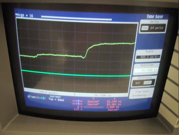
31 TDR for delay measurement: open-end cable 61 TDR connected to an open-end short trace 62

32 TDR connected to two open-end short and long traces Delay = Time Difference / 2 63 Summary TDR measures signal in the time domain VNA measures signal in the frequency domain Both TDR and VNA requires Calibration to determine the reference plane and to remove measurement errors Reference Test and Meaurement Library 64
Network Analysis Basics
 Adolfo Del Solar Application Engineer adolfo_del-solar@agilent.com MD1010 Network B2B Agenda Overview What Measurements do we make? Network Analyzer Hardware Error Models and Calibration Example Measurements
RF Characterization Report
 SMA-J-P-H-ST-MT1 Mated with: RF316-01SP1-01BJ1-0305 Description: 50-Ω SMA Board Mount Jack, Mixed Technology Samtec, Inc. 2005 All Rights Reserved Table of Contents Introduction...1 Product Description...1
High Speed Competitive Comparison Report. Samtec MMCX-J-P-H-ST-TH1 Mated With MMCX-P-P-H-ST-TH1 Competitor A (Mated Set) Competitor B (Mated Set)
 Competitor B (Mated Set)") High Speed Competitive Comparison Report Samtec MMCX-J-P-H-ST-TH1 Mated With MMCX-P-P-H-ST-TH1 Competitor A (Mated Set) Competitor B (Mated Set) REVISION DATE: January 6, 2005 TABLE OF CONTENTS Introduction...
High Speed Competitive Comparison Report Samtec MMCX-J-P-H-ST-TH1 Mated With MMCX-P-P-H-ST-TH1 Competitor A (Mated Set) Competitor B (Mated Set) REVISION DATE: January 6, 2005 TABLE OF CONTENTS Introduction...
High Speed Characterization Report
 High Speed Characterization Report MMCX-P-P-H-ST-TH1 mated with MMCX-J-P-H-ST-TH1 MMCX-P-P-H-ST-MT1 mated with MMCX-J-P-H-ST-MT1 MMCX-P-P-H-ST-SM1 mated with MMCX-J-P-H-ST-SM1 MMCX-P-P-H-ST-EM1 mated with
Circuit Characterization with the Agilent 8714 VNA
 Circuit Characterization with the Agilent 8714 VNA By: Larry Dunleavy Wireless and Microwave Instruments University of South Florida Objectives 1) To examine the concepts of reflection, phase shift, attenuation,
Validation Report Comparison of Eye Patterns Generated By Synopsys HSPICE and the Agilent PLTS
 Comparison of Eye Patterns Generated By Synopsys HSPICE and the Agilent PLTS Using: Final Inch Test/Eval Kit, Differential Pair - No Grounds Configuration, QTE-DP/QSE-DP, 5mm Stack Height (P/N FIK-QxE-04-01)
High Speed Characterization Report
 HDLSP-035-2.00 Mated with: HDI6-035-01-RA-TR/HDC-035-01 Description: High Density/High Speed IO Cable Assembly Samtec, Inc. 2005 All Rights Reserved Table of Contents Introduction...1 Product Description...1
Calibration and De-Embedding Techniques in the Frequency Domain
 Calibration and De-Embedding Techniques in the Frequency Domain Tom Dagostino tom@teraspeed.com Alfred P. Neves al@teraspeed.com Page 1 Teraspeed Labs Teraspeed Consulting Group LLC 2008 Teraspeed Consulting
High Speed Characterization Report
 PCRF-064-1000-SMA-P-1 Mated with: PCIE-XXX-02-X-D-TH and SMA-J-P-X-ST-TH1 Description: Cable Assembly, Low Loss Microwave Coax, PCI Express Breakout Samtec, Inc. 2005 All Rights Reserved Table of Contents
High Speed Characterization Report
 TCDL2-10-T-05.00-DP and TCDL2-10-T-10.00-DP Mated with: TMMH-110-04-X-DV and CLT-110-02-X-D Description: 2-mm Pitch Micro Flex Data Link Samtec, Inc. 2005 All Rights Reserved Table of Contents Introduction...1
Signal Integrity Testing with a Vector Network Analyzer. Neil Jarvis Applications Engineer
 Signal Integrity Testing with a Vector Network Analyzer Neil Jarvis Applications Engineer 1 Agenda RF Connectors A significant factor in repeatability and accuracy Selecting the best of several types for
Measuring PCB, Cable and Interconnect Impedance, Dielectric Constants, Velocity Factor, and Lengths
 Measuring PCB, Cable and Interconnect Impedance, Dielectric Constants, Velocity Factor, and Lengths Controlled impedance printed circuit boards (PCBs) often include a measurement coupon, which typically
Agilent Accurate Measurement of Packaged RF Devices. White Paper
 Agilent Accurate Measurement of Packaged RF Devices White Paper Slide #1 Slide #2 Accurate Measurement of Packaged RF Devices How to Measure These Devices RF and MW Device Test Seminar 1995 smafilt.tif
TEST EQUIPMENT PLUS. Signal Hound USB-SA44B / USB-TG44A. Application Note 1: The Smith Chart. Rev. 0
 Rev. 0 TEST EQUIPMENT PLUS Signal Hound USB-SA44B / USB-TG44A Application Note 1: The Smith Chart USING THE SMITH CHART Chapter 1 1 Using the Smith Chart Making Single-Frequency Vector Impedance Measurements
Signal Integrity Tips and Techniques Using TDR, VNA and Modeling. Russ Kramer O.J. Danzy
 Signal Integrity Tips and Techniques Using TDR, VNA and Modeling Russ Kramer O.J. Danzy Simulation What is the Signal Integrity Challenge? Tx Rx Channel Asfiakhan Dreamstime.com - 3d People Communication
High Data Rate Characterization Report
 High Data Rate Characterization Report EQCD-020-39.37-STR-TTL-1 EQCD-020-39.37-STR-TEU-2 Mated with: QTE-020-01-X-D-A and QSE-020-01-X-D-A Description: 0.8mm High-Speed Coax Cable Assembly Samtec, Inc.
High Data Rate Characterization Report
 High Data Rate Characterization Report VPSTP-016-1000-01 Mated with: VRDPC-50-01-M-RA and VRDPC-50-01-M-RA Description: Plug Shielded Twisted Pair Cable Assembly, 0.8mm Pitch Samtec, Inc. 2005 All Rights
EXPERIMENT EM3 INTRODUCTION TO THE NETWORK ANALYZER
 ECE 351 ELECTROMAGNETICS EXPERIMENT EM3 INTRODUCTION TO THE NETWORK ANALYZER OBJECTIVE: The objective to this experiment is to introduce the student to some of the capabilities of a vector network analyzer.
Reflectometer Series:
 Reflectometer Series: R54, R60 & R140 Vector Network Analyzers Clarke & Severn Electronics Ph +612 9482 1944 Email sales@clarke.com.au BUY NOW - www.cseonline.com.au KEY FEATURES Patent: US 9,291,657 No
Network Analysis Seminar. Cables measurement
 Network Analysis Seminar Cables measurement Agenda 1. Device Under Test: Cables & Connectors 2. Instrument for cables testing: Network Analyzer 3. Measurement: Frequency Domain 4. Measurement: Time Domain
Tektronix Inc. DisplayPort Standard. Revision Tektronix MOI for Cable Tests (DSA8200 based sampling instrument with IConnect software)
") DisplayPort Standard Revision 1.0 05-20-2008 DisplayPort Standard Tektronix MOI for Cable Tests (DSA8200 based sampling instrument with IConnect software) 1 Table of Contents: Modification Records... 4
DisplayPort Standard Revision 1.0 05-20-2008 DisplayPort Standard Tektronix MOI for Cable Tests (DSA8200 based sampling instrument with IConnect software) 1 Table of Contents: Modification Records... 4
High Data Rate Characterization Report
 High Data Rate Characterization Report EQRF-020-1000-T-L-SMA-P-1 Mated with: QSE-xxx-01-x-D-A and SMA-J-P-x-ST-TH1 Description: Cable Assembly, High Speed Coax, 0.8 mm Pitch Samtec, Inc. 2005 All Rights
Challenges and Solutions for Removing Fixture Effects in Multi-port Measurements
 DesignCon 2008 Challenges and Solutions for Removing Fixture Effects in Multi-port Measurements Robert Schaefer, Agilent Technologies schaefer-public@agilent.com Abstract As data rates continue to rise
PLANAR R54. Vector Reflectometer KEY FEATURES
 PLANAR R54 Vector Reflectometer KEY FEATURES Frequency range: 85 MHz 5.4 GHz Reflection coefficient magnitude and phase, cable loss, DTF Transmission coefficient magnitude when using two reflectometers
High Data Rate Characterization Report
 High Data Rate Characterization Report ERDP-013-39.37-TTR-STL-1-D Mated with: ERF8-013-05.0-S-DV-DL-L and ERM8-013-05.0-S-DV-DS-L Description: Edge Rate Twin-Ax Cable Assembly, 0.8mm Pitch Samtec, Inc.
High Speed Characterization Report
 PCRF-064-XXXX-EC-SMA-P-1 Mated with: PCIE-XXX-02-X-D-TH Description: PCI Express Cable Assembly, Low Loss Microwave Cable Samtec, Inc. 2005 All Rights Reserved Table of Contents Cable Assembly Overview...
High Speed Characterization Report
 QTH-030-01-L-D-A Mates with QSH-030-01-L-D-A Description: High Speed Ground Plane Header Board-to-Board, 0.5mm (.0197 ) Pitch, 5mm (.1969 ) Stack Height Samtec, Inc. 2005 All Rights Reserved Table of Contents
Introduction to RF Measurement and Nonideal Components The Vector Network Analyzer UCSB - ECE145A/ECE218A Winter 2007
 Goals: Introduction to RF Measurement and Nonideal Components The Vector Network Analyzer UCSB - ECE145A/ECE218A Winter 2007 (a) Introduction to the vector network analyzer and measurement of S-parameters.
High Speed Characterization Report
 SSW-1XX-22-X-D-VS Mates with TSM-1XX-1-X-DV-X Description: Surface Mount Terminal Strip,.1 [2.54mm] Pitch, 13.59mm (.535 ) Stack Height Samtec, Inc. 25 All Rights Reserved Table of Contents Connector Overview...
Amateur Extra Manual Chapter 9.4 Transmission Lines
 9.4 TRANSMISSION LINES (page 9-31) WAVELENGTH IN A FEED LINE (page 9-31) VELOCITY OF PROPAGATION (page 9-32) Speed of Wave in a Transmission Line VF = Velocity Factor = Speed of Light in a Vacuum Question
High Speed Characterization Report
 ESCA-XX-XX-XX.XX-1-3 Mated with: SEAF8-XX-05.0-X-XX-2-K SEAM8-XX-S02.0-X-XX-2-K Description: 0.80 mm SEARAY High-Speed/High-Density Array Cable Assembly, 34 AWG Samtec, Inc. 2005 All Rights Reserved Table
High Speed Characterization Report
 ERCD_020_XX_TTR_TED_1_D Mated with: ERF8-020-05.0-S-DV-L Description: 0.8mm Edge Rate High Speed Coax Cable Assembly Samtec, Inc. 2005 All Rights Reserved Table of Contents Cable Assembly Overview... 1
Agilent Correlation between TDR oscilloscope and VNA generated time domain waveform
 Agilent Correlation between TDR oscilloscope and VNA generated time domain waveform Application Note Introduction Time domain analysis (TDA) is a common method for evaluating transmission lines and has
A Technical Discussion of TDR Techniques, S-parameters, RF Sockets, and Probing Techniques for High Speed Serial Data Designs
 A Technical Discussion of TDR Techniques, S-parameters, RF Sockets, and Probing Techniques for High Speed Serial Data Designs Presenter: Brian Shumaker DVT Solutions, LLC, 650-793-7083 b.shumaker@comcast.net
High Speed Characterization Report
 HLCD-20-XX-TD-BD-2 Mated with: LSHM-120-XX.X-X-DV-A Description: 0.50 mm Razor Beam High Speed Hermaphroditic Coax Cable Assembly Samtec, Inc. 2005 All Rights Reserved Table of Contents Cable Assembly
High Speed Characterization Report
 ECDP-16-XX-L1-L2-2-2 Mated with: HSEC8-125-XX-XX-DV-X-XX Description: High-Speed 85Ω Differential Edge Card Cable Assembly, 30 AWG ACCELERATE TM Twinax Cable Samtec, Inc. 2005 All Rights Reserved Table
ME1000 RF Circuit Design. Lab 4. Filter Characterization using Vector Network Analyzer (VNA)
") ME1000 RF Circuit Design Lab 4 Filter Characterization using Vector Network Analyzer (VNA) This courseware product contains scholarly and technical information and is protected by copyright laws and international
ME1000 RF Circuit Design Lab 4 Filter Characterization using Vector Network Analyzer (VNA) This courseware product contains scholarly and technical information and is protected by copyright laws and international
Aries Kapton CSP socket
 Aries Kapton CSP socket Measurement and Model Results prepared by Gert Hohenwarter 5/19/04 1 Table of Contents Table of Contents... 2 OBJECTIVE... 3 METHODOLOGY... 3 Test procedures... 4 Setup... 4 MEASUREMENTS...
High Speed Characterization Report
 High Speed Characterization Report HDR-108449-01-HHSC HDR-108449-02-HHSC HDR-108449-03-HHSC HDR-108449-04-HHSC FILE: HDR108449-01-04-HHSC.pdf DATE: 03-29-04 Table of Contents Introduction. 1 Product Description.
Aries QFP microstrip socket
 Aries QFP microstrip socket Measurement and Model Results prepared by Gert Hohenwarter 2/18/05 1 Table of Contents Table of Contents... 2 OBJECTIVE... 3 METHODOLOGY... 3 Test procedures... 4 Setup... 4
Advanced Signal Integrity Measurements of High- Speed Differential Channels
 Advanced Signal Integrity Measurements of High- Speed Differential Channels September 2004 presented by: Mike Resso Greg LeCheminant Copyright 2004 Agilent Technologies, Inc. What We Will Discuss Today
There is a twenty db improvement in the reflection measurements when the port match errors are removed.
 ABSTRACT Many improvements have occurred in microwave error correction techniques the past few years. The various error sources which degrade calibration accuracy is better understood. Standards have been
NATIONAL UNIVERSITY of SINGAPORE
 NATIONAL UNIVERSITY of SINGAPORE Faculty of Engineering Electrical & Computer Engineering Department EE3104 Introduction to RF and Microwave Systems & Circuits Experiment 1 Familiarization on VNA Calibration
Department of Electrical and Computer Engineering ECE332. Lab 3: High Frequency Measurements
 Department of Electrical and Computer Engineering ECE332 Version: 1.3.1 Revised: April 30, 2011 Contents 1 Pre-Lab Assignment 2 2 Introduction 2 2.1 Vector Network Analyzer.............................
Documentation. PerfectPulse Fast Edge Signal Generator
 PerfectPulse Fast Edge Signal Generator Documentation Version 1.1, 2018 Copyright 2018 Picotest and PMK Mess- und Kommunikationstechnik GmbH All Rights Reserved Trademarks The Picotest logo is a trademark
MWA REVB LNA Measurements
 1 MWA REVB LNA Measurements Hamdi Mani, Judd Bowman Abstract The MWA LNA (REVB) was measured on the Low Frequency Radio astronomy Lab using state of the art test equipment. S-parameters of the amplifier
High Speed Characterization Report
 PCIEC-XXX-XXXX-EC-EM-P Mated with: PCIE-XXX-02-X-D-TH Description: 1.00 mm PCI Express Internal Cable Assembly, 30 AWG Twinax Ribbon Cable Samtec, Inc. 2005 All Rights Reserved Table of Contents Cable
Vector network analysis Calibration and advanced measurements
 Vector network analysis Calibration and advanced measurements Application examples (I) Production-line testing On-wafer testing Datum VNA training Titel R&S 2 Canada 2 Application examples (II) RCS measurement
Transmission Lines and TDR
 Transmission Lines and TDR Overview This is the procedure for lab 2b. This is a one- week lab. The prelab should be done BEFORE going to the lab session. In this lab, pulse propagation down transmission
UNIVERSITY OF TORONTO FACULTY OF APPLIED SCIENCE AND ENGINEERING The Edward S. Rogers Sr. Department of Electrical and Computer Engineering
 UNIVERSITY OF TORONTO FACULTY OF APPLIED SCIENCE AND ENGINEERING The Edward S. Rogers Sr. Department of Electrical and Computer Engineering 1. Object: ECE357H1F: ELECTOMAGNETIC FIELDS EXPERIMENT 1: DESIGN
Custom Interconnects Fuzz Button with Hardhat Test Socket/Interposer 1.00 mm pitch
 Custom Interconnects Fuzz Button with Hardhat Test Socket/Interposer 1.00 mm pitch Measurement and Model Results prepared by Gert Hohenwarter 12/14/2015 1 Table of Contents TABLE OF CONTENTS...2 OBJECTIVE...
Limitations And Accuracies Of Time And Frequency Domain Analysis Of Physical Layer Devices
 Limitations And Accuracies Of Time And Frequency Domain Analysis Of Physical Layer Devices Outline Short Overview Fundamental Differences between TDR & Instruments Calibration & Normalization Measurement
1000BASE-T1 EMC Test Specification for Common Mode Chokes
 IEEE 1000BASE-T1 EMC Test Specification for Common Mode Chokes Version 1.0 Author & Company Dr. Bernd Körber, FTZ Zwickau Title 1000BASE-T1 EMC Test Specification for Common Mode Chokes Version 1.0 Date
On site RF troubleshooting for installation and maintenance
 On site RF troubleshooting for installation and maintenance Measure of interferers, high power for microwave links or low power for Base Stations uplink Troubleshooting of cables, or waveguides, and antennas
A Walk Through the MSA Software Vector Network Analyzer Reflection Mode 12/12/09
 A Walk Through the MSA Software Vector Network Analyzer Reflection Mode 12/12/09 This document is intended to familiarize you with the basic features of the MSA and its software, operating as a Vector
Lecture 19: Proper Microwave Laboratory Practices.
 Whites, EE 481/581 Lecture 19 Page 1 of 6 Lecture 19: Proper Microwave Laboratory Practices. Microwave circuit measurements are very different than electrical measurements at lower frequencies. Here are
Craig Rickey 8 June Probe Card Troubleshooting Techniques
 8 June 2004 Techniques Techniques Motivation Multiple instances of continuity test failures and functional test failures due to high contact resistance Frustrated test development engineers causing damage
ECE 145A/218A, Lab Project #1a: passive Component Test.
 ECE 145A/218A, Lab Project #1a: passive Component Test. September 28, 2017 OVERVIEW... 2 GOALS:... 2 PRECAUTIONS TO AVOID INSTRUMENT DAMAGE... 2 SAFETY PRECAUTIONS... 2 READING:... 3 NETWORK ANALYZER CALIBRATION...
Aries Center probe CSP socket Cycling test
 Aries Center probe CSP socket Cycling test RF Measurement Results prepared by Gert Hohenwarter 10/27/04 1 Table of Contents TABLE OF CONTENTS... 2 OBJECTIVE... 3 METHODOLOGY... 3 Test procedures... 5 Setup...
High Speed Characterization Report
 TMMH-115-05-L-DV-A Mated With CLT-115-02-L-D-A Description: Micro Surface Mount, Board-to Board, 2.0mm (.0787 ) Pitch, 4.77mm (0.188 ) Stack Height Samtec, Inc. 2005 All Rights Reserved Table of Contents
Aries Kapton CSP socket Cycling test
 Aries Kapton CSP socket Cycling test RF Measurement Results prepared by Gert Hohenwarter 10/21/04 1 Table of Contents TABLE OF CONTENTS... 2 OBJECTIVE... 3 METHODOLOGY... 3 Test procedures... 5 Setup...
Vector Network Analyzer
 Vector Network Analyzer VNA Basics VNA Roadshow Budapest 17/05/2016 Content Why Users Need VNAs VNA Terminology System Architecture Key Components Basic Measurements Calibration Methods Accuracy and Uncertainty
TEST & MEASURING INSTRUMENTS. Analyzer. (4 Ports) 4 Ports
 4 Ports") TEST & MEASURING INSTRUMENTS Analyzer (4 Ports) 4 Ports Key Features Frequrncy Range : 100kHz ~ 8GHz, 16 Parameters support (S11 ~ S44) Measurement time per point : 100us per point Wide Output Power Range
TEST & MEASURING INSTRUMENTS Analyzer (4 Ports) 4 Ports Key Features Frequrncy Range : 100kHz ~ 8GHz, 16 Parameters support (S11 ~ S44) Measurement time per point : 100us per point Wide Output Power Range
Measurements with Scattering Parameter By Joseph L. Cahak Copyright 2013 Sunshine Design Engineering Services
 Measurements with Scattering Parameter By Joseph L. Cahak Copyright 2013 Sunshine Design Engineering Services Network Analyzer Measurements In many RF and Microwave measurements the S-Parameters are typically
Vector Network Analyzers (VERY) Basics. Tom Powers USPAS SRF Testing Course 19 Jan. 2014
 Basics. Tom Powers USPAS SRF Testing Course 19 Jan. 2014") Vector Network Analyzers (VERY) Basics Tom Powers USPAS SRF Testing Course 19 Jan. 2014 S-Parameters A scattering matrix relates the voltage waves incident on the ports of a network to those reflected
Vector Network Analyzers (VERY) Basics Tom Powers USPAS SRF Testing Course 19 Jan. 2014 S-Parameters A scattering matrix relates the voltage waves incident on the ports of a network to those reflected
AV3672 Series Vector Network Analyzer
 AV3672 Series Vector Network Analyzer AV3672A/B/C/D/E (10MHz 13.5 GHz/26.5 GHz/43.5 GHz/50 GHz/67 GHz) Product Overview: AV3672 series vector network analyzer include AV3672A (10MHz 13.5GHz), AV3672B (10MHz
FieldFox Handheld Education Series Part 3: Calibration Techniques for Precise Field Measurements
 FieldFox Handheld Education Series Part 3: Calibration Techniques for Precise Field Measurements FieldFox Handheld Education Series Interference Testing Cable and Antenna Measurements Calibration Techniques
Validation & Analysis of Complex Serial Bus Link Models
 Validation & Analysis of Complex Serial Bus Link Models Version 1.0 John Pickerd, Tektronix, Inc John.J.Pickerd@Tek.com 503-627-5122 Kan Tan, Tektronix, Inc Kan.Tan@Tektronix.com 503-627-2049 Abstract
Illustration of Plane Extension for the MSA 10/21/09
 Illustration of Plane Extension for the MSA 10/21/09 In VNA Transmission and Reflection modes, the MSA sweep parameters window allows the user to specify a Plane Extension value. That value is intended
Measuring Hot TDR and Eye Diagrams with an Vector Network Analyzer?
 Measuring Hot TDR and Eye Diagrams with an Vector Network Analyzer? Gustaaf Sutorius Application Engineer Agilent Technologies gustaaf_sutorius@agilent.com Page 1 #TDR fit in Typical Digital Development
Keysight MOI for USB Type-C Connectors & Cable Assemblies Compliance Tests (Type-C to Legacy Cable Assemblies)
") Revision 01.01 Jan-21, 2016 Universal Serial Bus Type-C TM Specification Revision 1.1 Keysight Method of Implementation (MOI) for USB Type-C TM Connectors and Cables Assemblies Compliance Tests Using Keysight
Revision 01.01 Jan-21, 2016 Universal Serial Bus Type-C TM Specification Revision 1.1 Keysight Method of Implementation (MOI) for USB Type-C TM Connectors and Cables Assemblies Compliance Tests Using Keysight
Transmission Line Theory and Advanced Measurements in the Field
 Transmission Line Theory and Advanced Measurements in the Field Co-sponsored by Tom Hoppin Application Specialist On Contract to Component Test Division Keysight Technologies Keysight Technologies 2015
Agilent Time Domain Analysis Using a Network Analyzer
 Agilent Time Domain Analysis Using a Network Analyzer Application Note 1287-12 0.0 0.045 0.6 0.035 Cable S(1,1) 0.4 0.2 Cable S(1,1) 0.025 0.015 0.005 0.0 1.0 1.5 2.0 2.5 3.0 3.5 4.0 Frequency (GHz) 0.005
VHDM & VHDM-L Series. High Speed. Electrical Characterization
 VHDM & VHDM-L Series High Speed Electrical Characterization HDM, VHDM & VHDM-HSD are trademarks or registered trademarks of Teradyne, Inc. Date: 2/14/2003 SCOPE 1. The scope of this document is to define
Agilent E2695A SMA Probe Head for InfiniiMax 1130 Series Active Oscilloscope Probes. User s Guide
 User s Guide Publication Number E2695-92000 June 2003 Copyright Agilent Technologies 2003 All Rights Reserved. Agilent E2695A SMA Probe Head for InfiniiMax 1130 Series Active Oscilloscope Probes Agilent
The data rates of today s highspeed
 HIGH PERFORMANCE Measure specific parameters of an IEEE 1394 interface with Time Domain Reflectometry. Michael J. Resso, Hewlett-Packard and Michael Lee, Zayante Evaluating Signal Integrity of IEEE 1394
Taking the Mystery out of Signal Integrity
 Slide - 1 Jan 2002 Taking the Mystery out of Signal Integrity Dr. Eric Bogatin, CTO, GigaTest Labs Signal Integrity Engineering and Training 134 S. Wolfe Rd Sunnyvale, CA 94086 408-524-2700 www.gigatest.com
Keysight Technologies In-Fixture Measurements Using Vector Network Analyzers. Application Note
 Keysight Technologies In-Fixture Measurements Using Vector Network Analyzers Application Note Introduction This application note describes the use of vector network analyzers when making measurements of
Vector Network Analyzers. Paul Coverdale VE3ICV
 Paul Coverdale VE3ICV What is a vector network analyzer? What is a vector? A vector is a quantity having magnitude and direction A vector can be described in rectangular (X,Y) or polar ( Z θ) notation
Aries CSP microstrip socket Cycling test
 Aries CSP microstrip socket Cycling test RF Measurement Results prepared by Gert Hohenwarter 2/18/05 1 Table of Contents TABLE OF CONTENTS... 2 OBJECTIVE... 3 METHODOLOGY... 3 Test procedures... 6 Setup...
Radio ETI031 Laboratory Experiments 2: VECTOR NETWORK ANALYSER, ANTENNA and RECEIVER MEASUREMENTS
 Lund University Electrical and Information Technology GJ 2007-09-30 Radio ETI031 Laboratory Experiments 2: VECTOR NETWORK ANALYSER, ANTENNA and RECEIVER MEASUREMENTS Göran Jönsson 2007 Objectives: Part
Keysight MOI for USB Type-C Connectors & Cable Assemblies Compliance Tests (Type-C to Legacy Cable Assemblies)
") Revision 01.00 Nov-24, 2015 Universal Serial Bus Type-C TM Specification Revision 1.1 Keysight Method of Implementation (MOI) for USB Type-C TM Connectors and Cables Assemblies Compliance Tests Using Keysight
Revision 01.00 Nov-24, 2015 Universal Serial Bus Type-C TM Specification Revision 1.1 Keysight Method of Implementation (MOI) for USB Type-C TM Connectors and Cables Assemblies Compliance Tests Using Keysight
CALIBRATION TYPES & CONSIDERATIONS
 CALIBRATION TYPES & CONSIDERATIONS 03/12/2018 Introduction One of the most frequently asked questions we receive at Copper Mountain Technologies sales and support departments goes something like this:
Waveguide Calibration with Copper Mountain Technologies VNA
 Clarke & Severn Electronics Ph: +612 9482 1944 BUY NOW www.cseonline.com.au Introduction Waveguide components possess certain advantages over their counterpart devices with co-axial connectors: they can
Vector Network Analyzers T - Series
 Datasheet Vector Network Analyzers T - Series Wide dynamic range 130 db typ. Low noise level < -120 dbm Low trace noise 1 mdb rms High measurement speed 125ms/point High effective directivity > 45 db Remote
PXIe Contents CALIBRATION PROCEDURE
 CALIBRATION PROCEDURE PXIe-5632 This document contains the verification and adjustment procedures for the PXIe-5632 Vector Network Analyzer. Refer to ni.com/calibration for more information about calibration
Project Description and Guidelines
 EE 351 Project Due Friday, Apr. 30, 2010 Project Description and Guidelines For this project your team is required to build and characterize an antenna (half-wavelength, waveguide, etc.) that will operate
RF and Microwave Test and Design Roadshow 5 Locations across Australia and New Zealand
 RF and Microwave Test and Design Roadshow 5 Locations across Australia and New Zealand Advanced VNA Measurements Agenda Overview of the PXIe-5632 Architecture SW Experience Overview of VNA Calibration
application In-Fixture Measurements Using Vector Network Analyzers Network Analysis Solutions Application Note
 application Network Analysis Solutions In-Fixture Measurements Using Vector Network Analyzers Application Note 1287-9 Table of contents Introduction..................................................3 The
Product Overview: Main Features: AV3672A/B/C -S Vector Network Analyzer. (10MHz~13.5 GHz/26.5 GHz/43.5 GHz)
") AV3672A/B/C -S Vector Network Analyzer (10MHz~13.5 GHz/26.5 GHz/43.5 GHz) Product Overview: AV3672*-S series vector network analyzer is consist of AV3672A-S(10MHz~13.5GHz), AV3672B-S(10MHz~26.5GHz)and
AV3672A/B/C -S Vector Network Analyzer (10MHz~13.5 GHz/26.5 GHz/43.5 GHz) Product Overview: AV3672*-S series vector network analyzer is consist of AV3672A-S(10MHz~13.5GHz), AV3672B-S(10MHz~26.5GHz)and
3M Shielded Controlled Impedance (SCI) Latch/Eject Header 2 mm Development Kit Instructions
 Latch/Eject Header 2 mm Development Kit Instructions") 3M Shielded Controlled Impedance (SCI) Latch/Eject Header 2 mm Development Kit Instructions Contents 1.0 Purpose....................................... 1 2.0 Development Kits..................................
3M Shielded Controlled Impedance (SCI) Latch/Eject Header 2 mm Development Kit Instructions Contents 1.0 Purpose....................................... 1 2.0 Development Kits..................................
Expanding Impedance Measurement to Nanoscale:
 Expanding Impedance Measurement to Nanoscale: Coupling the Power of Scanning Probe Microscopy with Performance Network Analyzer (PNA) Hassan Tanbakuchi Senior Research Scientist Agilent Technologies Agilent
WinCal XE. Leonard Hayden Cascade Microtech, Inc.
 WinCal XE - The Microwave Tool Leonard Hayden Cascade Microtech, Inc. Presentation Outline WinCal XE TM Software application for vector network analyzer probing and measurement Overview of WinCal XE features
The Challenges of Differential Bus Design
 The Challenges of Differential Bus Design February 20, 2002 presented by: Arthur Fraser TechKnowledge Page 1 Introduction Background Historically, differential interconnects were often twisted wire pairs
FABRICATING AND USING A PCB-BASED TRL PATTERN WITH A CMT VNA
 FABRICATING AND USING A PCB-BASED TRL PATTERN WITH A CMT VNA 03/19/2018 Introduction Copper Mountain Technologies provides metrologically sound, lab grade USB VNAs which support advanced calibration techniques,
Platform Migration 8510 to PNA. Graham Payne Application Engineer Agilent Technologies
 Platform Migration 8510 to PNA Graham Payne Application Engineer Agilent Technologies We set the standard... 8410 8510 When we introduced the 8510, we changed the way S-parameter measurements were made!
High Speed Characterization Report
 FTSH-115-03-L-DV-A Mated With CLP-115-02-L-D-A Description: Parallel Board-to-Board, 0.050 [1.27mm] Pitch, 5.13mm (0.202 ) Stack Height Samtec, Inc. 2005 All Rights Reserved Table of Contents Connector
Improving TDR/TDT Measurements Using Normalization Application Note
 Improving TDR/TDT Measurements Using Normalization Application Note 1304-5 2 TDR/TDT and Normalization Normalization, an error-correction process, helps ensure that time domain reflectometer (TDR) and
Introduction to On-Wafer Characterization at Microwave Frequencies
 Introduction to On-Wafer Characterization at Microwave Frequencies Chinh Doan Graduate Student University of California, Berkeley Introduction to On-Wafer Characterization at Microwave Frequencies Dr.
Applying and Measuring Ferrite Beads, Part III ~ Measurements Kurt Poulsen, Tom Hagen and Whitham D. Reeve
 Applying and Measuring Ferrite Beads, Part III ~ Measurements Kurt Poulsen, Tom Hagen and Whitham D. Reeve III-1. Introduction In Part I we described ferrite beads and their applications and simple test