Keysight MOI for USB Type-C Connectors & Cable Assemblies Compliance Tests (Type-C to Legacy Cable Assemblies)
|
|
|
- Lionel Ezra Gibson
- 6 years ago
- Views:
Transcription
1 Revision Jan-21, 2016 Universal Serial Bus Type-C TM Specification Revision 1.1 Keysight Method of Implementation (MOI) for USB Type-C TM Connectors and Cables Assemblies Compliance Tests Using Keysight E5071C ENA Option TDR For Type-C to Legacy Cable Assemblies USB Type-C TM and USB-C TM are trademarks of USB Implementers Forum. 1
2 Table of Contents 1. Revision History Purpose References Required Equipment Test Procedure Outline of Test Procedure Setup Recalling a State File Saving a State File Calibration ECal Calibration and De-embedding TRL Calibration Adjustment of Effective Rise Time Measurement D+/D- Impedance D+/D- Intra-Pair Skew D+/D- Propagation Delay D+/D- Pair Attenuation ILfitatNq, IMR, IXT, IRL, Differential to Common-Mode Conversion Differential to Common-Mode Conversion Shielding Effectiveness [Raw Cable] Characteristic Impedance (Informative) [Raw Cable] Intra-Pair Skew (Informative) [Raw Cable] Differential Insertion Loss (Informative) [Mated Connector] Differential Impedance (Informative) [Mated Connector] Differential Insertion Loss (Informative) [Mated Connector] Differential Return Loss (Informative) [Mated Connector] Differential NEXT & FEXT between SS Signal Pairs (Informative) [Mated Connector] Differential NEXT & FEXT between D+/D- Pair and SS Signal Pairs (Informative) [Mated Connector] Differential to Common-Mode Conversion (Informative) Differential Impedance (Informative) Differential Insertion Loss (Informative) Differential NEXT between SS Signal Pairs (Informative) Differential NEXT & FEXT between D+/D- Pair and SS Signal Pairs (Informative)
3 6. [Appendix] Manual Setup Channel & Trace Setup D+/D- Impedance D+/D- Intra-Pair Skew Parameter Setup Crosstalk Compensation [Raw Cable] Characteristic Impedance (Informative) [Mated Connector] Differential Impedance (Informative) Common Parameters Setup for Frequency-domain Measurements D+/D- Pair Attenuation ILfitatNq, IMR, IXT, IRL, Differential to Common-Mode Conversion Differential to Common-Mode Conversion Shielding Effectiveness [Raw Cable] Differential Insertion Loss (Informative) [Mated Connector] Differential to Common-Mode Conversion (Informative) [Mated Connector] Differential Insertion Loss (Informative) [Mated Connector] Differential Return Loss (Informative) [Mated Connector] Differential NEXT & FEXT between SS Signal Pairs (Informative) [Mated Connector] Differential NEXT & FEXT between D+/D- Pair and SS Signal Pairs (Informative) Differential Insertion Loss (Informative) Differential NEXT between SS Signal Pairs (Informative) Differential NEXT & FEXT between D+/D- Pair and SS Signal Pairs (Informative) Defining Limit Line Tables [Appendix] Defining TRL Calibration Kit [Appendix] De-embedding File Creation using PLTS AFR x Thru Standard Measurement De-embedding File Creation
4 1. Revision History Revision Date Remarks /02/06 Initial release Spec 1.0 and compliance document draft /11/24 Spec 1.1. and compliance document 1.0 Changed port configuration for Ch2 freq. domain meas. on high speed signal tests Minor corrections /01/21 Minor corrections 2. Purpose This test procedure was written to explain how to use the Keysight ENA Option TDR to make the connectors and cable assemblies measurements required per USB Type-C Cable and Connector Specification Revision 1.1 and Connectors and Cable Assemblies Compliance Document 1.0. This test procedure is for Type-C to Legacy Cable Assemblies. 3. References Universal Serial Bus Type-C Cable and Connector Specification Revision 1.1 (April 3, 2015) Universal Serial Bus Type-C Connectors and Cable Assemblies Compliance Document 1.0 (October 6, 2015) 4. Required Equipment Description Test Equipment QTY Network Analyzer Keysight E5071C ENA Series Network Analyzer Option 4K5 (20 GHz) Option TDR (Enhanced time domain analysis) Note: Ensure that 1 ea. - E5071C firmware revision A or above (Windows XP), or B or above (Windows 7) is installed - E5071C-TDR application software revision A or above (Windows XP), or B or above (Windows 7) is installed 4-port ECal Keysight N4433A (4-port, 20 GHz) 1 ea. 4
5 Test Fixture USB Type-C official test fixtures and calibration standards 1 ea. Adapter 83059B coaxial adapter for E5071C ports 4 ea. RF cable 3.5 mm or SMA cables of 20 GHz bandwidth or more 4 ea. 50 ohm Terminator Termination for unused differential pairs (ex. Keysight 16 ea. 909D-301) Compliance Tool USB Type-C cable assembly compliance tool provided by USB-IF 1 ea. Note: Fixtures for testing USB 3.1/Type-C connectors and cable assemblies are available for purchase through Luxshare-ICT. 5
6 5. Test Procedure 5.1. Outline of Test Procedure 1. Setup Automatic setup by recalling a state file or manual setup 2. Calibration ECal Calibration and De-embedding TRL Calibration Adjustment of Effective Rise Time 3. Measurements 4-1. Time-domain Measurements - D+/D- Impedance - D+/D- Intra-Pair Skew - D+/D- Propagation Delay - [Raw Cable] Characteristic Impedance (Informative) - [Raw Cable] Intra-Pair Skew (Informative) - [Mated Connector] Differential Impedance (Informative) - Differential Impedance (Informative) 4-2. Frequency-domain Measurements - D+/D- Pair Attenuation - ILfitatNq, IMR, IXT, IRL, Differential to Common-Mode Conversion - Shielding Effectiveness - [Raw Cable] Differential Insertion Loss (Informative) - [Mated Connector] Differential Insertion Loss (Informative) - [Mated Connector] Differential Return Loss (Informative) - [Mated Connector] Differential NEXT & FEXT between SS Signal Pairs (Informative) - [Mated Connector] Differential NEXT & FEXT between D+/D- Pair and SS Signal Pairs (Informative) - [Mated Connector] Differential to Common-Mode Conversion (Informative) - Differential Insertion Loss (Informative) - Differential NEXT between SS Signal Pairs (Informative) - Differential NEXT & FEXT between D+/D- Pair and SS Signal Pairs (Informative) 6
 Note: Soft keys (Keys on the E5071C s screen) are displayed in Bold. (Example: S11, Real, Transform) Note: Buttons of the TDR software are displayed in Green color and Bold.")
7 Normative & Informative Measurement Parameters Note: Hard keys (Keys on the E5071C s front panel) are displayed in Blue color and Bold. (Example: Avg, Analysis) Note: Soft keys (Keys on the E5071C s screen) are displayed in Bold. (Example: S11, Real, Transform) Note: Buttons of the TDR software are displayed in Green color and Bold. (Example: Trace, Rise Time) Note: Tabs of the TDR software are displayed in Brown color and Bold. (Example: Setup, Trace Control) 7

8 5.2. Setup Recalling a State File This section describes how to recall a state file of the E5071C that includes all the measurement settings for USB Type-C connectors and cable assemblies compliance tests. The state file can be downloaded at: Copy the state file into the E5071C s directory via USB mass storage device and recall the state file using the TDR software. Necessary parameters for testing are automatically set up in the E5071C. Refer to Appendix for the details about manual setup. If TDR setup wizard is shown, click Close button in the TDR setup wizard main window. 1. Open Setup tab. 2. Click Advanced Mode to show the dialog box. 3. A dialog box appears requesting for confirmation. Then click Yes. (Uncheck Use Advanced Calibration Methods ) 4. Click File and select Recall State. 5. Specify a folder and a file name, and click Open. The E5071C s channel 1 is used for time-domain measurements by using the TDR software displayed at the bottom of the E5071C s screen. The channel 2 is used for frequency-domain measurements by using the hard keys on the front panel and the soft keys on the right side of the screen. 8
. After performing calibration, all necessary calibration coefficients are saved in a state file and can be")

9 Saving a State File All the measurement settings including calibration information can be saved in a state file (*.tdr). After performing calibration, all necessary calibration coefficients are saved in a state file and can be recalled for the next measurements. 1. Press Save/Recall > Save Type and select State & Cal as a state file type. 2. Click File of the TDR software and select Save State. 3. Enter file name and save the state file with calibration information. 9
 are available with the E5071C")
10 5.3. Calibration The purpose of this step is to calibrate the RF effects such as delay, loss or mismatch of RF cables and test fixture traces before measurements. In order to remove the fixture trace effect, two calibration methods (ECal calibration & de-embedding or TRL calibration) are available with the E5071C firmware ECal Calibration and De-embedding Full calibration is performed by using the 4-port ECal Module (i.e. N4433A) at the end of RF cables connected to the E5071C s test ports. The effect of the fixture is removed by de-embedding the fixture traces with S-parameter Touchstone files. Refer to Appendix for the details about de-embedding file creation Time-Domain Measurements ECal calibration and de-embedding for time-domain measurements are performed by the TDR software. 1. ECal Calibration a) Press Channel Next to select Channel 1. b) Click Setup tab. c) Click ECal to launch the TDR Setup Wizard. d) Connect the E5071C ports (port 1 to 4) to the ECal module with RF cables. e) Click Calibrate to perform ECal Calibration. f) Click Next >. 10
 Click Adv Waveform tab b) Click De-embedding")
 Click De-embedding box to set the Touchstone file.")
 for single-ended lines or 4-port files (*.")
11 g) Click Finish to complete ECal calibration. 2. De-embedding a) Click Adv Waveform tab b) Click De-embedding to launch Advanced Waveform wizard. c) Click De-embedding box to set the Touchstone file. 2-port files (*.s2p) for single-ended lines or 4-port files (*.s4p) for differential lines can be selected for the de-embedding function. d) Load the Touchstone file. 11

12 e) Enable the de-embedding function. f) Click OK. Note: For more detail about the de-embedding function, refer to the E5071C ENA help below. _simulator/obtaining_characteristics_after_embedding_de_embedding_4_port.htm Frequency-Domain Measurements Ecal calibration and de-embedding for frequency-domain measurements are performed by the E5071C firmware. 1. Ecal Calibration a) Press Channel Next to select Channel 2. b) Connect the E5071C ports (port 1 to 4) to the ECal module with RF cables. c) Press Cal > ECal > 4-Port Cal. 2. De-embedding (In case of 2-port file) a) Press Analysis > Fixture Simulator > De-Embedding > Select Port > and select E5071C s Port (1 to 4) to de-embed fixture trace. b) Press Analysis > Fixture Simulator > De-Embedding > User File and specify a 2-port de-embedding file (*.s2p). c) Press Analysis > Fixture Simulator > De-Embedding > Select Type to set to User. d) Continue the same for the other ports of the E5071C. e) Press Analysis > Fixture Simulator > De-Embedding to turn on De-Embedding. 3. De-embedding (In case of 4-port file) a) Press Analysis > Fixture Simulator > De-Embedding SnP > Topology > Select Topology > C. 12
13 b) Press Analysis > Fixture Simulator > De-Embedding SnP > Topology > Ports > c) Press Analysis > Fixture Simulator > De-Embedding SnP > Topology > User File (nwk1)... and specify a 4-port de-embedding file (*.s4p). d) Press Analysis > Fixture Simulator > De-Embedding SnP > Topology > Type (nwk1) > De-Embed. e) Press Analysis > Fixture Simulator > De-Embedding SnP > Topology > User File (nwk2)... and specify a 4-port de-embedding file (*.s4p). f) Press Analysis > Fixture Simulator > De-Embedding SnP > Topology > Type (nwk2) > De-Embed. g) Press Analysis > Fixture Simulator > De-Embedding SnP > De-Embedding SnP to turn on. Note: For more detail about the de-embedding function, refer to the E5071C ENA help below. _simulator/obtaining_characteristics_after_embedding_de_embedding_4_port.htm TRL Calibration TRL calibration is performed to remove the RF effects (i.e. mismatch, loss or delay) of RF cables and test fixtures. The definition file of TRL calibration standards is imported to the E5071C, and TRL calibration is performed with the E5071C firmware by measuring the TRL calibration standards such as Thru, Short, Lines or Load. The calibration can be applied for the both channels, channel 1 for time domain measurements and channel 2 for frequency-domain measurements Selecting TRL Cal Kit 1. Press Channel Next to select Channel 1 or Channel 2 2. Press Cal > Cal Kit and select User. 3. Press Cal > Modify Cal Kit > Import Cal Kit and select the cal kit definition file (*.ckx) and click Open. 4. Confirm that the imported cal kit is set for the selected channel by pressing Cal > Cal Kit Performing TRL Calibration 1. Thru measurement a) Connect Thru standard of USB Type-C TRL calibration kit to the E5071C port 1 and port 2 with the RF cable. b) Press Cal > Calibrate > 4-port TRL Cal > Thru/Line > 1-2 Thru/Line. c) Connect Thru standard of USB Type-C TRL calibration kit to the E5071C port 1 and port 3 with the RF cable. 13
14 d) Press Cal > Calibrate > 4-port TRL Cal > Thru/Line > 1-3 Thru/Line. e) Connect Thru standard of USB Type-C TRL calibration kit to the E5071C port 3 and port 4 with the RF cable. f) Press Cal > Calibrate > 4-port TRL Cal > Thru/Line > 3-4 Thru/Line. 2. Reflect measurement a) Connect Short standard of USB Type-C TRL calibration kit to the E5071C port 1 with the RF cable. b) Press Cal > Calibrate > 4-port TRL Cal > Reflect > Port1 Reflect. c) Connect Short standard of USB Type-C TRL calibration kit to the E5071C port 2 with the RF cable. d) Press Cal > Calibrate > 4-port TRL Cal > Reflect > Port2 Reflect. e) Connect Short standard of USB Type-C TRL calibration kit to the E5071C port 3 with the RF cable. f) Press Cal > Calibrate > 4-port TRL Cal > Reflect > Port3 Reflect. g) Connect Short standard of USB Type-C TRL calibration kit to the E5071C port 4 with the RF cable. h) Press Cal > Calibrate > 4-port TRL Cal > Reflect > Port4 Reflect. 3. Line/Match measurement a) Connect Line 1 standard of USB Type-C TRL calibration kit to the E5071C port 1 and port 2 with the RF cable. b) Press Cal > Calibrate > 4-port TRL Cal > Line/Match > 1-2 Line/Match > Line/Match 1 (Line1). c) Connect Line 2 standard of USB Type-C TRL calibration kit to the E5071C port 1 and port 2 with the RF cable. d) Press Cal > Calibrate > 4-port TRL Cal > Line/Match > 1-2 Line/Match > Line/Match 2 (Line2). e) Connect Line 3 standard of USB Type-C TRL calibration kit to the E5071C port 1 and port 2 with the RF cable. f) Press Cal > Calibrate > 4-port TRL Cal > Line/Match > 1-2 Line/Match > Line/Match 3 (Line3). g) Connect Load standard of USB Type-C TRL calibration kit to the E5071C port 1 and port 2 with the RF cable. h) Press Cal > Calibrate > 4-port TRL Cal > Line/Match > 1-2 Line/Match > Line/Match 4 (Load). i) Press Cal > Calibrate > 4-port TRL Cal > Line/Match > 1-3 Line/Match and repeat step a) to step h) by connecting line and load standards to the E5071C port 1 and port 3 with the RF cable. j) Press Cal > Calibrate > 4-port TRL Cal > Line/Match > 3-4 Line/Match 14
15 and repeat step a) to step h) by connecting line and load standards to the E5071C port 3 and port 4 with the RF cable. 4. Press Cal > Calibrate > 4-port TRL Cal > Done to complete calibration. The calibration coefficients are calculated and the error correction is automatically turned on. 5. Repeat the above TRL calibration for another channel after confirming that the imported cal kit is set for the channel by pressing Cal > Cal Kit Adjustment of Effective Rise Time After performing the calibration, the effective rise time entering the USB Type-C connector pins is adjusted for the specification in time-domain measurements (Table 5-1). 1x Thru standard is connected to the E5071C port with RF cables. DUT is disconnected during the adjustment procedure. Table 5-1 Specification of Effective Rise Time Trace Test Items Rise Time % Target Rise Time Tr 1 & 5 D+/D- Impedance % 400 ps Tr 1 D+/D- Propagation Delay % 400 ps Tr 2 & 6 D+/D- Intra-Pair Skew % 400 ps Tr 3 & 7 [Raw Cable] Characteristic Impedance % 200 ps Tr 4 & 8 [Mated Connector] Differential Impedance % 40 ps Tr 4 & 8 Differential Impedance % 40 ps 1. Press Channel Next to select Channel Press Trace Max to maximize the selected trace in the screen. 3. Open TDR/TDT tab. 4. Adjust effective rise time for each trace with the following procedure. Trace 1 (Trace 5) (Adjust for Trace 1 with port 1 then Trace 5 with port 3) a) Connect 1x Thru standard to the E5071C port 1 (port 3) with the RF cable. b) Click Trace 1 (Trace 5). c) Click Parameter tab. d) Select Measure to Time Domain and Single-Ended. e) Select Format to Volt. f) Click Marker Search and select Rise Time (20 80%). g) Click T11 (T33). h) Click Run to measure the rise time on the screen. i) Click Auto Scale and select X&Y. j) Enter rise time until the measured rise time is close to the specified value (400 ps). 15
16 k) Click Marker Search and select Rise Time (20 80%) to turn off the marker. l) Select Measure to Time Domain and Differential. m) Select Format to Impedance. n) Click Tdd11 (Tdd22). Trace 2 (Trace 6) (Adjust for Trace 2 with port 1 then Trace 6 with port 2) a) Connect 1x Thru standard to the E5071C port 1 (port 2) with the RF cable. b) Click Trace 2 (Trace 6). c) Click Parameter tab. d) Select Measure to Time Domain and Single-Ended. e) Select Format to Volt. f) Click Marker Search and select Rise Time (20 80%). g) Click T11 (T22). h) Press Display > Equation to turn off the equation editor. i) Click Run to measure the rise time on the screen. j) Click Auto Scale and select X&Y. k) Enter rise time until the measured rise time is close to the specified value (400 ps). l) Click Marker Search and select Rise Time (20 80%) to turn off the marker. m) Click T31 (T42). n) Press Display > Equation to turn on the equation editor. 16
17 Trace 3 (Trace 7) (Adjust for Trace 3 with port 1 then Trace 7 with port 3) a) Connect 1x Thru standard to the E5071C port 1 (port 3) with the RF cable. b) Click Trace 3 (Trace 7). c) Click Parameter tab. d) Select Measure to Time Domain and Single-Ended. e) Select Format to Volt. f) Click Marker Search and select Rise Time (10 90%). g) Click T11 (T33). h) Click Run to measure the rise time on the screen. i) Click Auto Scale and select X&Y. j) Enter rise time until the measured rise time is close to the specified value (200 ps). k) Click Marker Search and select Rise Time (10 90%) to turn off the marker. l) Select Measure to Time Domain and Differential. m) Select Format to Impedance. n) Click Tdd11 (Tdd22). Trace 4 (Trace 8) (Adjust for Trace 4 with port 1 then Trace 8 with port 3) a) Connect 1x Thru standard to the E5071C port 1 (port 3) with the RF cable. b) Click Trace 4 (Trace 8). c) Click Parameter tab. d) Select Measure to Time Domain and Single-Ended. e) Select Format to Volt. f) Click Marker Search and select Rise Time (20 80 %). g) Click T11 (T33). h) Click Run to measure the rise time on the screen. i) Click Auto Scale and select X&Y. j) Enter rise time until the measured rise time is close to the specified value (40 ps). k) Click Marker Search and select Rise Time (20 80 %) to turn off the marker. l) Select Measure to Time Domain and Differential. m) Select Format to Impedance. n) Click Tdd11 (Tdd22). 17
18 5.4. Measurement The connections for Type-C to legacy cable assembly, raw cable and mated connector are assumed as follows (Note: TF stands for Test Fixture). For cable assembly frequency domain measurements, the standard compliance tool is used for the pass/fail judgment. The manual measurement procedures for raw cable, mated connector, and several test items of cable assembly using the ENA Option TDR are also supported with the limit lines. [Type-C to Legacy Cable Assembly] TF1 Cable Assembly TF2 Type-C (Receptacle) Type-C (Plug) Type-A/B /Micro-B/Mini-B (Plug) Type-A/B /Micro-B/Mini-B (Receptacle) D+/D- D+/D- Tx1+/Tx1- Rx+/Rx- Rx1+/Rx1- Tx+/Tx- Tx2+/Tx2- n/a n/a Rx2+/Rx2- n/a n/a Note: Associate the USB logo on the Type-C cable connector with the test fixture s Top SIDE printed on it for the orientation. [Raw Cable] A Side Raw Cable B Side D+/D- D+/D- Tx1+/Tx1- Tx1+/Tx1- Rx1+/Rx1- Rx1+/Rx1- Tx2+/Tx2- n/a Tx2+/Tx2- Rx2+/Rx2- n/a Rx2+/Rx2- [Mated Connector] TF1 Mated Connector TF2 Type-C (Receptacle) Type-C (Plug) D+/D- D+/D- Tx1+/Tx1- Tx1+/Tx1- Rx1+/Rx1- Rx1+/Rx1- Tx2+/Tx2- Tx2+/Tx2- Rx2+/Rx2- Rx2+/Rx D+/D- Impedance Multiple reflections from impedance mismatches cause noise at the receiver. Therefore, the impedance profile provides an indication of multiple reflection induced noise. 1. Connect the E5071C ports (port 1 to 4) to the test fixture ports with RF cables. 18
19 Test Fixtures TF1 D+ TF1 D- TF2 D+ TF2 D- Note: Unused fixture pots should be terminated with 50 ohm terminators. 2. Press Channel Next to select Channel Press Channel Max to maximize Channel 1 on the screen. 4. Press Trace Max to maximize the selected trace on the screen. 5. Select Trace 1 (Tdd11). 6. Click Stop Single. 7. Confirm the measured characteristic impedance is within 75 ohm min and 105 ohm max. 8. Select Trace 5 (Tdd22) and repeat step 7 for the far end of DUT D+/D- Intra-Pair Skew The intra-pair skew measurement ensures that the signal on both the D+ and D- lines of cable assembly arrive at the receiver at the same time. 1. Connect the E5071C ports (port 1 to port 4) to the test fixture ports with RF cables. Test Fixtures TF1 D+ TF1 D- TF2 D+ TF2 D- 2. Select Trace 2 (T31). 3. Click Stop Single. 4. Read Delta Time (Tr6) on the E5071C screen. 5. Confirm the measured intra-pair skew of D+/D- pair is lower than 100 psec. 19
 to the test fixture ports with RF cables. Test Fixtures TF1 D+ TF1 D- TF2 D+ TF2 D- 2. Select Trace 1 (Tdd11). 3. Open TDR/TDT tab. 4. Open Parameters tab.")
20 D+/D- Propagation Delay The propagation delay measurement is to verify the end-to-end propagation of the D+/D- lines of the cable assembly. 1. Connect the E5071C ports (port 1 to port 4) to the test fixture ports with RF cables. Test Fixtures TF1 D+ TF1 D- TF2 D+ TF2 D- 2. Select Trace 1 (Tdd11). 3. Open TDR/TDT tab. 4. Open Parameters tab. 5. Select Formant to Volt. 6. Click Tdd Input vertical scale (100 mv/div) and vertical position (200 mv). 8. Press Marker Search > Target > Target Value and enter 200 mu. 9. Press Marker Search and turn on Tracking. 10. Click Stop Single. 11. Read marker value of Trace 1 on the screen. 12. Confirm the measured propagation delay at the rising edge is less than 20 nsec or less than 10 nsec (Type-C to Micro-B cable assembly). 13. Press Marker Search and turn off Tracking. 14. Click Marker and select 1 to turn off the marker. 15. Open Parameters tab. 20
21 16. Select Formant to Impedance. 17. Click Tdd D+/D- Pair Attenuation 1. Connect the E5071C ports (port 1 to 4) to the test fixture ports with RF cables. Test Fixtures TF1 D+ TF1 D- TF2 D+ TF2 D- 2. Press Channel Next to select Channel Press Trace Next to select Trace 1 (Sdd21). 4. Press Trace Max to maximize the selected trace on the screen. 5. Press Trigger > Single. 6. Confirm the measured attenuation of D+/D- pair is within the limit shown below. Start Frequency Stop Frequency Start Limit Stop Limit 50 MHz 100 MHz db db 100 MHz 200 MHz db db 200 MHz 400 MHz db db ILfitatNq, IMR, IXT, IRL, Differential to Common-Mode Conversion ILfitatNq, IMR, IXT, IRL, Differential to Common-Mode Conversion are checked with a standard tool (CableComp Tool) provided by USB-IF. Fifteen 4-port Touchstone files (*.s4p) are measured and saved by the E5071C firmware, and then imported by the compliance tool to conduct cable assembly compliance tests. Note: Trace 2 is allocated for the measurements though, other traces can be used to check the measurement results with the limit line and the pass/fail judgment as described in Note below. Note: The port Z conversion is turned off so the measurements are performed based on 50 ohm port impedance setting required by the standard tool. 1. Connect the E5071C ports (port 1 to 4) to the test fixture ports with RF cables. Test path name Port 1 Port 2 Port 3 Port 4 Tx(L), Tx(R) [1,2,3,4] TF1 Tx1+ TF1 Tx1- TF2 Rx+ TF2 Rx- Note: Limit line pass/fail judgment: Trace 7: Differential Insertion Loss (Except for USB Type-C to USB 3.1 Standard-A), Trace 15: Differential Insertion Loss (USB Type-C to USB 3.1 Standard-A), Trace 10: Differential to Common-Mode Conversion. 21

22 2. Press Analysis > Fixture Simulator > Port ZConversion > Port ZConversion and turn OFF. 3. Press Trigger > Single. 4. Press Trace Next to select desired trace as described in Note to check the limit line and the pass/fail judgment. 5. Press Save/Recall > Save SnP > S4P > [ ]... to save the measured Touchstone file. 6. Connect the E5071C ports with test fixture ports shown below and repeat step 3 to step 5 to save all necessary Touchstone files (*.s4p) in the E5071C. Test path name Port 1 Port 2 Port 3 Port 4 Rx(L), Rx(R) [5,7,6,8] TF1 Rx1+ TF1 Rx1- TF2 Tx+ TF2 Tx- Note: Limit line pass/fail judgment: Trace 7: Differential Insertion Loss (Except for USB Type-C to USB 3.1 Standard-A), Trace 15: Differential Insertion Loss (USB Type-C to USB 3.1 Standard-A), Trace 10: Differential to Common-Mode Conversion. D+/D-(L), D+/D-(R) [9,10,11,12] TF1 D+ TF1 D- TF2 D+ TF2 D- Note: Limit line pass/fail judgment: Trace 1: D+/D- Pair Attenuation, Trace 9: Return Loss. Tx(L), Rx(L) [1,3,5,7] TF1 Tx1+ TF1 Tx1- TF1 Rx1+ TF1 Rx1- Note: Limit line pass/fail judgment: Trace 8: Differential NEXT between SS Signal Pairs. Tx(R), Rx(R) [2,4,6,8] TF2 Rx+ TF2 Rx- TF2 Tx+ TF2 Tx- Note: Limit line pass/fail judgment: Trace 8: Differential NEXT between SS Signal Pairs. Tx(L), D+/D-(L) [1,3,9,11] TF1 Tx1+ TF1 Tx1- TF1 D+ TF1 D- Note: Limit line pass/fail judgment: Trace 16: Differential NEXT & FEXT between D+/D- Pair and SS 22
23 Signal Pairs. Rx(L), D+/D-(L) [5,7,9,11] TF1 Rx1+ TF1 Rx1- TF1 D+ TF1 D- Note: Limit line pass/fail judgment: Trace 16: Differential NEXT & FEXT between D+/D- Pair and SS Signal Pairs. Tx(R), D+/D-(R) [2,4,10,12] TF2 Rx+ TF2 Rx- TF2 D+ TF2 D- Note: Limit line pass/fail judgment: Trace 16: Differential NEXT & FEXT between D+/D- Pair and SS Signal Pairs. Rx(R), D+/D-(R) [6,8,10,12] TF2 Tx+ TF2 Tx- TF2 D+ TF2 D- Note: Limit line pass/fail judgment: Trace 16: Differential NEXT & FEXT between D+/D- Pair and SS Signal Pairs. Tx(L), Rx(R) [1,3,6,8] TF1 Tx1+ TF1 Tx1- TF2 Tx+ TF2 Tx- Note: Limit line pass/fail judgment: n/a Tx(R), Rx(L) [2,4,5,7] TF2 Rx+ TF2 Rx- TF1 Rx1+ TF1 Rx1- Note: Limit line pass/fail judgment: n/a Tx(R), D+/D-(L) [2,4,9,11] TF2 Rx+ TF2 Rx- TF1 D+ TF1 D- Note: Limit line pass/fail judgment: Trace 16: Differential NEXT & FEXT between D+/D- Pair and SS Signal Pairs. Rx(R), D+/D-(L) [6,8,9,11] TF2 Tx+ TF2 Tx- TF1 D+ TF1 D- Note: Limit line pass/fail judgment: Trace 16: Differential NEXT & FEXT between D+/D- Pair and SS Signal Pairs. Tx(L), D+/D-(R) [1,3,10,12] TF1 Tx1+ TF1 Tx1- TF2 D+ TF2 D- Note: Limit line pass/fail judgment: Trace 16: Differential NEXT & FEXT between D+/D- Pair and SS Signal Pairs. Rx(L), D+/D-(R) [5,7,10,12] TF1 Rx1+ TF1 Rx1- TF2 D+ TF2 D- Note: Limit line pass/fail judgment: Trace 16: Differential NEXT & FEXT between D+/D- Pair and SS Signal Pairs. 7. Open the Excel spreadsheet [High_Speed]_Config_4ports_[1324].xlsx and modify Cable Type to 4 (Type-C to Legacy) and S-parameter Path and Name to match them with fifteen 4-port Touchstone files (*.s4p) you measured. Do not change Number of VNA Ports and Port Arrangement. 8. Launch compliance tool, load Excel spreadsheet [High_Speed]_Config_4ports_[1324].xlsx by clicking Load Config Spreadsheet, 23
24 click Import to import fifteen 4-port Touchstone files (*.s4p), then click Check Compliance for pass/fail judgment. 9. Press Analysis > Fixture Simulator > Port ZConversion > Port ZConversion and turn ON Differential to Common-Mode Conversion 1. Connect the E5071C ports (port 1 to 4) to the test fixture ports with RF cables. Test Fixtures TF1 Tx1+ TF1 Tx1- TF2 Rx+ TF2 Rx- 2. Press Trace Next to select Trace 10 (Scd21). 3. Press Trigger > Single. 4. Confirm the measured differential to common-mode conversion is within the limit shown below. Start Frequency Stop Frequency Start Limit Stop Limit 100 MHz 10 GHz -20 db -20 db 5. Connect the E5071C ports (port 1 to 4) to the test fixture ports with RF cables. Test Fixtures TF1 Rx1+ TF1 Rx1- TF2 Tx+ TF2 Tx- 6. Repeat the same operation of step 3 to step 4 to confirm the measured differential to common-mode conversion is within the specification Shielding Effectiveness Shielding Effectiveness is checked with a standard tool (CableComp Tool) provided by USB-IF after making the measurement using a shielding effectiveness test fixture. 4-port Touchstone file (*.s4p) is measured and saved by the E5071C firmware, and then imported by the compliance tool to conduct cable assembly compliance tests. The manual measurement procedure using the ENA Option TDR is also supported with the limit lines. Note: The port Z conversion is turned off so the measurements are performed based on 50 ohm port impedance setting required by the standard tool. 1. Connect the E5071C ports (port 1 to 3) to the RFI test fixture ports with RF cables. E5071C Port 1 (SE) Port 2 (Bal+) Port 3 (Bal-) Test Fixtures SE Tx1+ Tx1-2. Press Analysis > Fixture Simulator > Topology > Device > SE-Bal. 3. Press Analysis > Fixture Simulator > Topology > Port1(se) > Press Analysis > Fixture Simulator > Topology > Port2(bal) > Press Analysis > Fixture Simulator > Port ZConversion > Port ZConversion and turn OFF. 6. Press Analysis > Fixture Simulator > De-Embedding to turn off De-Embedding if it is turned on. 24
25 7. Press Trace Next to select Trace Press Meas > Sds Press Trace Next to select Trace Press Meas > Scs Press Trigger > Single. 12. Confirm the measured Sds21/Scs21 is within the limit shown below. Type Start Frequency Stop Frequency Start Limit Stop Limit Differential Model 10 MHz 1.6 GHz -49 db -49 db 1.6 GHz 4 GHz -44 db -44 db 5 GHz 6 GHz -44 db -44 db Common Model 10 MHz 1.6 GHz -34 db -34 db 1.6 GHz 4 GHz -29 db -29 db 5 GHz 6 GHz -29 db -29 db 13. Press Save/Recall > Save SnP > S4P > [ ]... to save the measured Touchstone file. 14. Repeat the same operation of step 11 to step 13 for all the following combinations to confirm the measured Sds21/Scs21 is within the specification. E5071C Port 1 (SE) Port 2 (Bal+) Port 3 (Bal-) Test Fixtures SE Rx1+ Rx1-15. Launch compliance tool, select 7. Shielding Effectiveness (Type-C to Legacy) for Select Cable Type, check 4-Port VNA. Load 4-port Touchstone file (*.s4p) by clicking 1>>, click Import to import 4-port Touchstone file (*.s4p), then click Check Compliance for pass/fail judgment. 16. Press Analysis > Fixture Simulator > Topology > Device > Bal-Bal. 17. Press Analysis > Fixture Simulator > Topology > Port1(bal) > Press Analysis > Fixture Simulator > Topology > Port2(bal) > Press Analysis > Fixture Simulator > Port ZConversion > Port ZConversion and turn ON. 20. Press Analysis > Fixture Simulator > De-Embedding to turn on De-Embedding if it was turned off at step 5. Informative electrical performance targets are provided for raw cables, mated connectors, and mated cable assemblies. These targets are not part of the USB Type-C compliance requirements, but provided for the purpose of design guidelines and manufacturing control. For [Raw Cable] and [Mated Connector] measurements, apply the appropriate calibration depending on the test fixture and also set the appropriate port Z conversion by pressing Channel Next to select Channel 2 frequency domain measurements, then Analysis > Fixture Simulator > Port ZConversion (45 ohm for all Port1/2/3/4 Z0 Real for [Raw Cable] and 42.5 ohm for all Port1/2/3/4 Z0 Real for 25
26 [Mated Connector]) [Raw Cable] Characteristic Impedance (Informative) 1. Connect the E5071C ports (port 1 to 4) to the test fixture ports with RF cables. RF Connection A Side Tx1+ A Side Tx1- B Side Tx1+ B Side Tx1-2. Press Channel Next to select Channel Select Trace 3 (Tdd11). 4. Click Stop Single. 5. Confirm the measured characteristic impedance is within the limit shown below. Type Limit Unit Shielded Differential Pair (SDP) Ohm Single-ended coaxial SS+ signal wires Ohm 6. Select Trace 7 (Tdd22) and repeat step 5 for the impedance measurement at the device-end of DUT. 7. Connect the E5071C ports (port 1 to 4) to the test fixture ports with RF cables. RF Connection A Side Rx1+ A Side Rx1- B Side Rx1+ B Side Rx1-8. Repeat the same operation of step 3 to step 6 to confirm the measured impedance is within the specification [Raw Cable] Intra-Pair Skew (Informative) 1. Connect the E5071C ports (port 1 to 4) to the test fixture ports with RF cables. RF Connection A Side Tx1+ A Side Tx1- B Side Tx1+ B Side Tx1-2. Select Trace 2 (T31). 3. Click Stop Single. 4. Confirm the measured intra-pair skew is less than 10 ps/m. 5. Connect the E5071C ports (port 1 to 4) to the test fixture ports with RF cables. RF Connection A Side Rx1+ A Side Rx1- B Side Rx1+ B Side Rx1-6. Repeat the same operation of step 3 to step 4 to confirm the measured skew is within the specification [Raw Cable] Differential Insertion Loss (Informative) 1. Connect the E5071C ports (port 1 to 4) to the test fixture ports with RF cables. RF Connection A Side Tx1+ A Side Tx1- B Side Tx1+ B Side Tx1-26
27 2. Press Channel Next to select Channel Press Trace Next to select Trace 4 (Sdd21). 4. Press Trigger > Single. 5. Confirm the measured differential insertion loss is xx. 6. Connect the E5071C ports (port 1 to 4) to the test fixture ports with RF cables. RF Connection A Side Rx1+ A Side Rx1- B Side Rx1+ B Side Rx1-7. Repeat the same operation of step 4 to step 5 to confirm the measured insertion loss is within the specification [Mated Connector] Differential Impedance (Informative) 1. Connect the E5071C ports (port 1 to 4) to the test fixture ports with RF cables. Test Fixtures TF1 Tx1+ TF1 Tx1- TF2 Tx1+ TF2 Tx1-2. Press Channel Next to select Channel Select Trace 4 (Tdd11). 4. Click Stop Single. 5. Confirm the measured characteristic impedance is within the limit, ohm. 6. Select Trace 8 (Tdd22) and repeat step 5 for the far end of DUT. 7. Repeat the same operation of step 3 to step 6 for all the following combinations to confirm the measured impedance is within the specification. Test Fixtures TF1 Rx1+ TF1 Rx1- TF2 Rx1+ TF2 Rx1- TF1 Tx2+ TF1 TX2- TF2 Tx2+ TF2 Tx2- TF1 Rx2+ TF1 Rx2- TF2 Rx2+ TF2 Rx [Mated Connector] Differential Insertion Loss (Informative) 1. Connect the E5071C ports (port 1 to 4) to the test fixture ports with RF cables. Test Fixtures TF1 Tx1+ TF1 Tx1- TF2 Tx1+ TF2 Tx1-2. Press Channel Next to select Channel Press Trace Next to select Trace 5 (Sdd21). 4. Press Trigger > Single. 5. Confirm the measured differential insertion loss is within the limit shown below. Start Frequency Stop Frequency Start Limit Stop Limit 100 MHz 2.5 GHz db db 2.5 GHz 5 GHz db db 5 GHz 10 GHz db db 10 GHz 15 GHz db db 27
28 6. Repeat the same operation of step 4 to step 5 for all the following combinations to confirm the measured insertion loss is within the specification. Test Fixtures TF1 Rx1+ TF1 Rx1- TF2 Rx1+ TF2 Rx1- TF1 Tx2+ TF1 TX2- TF2 Tx2+ TF2 Tx2- TF1 Rx2+ TF1 Rx2- TF2 Rx2+ TF2 Rx [Mated Connector] Differential Return Loss (Informative) 1. Connect the E5071C ports (port 1 to 4) to the test fixture ports with RF cables. Test Fixtures TF1 Tx1+ TF1 Tx1- TF2 Tx1+ TF2 Tx1-2. Press Trace Next to select Trace 13 (Sdd11). 3. Press Trigger > Single. 4. Confirm the measured differential insertion loss is within the limit shown below. Start Frequency Stop Frequency Start Limit Stop Limit 100 MHz 5 GHz -20 db -20 db 5 GHz 10 GHz -20 db -13 db 10 GHz 15 GHz -13 db -6 db 5. Repeat the same operation of step 3 to step 4 for all the following combinations to confirm the measured return loss is within the specification. Test Fixtures TF1 Rx1+ TF1 Rx1- TF2 Rx1+ TF2 Rx1- TF1 Tx2+ TF1 TX2- TF2 Tx2+ TF2 Tx2- TF1 Rx2+ TF1 Rx2- TF2 Rx2+ TF2 Rx [Mated Connector] Differential NEXT & FEXT between SS Signal Pairs (Informative) 1. Connect the E5071C ports (port 1 to 4) to the test fixture ports with RF cables. Test Fixtures TF1 Tx1+ TF1 Tx1- TF1 Rx1+ TF1 Rx1-2. Press Trace Next to select Trace 6 (Sdd21). 3. Press Trigger > Single. 4. Confirm the measured differential crosstalk is within the limit shown below. Start Frequency Stop Frequency Start Limit Stop Limit 100 MHz 5 GHz -40 db -40 db 5 GHz 10 GHz -40 db -36 db 10 GHz 15 GHz -36 db -30 db 5. Repeat the same operation of step 3 to step 4 for all the following combinations to confirm the measured crosstalk is within the specification. 28
29 Test Fixtures TF1 Tx1+ TF1 Tx1- TF2 Rx1+ TF2 Rx1- TF2 Tx1+ TF2 Tx1- TF2 Rx1+ TF2 Rx1- TF2 Tx1+ TF2 Tx1- TF1 Rx1+ TF1 Rx1- TF1 Tx2+ TF1 Tx2- TF1 Rx2+ TF1 Rx2- TF1 Tx2+ TF1 Tx2- TF2 Rx2+ TF2 Rx2- TF2 Tx2+ TF2 Tx2- TF2 Rx2+ TF2 Rx2- TF2 Tx2+ TF2 Tx2- TF1 Rx2+ TF1 Rx [Mated Connector] Differential NEXT & FEXT between D+/D- Pair and SS Signal Pairs (Informative) 1. Connect the E5071C ports (port 1 to 4) to the test fixture ports with RF cables. Test Fixtures TF1 D+ TF1 D- TF1 Tx1+ TF1 Tx1-2. Press Trace Next to select Trace 14 (Sdd21). 3. Press Trigger > Single. 4. Confirm the measured differential crosstalk is within the limit shown below. Start Frequency Stop Frequency Start Limit Stop Limit 100 MHz 5 GHz -40 db -40 db 5 GHz 7.5 GHz -40 db -36 db 5. Repeat the same operation of step 3 to step 4 for all the following combinations to confirm the measured crosstalk is within the specification. Test Fixtures TF1 D+ TF1 D- TF1 Rx1+ TF1 Rx1- TF1 D+ TF1 D- TF2 Tx1+ TF2 Tx1- TF1 D+ TF1 D- TF2 Rx1+ TF2 Rx1- TF1 D+ TF1D- TF1 Tx2+ TF1 Tx2- TF1 D+ TF1 D- TF1 Rx2+ TF1 Rx2- TF1 D+ TF1 D- TF2 Tx2+ TF2 Tx2- TF1 D+ TF1 D- TF2 Rx2+ TF2 Rx2- TF2 D+ TF2 D- TF2 Tx1+ TF2 Tx1- TF2 D+ TF2 D- TF2 Rx1+ TF2 Rx1- TF2 D+ TF2 D- TF1 Tx1+ TF1 Tx1- TF2 D+ TF2 D- TF1 Rx1+ TF1 Rx1- TF2 D+ TF2 D- TF2 Tx2+ TF2 Tx2- TF2 D+ TF2 D- TF2 Rx2+ TF2 Rx2- TF2 D+ TF2 D- TF1 Tx2+ TF1 Tx2- TF2 D+ TF2 D- TF1 Rx2+ TF1 Rx2-29
30 [Mated Connector] Differential to Common-Mode Conversion (Informative) 1. Connect the E5071C ports (port 1 to 4) to the test fixture ports with RF cables. Test Fixtures TF1 Tx1+ TF1 Tx1- TF2 Tx1+ TF2 Tx1-2. Press Trace Next to select Trace 12 (Scd21). 3. Press Trigger > Single. 4. Confirm the measured differential to common-mode conversion is within the limit shown below. Start Frequency Stop Frequency Start Limit Stop Limit 100 MHz 6 GHz -30 db -30 db 6 GHz 10 GHz -30 db -25 db 5. Repeat the same operation of step 3 to step 4 for all the following combinations to confirm the measured differential to common-mode conversion is within the specification. Test Fixtures TF1 Rx1+ TF1Rx1- TF2 Rx1+ TF2 Rx1- TF1 Tx2+ TF1 Tx2- TF2 Tx2+ TF2 Tx2- TF1 Rx2+ TF1 Rx2- TF2 Rx2+ TF2 Rx Differential Impedance (Informative) 1. Connect the E5071C ports (port 1 to 4) to the test fixture ports with RF cables. Test Fixtures TF1 Tx1+ TF1 Tx1- TF2 Rx+ TF2 Rx- 2. Press Channel Next to select Channel Select Trace 4 (Tdd11). 4. Click Stop Single. 5. Confirm the measured characteristic impedance is within 76 ohm min and 96 ohm max. 6. Select Trace 8 (Tdd22) and repeat step 5 for the far end of DUT. 7. Connect the E5071C ports (port 1 to 4) to the test fixture ports with RF cables. Test Fixtures TF1 Rx1+ TF1 Rx1- TF2 Tx+ TF2 Tx- 8. Repeat the same operation of step 3 to step 6 to confirm the measured impedance is within the specification Differential Insertion Loss (Informative) 1. Connect the E5071C ports (port 1 to 4) to the test fixture ports with RF cables. 30
31 Test Fixtures TF1 Tx1+ TF1 Tx1- TF2 Rx+ TF2 Rx- 2. Press Channel Next to select Channel Press Trace Next to select Trace 7 (Sdd21) (Except for USB Type-C to USB 3.1 Standard-A) or Trace 15 (Sdd21) (USB Type-C to USB 3.1 Standard-A). 4. Press Trigger > Single. 5. Confirm the measured differential insertion loss is within the limit shown below. Except for USB Type-C to USB 3.1 Standard-A (Trace 7) Start Frequency Stop Frequency Start Limit Stop Limit 100 MHz 2.5 GHz -2 db -4 db 2.5 GHz 5 GHz -4 db -6 db USB Type-C to USB 3.1 Standard-A (Trace 15) Start Frequency Stop Frequency Start Limit Stop Limit 100 MHz 2.5 GHz -2 db -3.5 db 2.5 GHz 5 GHz -3.5 db -6 db 6. Connect the E5071C ports (port 1 to 4) to the test fixture ports with RF cables. Test Fixtures TF1 Rx1+ TF1 Rx1- TF2 Tx+ TF2 Tx- 7. Repeat the same operation of step 4 to step 5 to confirm the measured insertion loss is within the specification Differential NEXT between SS Signal Pairs (Informative) 1. Connect the E5071C ports (port 1 to 4) to the test fixture ports with RF cables. Test Fixtures TF1 Tx1+ TF1 Tx1- TF1 Rx1+ TF1 Rx1-2. Press Analysis > Fixture Simulator > Port ZConversion > Port3 Z0 Real and set the port impedance to 42.5 ohm. 3. Press Analysis > Fixture Simulator > Port ZConversion > Port4 Z0 Real and set the port impedance to 42.5 ohm. 4. Press Trace Next to select Trace 8 (Sdd21). 5. Press Trigger > Single. 6. Confirm the measured differential crosstalk is within the limit shown below. Start Frequency Stop Frequency Start Limit Stop Limit 10 MHz 5 GHz -34 db -34 db 7. Connect the E5071C ports (port 1 to 4) to the test fixture ports with RF cables. Test Fixtures TF2 Tx+ TF2 Tx- TF2 Rx+ TF2 Rx- 8. Press Analysis > Fixture Simulator > Port ZConversion > Port1 Z0 Real and set the port impedance to 45 ohm. 9. Press Analysis > Fixture Simulator > Port ZConversion > Port2 Z0 Real and set 31
32 the port impedance to 45 ohm. 10. Press Analysis > Fixture Simulator > Port ZConversion > Port3 Z0 Real and set the port impedance to 45 ohm. 11. Press Analysis > Fixture Simulator > Port ZConversion > Port4 Z0 Real and set the port impedance to 45 ohm. 12. Repeat the same operation of step 5 to step 6 to confirm the measured crosstalk is within the specification. 13. Press Analysis > Fixture Simulator > Port ZConversion > Port1 Z0 Real and set the port impedance to 42.5 ohm. 14. Press Analysis > Fixture Simulator > Port ZConversion > Port2 Z0 Real and set the port impedance to 42.5 ohm Differential NEXT & FEXT between D+/D- Pair and SS Signal Pairs (Informative) 1. Connect the E5071C ports (port 1 to 4) to the test fixture ports with RF cables. Test Fixtures TF1 D+ TF1 D- TF1 Tx1+ TF1 Tx1-2. Press Analysis > Fixture Simulator > Port ZConversion > Port3 Z0 Real and set the port impedance to 42.5 ohm. 3. Press Analysis > Fixture Simulator > Port ZConversion > Port4 Z0 Real and set the port impedance to 42.5 ohm. 4. Press Trace Next to select Trace 16 (Sdd21). 5. Press Trigger > Single. 6. Confirm the measured differential crosstalk is within the limit shown below. Start Frequency Stop Frequency Start Limit Stop Limit 10 MHz 5 GHz -30 db -30 db 7. Connect the E5071C ports (port 1 to 4) to the test fixture ports with RF cables. Test Fixtures TF1 D+ TF1 D- TF1 Rx1+ TF1 Rx1-8. Repeat the same operation of step 5 to step 6 to confirm the measured crosstalk is within the specification. 9. Connect the E5071C ports (port 1 to 4) to the test fixture ports with RF cables. Test Fixtures TF1 D+ TF1 D- TF2 Tx+ TF2 Tx- 10. Press Analysis > Fixture Simulator > Port ZConversion > Port3 Z0 Real and set the port impedance to 45 ohm. 11. Press Analysis > Fixture Simulator > Port ZConversion > Port4 Z0 Real and set the port impedance to 45 ohm. 12. Repeat the same operation of step 5 to step 6 to confirm the measured crosstalk is within the specification. 32
33 13. Connect the E5071C ports (port 1 to 4) to the test fixture ports with RF cables. Test Fixtures TF1 D+ TF1 D- TF2 Rx+ TF2 Rx- 14. Repeat the same operation of step 5 to step 6 to confirm the measured crosstalk is within the specification. 15. Connect the E5071C ports (port 1 to 4) to the test fixture ports with RF cables. Test Fixtures TF2 D+ TF2 D- TF2 Tx+ TF2 Tx- 16. Press Analysis > Fixture Simulator > Port ZConversion > Port1 Z0 Real and set the port impedance to 45 ohm. 17. Press Analysis > Fixture Simulator > Port ZConversion > Port2 Z0 Real and set the port impedance to 45 ohm. 18. Repeat the same operation of step 5 to step 6 to confirm the measured crosstalk is within the specification. 19. Connect the E5071C ports (port 1 to 4) to the test fixture ports with RF cables. Test Fixtures TF2 D+ TF2 D- TF2 Rx+ TF2 Rx- 20. Repeat the same operation of step 5 to step 6 to confirm the measured crosstalk is within the specification. 21. Connect the E5071C ports (port 1 to 4) to the test fixture ports with RF cables. Test Fixtures TF2 D+ TF2 D- TF1 Tx1+ TF1 Tx1-22. Press Analysis > Fixture Simulator > Port ZConversion > Port3 Z0 Real and set the port impedance to 42.5 ohm. 23. Press Analysis > Fixture Simulator > Port ZConversion > Port4 Z0 Real and set the port impedance to 42.5 ohm. 24. Repeat the same operation of step 5 to step 6 to confirm the measured crosstalk is within the specification. 25. Connect the E5071C ports (port 1 to 4) to the test fixture ports with RF cables. Test Fixtures TF2 D+ TF2 D- TF1 Rx1+ TF1 Rx1-26. Repeat the same operation of step 5 to step 6 to confirm the measured crosstalk is within the specification. 27. Press Analysis > Fixture Simulator > Port ZConversion > Port1 Z0 Real and set the port impedance to 42.5 ohm. 28. Press Analysis > Fixture Simulator > Port ZConversion > Port2 Z0 Real and set the port impedance to 42.5 ohm. 29. Press Analysis > Fixture Simulator > Port ZConversion > Port3 Z0 Real and set the port impedance to 45 ohm. 33
34 30. Press Analysis > Fixture Simulator > Port ZConversion > Port4 Z0 Real and set the port impedance to 45 ohm. 34
![6. [Appendix] Manual Setup The procedures of manual setup for time-domain and frequency-domain measurements are introduced in the section.](/docs-images/77/76430615/images/35-0.jpg "All the following parameters are saved in the E5071C")


35 6. [Appendix] Manual Setup The procedures of manual setup for time-domain and frequency-domain measurements are introduced in the section. All the following parameters are saved in the E5071C s state file, which is available at: Channel & Trace Setup If TDR setup wizard is shown when launching the TDR software, click Close button in the TDR setup wizard main window. 1. Open Setup tab in the TDR software. 2. Click Preset to preset the instrument. Click OK in a dialog box to continue. 3. Set DUT Topology to Differential 2-Port. Click OK in a dialog box. 4. Click Advanced Mode>>. 5. A dialog box appears requesting for confirmation. Then click Yes. (Clear the check box for Use Advanced Calibration Methods ) 6. Click Stop Single. 7. Set DUT Length to 16 ns. 8. Open TDR/TDT tab. 9. Click Trace Control tab. 10. Clear Time and Marker check box under Coupling. 11. Press Display > Allocate Channels >. 35

 and vertical position (40 Ohm). 8. Open Trace Control tab. 9.")

36 12. Press Channel Max to maximize the screen of channel D+/D- Impedance 1. Select Trace Open Parameters tab. 3. Select Time Domain and Differential for Measure. 4. Select Format to Impedance 5. Select Rise Time to 20-80% and input value (400 ps). 6. Click Tdd Input vertical scale (10 Ohm/div) and vertical position (40 Ohm). 8. Open Trace Control tab. 9. Click Trace Settings Copy to launch trace copy dialog box. 10. Select the Trace 1 in the From list. 11. Select the Trace 5 in the To list. 12. Click Copy. 13. Click Close. 14. Select Trace Open Parameter tab. 16. Click Tdd22. 36
. 6. Click T31. 7. Input vertical scale (50 mv/div) and vertical position (100 mv). 8. Open Trace Control tab. 9.")
37 6.3. D+/D- Intra-Pair Skew Parameter Setup 1. Select Trace Open Parameters tab. 3. Select Time Domain and Single-Ended for Measure. 4. Select Formant to Volt. 5. Select Rise Time to 20-80% and input value (400 ps). 6. Click T Input vertical scale (50 mv/div) and vertical position (100 mv). 8. Open Trace Control tab. 9. Click Trace Settings Copy to launch trace copy dialog box. 10. Select Trace 2 in the From list. 11. Select Trace 6 in the To list. 12. Click Copy. 13. Click Close. 14. Select Trace Open Parameters tab. 16. Click T Select Trace 2 (T31). 18. Click Marker Search and select Δ Time. 19. Check Δ Time. 20. Select Target (Stop) to Trace 6 and click OK. 37
 1.")
38 Crosstalk Compensation 1. Select Trace Press Display > Equation Editor > Enter an equation S31-S Check Enabled to enable the equation on trace. 4. Click Apply. 5. Click Close. 6. Select Trace Press Display > Equation Editor > Enter an equation S42-S Check Enabled to enable the equation on trace. 9. Click Apply. 10. Click Close [Raw Cable] Characteristic Impedance (Informative) 1. Select Trace Open Parameters tab. 3. Select Time Domain and Differential for Measure. 4. Select Format to Impedance 5. Select Rise Time to 10-90% and input value (200 ps). 6. Click Tdd Input vertical scale (10 Ohm/div) and vertical position (40 Ohm). 8. Open Trace Control tab. 9. Click Trace Settings Copy to launch trace copy dialog box. 10. Select the Trace 3 in the From list. 11. Select the Trace 7 in the To list. 12. Click Copy. 13. Click Close. 14. Select Trace Open Parameter tab. 16. Click Tdd22. 38
39 6.5. [Mated Connector] Differential Impedance (Informative) 1. Select Trace Open Parameters tab. 3. Select Time Domain and Differential for Measure. 4. Select Format to Impedance 5. Select Rise Time to 20-80% and input value (40 ps). 6. Click Tdd Input vertical scale (10 Ohm/div) and vertical position (35 Ohm). 8. Open Trace Control tab. 9. Click Trace Settings Copy to launch trace copy dialog box. 10. Select the Trace 4 in the From list. 11. Select the Trace 8 in the To list. 12. Click Copy. 13. Click Close. 14. Select Trace Open Parameters tab. 16. Click Tdd Common Parameters Setup for Frequency-domain Measurements 1. Press Channel Next to select Channel Press Sweep Setup > Points and set to 1, Press Start > Set start value to 10 MHz. 4. Press Stop > Set stop value to 15 GHz. 5. Press Avg > Set IF Bandwidth to 1 khz. 6. Press Analysis > Fixture Simulator and turn it ON. 7. Press Analysis > Fixture Simulator > Topology > Device > Bal-Bal 8. Press Analysis > Fixture Simulator > Topology > Port1 (bal) > Press Analysis > Fixture Simulator > Topology > Port2 (bal) > Press Display > Num of Traces > Press Display > Allocate Traces >. 12. Press Analysis > Fixture Simulator > BalUn ON All Traces to enable mixed-mode S-parameters (i.e. Sdd21) measurements on all traces. 13. Press Analysis > Fixture Simulator > Port ZConversion > Port1 Z0 Real and set the port impedance to 42.5 ohm. 14. Press Analysis > Fixture Simulator > Port ZConversion > Port2 Z0 Real and set the port impedance to 42.5 ohm. 15. Press Analysis > Fixture Simulator > Port ZConversion > Port3 Z0 Real and set the port impedance to 45 ohm. 16. Press Analysis > Fixture Simulator > Port ZConversion > Port4 Z0 Real and set 39
40 the port impedance to 45 ohm. 17. Press Analysis > Fixture Simulator > Port ZConversion > Port ZConversion and turn ON D+/D- Pair Attenuation 1. Press Trace Next to select Trace Press Meas > Sdd Press Scale > Scale/Div to 1 db/div. 4. Press Scale > Reference Value to -4 db ILfitatNq, IMR, IXT, IRL, Differential to Common-Mode Conversion 1. Press Trace Next to select Trace Press Meas > Sdd Press Scale > Scale/Div to 10 db/div. 4. Press Scale > Reference Value to -40 db. 5. Press Save/Recall > Save SnP > SnP Format > Real/Imaginary Differential to Common-Mode Conversion 1. Press Trace Next to select Trace Press Meas > Scd Press Scale > Scale/Div to 5 db/div. 4. Press Scale > Reference Value to -20 db Shielding Effectiveness 1. Press Trace Next to select Trace Press Scale > Scale/Div to 10 db/div. 3. Press Scale > Reference Value to -40 db. 4. Press Trace Next to select Trace Press Scale > Scale/Div to 10 db/div. 6. Press Scale > Reference Value to -40 db [Raw Cable] Differential Insertion Loss (Informative) 1. Press Trace Next to select Trace Press Meas > Sdd Press Scale > Scale/Div to 5 db/div. 4. Press Scale > Reference Value to -6 db [Mated Connector] Differential to Common-Mode Conversion (Informative) 40
41 1. Press Trace Next to select Trace Press Meas > Scd Press Scale > Scale/Div to 5 db/div. 4. Press Scale > Reference Value to -30 db [Mated Connector] Differential Insertion Loss (Informative) 1. Press Trace Next to select Trace Press Meas > Sdd Press Scale > Scale/Div to 1 db/div. 4. Press Scale > Reference Value to -2 db [Mated Connector] Differential Return Loss (Informative) 1. Press Trace Next to select Trace Press Meas > Sdd Press Scale > Scale/Div to 5 db/div. 4. Press Scale > Reference Value to -20 db [Mated Connector] Differential NEXT & FEXT between SS Signal Pairs (Informative) 1. Press Trace Next to select Trace Press Meas > Sdd Press Scale > Scale/Div to 5 db/div. 4. Press Scale > Reference Value to -40 db [Mated Connector] Differential NEXT & FEXT between D+/D- Pair and SS Signal Pairs (Informative) 1. Press Trace Next to select Trace Press Meas > Sdd Press Scale > Scale/Div to 5 db/div. 4. Press Scale > Reference Value to -40 db Differential Insertion Loss (Informative) 1. Press Trace Next to select Trace Press Meas > Sdd Press Scale > Scale/Div to 2 db/div. 4. Press Scale > Reference Value to -10 db. 5. Press Trace Next to select Trace Press Meas > Sdd Press Scale > Scale/Div to 2 db/div. 8. Press Scale > Reference Value to -10 db. 41
 1. Press Trace Next to select Trace 16. 2. Press Meas > Sdd21. 3.")
42 6.18. Differential NEXT between SS Signal Pairs (Informative) 1. Press Trace Next to select Trace Press Meas > Sdd Press Scale > Scale/Div to 5 db/div. 4. Press Scale > Reference Value to -40 db Differential NEXT & FEXT between D+/D- Pair and SS Signal Pairs (Informative) 1. Press Trace Next to select Trace Press Meas > Sdd Press Scale > Scale/Div to 5 db/div. 4. Press Scale > Reference Value to -40 db Defining Limit Line Tables 1. Press Trace Next to select trace to set the limit line table. 2. Press Analysis > Limit Test > Limit Line and turn it ON to display limit lines. 3. Press Analysis > Limit Test > Edit Limit Line to edit the limit line table. 4. Press Analysis > Limit Test > Limit Test and turn it ON. 5. Press Analysis > Limit Test > Fail Sign to switch the fail sign ON/OFF. When turned on, the Fail sign is displayed on the E5071C s screen, if one or more failed traces are within the channel. 6. Press System > Misc Setup > Beeper > Beep Warning to turn ON/OFF the warning beeper. 42
43 7. [Appendix] Defining TRL Calibration Kit The TRL calibration kit file is defined with the E5071C before TRL calibration. Refer to the values defined by the fixture. 1. Create a new cal kit file. A) Press Cal > Cal Kit and select User to setup a cal kit definition file. B) Press Cal > Modify Cal Kit > Label Kit (User) and enter name of new cal kit file. (i.e. USB Type-C TRL). 2. Define thru standard. A) Press Cal > Modify Cal Kit > Define STDs > 1.No Name > Label and enter Thru. B) Press Cal > Modify Cal Kit > Define STDs > 1.Thru > STD Type and select Delay/Thru. C) Press Cal > Modify Cal Kit > Define STDs > 1.Thru > Offset Delay and enter the value of thru standard. (i.e s) D) Press Cal > Modify Cal Kit > Define STDs > 1.Thru > Offset Z0 and enter the value of the thru standard. (i.e ohm) E) Press Cal > Modify Cal Kit > Define STDs > 1.Thru > Offset Loss and enter the value of the thru standard. (i.e ohm/s) F) Press Cal > Modify Cal Kit > Define STDs > 1.Thru > Min. Frequency and enter the value of the thru standard. (i.e Hz) G) Press Cal > Modify Cal Kit > Define STDs > 1.Thru > Max. Frequency and enter the value of the thru standard. (i.e GHz) H) Press Cal > Modify Cal Kit > Define STDs > 1.Thru > Media and select Coaxial. 3. Define short standard. A) Press Cal > Modify Cal Kit > Define STDs > 2.No Name > Label and enter Short. B) Press Cal > Modify Cal Kit > Define STDs > 2.Short > STD Type and select Short. C) Press Cal > Modify Cal Kit > Define STDs > 2.Short > Offset Delay and enter the value of short standard. (i.e s) D) Press Cal > Modify Cal Kit > Define STDs > 2.Short > Offset Z0 and enter the value of the short standard. (i.e ohm) E) Press Cal > Modify Cal Kit > Define STDs > 2.Short > Offset Loss and enter the value of the short standard. (i.e ohm/s) F) Press Cal > Modify Cal Kit > Define STDs > 2.Short > Min. Frequency and enter the value of the short standard. (i.e Hz) G) Press Cal > Modify Cal Kit > Define STDs > 2.Short > Max. Frequency and 43
44 enter the value of the short standard. (i.e GHz) H) Press Cal > Modify Cal Kit > Define STDs > 2.Short > Media and select Coaxial. 4. Define open standard. A) Press Cal > Modify Cal Kit > Define STDs > 3.No Name > Label and enter Open. B) Press Cal > Modify Cal Kit > Define STDs > 3.Open > STD Type and select Open. C) Press Cal > Modify Cal Kit > Define STDs > 3.Open > Offset Delay and enter the value of open standard. (i.e s) D) Press Cal > Modify Cal Kit > Define STDs > 3.Open > Offset Z0 and enter the value of the open standard. (i.e ohm) E) Press Cal > Modify Cal Kit > Define STDs > 3.Open > Offset Loss and enter the value of the open standard. (i.e ohm/s) F) Press Cal > Modify Cal Kit > Define STDs > 3.Open > Min. Frequency and enter the value of the open standard. (i.e Hz) G) Press Cal > Modify Cal Kit > Define STDs > 3.Open > Max. Frequency and enter the value of the open standard. (i.e GHz) H) Press Cal > Modify Cal Kit > Define STDs > 3.Open > Media and select Coaxial. 5. Define load standard. A) Press Cal > Modify Cal Kit > Define STDs > 4.No Name > Label and enter Load. B) Press Cal > Modify Cal Kit > Define STDs > 4.Load > STD Type and select Load. C) Press Cal > Modify Cal Kit > Define STDs > 4.Load > Offset Delay and enter the value of load standard. (i.e s) D) Press Cal > Modify Cal Kit > Define STDs > 4.Load > Offset Z0 and enter the value of the load standard. (i.e ohm) E) Press Cal > Modify Cal Kit > Define STDs > 4.Load > Offset Loss and enter the value of the load standard. (i.e ohm/s) F) Press Cal > Modify Cal Kit > Define STDs > 4.Load > Min. Frequency and enter the value of the load standard. (i.e Hz) G) Press Cal > Modify Cal Kit > Define STDs > 4.Load > Max. Frequency and enter the value of the load standard. (i.e MHz) H) Press Cal > Modify Cal Kit > Define STDs > 4.Load > Media and select Coaxial. I) Press Cal > Modify Cal Kit > Define STDs > 4.Load > Length Type and select Fixed. 6. Define line 1 standard. 44
45 A) Press Cal > Modify Cal Kit > Define STDs > 5.No Name > Label and enter Line1. B) Press Cal > Modify Cal Kit > Define STDs > 5.Line1 > STD Type and select Delay/Thru. C) Press Cal > Modify Cal Kit > Define STDs > 5.Line1 > Offset Delay and enter the value of line1 standard. (i.e ps) D) Press Cal > Modify Cal Kit > Define STDs > 5.Line1 > Offset Z0 and enter the value of the line1 standard. (i.e ohm) E) Press Cal > Modify Cal Kit > Define STDs > 5.Line1 > Offset Loss and enter the value of the line1 standard. (i.e ohm/s) F) Press Cal > Modify Cal Kit > Define STDs > 5.Line1 > Min. Frequency and enter the value of the line1 standard. (i.e. 200 MHz) G) Press Cal > Modify Cal Kit > Define STDs > 5.Line1 > Max. Frequency and enter the value of the line1 standard. (i.e. 1 GHz) H) Press Cal > Modify Cal Kit > Define STDs > 5.Line1 > Media and select Coaxial. 7. Define line 2 standard. A) Press Cal > Modify Cal Kit > Define STDs > 6.No Name > Label and enter Line2. B) Press Cal > Modify Cal Kit > Define STDs > 6.Line2 > STD Type and select Delay/Thru. C) Press Cal > Modify Cal Kit > Define STDs > 6.Line2 > Offset Delay and enter the value of line2 standard. (i.e ps) D) Press Cal > Modify Cal Kit > Define STDs > 6.Line2 > Offset Z0 and enter the value of the line2 standard. (i.e ohm) E) Press Cal > Modify Cal Kit > Define STDs > 6.Line2 > Offset Loss and enter the value of the line2 standard. (i.e ohm/s) F) Press Cal > Modify Cal Kit > Define STDs > 6.Line2 > Min. Frequency and enter the value of the line2 standard. (i.e. 850 MHz) G) Press Cal > Modify Cal Kit > Define STDs > 6.Line2 > Max. Frequency and enter the value of the line2 standard. (i.e GHz) H) Press Cal > Modify Cal Kit > Define STDs > 6.Line2 > Media and select Coaxial. 8. Define line 3 standard. A) Press Cal > Modify Cal Kit > Define STDs > 7.No Name > Label and enter Line3. B) Press Cal > Modify Cal Kit > Define STDs > 7.Line3 > STD Type and select Delay/Thru. C) Press Cal > Modify Cal Kit > Define STDs > 7.Line3 > Offset Delay and enter the value of line3 standard. (i.e ps) 45
46 D) Press Cal > Modify Cal Kit > Define STDs > 7.Line3 > Offset Z0 and enter the value of the line3 standard. (i.e ohm) E) Press Cal > Modify Cal Kit > Define STDs > 7.Line3 > Offset Loss and enter the value of the line3 standard. (i.e ohm/s) F) Press Cal > Modify Cal Kit > Define STDs > 7.Line3 > Min. Frequency and enter the value of the line3 standard. (i.e. 4 GHz) G) Press Cal > Modify Cal Kit > Define STDs > 7.Line3 > Max. Frequency and enter the value of the line3 standard. (i.e. 20 GHz) H) Press Cal > Modify Cal Kit > Define STDs > 7.Line3 > Media and select Coaxial. 9. Specify sub class of cal kit. A) Press Cal > Modify Cal Kit > Specify CLSs > Sub Class > Sub Class 1. B) Press Cal > Modify Cal Kit > Specify CLSs > TRL Thru > Set All > 1.Thru. C) Press Cal > Modify Cal Kit > Specify CLSs > TRL Reflect > 2.Short. D) Press Cal > Modify Cal Kit > Specify CLSs > TRL Line/Match > Set All > 5.Line1. E) Press Cal > Modify Cal Kit > Specify CLSs > Sub Class > Sub Class 2. F) Press Cal > Modify Cal Kit > Specify CLSs > TRL Line/Match > Set All > 6.Line2. G) Press Cal > Modify Cal Kit > Specify CLSs > Sub Class > Sub Class 3. H) Press Cal > Modify Cal Kit > Specify CLSs > TRL Line/Match > Set All > 7.Line3. I) Press Cal > Modify Cal Kit > Specify CLSs > Sub Class > Sub Class 4. J) Press Cal > Modify Cal Kit > Specify CLSs > TRL Line/Match > Set All > 4.Load. 10. Press Cal > Modify Cal Kit and select Export Cal Kit... to Save Cal Kit File (*.ckx). 46
![8. [Appendix] De-embedding File Creation using PLTS AFR The procedure to create the de-embedding files using the Keysight Physical Layer Test System (PLTS) Automatic Fixture Removal (AFR) function](/docs-images/77/76430615/images/47-0.jpg "and 2x Thru standard is introduced in the section. 8.1. 2x Thru Standard Measurement 1. Recall the state file for high speed signal tests as described in 5.2.1. Recalling a State File. 2. Press Channel Next to select Channel 2.")
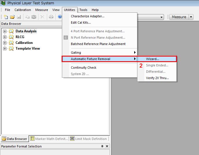
47 8. [Appendix] De-embedding File Creation using PLTS AFR The procedure to create the de-embedding files using the Keysight Physical Layer Test System (PLTS) Automatic Fixture Removal (AFR) function and 2x Thru standard is introduced in the section x Thru Standard Measurement 1. Recall the state file for high speed signal tests as described in Recalling a State File. 2. Press Channel Next to select Channel Press Channel Max to maximize Channel 2 on the screen. 4. Perform the calibration using ECal as described in Frequency-Domain Measurements > 1. ECal Calibration. 5. Connect the E5071C ports (port 1 to 4) to 2x Thru standard with RF cables as shown below (1, 2, 3, 4 are E5071C port numbers). 6. Press Analysis > Fixture Simulator > Topology > Port1 (bal) > Press Analysis > Fixture Simulator > Topology > Port2 (bal) > Press Analysis > Fixture Simulator > Port ZConversion > Port ZConversion and turn OFF. 9. Press Trace Next to select Trace 7 (Sdd21). 10. Press Trace Max to maximize the selected trace on the screen. 11. Press Trigger > Single. 12. Press Save/Recall > Save SnP > S4P > [ ] 13. Enter file name and save the 4-port Touchstone file (*.s4p). 14. Press Analysis > Fixture Simulator > Port ZConversion > Port ZConversion and turn ON. 15. Press Analysis > Fixture Simulator > Topology > Port1 (bal) > Press Analysis > Fixture Simulator > Topology > Port2 (bal) > De-embedding File Creation 1. Launch PLTS software. 2. Click Utilities > Automatic Fixture Removal > Wizard. 47
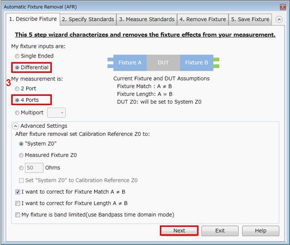
48 3. Select Differential/4-Ports > Next. 4. Check 2X Thru > Next. 48


49 5. Load the Touchstone file for 2x Thru > Next. 6. Click Next. 49


50 7. Select PNA Format > enter file name > Click Save Fixture Files to create two fixture files > Exit. 50
Keysight MOI for USB Type-C Connectors & Cable Assemblies Compliance Tests (Type-C to Legacy Cable Assemblies)
") Revision 01.00 Nov-24, 2015 Universal Serial Bus Type-C TM Specification Revision 1.1 Keysight Method of Implementation (MOI) for USB Type-C TM Connectors and Cables Assemblies Compliance Tests Using Keysight
Revision 01.00 Nov-24, 2015 Universal Serial Bus Type-C TM Specification Revision 1.1 Keysight Method of Implementation (MOI) for USB Type-C TM Connectors and Cables Assemblies Compliance Tests Using Keysight
USB 3.1 Cable-Connector Assembly Compliance Tests. Test Solution Overview Using the Keysight E5071C ENA Option TDR. Last Update 2015/02/06
 USB 3.1 Cable-Connector Assembly s Test Solution Overview Using the Keysight E5071C ENA Option TDR Last Update 015/0/06 Purpose This slide will show how to make measurements of USB 3.1 cable & connector
Agilent MOI for MIPI D-PHY Conformance Tests Revision 1.00 Dec-1, 2011
 Revision 1.00 Dec-1, 2011 Agilent Method of Implementation (MOI) for MIPI D-PHY Conformance Tests Using Agilent E5071C ENA Network Analyzer Option TDR 1 Table of Contents 1. Modification Record... 4 2.
Keysight MOI for MIPI D-PHY Conformance Tests Revision Oct, 2014
 Revision 1.10 10-Oct, 2014 Keysight Method of Implementation (MOI) for MIPI D-PHY Conformance Tests Using Keysight E5071C ENA Network Analyzer Option TDR 1 Table of Contents 1. Modification Record... 4
Agilent MOI for MIPI M-PHY Conformance Tests Revision Mar 2014
 Revision 1.10 20 Mar 2014 Agilent Method of Implementation (MOI) for MIPI M-PHY Conformance Tests Using Agilent E5071C ENA Network Analyzer Option TDR 1 Table of Contents 1. Modification Record... 4 2.
Agilent Technologies High-Definition Multimedia
 Agilent Technologies High-Definition Multimedia Interface (HDMI) Cable Assembly Compliance Test Test Solution Overview Using the Agilent E5071C ENA Option TDR Last Update 013/08/1 (TH) Purpose This slide
Measuring Hot TDR and Eye Diagrams with an Vector Network Analyzer?
 Measuring Hot TDR and Eye Diagrams with an Vector Network Analyzer? Gustaaf Sutorius Application Engineer Agilent Technologies gustaaf_sutorius@agilent.com Page 1 #TDR fit in Typical Digital Development
High Speed Competitive Comparison Report. Samtec MMCX-J-P-H-ST-TH1 Mated With MMCX-P-P-H-ST-TH1 Competitor A (Mated Set) Competitor B (Mated Set)
 Competitor B (Mated Set)") High Speed Competitive Comparison Report Samtec MMCX-J-P-H-ST-TH1 Mated With MMCX-P-P-H-ST-TH1 Competitor A (Mated Set) Competitor B (Mated Set) REVISION DATE: January 6, 2005 TABLE OF CONTENTS Introduction...
High Speed Competitive Comparison Report Samtec MMCX-J-P-H-ST-TH1 Mated With MMCX-P-P-H-ST-TH1 Competitor A (Mated Set) Competitor B (Mated Set) REVISION DATE: January 6, 2005 TABLE OF CONTENTS Introduction...
Advanced Product Design & Test for High-Speed Digital Devices
 Advanced Product Design & Test for High-Speed Digital Devices Presenters Part 1-30 min. Hidekazu Manabe Application Marketing Engineer Agilent Technologies Part 2-20 min. Mike Engbretson Chief Technology
High Speed Characterization Report
 High Speed Characterization Report MMCX-P-P-H-ST-TH1 mated with MMCX-J-P-H-ST-TH1 MMCX-P-P-H-ST-MT1 mated with MMCX-J-P-H-ST-MT1 MMCX-P-P-H-ST-SM1 mated with MMCX-J-P-H-ST-SM1 MMCX-P-P-H-ST-EM1 mated with
Calibration and De-Embedding Techniques in the Frequency Domain
 Calibration and De-Embedding Techniques in the Frequency Domain Tom Dagostino tom@teraspeed.com Alfred P. Neves al@teraspeed.com Page 1 Teraspeed Labs Teraspeed Consulting Group LLC 2008 Teraspeed Consulting
Tektronix Inc. DisplayPort Standard. Revision Tektronix MOI for Cable Tests (DSA8200 based sampling instrument with IConnect software)
") DisplayPort Standard Revision 1.0 05-20-2008 DisplayPort Standard Tektronix MOI for Cable Tests (DSA8200 based sampling instrument with IConnect software) 1 Table of Contents: Modification Records... 4
DisplayPort Standard Revision 1.0 05-20-2008 DisplayPort Standard Tektronix MOI for Cable Tests (DSA8200 based sampling instrument with IConnect software) 1 Table of Contents: Modification Records... 4
High Speed Characterization Report
 HLCD-20-XX-TD-BD-2 Mated with: LSHM-120-XX.X-X-DV-A Description: 0.50 mm Razor Beam High Speed Hermaphroditic Coax Cable Assembly Samtec, Inc. 2005 All Rights Reserved Table of Contents Cable Assembly
High Speed Characterization Report
 SSW-1XX-22-X-D-VS Mates with TSM-1XX-1-X-DV-X Description: Surface Mount Terminal Strip,.1 [2.54mm] Pitch, 13.59mm (.535 ) Stack Height Samtec, Inc. 25 All Rights Reserved Table of Contents Connector Overview...
High Speed Characterization Report
 ESCA-XX-XX-XX.XX-1-3 Mated with: SEAF8-XX-05.0-X-XX-2-K SEAM8-XX-S02.0-X-XX-2-K Description: 0.80 mm SEARAY High-Speed/High-Density Array Cable Assembly, 34 AWG Samtec, Inc. 2005 All Rights Reserved Table
Agilent Correlation between TDR oscilloscope and VNA generated time domain waveform
 Agilent Correlation between TDR oscilloscope and VNA generated time domain waveform Application Note Introduction Time domain analysis (TDA) is a common method for evaluating transmission lines and has
High Speed Characterization Report
 ERCD_020_XX_TTR_TED_1_D Mated with: ERF8-020-05.0-S-DV-L Description: 0.8mm Edge Rate High Speed Coax Cable Assembly Samtec, Inc. 2005 All Rights Reserved Table of Contents Cable Assembly Overview... 1
High Speed Characterization Report
 ECDP-16-XX-L1-L2-2-2 Mated with: HSEC8-125-XX-XX-DV-X-XX Description: High-Speed 85Ω Differential Edge Card Cable Assembly, 30 AWG ACCELERATE TM Twinax Cable Samtec, Inc. 2005 All Rights Reserved Table
High Speed Characterization Report
 PCRF-064-XXXX-EC-SMA-P-1 Mated with: PCIE-XXX-02-X-D-TH Description: PCI Express Cable Assembly, Low Loss Microwave Cable Samtec, Inc. 2005 All Rights Reserved Table of Contents Cable Assembly Overview...
High Speed Characterization Report
 QTH-030-01-L-D-A Mates with QSH-030-01-L-D-A Description: High Speed Ground Plane Header Board-to-Board, 0.5mm (.0197 ) Pitch, 5mm (.1969 ) Stack Height Samtec, Inc. 2005 All Rights Reserved Table of Contents
High Speed Characterization Report
 PCIEC-XXX-XXXX-EC-EM-P Mated with: PCIE-XXX-02-X-D-TH Description: 1.00 mm PCI Express Internal Cable Assembly, 30 AWG Twinax Ribbon Cable Samtec, Inc. 2005 All Rights Reserved Table of Contents Cable
Signal Integrity Tips and Techniques Using TDR, VNA and Modeling. Russ Kramer O.J. Danzy
 Signal Integrity Tips and Techniques Using TDR, VNA and Modeling Russ Kramer O.J. Danzy Simulation What is the Signal Integrity Challenge? Tx Rx Channel Asfiakhan Dreamstime.com - 3d People Communication
High Speed Characterization Report
 PCRF-064-1000-SMA-P-1 Mated with: PCIE-XXX-02-X-D-TH and SMA-J-P-X-ST-TH1 Description: Cable Assembly, Low Loss Microwave Coax, PCI Express Breakout Samtec, Inc. 2005 All Rights Reserved Table of Contents
High Data Rate Characterization Report
 High Data Rate Characterization Report EQCD-020-39.37-STR-TTL-1 EQCD-020-39.37-STR-TEU-2 Mated with: QTE-020-01-X-D-A and QSE-020-01-X-D-A Description: 0.8mm High-Speed Coax Cable Assembly Samtec, Inc.
High Speed Characterization Report
 HDLSP-035-2.00 Mated with: HDI6-035-01-RA-TR/HDC-035-01 Description: High Density/High Speed IO Cable Assembly Samtec, Inc. 2005 All Rights Reserved Table of Contents Introduction...1 Product Description...1
High Data Rate Characterization Report
 High Data Rate Characterization Report EQRF-020-1000-T-L-SMA-P-1 Mated with: QSE-xxx-01-x-D-A and SMA-J-P-x-ST-TH1 Description: Cable Assembly, High Speed Coax, 0.8 mm Pitch Samtec, Inc. 2005 All Rights
High Speed Characterization Report
 TCDL2-10-T-05.00-DP and TCDL2-10-T-10.00-DP Mated with: TMMH-110-04-X-DV and CLT-110-02-X-D Description: 2-mm Pitch Micro Flex Data Link Samtec, Inc. 2005 All Rights Reserved Table of Contents Introduction...1
Electronic Calibration (ECal) Modules for Vector Network Analyzers
 Modules for Vector Network Analyzers") TECHNICAL OVERVIEW Electronic Calibration (ECal) Modules for Vector Network Analyzers N755xA Series, 2-port Economy ECal Module 8509xC Series, 2-port RF ECal Module N469xD Series, 2-port Microwave ECal
TECHNICAL OVERVIEW Electronic Calibration (ECal) Modules for Vector Network Analyzers N755xA Series, 2-port Economy ECal Module 8509xC Series, 2-port RF ECal Module N469xD Series, 2-port Microwave ECal
High Data Rate Characterization Report
 High Data Rate Characterization Report VPSTP-016-1000-01 Mated with: VRDPC-50-01-M-RA and VRDPC-50-01-M-RA Description: Plug Shielded Twisted Pair Cable Assembly, 0.8mm Pitch Samtec, Inc. 2005 All Rights
June 2012 Agilent Technologies
 Perform Cable Test with a Network Analyzer: From Basic Measurement to Advanced Signal Integrity Measurements for Next Generation High Speed Serial Standards June 2012 Agilent Technologies Agenda 1. Device
Keysight Technologies Using the Time-Domain Reflectometer. Application Note S-Parameter Series
 Keysight Technologies Using the Time-Domain Reflectometer Application Note S-Parameter Series 02 Keysight S-parameter Series: Using the Time-Domain Reflectometer - Application Note Analysis of High-Speed
RF Characterization Report
 SMA-J-P-H-ST-MT1 Mated with: RF316-01SP1-01BJ1-0305 Description: 50-Ω SMA Board Mount Jack, Mixed Technology Samtec, Inc. 2005 All Rights Reserved Table of Contents Introduction...1 Product Description...1
Agilent 4-Port PNA-L Network Analyzers
 Agilent 4-Port PNA-L Network Analyzers N5230A Options 240, 245 300 khz to 20 GHz Speed and accuracy you can count on Integrated 4-port, balanced measurements up to 20 GHz Introducing the 4-port PNA-L network
High Data Rate Characterization Report
 High Data Rate Characterization Report ERDP-013-39.37-TTR-STL-1-D Mated with: ERF8-013-05.0-S-DV-DL-L and ERM8-013-05.0-S-DV-DS-L Description: Edge Rate Twin-Ax Cable Assembly, 0.8mm Pitch Samtec, Inc.
Network Analysis Seminar. Cables measurement
 Network Analysis Seminar Cables measurement Agenda 1. Device Under Test: Cables & Connectors 2. Instrument for cables testing: Network Analyzer 3. Measurement: Frequency Domain 4. Measurement: Time Domain
Keysight Technologies PNA Microwave Network Analyzers
 Keysight Technologies PNA Microwave Network Analyzers Application Note Banded Millimeter-Wave Measurements with the PNA 02 Keysight PNA Microwave Network Analyzers Application Note Table of Contents Introduction...
Serial ATA International Organization
 Serial ATA International Organization Version 1.0 May 29, 2008 Serial ATA Interoperability Program Revision 1.3 Tektronix MOI for Rx/Tx Tests (DSA/CSA8200 based sampling instrument with IConnect SW) This
SPICE Model Validation Report
 HFEM-SE High Speed Flex Data Link Mated with: QTE-xxx-01-x-D-A QSE-xxx-01-x-D-A Description: Flex Data Link, High Speed, 0.8mm Pitch New Albany IN 47151-1147 USA SIG@samtec.com Report Revision: 9/13/2007
VHDM & VHDM-L Series. High Speed. Electrical Characterization
 VHDM & VHDM-L Series High Speed Electrical Characterization HDM, VHDM & VHDM-HSD are trademarks or registered trademarks of Teradyne, Inc. Date: 2/14/2003 SCOPE 1. The scope of this document is to define
SPARQ Signal Integrity Network Analyzer. High-bandwidth, Multi-port S-parameters
 SPARQ Signal Integrity Network Analyzer High-bandwidth, Multi-port S-parameters SPARQ: S-Parameters SPARQ: S-Parameters Quick Quick Key Features Provides S-parameter measurements up to four-ports measures
High Speed Characterization Report
 High Speed Characterization Report HDR-108449-01-HHSC HDR-108449-02-HHSC HDR-108449-03-HHSC HDR-108449-04-HHSC FILE: HDR108449-01-04-HHSC.pdf DATE: 03-29-04 Table of Contents Introduction. 1 Product Description.
Limitations And Accuracies Of Time And Frequency Domain Analysis Of Physical Layer Devices
 Limitations And Accuracies Of Time And Frequency Domain Analysis Of Physical Layer Devices Outline Short Overview Fundamental Differences between TDR & Instruments Calibration & Normalization Measurement
Configuration of PNA-X, NVNA and X parameters
 Configuration of PNA-X, NVNA and X parameters VNA 1. S-Parameter Measurements 2. Harmonic Measurements NVNA 3. X-Parameter Measurements Introducing the PNA-X 50 GHz 43.5 GHz 26.5 GHz 13.5 GHz PNA-X Agilent
VVM measurement with E5061B for replacing 8508A vector voltmeter. May 2013 Agilent Technologies
 VVM measurement with E5061B for replacing 8508A vector voltmeter May 2013 Agilent Technologies Overview of VVM measurement with E5061B Application discussed here Measuring the phase difference (& magnitude
Bill Ham Martin Ogbuokiri. This clause specifies the electrical performance requirements for shielded and unshielded cables.
 098-219r2 Prepared by: Ed Armstrong Zane Daggett Bill Ham Martin Ogbuokiri Date: 07-24-98 Revised: 09-29-98 Revised again: 10-14-98 Revised again: 12-2-98 Revised again: 01-18-99 1. REQUIREMENTS FOR SPI-3
Test ID 5-15 Utility Line Impedance Test Procedures Guide
 Test ID 5-15 Utility Line Impedance Test Procedures Guide Revision 1.1 Tektronix October 13, 2010 Page 2 of 18 Equipment Required Table 1 lists the equipment required to perform the Utility Line Impedance
The Practical Limitations of S Parameter Measurements and the Impact on Time- Domain Simulations of High Speed Interconnects
 The Practical Limitations of S Parameter Measurements and the Impact on Time- Domain Simulations of High Speed Interconnects Dennis Poulin Anritsu Company Slide 1 Outline PSU Signal Integrity Symposium
Custom Interconnects Fuzz Button with Hardhat Test Socket/Interposer 1.00 mm pitch
 Custom Interconnects Fuzz Button with Hardhat Test Socket/Interposer 1.00 mm pitch Measurement and Model Results prepared by Gert Hohenwarter 12/14/2015 1 Table of Contents TABLE OF CONTENTS...2 OBJECTIVE...
High Speed Characterization Report
 LSHM-150-06.0-L-DV-A Mates with LSHM-150-06.0-L-DV-A Description: High Speed Hermaphroditic Strip Vertical Surface Mount, 0.5mm (.0197") Centerline, 12.0mm Board-to-Board Stack Height Samtec, Inc. 2005
Demo / Application Guide for DSA815(-TG) / DSA1000 Series
 / DSA1000 Series") Demo / Application Guide for DSA815(-TG) / DSA1000 Series TX1000 Mobile Phone Frontend Mixer Bandpass Filter PA The schematic above shows a typical front end of a mobile phone. Our TX1000 RF Demo Kit shows
Demo / Application Guide for DSA815(-TG) / DSA1000 Series TX1000 Mobile Phone Frontend Mixer Bandpass Filter PA The schematic above shows a typical front end of a mobile phone. Our TX1000 RF Demo Kit shows
Keysight Technologies E5071C ENA Vector Network Analyzer. E5092A Configurable Multiport Test Set
 Keysight Technologies E5071C ENA Vector Network Analyzer 9 khz to 4.5/6.5/8.5 GHz 100 khz to 4.5/6.5/8.5 GHz (with bias tees) 300 khz to 14/20 GHz (with bias tees) E5092A Configurable Multiport Test Set
Challenges and Solutions for Removing Fixture Effects in Multi-port Measurements
 DesignCon 2008 Challenges and Solutions for Removing Fixture Effects in Multi-port Measurements Robert Schaefer, Agilent Technologies schaefer-public@agilent.com Abstract As data rates continue to rise
Keysight 2-Port and 4-Port PNA-X Network Analyzer
 Keysight 2-Port and 4-Port PNA-X Network Analyzer N5249A - 0 MHz to 8.5 GHz N524A - 0 MHz to 3.5 GHz N5242A - 0 MHz to 26.5 GHz Data Sheet and Technical Specifications Documentation Warranty THE MATERIAL
Keysight Technologies In-Fixture Measurements Using Vector Network Analyzers. Application Note
 Keysight Technologies In-Fixture Measurements Using Vector Network Analyzers Application Note Introduction This application note describes the use of vector network analyzers when making measurements of
PNA Family Microwave Network Analyzers (N522x/3x/4xB) CONFIGURATION GUIDE
 CONFIGURATION GUIDE") PNA Family Microwave Network Analyzers (N522x/3x/4xB) CONFIGURATION GUIDE Table of Contents PNA Family Network Analyzer Configurations... 05 Test set and power configuration options...05 Hardware options...
PNA Family Microwave Network Analyzers (N522x/3x/4xB) CONFIGURATION GUIDE Table of Contents PNA Family Network Analyzer Configurations... 05 Test set and power configuration options...05 Hardware options...
External Source Control
 External Source Control X-Series Signal Analyzers Option ESC DEMO GUIDE Introduction External source control for X-Series signal analyzers (Option ESC) allows the Keysight PXA, MXA, EXA, and CXA to control
Compact Series: S5065 & S5085 Vector Network Analyzers KEY FEATURES
 Compact Series: S5065 & S5085 Vector Network Analyzers KEY FEATURES Frequency range: 9 khz - 6.5 or 8.5 GHz Measured parameters: S11, S12, S21, S22 Wide output power adjustment range: -50 dbm to +5 dbm
Aries Kapton CSP socket
 Aries Kapton CSP socket Measurement and Model Results prepared by Gert Hohenwarter 5/19/04 1 Table of Contents Table of Contents... 2 OBJECTIVE... 3 METHODOLOGY... 3 Test procedures... 4 Setup... 4 MEASUREMENTS...
Platform Migration 8510 to PNA. Graham Payne Application Engineer Agilent Technologies
 Platform Migration 8510 to PNA Graham Payne Application Engineer Agilent Technologies We set the standard... 8410 8510 When we introduced the 8510, we changed the way S-parameter measurements were made!
Advanced Measurement Techniques for RF Amplifiers Using Unique Functions of the Agilent E5071C ENA. Application Note
 Advanced Measurement Techniques for RF Amplifiers Using Unique Functions of the Agilent E5071C ENA Application Note Introduction The RF amplifier is a key component used in a wide variety of industries
Agilent. E5071C ENA Network Analyzer 9 khz to 4.5/6.5/8.5 GHz 100 khz to 4.5/6.5/8.5 GHz (with bias tees) 300 khz to 14/20 GHz (with bias tees)
 300 khz to 14/20 GHz (with bias tees)") Agilent E5071C ENA Network Analyzer 9 khz to 4.5/6.5/8.5 GHz 0 khz to 4.5/6.5/8.5 GHz (with bias tees) 300 khz to 14/20 GHz (with bias tees) E5091A Multiport Test Set E5092A Configurable Multiport Test
Agilent E5071C ENA Network Analyzer 9 khz to 4.5/6.5/8.5 GHz 0 khz to 4.5/6.5/8.5 GHz (with bias tees) 300 khz to 14/20 GHz (with bias tees) E5091A Multiport Test Set E5092A Configurable Multiport Test
Faculty of Electrical & Electronics Engineering BEE4233 Antenna and Propagation. LAB 1: Introduction to Antenna Measurement
 Faculty of Electrical & Electronics Engineering BEE4233 Antenna and Propagation LAB 1: Introduction to Antenna Measurement Mapping CO, PO, Domain, KI : CO2,PO3,P5,CTPS5 CO1: Characterize the fundamentals
Fast network analyzers also for balanced measurements
 GENERAL PURPOSE Network analyzers 44297/5 FIG 1 The new Vector Network Analyzer R&S ZVB, here with four-port configuration. Vector Network Analyzers R&S ZVB Fast network analyzers also for balanced measurements
PLANAR R54. Vector Reflectometer KEY FEATURES
 PLANAR R54 Vector Reflectometer KEY FEATURES Frequency range: 85 MHz 5.4 GHz Reflection coefficient magnitude and phase, cable loss, DTF Transmission coefficient magnitude when using two reflectometers
Advanced Test Equipment Rentals ATEC (2832)
") Established 1981 Advanced Test Equipment Rentals www.atecorp.com 800-404-ATEC (2832) Agilent 2-Port and 4-Port PNA-X Network Analyzer N5249A - 10 MHz to 8.5 GHz N5241A - 10 MHz to 13.5 GHz N5242A - 10
Established 1981 Advanced Test Equipment Rentals www.atecorp.com 800-404-ATEC (2832) Agilent 2-Port and 4-Port PNA-X Network Analyzer N5249A - 10 MHz to 8.5 GHz N5241A - 10 MHz to 13.5 GHz N5242A - 10
High Speed Characterization Report
 FTSH-115-03-L-DV-A Mated With CLP-115-02-L-D-A Description: Parallel Board-to-Board, 0.050 [1.27mm] Pitch, 5.13mm (0.202 ) Stack Height Samtec, Inc. 2005 All Rights Reserved Table of Contents Connector
NATIONAL UNIVERSITY of SINGAPORE
 NATIONAL UNIVERSITY of SINGAPORE Faculty of Engineering Electrical & Computer Engineering Department EE3104 Introduction to RF and Microwave Systems & Circuits Experiment 1 Familiarization on VNA Calibration
PXIe Contents CALIBRATION PROCEDURE
 CALIBRATION PROCEDURE PXIe-5632 This document contains the verification and adjustment procedures for the PXIe-5632 Vector Network Analyzer. Refer to ni.com/calibration for more information about calibration
Introducing ENA Series E5061B-1x5/2x5/1x7/2x7 RF NA Options 100 khz to 1.5 / 3 GHz
 Introducing ENA Series E5061B-1x5/2x5/1x7/2x7 RF NA Options 100 khz to 1.5 / 3 GHz Suitable for manufacturing The successor for E5061A/62A RF NA options* E5061B-115, 215, 135, 235: 50 Ω E5061B-117, 217,
High Speed Characterization Report
 MEC1-150-02-L-D-RA1 Description: Mini Edge-Card Socket Right Angle Surface Mount, 1.0mm (.03937 ) Pitch Samtec, Inc. 2005 All Rights Reserved Table of Contents Connector Overview... 1 Connector System
Compact Series: S5048 & TR5048 Vector Network Analyzers KEY FEATURES
 Compact Series: S5048 & TR5048 Vector Network Analyzers KEY FEATURES Frequency range: 20 khz - 4.8 GHz Measured parameters: S11, S12, S21, S22 (S5048) S11, S21 (TR5048) Wide output power adjustment range:
Overcome mmwave Component Test Challenges. Senior Project Manager / Keysight Technologies
 Overcome mmwave Component Test Challenges Senior Project Manager / Keysight Technologies Kenny Liao 2018.06.11 Taipei D I S C U S S I O N T O P I C S Millimeter Wave Component Application Space Millimeter
Impedance 50 (75 connectors via adapters)
") VECTOR NETWORK ANALYZER PLANAR 304/1 DATA SHEET Frequency range: 300 khz to 3.2 GHz Measured parameters: S11, S21, S12, S22 Dynamic range of transmission measurement magnitude: 135 db Measurement time
VECTOR NETWORK ANALYZER PLANAR 304/1 DATA SHEET Frequency range: 300 khz to 3.2 GHz Measured parameters: S11, S21, S12, S22 Dynamic range of transmission measurement magnitude: 135 db Measurement time
Reflectometer Series:
 Reflectometer Series: R54, R60 & R140 Vector Network Analyzers Clarke & Severn Electronics Ph +612 9482 1944 Email sales@clarke.com.au BUY NOW - www.cseonline.com.au KEY FEATURES Patent: US 9,291,657 No
application In-Fixture Measurements Using Vector Network Analyzers Network Analysis Solutions Application Note
 application Network Analysis Solutions In-Fixture Measurements Using Vector Network Analyzers Application Note 1287-9 Table of contents Introduction..................................................3 The
RF Characterization Report
 RF178 Series Cable Assemblies RF178-2SJ1-2SJ1-35 RF178-2RP1-2RP1-35 RF178-2SP1-2SP1-36 RF178-3RP1-3RP1-36 RF178-S7RP4-S7RP4-35 RF178-S7SP4-S7SP4-35 Description: RF Cable Assembly, 5 Ohm, RG178 Cable Samtec
Advanced Signal Integrity Measurements of High- Speed Differential Channels
 Advanced Signal Integrity Measurements of High- Speed Differential Channels September 2004 presented by: Mike Resso Greg LeCheminant Copyright 2004 Agilent Technologies, Inc. What We Will Discuss Today
Keysight Technologies FieldFox Handheld Analyzers
 Keysight Technologies FieldFox Handheld Analyzers 4/6.5/9/14/18/26.5/32/44/50 GHz Data Sheet N9913A N9914A N9915A N9925A N9935A N9916A N9926A N9936A N9917A N9927A N9937A N9918A N9928A N9938A N9950A N9951A
Signal Generators for Anritsu RF and Microwave Handheld Instruments
 Measurement Guide Signal Generators for Anritsu RF and Microwave Handheld Instruments BTS Master Spectrum Master Tracking Generator Option 20 Vector signal Generator Option 23 Anritsu Company 490 Jarvis
Keysight Technologies Signal Integrity Tips and Techniques Using TDR, VNA and Modeling
 Keysight Technologies Signal Integrity Tips and Techniques Using, VNA and Modeling Article Reprint This article first appeared in the March 216 edition of Microwave Journal. Reprinted with kind permission
Keysight E5063A ENA Vector Network Analyzer. 100 khz to 500 M/1.5 G/3 G/4.5 G/6.5 G/8.5 G/14 G/18 GHz
 Keysight E5063A ENA Vector Network Analyzer 100 khz to 500 M/1.5 G/3 G/4.5 G/6.5 G/8.5 G/14 G/18 GHz 02 Keysight E5063A ENA Vector Network Analyzer - Brochure The Best Balance Between Price and Performance
Procedures Guide. Tektronix. HDMI Sink Instruments Differential Impedance Measurement
 Procedures Guide Tektronix HDMI Sink Instruments Differential Impedance Measurement Equipment Required Table 1: Equipment required Table 1 lists the equipment required to perform the differential impedance
High Speed Characterization Report
 TMMH-115-05-L-DV-A Mated With CLT-115-02-L-D-A Description: Micro Surface Mount, Board-to Board, 2.0mm (.0787 ) Pitch, 4.77mm (0.188 ) Stack Height Samtec, Inc. 2005 All Rights Reserved Table of Contents
ME1000 RF Circuit Design. Lab 4. Filter Characterization using Vector Network Analyzer (VNA)
") ME1000 RF Circuit Design Lab 4 Filter Characterization using Vector Network Analyzer (VNA) This courseware product contains scholarly and technical information and is protected by copyright laws and international
ME1000 RF Circuit Design Lab 4 Filter Characterization using Vector Network Analyzer (VNA) This courseware product contains scholarly and technical information and is protected by copyright laws and international
Aries QFP microstrip socket
 Aries QFP microstrip socket Measurement and Model Results prepared by Gert Hohenwarter 2/18/05 1 Table of Contents Table of Contents... 2 OBJECTIVE... 3 METHODOLOGY... 3 Test procedures... 4 Setup... 4
Amphenol Amphenol Taiwan Corporation Sheet 1 of 14
 Amphenol Amphenol Taiwan Corporation Sheet 1 of 14 Title: Part Number: Description: USB3.0 Connector Product Specification GSB34 / GSB35 series Micro Family, Receptacle, SMT, PCB mount Revisions Control
E5071C ENA Vector Network Analyzer. E5092A Configurable Multiport Test Set
 DATA SHEET E5071C ENA Vector Network Analyzer 9 khz to 4.5/6.5/8.5 GHz 100 khz to 4.5/6.5/8.5 GHz (with bias tees) 300 khz to 14/20 GHz (with bias tees) E5092A Configurable Multiport Test Set Table of
S-Parameter Measurements with the Bode 100
 Page 1 of 10 with the Bode 100 Page 2 of 10 Table of Contents 1 S-Parameters...3 2 S-Parameter Measurement with the Bode 100...4 2.1 Device Setup...4 2.2 Calibration...5 2.3 Measurement...7 2.3.1 S11 and
IMD Measurement Wizard for the E5072A ENA Series Network Analyzer Operation Manual. Agilent Technologies June 2012
 IMD Measurement Wizard for the E5072A ENA Series Network Analyzer Operation Manual Agilent Technologies June 2012 1 Important Notice Notices The information contained in this document is subject to change
Agilent AN Applying Error Correction to Network Analyzer Measurements
 Agilent AN 287-3 Applying Error Correction to Network Analyzer Measurements Application Note 2 3 4 4 5 6 7 8 0 2 2 3 3 4 Table of Contents Introduction Sources and Types of Errors Types of Error Correction
PLANAR S5048 and TR5048
 PLANAR S5048 and TR5048 Vector Network Analyzers KEY FEATURES Frequency range: 20 khz 4.8 GHz COM/DCOM compatible for LabView Measured parameters: and automation programming S11, S12, S21, S22 (S5048)
Agilent. E5071C ENA Network Analyzer 9 khz to 4.5/6.5/8.5 GHz 100 khz to 4.5/6.5/8.5 GHz (with bias tees) 300 khz to 14/20 GHz (with bias tees)
 300 khz to 14/20 GHz (with bias tees)") Agilent E571C ENA Network Analyzer 9 khz to 4.5/6.5/8.5 GHz khz to 4.5/6.5/8.5 GHz (with bias tees) 3 khz to 14/2 GHz (with bias tees) E592A Configurable Multiport Test Set Data Sheet Table of Contents
Agilent E571C ENA Network Analyzer 9 khz to 4.5/6.5/8.5 GHz khz to 4.5/6.5/8.5 GHz (with bias tees) 3 khz to 14/2 GHz (with bias tees) E592A Configurable Multiport Test Set Data Sheet Table of Contents
Product Overview: Main Features: AV3672A/B/C -S Vector Network Analyzer. (10MHz~13.5 GHz/26.5 GHz/43.5 GHz)
") AV3672A/B/C -S Vector Network Analyzer (10MHz~13.5 GHz/26.5 GHz/43.5 GHz) Product Overview: AV3672*-S series vector network analyzer is consist of AV3672A-S(10MHz~13.5GHz), AV3672B-S(10MHz~26.5GHz)and
AV3672A/B/C -S Vector Network Analyzer (10MHz~13.5 GHz/26.5 GHz/43.5 GHz) Product Overview: AV3672*-S series vector network analyzer is consist of AV3672A-S(10MHz~13.5GHz), AV3672B-S(10MHz~26.5GHz)and
MIPI S-parameter & Impedance Measurements with ENA Option TDR. Last update: 2014/04/08 (HK)
") MIPI S-parameter & Impedance Measurements with ENA Option TDR Last update: 2014/04/08 (HK) 1 MIPI Interfaces in a Mobile Platform 2 MIPI High Speed Physical, Protocol & App Layer Application Protocol Standard
MIPI S-parameter & Impedance Measurements with ENA Option TDR Last update: 2014/04/08 (HK) 1 MIPI Interfaces in a Mobile Platform 2 MIPI High Speed Physical, Protocol & App Layer Application Protocol Standard
EE290C - Spring 2004 Advanced Topics in Circuit Design
 EE290C - Spring 2004 Advanced Topics in Circuit Design Lecture #3 Measurements with VNA and TDR Ben Chia Tu-Th 4 5:30pm 531 Cory Agenda Relationships between time domain and frequency domain TDR Time Domain
Keysight Technologies FieldFox Handheld Analyzers
 Keysight Technologies FieldFox Handheld Analyzers 4/6.5/9/14/18/26.5/32/44/50 GHz Data Sheet N9913A N9914A N9915A N9925A N9935A N9916A N9926A N9936A N9917A N9927A N9937A N9918A N9928A N9938A N9950A N9951A
AV3672 Series Vector Network Analyzer
 AV3672 Series Vector Network Analyzer AV3672A/B/C/D/E (10MHz 13.5 GHz/26.5 GHz/43.5 GHz/50 GHz/67 GHz) Product Overview: AV3672 series vector network analyzer include AV3672A (10MHz 13.5GHz), AV3672B (10MHz
Agilent 2-Port and 4-Port PNA-X Network Analyzer. N5241A - 10 MHz to 13.5 GHz N5242A - 10 MHz to 26.5 GHz Data Sheet and Technical Specifications
 Agilent 2-Port and 4-Port PNA-X Network Analyzer N5241A - 10 MHz to 13.5 GHz N5242A - 10 MHz to 26.5 GHz Data Sheet and Technical Specifications Documentation Warranty THE MATERIAL CONTAINED IN THIS DOCUMENT
Agilent Accurate Measurement of Packaged RF Devices. White Paper
 Agilent Accurate Measurement of Packaged RF Devices White Paper Slide #1 Slide #2 Accurate Measurement of Packaged RF Devices How to Measure These Devices RF and MW Device Test Seminar 1995 smafilt.tif
10G Ethernet Compliance Software Instruction Manual. QPHY-10GBase-T
 10G Ethernet Compliance Software Instruction Manual QPHY-10GBase-T (Tx and RL Tests) Revision B November, 2017 Relating to: XStreamDSO v8.5.x.x QualiPHY Software v.8.5.x.x 700 Chestnut Ridge Road Chestnut