3. Electromagnetic methods 3.1 Introduction
|
|
|
- Cecil Nicholson
- 6 years ago
- Views:
Transcription
1 3. Electromagnetic methods 3.1 Introduction The electromagnetic techniques have the broadest range of different instrumental systems. They can be classified as either time domain (TEM) of frequency domain (FEM) systems. FEM: use one or more frequencies TEM: Measurements as a function of time 1
2 Active and passive methods EM methods can be either passive, utilizing natural ground signals (e.g. magnetotellurics) or active, where an artificial transmitter is used either in the near field (as in ground conductivity meters) or in the far field (using remote high powered military and civil radio transmitters as in the case of VLF and RMT methods). The aim of the measurements is the same as in DC geoelectrics. 2
3 Determination of resistivity Fig. 2 Fig. 1 Determination of resistivity as a function of depth or a function of profile distance. 3
4 Advantage of EM methods The main advantage of the EM methods is that they do not require direct contact with the ground as in the case of DC electrical methods. Therefore the EM measurements can be carried out in a faster way than the DC measurements. The range of EM applications is large. It is dependent upon the type of equipment but can be categorized as listed in the table. 4
5 Table: The range of applications for EM surveying (independent of instrument type) ¹ Mineral exploration Mineral resource evaluation Groundwater surveys Mapping contaminant plumes Geothermal resource investigations Contaminated land mapping Landfill surveys Detection of geological and artificial cavities Location of geological faults, etc. Geological mapping Permafrost mapping, etc. 5
6 3.2 Principles of EM surveying Electromagnetic (EM) methods make use of the response of the ground to the propagation of the electromagnetic fields which are composed of alternating electric intensity and magnetic force. An electromagnetic field may be defined in terms of four vector functions E, D, H and B, where: E is the electrical field in V/m. D is the dielectric displacement in Coulomb/m². H is the magnetic field intensity in A/m. B is the magnetic induction in Tesla. 6
7 Maxwell' s equations: Faraday' s law Experimental evidence shows that all electro magnetic phenomena obey the following four Maxwell equations. (3.1) rot E= B/ t Fig. 3: Electric field generated by a time varying magnetic field. Faraday' s law. It shows us how a time varying magnetic field produces an electrical voltage. 7
8 Maxwell' s equations: Ampere' s law rot H= J D/ t (3.2) Ampere' s law. It shows us how an electric current and/or a time varying electric field generates a magnetic field. Fig. 4: Magnetic field generated by a time varying electric field. 8
9 Maxwell' s Equations div B=0 (3.3) It infers that lines of magnetic induction are continuous and there are no single magnetic poles. div D=q (3.4) It infers that electrical fields can begin and end on electrical charges. 9
10 Subsidiary equations and wave equation By using the following subsidiary equations, D= E B= H J= E where J = electrical current density in A/m² q = electric charge in Coulomb/m³ = electrical permittivitiy = magnetic permeability = electrical conductivity and the four Maxwell equations the electro magnetic wave equation can be derived. Such waves, with low attenuation and their relationship are shown in the following figure. 10
11 Fig. 5: The electric and magnetic vectors in an electromagnetic wave are perpendicular to each other and to the direction of propagation x. 11
12 EM waves and Geophysics An electromagnetic field can be generated by passing an alternating current through a small core made up of many turns of wire or through a large loop of wire. For geophysical applications, frequencies of the primary alternating field are usually less than a few thousand Hertz. The wavelength of the primary wave is of the order of km, while the source receiver separation is much smaller. The propagation of the primary wave and associated wave attenuation can be disregarded. 12
13 Fig. 6: The physical separation of a transmitter (Tx) and a receiver is very small in relation to the wavelength of the EM waves with frequencies greater than 3 khz. Consequently, attenuation due to wave propagation can be ignored. ¹ 13
14 A transmitter coil can be used to generate the primary electromagnetic field which propagates above and below the ground. Fig. 7: General principle of electro magnetic surveying. ² 14
15 Primary and secondary fields Where the subsurface is homogeneous there is no difference between the fields propagated above the surface and through the ground (only slight reduction in amplitude). If a conductive anomaly is present, the magnetic component of the incident EM wave induces alternating currents (Eddy currents) within the conductor. The eddy currents generate their own secondary EM field which travels to the receiver. 15
16 Primary and secondary fields The receiver also detects the primary field which travels through the air. The receiver responds then to the resultant of the arriving primary and secondary fields. Consequently, the measured response will differ in both phase and amplitude relative to the unmodulated primary field. These differences between the transmitted and received electromagnetic fields reveal the presence of the conductor and provide information on its geometry and electrical properties. 16
17 3.3 Depth of penetration of electromagnetic fields The depth of penetration of an electromagnetic field depends upon its FREQUENCY and the ELECTRICAL CONDUCTIVITY of the medium. The amplitude of EM fields decreases exponentially with depth. The amplitude of EM radiation as a function of depth relative to its original amplitude A0 is given by 1 A d =A 0 e. The depth of penetration can be defined as the depth at which the amplitude Ad is decreased by the factor e 1 compared with its surface amplitude. Penetration depth d is given by d [ m]=503 [ m]/f [Hz]. 17
18 Example: Depth of penetration f =10 m f =10 Hz d=503 m f =100 Hz d=159 m f =1000 Hz d=50.3 m 18
19 3.4 Principle of Slingram method Fig. 8³ 19
20 Principle of Slingram method Ip(t) creates a magnetic field Bp(t) Up(t): induced voltage in receiver (law of induction) eddy currents Ib(t) in the ground magnetic field Bb(t) (dependent on (law of induction) conductivity Us(t): induced voltage in receiver distribution in 20 the ground)
21 3.4.1 Signal decomposition Induced currents and the associated secondary magnetic fields differ in phase from the primary field, and detected signals can therefore be resolved into components which are in phase and 90 out of phase with the primary field. In phase components sometimes termed as real, as opposed to imaginary, quadrature or simply out of phase. 21
 current in the receiver I t =I 0 sin t 0 coil (recorded signal) out phase (90 phase)")
22 Fig. 9: Signal decompo sition for EM measure ments.³ current in the transmitter I t =I sin t 1 0 coil (induced signal) current in the receiver I t =I 0 sin t 0 coil (recorded signal) out phase (90 phase) signal Iout t ( imaginary part, Im) Iin t in phase (0 phase) signal ( real part, Re) =Iin t Iout t 22
23 Signal decomposition measured signal at receiver: U s t U p t can b e eliminated result: amplitude of the 0 phase and 90 phase of Us(t) phase shift of Us(t) relative to Up(t) 23
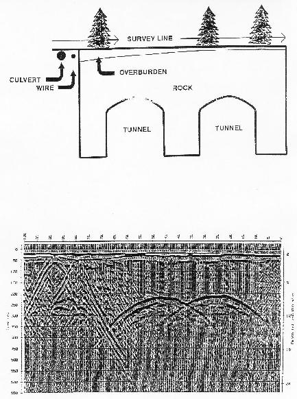
24 Fig. 10: Explanation of Slingram anomaly ³ 24
25 3.4.2 The Slingram anomaly No anomaly is detected by a horizontal receiving coil immediately above the body because the secondary field there is horizontal. Similarly there will be zero anomaly when the transmitter coil is vertical above the body because no significant eddy currents will be induced. The greatest (negative) secondary field values will be observed when the conductor lies mid way between the two coils. 25
26 3.4.3 Airborne Systems Fig. 11: Principle of airborne electromagnetic surveying. The system shown deployed is of the towed bird type.¹ 26

 Cessna 404 fixed wing aircraft with a total field magneto meter")
27 (B) Fig. 12: (A) Eurocopter AS350B towing three instrument pods. They are from the top 2 channel VLF EM, total field cesium magnetometer, and a 5 frequency electromagnetic induction system. (B) Cessna 404 fixed wing aircraft with a total field magneto meter mounted in a tail stinger.¹ (A) 27
28 3.4.4 Case histories Fig. 13: Mapping using electromagnetic induction. 4 28
29 Fig. 14: EMAC 36 results and geological section, Modipane, Botswana. 29
30 3.4.5 Ground conductivity meters (measurements at low induction number) The instruments (manufactured by Geonics Ltd.) provides a direct reading of the quadrature as the apparent conductivity in ms/m. The secondary EM field measured in a mobile transmitter receiver system is generally a complex function of the coil spacing s, the operating frequency Fig. 15: Moving dual coil EM system; circles indicate the f and conductivity of the transmitter (Tx) and subsurface. 30 receiver (Rx) coils.¹
31 Ground conductivity meters The ratio of the intercoil spacing (s) divided by the skin depth is known as the induction number B. Where the induction number is less than one, then the ration of the secondary to the primary of magnetic fields at the receiver is directly proportional to apparent conductivity. The ratio of the secondary (Hs) to primary (Hp) magnetic fields at the receiver at low induction numbers (B<<1) is given by 2 H s /H p =i 0 s /4 31
32 Ground conductivity meters The measuring system is designed to ensure that with the selected frequency f, for a given inter coil separation (s), a designed response of Hp for a given transmitter, the only unknowns Hs which is measured by the instrument 2 a = 4/ 0 s H s /H p q where the subscript q denotes the quadrature phase. 32

33 Two devices: EM31 and EM 34 3 EM 31: 3.7 m coil spacing f=9.8 khz EM 34 3: 10 m coil spacing f=6.4 khz 20 m coil spacing f=1.6 khz 30 m coil spacing f=0.4 khz Fig
34 Case histories Electromagnetic mapping sand body Fig. 17: Mapping lateral changes of the near surface geology with electromagnetic methods. A sand body causes a decrease in conductivity. 34
35 Fig. 18: Contours of apparent conductivity for EM34 measurements with an intercoil spacing of 10m at two waste sites in Belgium. 5 35
36 Fig. 19: EM34 measurements with an intercoil spacing of 10, 20 and 40m along the lane indicated in figure
37 3.5 The Very Low Frequency (VLF) method Slingram and ground conductivity meters are near field methods. VLF technique is a far field method. The source of the VLF method is electro magnetic radiation generated in the low frequency band of khz by the powerful radio transmitters used in long range communication and navigational systems. There are more than a score of stations around the world transmitting VLF signals continuously 37 for military purposes.
38 Fig. 20: Major VLF transmitters. Data blocks identify station codes (e.g. NAA), frequencies in khz and power in megawatts. Frequencies and powers are liable to 38 change without much notification. 6
39 The Very Low Frequency (VLF) method Signal level contours for two of the major VLF transmitters are shown in the following figure. Areas enclosed with the 54 db contours have good signal strengths while those with 48 db contours have marginal signal strength. Areas left unshaded have signal strength too weak for the method. 39
")
40 (A) (B) Fig. 21: Signal level contours for VLF transmitters at (A) GBR, Rugby, UK and (B) NOAA, Cutler, USA.¹ 40
41 Wave propagation at VLF frequencies Waves at VLF frequencies propagate efficiently over long distances in the wave guide formed by the ground surface and the ionosphere. Such signals may be used for surveying up to distances of several thousand kilometers from the transmitter. Fig
42 Principle of the VLF method At large distances from the source the EM field is essentially planar and horizontal. Fig. 23: Principle of VLF method. Dashed lines show a tabular conductor striking towards the antenna which is cut 42 by the magnetic vector of the EM field.²
43 Electric and magnetic field The electric component E lies in a vertical plane and the magnetic component H lies at right angles to the direction of propagation in a horizontal plane. A conductor that strikes in the direction of the transmitter is cut by the magnetic vector and the induced currents produce a secondary magnetic field 43
44 Fig. 24: Magnetic component anomaly over a vertical con ducting sheet striking towards the transmitter. Note the need of a sign convention.6 44
45 Fig. 25: VLF magnetic field anomalies at the margins of an extended conductor.6 45
46 Field equipment The field equipment is small and light, conventionally operated by one person. There is no need for a transmitter. Disadvantages: For a particular survey area there may be no suitable transmitter producing a magnetic vector across the strike. Penetration depth is somewhat less than Slingram methods. 46

47 3.5.1 Case histories Fig. 26: Car borne VLF measurements. 5 47
48 Fig. 27: VLF data (out of phase component) on a profile for groundwater exploration in Niger. The frequency used was khz. Borehole locations are also marked. 5
49 Fig. 28: Comparison of VLF and other electromagnetic and electric data over granite and volcano sedimentary rocks in Burkina Faso, Africa. 4 49
50 3.6 The radiomagneto telluric method (RMT) The RMT technique uses as transmitters military and civilian radio stations broadcasting in a frequency range between 10 khz and 1 MHz. The electromagnetic waves radiated from these transmitters into the conductive earth induce current systems which are connected with electrical and magnetic alternating fields. The magnetic field can be measured by a coil (0.4 m diameter) and the electric field by two grounded electrodes. The distance between two electrodes can be chosen as 1 or 5 m. 50

51 Fig. 29: Schematic diagram illustrating a RMT field setup over a hazardous waste site. 5 51

52 The measuring device only weighs 7 kg and about 3 minutes are are required for measuring four frequencies at one station. Fig. 30: RMT in the field. 52
53 Apparent resistivity and phase data For the selected frequencies apparent resistivity and phase data can be derived from the measured electric and magnetic field. 2 Ex 1 a f = 2 0 f H y 1 f =tan [ ℑ E x /H y ℜ E x /H y ] Plot apparent resistivity and phase as a function of frequency Fig
54 Interpretation of phase Fig

55 3.6.1 RMT surveys Fig. 33: Lower boundary derived from drillings of a waste site near Cologne.5 55
56 Fig. 34: Apparent resistivity data on profile 95 N for 3 frequencies at the Cologne waste site. The lateral boundaries at profile meter 30 and 130 coincide with the drilling results (...). The transmitters are located in EW direction.5 56
 between profile 30 and 120.")
57 Fig. 35: 2D inversion result for profile 95N at the Cologne waste site which is characterized by low resistivities (<30 m) between profile 30 and 120. The deeper low resistive structure indicates the clay layer.5 57

58 Fig. 36: Resistivity distribution of the survey area at 3m depth at the Cologne waste site.5 58

59 Fig. 37: A 2D conductivity model derived from RMT data observed on a profile at a contaminated site near the International Airport Strasbourg. The resistive layer at 9m depth may be interpreted as a contaminated zone in the 59 sandy layer. 5

60 Fig. 38: Survey layout at the Idaho National Engineering Laboratory Cold Test Pit. 5 60
61 Fig. 39: Apparent resistivity and phase of profile 7.5S at the Idaho National Engineering Cold Test Pit. 5 61

62 Fig. 40: A 2D conductivity model obtained from the RMT profile along 7.5S at the Idaho National Engineering Laboratory Cold Test Pit. 5 62
63 3.7 Ground Penetrating Radar (GPR) GPR is a technique of imaging the subsurface at high resolution. Since the mid 1980s, GPR has become enormously popular, particular with the engineering and archaeological communities. It was applied since the 1960s in connection with the development of radioechosounding of polar ice sheets. For regional and large scale investigations, radar measurements have been made from aircraft and satellites. Ancient river drainage systems now buried beneath desert sands in Africa important source of possible water 63
64 In the GPR method, a short radar pulse in the frequency band 10MHz 1GHz is introduced in the ground. The reflection of electromagnetic waves are observed. Fig. 41 c v= r r Radar velocities are controlled by the dielectric constant r where c is the velocity of light in vacuum (3 108 m/s), and r is the relative magnetic permeability which is close to unity for non magnetic rocks.
 the constituents of a radar system with (B) the interpreted section of (C) the radargram display.")
65 A radar system comprises a signal generator, transmitting and receiving antennae and a receiver that may have recording facilities. Fig. 42: Simplified diagram of (A) the constituents of a radar system with (B) the interpreted section of (C) the radargram display.¹
66 Ground Penetrating Radar (GPR) As radiowaves travel at high speeds (in air km/s), the travel time is a few tens to several thousand nanoseconds (ns=10 9s). This requires a very accurate instrumentation to measure the signal. The antennae used can be in monostatic or bistatic mode. monostatic: one antenna device is used as both transmitter and receiver bistatic: two seperate anntennae are used with one serving as transmitter and the other as receiver 66
67 Fig. 43: Schematic example of the translation of the received waveform (one scan) on to a graphic recorder output.¹ The depth of the reflector can be calculated from the travel time of the reflected signal: t d= v 2 67
68 Ground Penetrating Radar (GPR) A contrast in dielectric properties across an interface causes reflection of part of a radar pulse according to the reflection coefficient r r v 2 v 1 R= = r r v 2 v where r and r are the relative permittivities (dielectric constants) of the two media seperated by the interface and v1 and v2 the radar velocities within them. 1 2 Velocities of geological materials lie within the range m/ns. Typical value for f=100mhz. 68
69 Ground Penetrating Radar (GPR) material r σ (ms/m) v (m/ns) α (db/m) water dry sand wet sand clay granite Water has a dielectric constant of 80. The water content of materials exerts a strong influence on the propagation of a radar pulse. Velocity contrast between dry and wet sand! Groundwater exploration 69
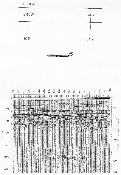
70 Range of applications of GPR contaminant plume mapping landfill investigations location of buried fuel tanks and oil drums detection of natural cavities and fissures void detection ice thickness mapping location of buried archaeological objects 70
71 Velocities of geological materials are very high corresponding wavelengths are in the range of decimeter. very good resolving of small structures Fig. 44: Wavelength of electro magnetic waves in dependence of signal frequency.7 71
72 Attenuation However, energy is lost due to attenuation which is dependent upon the electric ( ), magnetic ( ) and dielectric ( ) properties of the geological medium as well as the frequency of the radar signal. E0 =exp x Ex { [ = ]} 1/2 1/2 1 small values for air, ice, granite ideal conditions for GPR 72
73 Penetration Depth Penetration depth for georadar signal: [ m ] d [ m ]= 30 small penetration depths for rocks with low resistivities clay: 0.8 1m saturated sand 2m dry sand 5m 73
74 3.7.1 Models of data acquisition a) radar reflection profile: The transmitter and receiver antennae are kept at a small, fixed seperation. direct wave reflections Fig
75 Wave types Fig. 46 ³ 75
76 Radargram The observed signals can be summarized as radargram. Fig
77 Reflection 2 2 L/ 2 = x/ 2 h 2 L2 x 2 2 = h 4 4 L= x 4 h 2 Fig. 48 t= x 4 h v 77
78 Models of data acquisition b) wide angle reflection and refraction (WARR) sounding: The transmitter is kept at a fixed location and the receiver is towed away at increasing offsets. c) common depth point (CDP) method: Transmitter and receiver antennae are moved apart about a fixed central point. b and c are designed to show how the radar velocities change with depth. 78
79 Fig. 49: (A) WARR sounding and (B) CMP sounding with (C) a time distance moveout, and (D) the corresponding T² X² graph.¹ 79
80 Ground Penetrating Radar (GPR) Resolving power 4 vertical resolving: horizontal resolving: where v = f Example: z 4 f =100 MHz, v=0.1 m/ns =3 m The structures in the radargram local small anomalies: buried tanks, pipes hyperbola horizontal reflections: groundwater horizonts 80
81 Fig. 50: Origin of a radargram.7 81
82 Fig. 51: Schematic graph of the origin of diffraction. Tx: transmitter antenna, Rx: receiver antenna, R: reflection of groundwater table, D: diffraction.7 82

.")
83 3.7.2 Case Studies Fig. 52: Measurements with Ground Penetrating Radar. Left: 120 MHz antenna system (bistatic). Right: 500 MHz antenna system (monostatic).7 83


84 Case Studies Fig. 53: Example of a radargram: The reflector at 12 ns is caused by a sand/clay boundary. Fig. 54: Areal view of a radar mapping. The figure shows the 84 outlines of an antique water pipe.7
85 Fig. 55
86 Fig. 56
87 References 1) Reynolds, J. M.: An Introduction to Applied and Environmental Geophysics, Wiley, ) Kearey, P., Brooks, M.: An Introduction to Geophysical Exploration, Blackwell, ) Dietrich, P.: Introduction to Applied Geophysics, Script, Sept ) Vogelsang, D.: Environmental Geophysics, A Practical Guide, Springer Verlag, ) Tezkan, B.: A review of environmental applications of quasi stationary electromagnetic techniques, Surveys in Geophysics, 1999, 20,
88 References 6) Wilsom, J.: Field Geophysics, Wiley,1989 7) Kirsch, R.: Umweltgeophysik in der Praxis: Untersuchung von Altablagerungen und kontaminierten Standorten, Script 88
Electromagnetic Induction
 Electromagnetic Induction Recap the motivation for using geophysics We have problems to solve Slide 1 Finding resources Hydrocarbons Minerals Ground Water Geothermal Energy SEG Distinguished Lecture slide
Old & New? INTRODUCTION. The Best Proximal Geophysical Detector Ever!
 Measuring Soil Conductivity with Geonics Limited Electromagnetic Geophysical Instrumentation INTRODUCTION This presentation will briefly discuss the principles of operation and the practical applications
Geology 228/378 Environmental Geophysics Lecture 10. Electromagnetic Methods (EM) I And frequency EM (FEM)
 I And frequency EM (FEM)") Geology 228/378 Environmental Geophysics Lecture 10 Electromagnetic Methods (EM) I And frequency EM (FEM) Lecture Outline Introduction Principles Systems and Methods Case Histories Introduction Many EM
Geology 228/378 Environmental Geophysics Lecture 10 Electromagnetic Methods (EM) I And frequency EM (FEM) Lecture Outline Introduction Principles Systems and Methods Case Histories Introduction Many EM
7. Consider the following common offset gather collected with GPR.
 Questions: GPR 1. Which of the following statements is incorrect when considering skin depth in GPR a. Skin depth is the distance at which the signal amplitude has decreased by a factor of 1/e b. Skin
Here the goal is to find the location of the ore body, and then evaluate its size and depth.
 Geophysics 223 March 2009 D3 : Ground EM surveys over 2-D resistivity models D3.1 Tilt angle measurements In D2 we discussed approaches for mapping terrain conductivity. This is appropriate for many hydrogeology
HELICOPTER-BORNE GEOPHYSICAL SURVEY SYSTEMS
 HELICOPTER-BORNE GEOPHYSICAL SURVEY SYSTEMS APPLICATIONS: base & precious metals exploration diamondiferous kimberlite exploration geological mapping mapping of fault zones for engineering and mining applications
Radar Methods General Overview
 Environmental and Exploration Geophysics II Radar Methods General Overview tom.h.wilson tom.wilson@mail.wvu.edu Department of Geology and Geography West Virginia University Morgantown, WV Brown (2004)
Ground Penetrating Radar
 Ground Penetrating Radar Begin a new section: Electromagnetics First EM survey: GPR (Ground Penetrating Radar) Physical Property: Dielectric constant Electrical Permittivity EOSC 350 06 Slide Di-electric
SIMULATION OF GPR SCENARIOS USING FDTD
 SIMULATION OF GPR SCENARIOS USING FDTD 1 GAMIL ALSHARAHI, 2 ABDELLAH DRIOUACH, 3 AHMED FAIZE 1,2 Department of physic, Abdelmalek Essaâdi University, Faculty of sciences, Morocco 3 Department of physic,
Ground Penetrating Radar (day 1) EOSC Slide 1
 EOSC Slide 1") Ground Penetrating Radar (day 1) Slide 1 Introduction to GPR Today s Topics Setup: Motivational Problems Physical Properties - Dielectric Permittivity and Radiowaves - Microwave Example Basic Principles:
Ground Penetrating Radar (day 1) Slide 1 Introduction to GPR Today s Topics Setup: Motivational Problems Physical Properties - Dielectric Permittivity and Radiowaves - Microwave Example Basic Principles:
GPR SURVEY METHOD. Ground probing radar
 The ground penetrating radar (GPR - Ground Probing Radar) is a geophysical method used to investigate the near surface underground. Thanks to its high degree of resolution, the GPR is the most effective
Applied Geophysics Nov 2 and 4
 Applied Geophysics Nov 2 and 4 Effects of conductivity Surveying geometries Noise in GPR data Summary notes with essential equations Some Case histories EOSC 350 06 Slide 1 GPR Ground Penetrating Radar
Report. Mearns Consulting LLC. Former Gas Station 237 E. Las Tunas Drive San Gabriel, California Project # E
 Mearns Consulting LLC Report Former Gas Station 237 E. Las Tunas Drive San Gabriel, California Project #1705261E Charles Carter California Professional Geophysicist 20434 Corisco Street Chatsworth, CA
ωκε ωκε 5.11 Ground Penetrating Radar (GPR)
") 5. Ground Penetrating Radar (GPR) The plane wave solutions we have studied so far have been valid for frequencies and conductivities such that the conduction currents dominate the displacement currents
5. Ground Penetrating Radar (GPR) The plane wave solutions we have studied so far have been valid for frequencies and conductivities such that the conduction currents dominate the displacement currents
Geophysical Survey Rock Hill Bleachery TBA Site Rock Hill, South Carolina EP-W EPA, START 3, Region 4 TABLE OF CONTENTS Section Page Signature
 Geophysical Survey Rock Hill Bleachery TBA Site Rock Hill, South Carolina EP-W-05-054 EPA, START 3, Region 4 Prepared for: Tetra Tech EM, Inc. October 12, 2012 Geophysical Survey Rock Hill Bleachery TBA
Sferic signals for lightning sourced electromagnetic surveys
 Sferic signals for lightning sourced electromagnetic surveys Lachlan Hennessy* RMIT University hennessylachlan@gmail.com James Macnae RMIT University *presenting author SUMMARY Lightning strikes generate
GPR Part II: Effects of conductivity. Surveying geometries. Noise in GPR data. Summary notes with essential equations. Some Case histories
 GPR Part II: Effects of conductivity Surveying geometries Noise in GPR data Summary notes with essential equations Some Case histories EOSC 350 06 Slide 1 GPR Ground Penetrating Radar R = ε ε 2 2 + ε ε
The use of high frequency transducers, MHz, allowing the resolution to target a few cm thick in the first half meter suspect.
 METHODOLOGY GPR (GROUND PROBING RADAR). In recent years the methodology GPR (Ground Probing Radar) has been applied with increasing success under the NDT thanks to the high speed and resolving power. As
Technical Note TN-30 WHY DOESN'T GEONICS LIMITED BUILD A MULTI-FREQUENCY EM31 OR EM38? J.D. McNeill
 Tel: (905) 670-9580 Fax: (905) 670-9204 GEONICS LIMITED E-mail:geonics@geonics.com 1745 Meyerside Dr. Unit 8 Mississauaga, Ontario Canada L5T 1C6 URL:http://www.geonics.com Technical Note TN-30 WHY DOESN'T
Results of GPR survey of AGH University of Science and Technology test site (Cracow neighborhood).
.") Results of GPR survey of AGH University of Science and Technology test site (Cracow neighborhood). October 02, 2017 Two GPR sets were used for the survey. First GPR set: low-frequency GPR Loza-N [1]. Technical
Results of GPR survey of AGH University of Science and Technology test site (Cracow neighborhood). October 02, 2017 Two GPR sets were used for the survey. First GPR set: low-frequency GPR Loza-N [1]. Technical
Presented by: Mike Catalano GEONICS LIMITED
 What s In The Ground: A Non-Invasive Soil Mapping Tool! Presented by: Mike Catalano GEONICS LIMITED INTRODUCTION Measuring Soil Conductivity with Geonics Limited Electromagnetic Geophysical Instrumentation
Geology 228 Applied Geophysics Lecture 10. Electromagnetic Methods (EM) (Reynolds, Ch. 10, 11)
 (Reynolds, Ch. 10, 11)") Geology 228 Applied Geophysics Lecture 10 Electromagnetic Methods (EM) (Reynolds, Ch. 10, 11) Lecture Outline Introduction Principles Systems and Methods (FDEM & TDEM) Case Histories APPLICATIONS 1. Mineral
Geology 228 Applied Geophysics Lecture 10 Electromagnetic Methods (EM) (Reynolds, Ch. 10, 11) Lecture Outline Introduction Principles Systems and Methods (FDEM & TDEM) Case Histories APPLICATIONS 1. Mineral
A COMPARISON OF ELECTRODE ARRAYS IN IP SURVEYING
 A COMPARISON OF ELECTRODE ARRAYS IN IP SURVEYING John S. Sumner Professor of Geophysics Laboratory of Geophysics and College of Mines University of Arizona Tucson, Arizona This paper is to be presented
ARCHAEOLOGICAL GEOPHYSICS: SENSOR SELECTION AND SITE SUITABILITY
 ARCHAEOLOGICAL GEOPHYSICS: SENSOR SELECTION AND SITE SUITABILITY A SPARC Webinar presented on October 17, 2014 Eileen G. Ernenwein, PhD ETSU: http://faculty.etsu.edu/ernenwei/ CAST: http://goo.gl/wyzlp
# DEFINITIONS TERMS. 2) Electrical energy that has escaped into free space. Electromagnetic wave
 Electrical energy that has escaped into free space. Electromagnetic wave") CHAPTER 14 ELECTROMAGNETIC WAVE PROPAGATION # DEFINITIONS TERMS 1) Propagation of electromagnetic waves often called radio-frequency (RF) propagation or simply radio propagation. Free-space 2) Electrical
CHAPTER 14 ELECTROMAGNETIC WAVE PROPAGATION # DEFINITIONS TERMS 1) Propagation of electromagnetic waves often called radio-frequency (RF) propagation or simply radio propagation. Free-space 2) Electrical
(i) Determine the admittance parameters of the network of Fig 1 (f) and draw its - equivalent circuit.
 Determine the admittance parameters of the network of Fig 1 (f) and draw its - equivalent circuit.") I.E.S-(Conv.)-1995 ELECTRONICS AND TELECOMMUNICATION ENGINEERING PAPER - I Some useful data: Electron charge: 1.6 10 19 Coulomb Free space permeability: 4 10 7 H/m Free space permittivity: 8.85 pf/m Velocity
I.E.S-(Conv.)-1995 ELECTRONICS AND TELECOMMUNICATION ENGINEERING PAPER - I Some useful data: Electron charge: 1.6 10 19 Coulomb Free space permeability: 4 10 7 H/m Free space permittivity: 8.85 pf/m Velocity
Groundwave Propagation, Part One
 Groundwave Propagation, Part One 1 Planar Earth groundwave 2 Planar Earth groundwave example 3 Planar Earth elevated antenna effects Levis, Johnson, Teixeira (ESL/OSU) Radiowave Propagation August 17,
Radio Propagation Fundamentals
 Radio Propagation Fundamentals Concept of Electromagnetic Wave Propagation Mechanisms Modes of Propagation Propagation Models Path Profiles Link Budget Fading Channels Electromagnetic (EM) Waves EM Wave
Stratagem EH4 Geometrics, Inc.
 Stratagem EH4 Geometrics, Inc. Stratagem EH4 Hybrid-Source Magnetotellurics Frequency range of 10 Hz to 90k Hz Approx. depth of investigation from 5m to 1km Portable with rapid setup and teardown Full
European Scientific Journal February 2014 /SPECIAL/ edition vol.3 ISSN: (Print) e - ISSN
 e - ISSN") HIGH PRECISION CALCULATION OF MOVE OUT CORRECTION IN GPR MEASUREMENTS Janis Karuss, M.Sc. University of Latvia, Latvia Abstract Ground penetrating radar (GPR) is a non-invasive geophysical method that
HIGH PRECISION CALCULATION OF MOVE OUT CORRECTION IN GPR MEASUREMENTS Janis Karuss, M.Sc. University of Latvia, Latvia Abstract Ground penetrating radar (GPR) is a non-invasive geophysical method that
GPR MEASUREMENTS OF WATER LEVEL IN SILTY SOILS. Sandeep Pyakurel
 GPR MEASUREMENTS OF WATER LEVEL IN SILTY SOILS Sandeep Pyakurel Problem report submitted to the College of Engineering and Mineral Resources at West Virginia University in partial fulfillment of the requirements
GPR Data Acquisition and Interpretation
 1 GPR Data Acquisition and Interpretation Mezgeen Rasol PhD Candidate Geophysics and Seismic Engineering Polytechnic University of Catalonia mezgeen.rasol@upc.edu BIG-SKY-EARTH Cost Action TD143 Workshop
Chapter 15: Radio-Wave Propagation
 Chapter 15: Radio-Wave Propagation MULTIPLE CHOICE 1. Radio waves were first predicted mathematically by: a. Armstrong c. Maxwell b. Hertz d. Marconi 2. Radio waves were first demonstrated experimentally
Increasing the Probability of Detection and Evaluation of Buried Metallic Objects by Data Fusion GPR- Low Frequency Electromagnetic Sensor Array
 4th European-American Workshop on Reliability of NDE - Poster 4 Increasing the Probability of Detection and Evaluation of Buried Metallic Objects by Data Fusion GPR- Low Frequency Electromagnetic Sensor
GCM mapping Vildbjerg - HydroGeophysics Group - Aarhus University
 GCM mapping Vildbjerg - HydroGeophysics Group - Aarhus University GCM mapping Vildbjerg Report number 06-06-2017, June 2017 Indholdsfortegnelse 1. Project information... 2 2. DUALEM-421s... 3 2.1 Setup
Dragging Exploration into the Quantum Age: using Atomic Dielectric Resonance technology to classify sites in the North Atlantic Craton
 Dragging Exploration into the Quantum Age: using Atomic Dielectric Resonance technology to classify sites in the North Atlantic Craton Gordon D.C. Stove CEO & Co-founder Agenda What is Atomic Dielectric
Characterizing Subsurface Structures using Very Low Frequency Electromagnetic Radiation - a Modeling Approach
 Characterizing Subsurface Structures using Very Low Frequency Electromagnetic Radiation - a Modeling Approach ERNST D. SCHMITTER University of Applied Sciences Department of Engineering and Computer Sciences
Pitfalls in GPR Data Interpretation: Differentiating Stratigraphy and Buried Objects from Periodic Antenna and Target Effects
 GEOPHYSICAL RESEARCH LETTERS, VOL. 27, NO. 20, PAGES 3393-3396, OCTOBER 15, 2000 Pitfalls in GPR Data Interpretation: Differentiating Stratigraphy and Buried Objects from Periodic Antenna and Target Effects
Ionospheric Absorption
 Ionospheric Absorption Prepared by Forrest Foust Stanford University, Stanford, CA IHY Workshop on Advancing VLF through the Global AWESOME Network VLF Injection Into the Magnetosphere Earth-based VLF
GROUND PENETRATING RADAR (GPR)
") Introduction GROUND PENETRATING RADAR (GPR) (After Basson 2000) GPR is an electromagnetic (EM) geophysical method for high-resolution detection, imaging and mapping of subsurface soils and rock conditions.
Introduction GROUND PENETRATING RADAR (GPR) (After Basson 2000) GPR is an electromagnetic (EM) geophysical method for high-resolution detection, imaging and mapping of subsurface soils and rock conditions.
DISTORTION OF VLF RADIO WAVE FIELD VERTICAL METAL POLES.
 Title DISTORTION OF VLF RADIO WAVE FIELD VERTICAL METAL POLES Author(s) KIKUCHI, Takashi; ARAKI, Tohru Citation Contributions of the Geophysical In (1972), 12: 1-5 Issue Date 1972-12 URL http://hdl.handle.net/2433/178624
RESISTIVITY METHODS MT
 Presented at Short Course V on Exploration for Geothermal Resources, organized by UNU-GTP, GDC and KenGen, at Lake Bogoria and Lake Naivasha, Kenya, Oct. 29 Nov. 19, 2010. GEOTHERMAL TRAINING PROGRAMME
h max 20 TX Ionosphere d 1649 km Radio and Optical Wave Propagation Prof. L. Luini, July 1 st, 2016 SURNAME AND NAME ID NUMBER SIGNATURE
 Radio and Optical Wave Propagation Prof. L. Luini, July st, 06 3 4 do not write above SURNAME AND NAME ID NUMBER SIGNATURE Exercise Making reference to the figure below, the transmitter TX, working at
The application of GPR for the modeling of ERT data and the evaluation of resolution for different electrode configurations
 BACHELOR THESIS The application of GPR for the modeling of ERT data and the evaluation of resolution for different TU Wien Department of Geodesy and Geoinformation Research Group Geophysics Performed by
Waveguides. Metal Waveguides. Dielectric Waveguides
 Waveguides Waveguides, like transmission lines, are structures used to guide electromagnetic waves from point to point. However, the fundamental characteristics of waveguide and transmission line waves
Microwave and optical systems Introduction p. 1 Characteristics of waves p. 1 The electromagnetic spectrum p. 3 History and uses of microwaves and
 Microwave and optical systems Introduction p. 1 Characteristics of waves p. 1 The electromagnetic spectrum p. 3 History and uses of microwaves and optics p. 4 Communication systems p. 6 Radar systems p.
Ground Penetrating Radar (GPR) By Dr. Eng. Zubair Ahmed
 By Dr. Eng. Zubair Ahmed") Ground Penetrating Radar (GPR) By Dr. Eng. Zubair Ahmed Acknowledgement Golder Associates, Whitby, Ontario Stantec Consulting, Kitchener, Ontario Infrasense Inc. USA Geophysical Survey Systems Inc. (GSSI),
Ground Penetrating Radar (GPR) By Dr. Eng. Zubair Ahmed Acknowledgement Golder Associates, Whitby, Ontario Stantec Consulting, Kitchener, Ontario Infrasense Inc. USA Geophysical Survey Systems Inc. (GSSI),
OBJECTIVES: PROPAGATION INTRO RADIO WAVES POLARIZATION LINE OF SIGHT, GROUND WAVE, SKY WAVE IONOSPHERE REGIONS PROPAGATION, HOPS, SKIPS ZONES THE
 WAVE PROPAGATION OBJECTIVES: PROPAGATION INTRO RADIO WAVES POLARIZATION LINE OF SIGHT, GROUND WAVE, SKY WAVE IONOSPHERE REGIONS PROPAGATION, HOPS, SKIPS ZONES THE IONOSPHERIC LAYERS ABSORPTION AND FADING
Chapter 21. Alternating Current Circuits and Electromagnetic Waves
 Chapter 21 Alternating Current Circuits and Electromagnetic Waves AC Circuit An AC circuit consists of a combination of circuit elements and an AC generator or source The output of an AC generator is sinusoidal
Technical Note TN-31 APPLICATION OF DIPOLE-DIPOLE ELECTROMAGNETIC SYSTEMS FOR GEOLOGICAL DEPTH SOUNDING. Introduction
 Technical Note TN-31 APPLICATION OF DIPOLE-DIPOLE ELECTROMAGNETIC SYSTEMS FOR GEOLOGICAL DEPTH SOUNDING Introduction In Geonics Limited Technical Note TN-30 Why Doesn t Geonics Limited Build a Multi- Frequency
Propagation of EM Waves in material media
 Propagation of EM Waves in material media S.M.Lea 017 1 Wave propagation As usual, we start with Maxwell s euations with no free charges: =0 =0 = = + If we now assume that each field has the plane wave
GROUND PENETRATING RADAR (GEORADAR) INSPECTION
 INSPECTION") - CIVIL ENGENEERING - GEOLOGY AND ENVIRONMENT - GROUND PENETRATING RADAR - LOSSES DETECTING RADAR SYSTEM - ARCHEOLOGY & CULTURAL HERITAGE - CARGO INSPECTION - LOSS CONTROL - CHEMICAL ANALYSIS - INDUSTRIAL
- CIVIL ENGENEERING - GEOLOGY AND ENVIRONMENT - GROUND PENETRATING RADAR - LOSSES DETECTING RADAR SYSTEM - ARCHEOLOGY & CULTURAL HERITAGE - CARGO INSPECTION - LOSS CONTROL - CHEMICAL ANALYSIS - INDUSTRIAL
Propagation curves and conditions of validity (homogeneous paths)
") Rec. ITU-R P.368-7 1 RECOMMENDATION ITU-R P.368-7 * GROUND-WAVE PROPAGATION CURVES FOR FREQUENCIES BETWEEN 10 khz AND 30 MHz (1951-1959-1963-1970-1974-1978-1982-1986-1990-1992) Rec. 368-7 The ITU Radiocommunication
Rec. ITU-R P.368-7 1 RECOMMENDATION ITU-R P.368-7 * GROUND-WAVE PROPAGATION CURVES FOR FREQUENCIES BETWEEN 10 khz AND 30 MHz (1951-1959-1963-1970-1974-1978-1982-1986-1990-1992) Rec. 368-7 The ITU Radiocommunication
An acousto-electromagnetic sensor for locating land mines
 An acousto-electromagnetic sensor for locating land mines Waymond R. Scott, Jr. a, Chistoph Schroeder a and James S. Martin b a School of Electrical and Computer Engineering b School of Mechanical Engineering
(A) 2f (B) 2 f (C) f ( D) 2 (E) 2
 2f (B) 2 f (C) f ( D) 2 (E) 2") 1. A small vibrating object S moves across the surface of a ripple tank producing the wave fronts shown above. The wave fronts move with speed v. The object is traveling in what direction and with what
1. A small vibrating object S moves across the surface of a ripple tank producing the wave fronts shown above. The wave fronts move with speed v. The object is traveling in what direction and with what
SHIELDING EFFECTIVENESS
 SHIELDING Electronic devices are commonly packaged in a conducting enclosure (shield) in order to (1) prevent the electronic devices inside the shield from radiating emissions efficiently and/or (2) prevent
Investigating multi-polarization GPR wave transmission through thin layers: Implications for vertical fracture characterization
 GEOPHYSICAL RESEARCH LETTERS, VOL. 33, L20401, doi:10.1029/2006gl027788, 2006 Investigating multi-polarization GPR wave transmission through thin layers: Implications for vertical fracture characterization
Experiment on Artificial Frozen Soil Boundary GPR Detection During Cross-passage Construction in Tunnels
 354 Progress In Electromagnetics Research Symposium 2005, Hangzhou, China, August 22-26 Experiment on Artificial Frozen Soil Boundary GPR Detection During Cross-passage Construction in Tunnels Yong-Hui
P Forsmark site investigation. RAMAC and BIPS logging in borehole HFM11 and HFM12
 P-04-39 Forsmark site investigation RAMAC and BIPS logging in borehole HFM11 and HFM12 Jaana Gustafsson, Christer Gustafsson Malå Geoscience AB/RAYCON March 2004 Svensk Kärnbränslehantering AB Swedish
Session2 Antennas and Propagation
 Wireless Communication Presented by Dr. Mahmoud Daneshvar Session2 Antennas and Propagation 1. Introduction Types of Anttenas Free space Propagation 2. Propagation modes 3. Transmission Problems 4. Fading
Detection of Pipelines using Sub-Audio Magnetics (SAM)
") Gap Geophysics Australia Pty Ltd. Detection of Pipelines using Sub-Audio Magnetics is a patented technique developed by Gap Geophysics. The technique uses a fast sampling magnetometer to monitor magnetic
Gap Geophysics Australia Pty Ltd. Detection of Pipelines using Sub-Audio Magnetics is a patented technique developed by Gap Geophysics. The technique uses a fast sampling magnetometer to monitor magnetic
Archaeo-Geophysical Associates, LLC
 Geophysical Survey at the Parker Cemetery Rockwall, Texas. AGA Report 2010-6 Report Submitted To: Texas Cemetery Restoration 10122 Cherry Tree Dr. Dallas, Texas 75243 May 14, 2010 Chester P. Walker, Ph.D.
Telecommunication Systems February 14 th, 2019
 Telecommunication Systems February 14 th, 019 1 3 4 5 do not write above SURNAME AND NAME ID NUMBER SIGNATURE Problem 1 A radar with zenithal pointing, working at f = 5 GHz, illuminates an aircraft with
WHAT ARE WE MEASURING?
 WHAT ARE WE MEASURING? ASEG Workshop on Airborne Electromagnetics P th Perth November 7th 2012 P. Mutton, Consulting Geophysicist Southern Geoscience Consultants www.sgc.com.au WHAT ARE WE MEASURING? OUTLINE
SCATTERING POLARIMETRY PART 1. Dr. A. Bhattacharya (Slide courtesy Prof. E. Pottier and Prof. L. Ferro-Famil)
") SCATTERING POLARIMETRY PART 1 Dr. A. Bhattacharya (Slide courtesy Prof. E. Pottier and Prof. L. Ferro-Famil) 2 That s how it looks! Wave Polarisation An electromagnetic (EM) plane wave has time-varying
SCATTERING POLARIMETRY PART 1 Dr. A. Bhattacharya (Slide courtesy Prof. E. Pottier and Prof. L. Ferro-Famil) 2 That s how it looks! Wave Polarisation An electromagnetic (EM) plane wave has time-varying
Statement of Qualifications
 Revised January 29, 2011 ClearView Geophysics Inc. 12 Twisted Oak Street Brampton, ON L6R 1T1 Canada Phone: (905) 458-1883 Fax: (905) 792-1884 general@geophysics.ca www.geophysics.ca 1 1. Introduction
Using ground penetrating radar to quantify changes in the fracture pattern associated with a simulated rockburst experiment
 Using ground penetrating radar to quantify changes in the fracture pattern associated with a simulated rockburst experiment by M. Grodner* Synopsis Ground Penetrating Radar (GPR) is an electromagnetic
Final Examination. 22 April 2013, 9:30 12:00. Examiner: Prof. Sean V. Hum. All non-programmable electronic calculators are allowed.
 UNIVERSITY OF TORONTO FACULTY OF APPLIED SCIENCE AND ENGINEERING The Edward S. Rogers Sr. Department of Electrical and Computer Engineering ECE 422H1S RADIO AND MICROWAVE WIRELESS SYSTEMS Final Examination
Photograph of the rectangular waveguide components
 Waveguides Photograph of the rectangular waveguide components BACKGROUND A transmission line can be used to guide EM energy from one point (generator) to another (load). A transmission line can support
Polarization orientation of the electric field vector with respect to the earth s surface (ground).
.") Free space propagation of electromagnetic waves is often called radio-frequency (rf) propagation or simply radio propagation. The earth s atmosphere, as medium introduces losses and impairments to the
Free space propagation of electromagnetic waves is often called radio-frequency (rf) propagation or simply radio propagation. The earth s atmosphere, as medium introduces losses and impairments to the
UNIT Derive the fundamental equation for free space propagation?
 UNIT 8 1. Derive the fundamental equation for free space propagation? Fundamental Equation for Free Space Propagation Consider the transmitter power (P t ) radiated uniformly in all the directions (isotropic),
I p = V s = N s I s V p N p
 UNIT G485 Module 1 5.1.3 Electromagnetism 11 For an IDEAL transformer : electrical power input = electrical power output to the primary coil from the secondary coil Primary current x primary voltage =
Downloaded from library.seg.org by on 10/26/14. For personal use only. SEG Technical Program Expanded Abstracts 2014
 Ground penetrating abilities of broadband pulsed radar in the 1 70MHz range K. van den Doel, Univ. of British Columbia, J. Jansen, Teck Resources Limited, M. Robinson, G. C, Stove, G. D. C. Stove, Adrok
Electrical Resistivity Imaging
 Approved for Public Release; Distribution Unlimited Electrical Resistivity Imaging David Hull US Army Research Lab hull@arl.army.mil 17 Jun 2009 ARL Workshop on Personnel, Vehicle, and Tunnel Detection
Tri-band ground penetrating radar for subsurface structural condition assessments and utility mapping
 Tri-band ground penetrating radar for subsurface structural condition assessments and utility mapping D. Huston *1, T. Xia 1, Y. Zhang 1, T. Fan 1, J. Razinger 1, D. Burns 1 1 University of Vermont, Burlington,
On measuring electromagnetic surface impedance - Discussions with Professor James R. Wait
 On measuring electromagnetic surface impedance - Discussions with Professor James R. Wait Author Thiel, David Published 2000 Journal Title IEEE Transactions on Antennas and Propagation DOI https://doi.org/10.1109/8.899667
VALIDATION OF GROUND PENETRATING RADAR DATA INTERPRETATION USING AN ELECTROMAGNETIC WAVE PROPAGATION SIMULATOR
 Romanian Reports in Physics, Vol. 68, No. 4, P. 1584 1588, 2016 VALIDATION OF GROUND PENETRATING RADAR DATA INTERPRETATION USING AN ELECTROMAGNETIC WAVE PROPAGATION SIMULATOR A. CHELMUS National Institute
Application of Ground Penetrating Radar for River Ice Surveys
 CGU HS Committee on River Ice Processes and the Environment 14th Workshop on the Hydraulics of Ice Covered Rivers Quebec City, June 19-22, 2007 Application of Ground Penetrating Radar for River Ice Surveys
A NOVEL ANALYSIS OF ULTRA-WIDEBAND PLANAR DIPOLE ARRAY ANTENNA
 Volume 120 No. 6 2018, 9783-9793 ISSN: 1314-3395 (on-line version) url: http://www.acadpubl.eu/hub/ http://www.acadpubl.eu/hub/ A NOVEL ANALYSIS OF ULTRA-WIDEBAND PLANAR DIPOLE ARRAY ANTENNA SVSPrasad
RADIOWAVE PROPAGATION
 RADIOWAVE PROPAGATION Physics and Applications CURT A. LEVIS JOEL T. JOHNSON FERNANDO L. TEIXEIRA The cover illustration is part of a figure from R.C. Kirby, "Introduction," Lecture 1 in NBS Course in
Physics B Waves and Sound Name: AP Review. Show your work:
 Physics B Waves and Sound Name: AP Review Mechanical Wave A disturbance that propagates through a medium with little or no net displacement of the particles of the medium. Parts of a Wave Crest: high point
Application and signal transmission of the VLF electromagnetic wave in mine rock
 Application and signal transmission of the VLF electromagnetic wave in mine rock Zheng Zhang School of Civil and Environment Engineering, University of Science and Technology Beijing, 100083, China Abstract
Advanced Ground Investigation Techniques to Help Limit Risk or Examine Failure. Advanced Subsurface Investigations
 Advanced Ground Investigation Techniques to Help Limit Risk or Examine Failure Overview Introduction What is geophysics? Why use it? Common Methods Seismic Ground Radar Electrical Case Studies Conclusion
Analysis of Crack Detection in Metallic and Non-metallic Surfaces Using FDTD Method
 ECNDT 26 - We.4.3.2 Analysis of Crack Detection in Metallic and Non-metallic Surfaces Using FDTD Method Faezeh Sh.A.GHASEMI 1,2, M. S. ABRISHAMIAN 1, A. MOVAFEGHI 2 1 K. N. Toosi University of Technology,
Simulation of the Near-field of a Ferrite Antenna
 Simulation of the Near-field of a Ferrite Antenna Alexey A. Kalmykov, Kirill D. Shaidurov, and Stanislav O. Polyakov Ural Federal University named after the first President of Russia B.N.Yeltsin Ekaterinburg,
Advanced Utility Locating Technologies (R01B)
") Advanced Utility Locating Technologies (R01B) Jacob Sheehan Senior Geophysicist Olson Engineering Phil Sirles Principal Geophysicist Olson Engineering Introduction: Utility Bundle Overview SHRP2 Strategic
Advanced Utility Locating Technologies (R01B) Jacob Sheehan Senior Geophysicist Olson Engineering Phil Sirles Principal Geophysicist Olson Engineering Introduction: Utility Bundle Overview SHRP2 Strategic
DETECTION OF CORROSION IN BOTTOM PLATES OF GAS AND OIL TANKS USING GUIDED ULTRASONIC WAVES AND ELECTROMAGNETIC ULTRASONIC (EMAT) TRANSDUCERS
 TRANSDUCERS") DETECTION OF CORROSION IN BOTTOM PLATES OF GAS AND OIL TANKS USING GUIDED ULTRASONIC WAVES AND ELECTROMAGNETIC ULTRASONIC (EMAT) TRANSDUCERS A Presentation prepared for the Jahrestagung der Deutsche Gesellschaft
DETECTION OF CORROSION IN BOTTOM PLATES OF GAS AND OIL TANKS USING GUIDED ULTRASONIC WAVES AND ELECTROMAGNETIC ULTRASONIC (EMAT) TRANSDUCERS A Presentation prepared for the Jahrestagung der Deutsche Gesellschaft
L O C A T O R G P R. Introducing the. Radarteam. Ground Probing Radar/Antenna system with Rugged PC and Cart ü
 Introducing the L O C A T O R G P R Ground Probing Radar/Antenna system with Rugged PC and Cart ü Fully integrated system. Multi Frequency operation: 100-900 MHz ü Air/Ground Coupled operation. Multiple
DEVELOPMENT OF VERY LOW FREQUENCY SELF-NULLING PROBE FOR INSPECTION OF THICK LAYERED ALUMINUM STRUCTURES
 DEVELOPMENT OF VERY LOW FREQUENCY SELF-NULLING PROBE FOR INSPECTION OF THICK LAYERED ALUMINUM STRUCTURES Buzz Wincheski and Min Namkung NASA Langley Research Center Hampton, VA 23681 INTRODUCTION Nondestructive
Identification of Pipelines from the Secondary Reflect Wave Travel Time of Ground-Penetrating Radar Waves
 Journal of Emerging Trends in Engineering and Applied Sciences (JETEAS) 2 (5): 770-774 Scholarlink Research Institute Journals, 2011 (ISSN: 2141-7016) jeteas.scholarlinkresearch.org Journal of Emerging
Contents. Contents. Contents. Lecture Note on Wireless Communication Engineering I. Wireless Communication Engineering 1
 Lecture Note on Wireless Communication Engineering I Prof. Kiyomichi Araki Department of Electrical & Electronics Tokyo Institute of Technology South III Bld. Room No. 91 TEL/FAX: +81-3-5734-3495 E-mail:
GPR Investigation: Post Tension Cable Mapping
 CMD Civil Pty Ltd PO Box 1119 Huntingdale VIC 3166 +61 3 9544 8833 info@cmdcivil.com www.cmdcivil.com Case Study: GPR Investigation: Post Tension Cable Mapping This application note demonstrates an example
Using GPR Technique Assessment for Study the Sub-Grade of Asphalt and Concrete Conditions
 Using GPR Technique Assessment for Study the Sub-Grade of Asphalt and Concrete Conditions Alaa S. Mahdi Remote Sensing Unit, College of Science, University of Baghdad, Baghdad, Iraq Abstract The Ground
Rec. ITU-R P RECOMMENDATION ITU-R P *
 Rec. ITU-R P.682-1 1 RECOMMENDATION ITU-R P.682-1 * PROPAGATION DATA REQUIRED FOR THE DESIGN OF EARTH-SPACE AERONAUTICAL MOBILE TELECOMMUNICATION SYSTEMS (Question ITU-R 207/3) Rec. 682-1 (1990-1992) The
THE FEASIBILITY OF THE AIRBORNE FLUXGATE MAGNETOMETER AS AN EXPLORATION TOOL RESULTS FROM THREE DIMENSIONAL NUMERICAL MODELLING
 THE FEASIBILITY OF THE AIRBORNE FLUXGATE MAGNETOMETER AS AN EXPLORATION TOOL RESULTS FROM THREE DIMENSIONAL NUMERICAL MODELLING John Joseph CRC LEME, School of Earth and Environmental Sciences, University
We are IntechOpen, the world s leading publisher of Open Access books Built by scientists, for scientists. International authors and editors
 We are IntechOpen, the world s leading publisher of Open Access books Built by scientists, for scientists 3,500 108,000 1.7 M Open access books available International authors and editors Downloads Our
Chapter Ray and Wave Optics
 109 Chapter Ray and Wave Optics 1. An astronomical telescope has a large aperture to [2002] reduce spherical aberration have high resolution increase span of observation have low dispersion. 2. If two
Module 2 WAVE PROPAGATION (Lectures 7 to 9)
") Module 2 WAVE PROPAGATION (Lectures 7 to 9) Lecture 9 Topics 2.4 WAVES IN A LAYERED BODY 2.4.1 One-dimensional case: material boundary in an infinite rod 2.4.2 Three dimensional case: inclined waves 2.5
Module 2 WAVE PROPAGATION (Lectures 7 to 9) Lecture 9 Topics 2.4 WAVES IN A LAYERED BODY 2.4.1 One-dimensional case: material boundary in an infinite rod 2.4.2 Three dimensional case: inclined waves 2.5
TECHNICAL NOTE EXTREMELY LOW FREQUENCY (ELF) EM SYSTEM
 EM SYSTEM") TECHNICAL NOTE 2012-01 EXTREMELY LOW FREQUENCY (ELF) EM SYSTEM Dave Hildes, Ph.D, P. Geol Aurora Geoscicences Ltd. 34A Laberge Road, Whitehorse, YT, Y1A 5Y9 techniques such as MT / CSAMT / large-loop TEM.
TECHNICAL NOTE 2012-01 EXTREMELY LOW FREQUENCY (ELF) EM SYSTEM Dave Hildes, Ph.D, P. Geol Aurora Geoscicences Ltd. 34A Laberge Road, Whitehorse, YT, Y1A 5Y9 techniques such as MT / CSAMT / large-loop TEM.
TOPIC 2 WAVEGUIDE AND COMPONENTS
 TOPIC 2 WAVEGUIDE AND COMPONENTS COURSE LEARNING OUTCOME (CLO) CLO1 Explain clearly the generation of microwave, the effects of microwave radiation and the propagation of electromagnetic in a waveguide