TOPIC 2 WAVEGUIDE AND COMPONENTS
|
|
|
- Gervase Haynes
- 6 years ago
- Views:
Transcription
1 TOPIC 2 WAVEGUIDE AND COMPONENTS
2 COURSE LEARNING OUTCOME (CLO) CLO1 Explain clearly the generation of microwave, the effects of microwave radiation and the propagation of electromagnetic in a waveguide and its accessories CLO2 Apply given mathematical equations or Smith Chart to solve problem related to microwave propagation.
3 CLO3 Handle systematically the related microwave communication equipment in performing the assigned practical work.
4 Understand the characteristic of waveguide Upon completion of this topic, students should be able to: 1. Define a) Critical (cut-off) frequency b) Critical (cut-off) wavelength 2. Explain the following terminologies: Group velocity, Phase velocity, propagation wavelength, waveguide characteristic impedance 3. Calculate the item no.1 and no. 2 for rectangular and circular waveguide

5 Rectangular Waveguide With; a = broad dimension b = narrow dimension x = length waveguide Dimensions of the waveguide which determines the operating frequency range
6 Dimensions of the waveguide which determines the operating frequency range: 1. The size of the waveguide determines its operating frequency range. 2. The frequency of operation is determined by the dimension a. 3. This dimension is usually made equal to one half the wavelength at the lowest frequency of operation, this frequency is known as the waveguide cutoff frequency. 4. At the cutoff frequency and below, the waveguide will not transmit energy. At frequencies above the cutoff frequency, the waveguide will propagate energy.

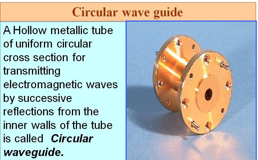
7 Circular waveguide r = radius x = length waveguide
8 Characteristic of waveguide Waveguides are basically a device ("a guide") for transporting electromagnetic energy from one region to another. They are capable of directing power precisely to where it is needed, can handle large amounts of power and function as a high-pass filter.
9 The waveguide acts as a high pass filter in that most of the energy above a certain frequency (the cutoff frequency) will pass through the waveguide, whereas most of the energy that is below the cutoff frequency will be attenuated by the waveguide.

10
11 Critical (cut-off) Frequency, Fc The cutoff frequency is the frequency at which all lower frequencies are attenuated by the waveguide, and above the cutoff frequency all higher frequencies propagate within the waveguide. The cutoff frequency defines the high-pass filter characteristic of the waveguide: above this frequency, the waveguide passes power, below this frequency the waveguide attenuates or blocks power.
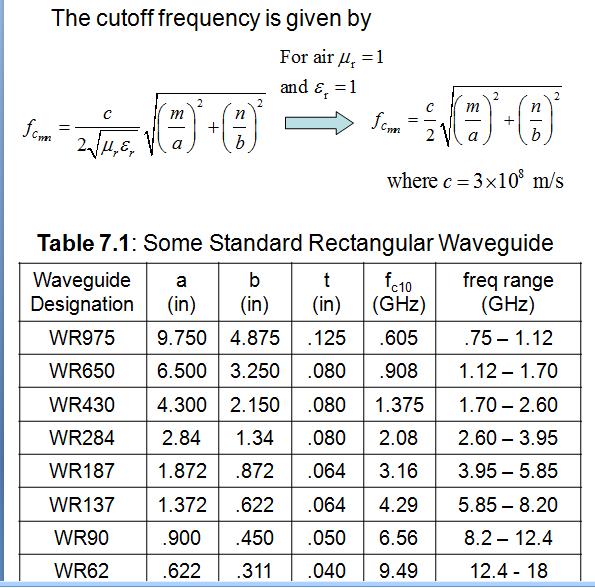
12 The cutoff frequency depends on the shape and size of the cross section of the waveguide. The larger the waveguide is, the lower the cutoff frequency for that waveguide is. The formula for the cutoff frequency of a rectangular cross sectioned waveguide is given by: - permeability - permittivity
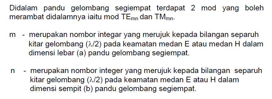
13 Rectangular Waveguide Let us consider a rectangular waveguide with interior dimensions are a x b, Waveguide can support TE and TM modes. In TE modes, the electric field is transverse to the direction of propagation. In TM modes, the magnetic field that is transverse and an electric field component is in the propagation direction. The order of the mode refers to the field configuration in the guide, and is given by m and n integer subscripts, TE mn and TM mn. The m subscript corresponds to the number of halfwave variations of the field in the x direction, and The n subscript is the number of half-wave variations in the y direction.
14 Location of Modes
15 Rectangular Waveguide A particular mode is only supported above its cutoff frequency. The cutoff frequency is given by f c mn m n c m n 2 a b 2 a b r r where c m/s
16 Rectangular Waveguide
17
18 Formula
19 Dominant Mode The dominant mode is the mode with lowest cutoff frequency. It s always TE 10 The order of the next modes change depending on the dimensions of the guide.
20 Group and Phase velocity How fast is the wave traveling? Velocity is a reference distance divided by a reference time. Group velocity is the velocity at which the energy of the wave propagates. This means that the wave moves at the speed of vg. Phase velocity is the speed of movement of a point of constant phase in a continous wave. Group and phase velocities have the same value in free space and in parallel wire transmission lines.
21

22 Group and Phase velocity
23 The Phase velocity This is the velocity at which the overall shape of the wave s amplitudes, or the wave envelope, propagates. (= signal velocity) Here, phase velocity = group velocity (the medium is nondispersive)
24 Group velocity

25 Dispersion: phase/group velocity depends on frequency Black dot moves at phase velocity. Red dot moves at group velocity. This is normal dispersion (refractive index decreases with increasing λ)

26 Rectangular Waveguide Need to find the fields components of the em wave inside the waveguide E z H z E x H x E y H y We ll find that waveguides don t support TEM waves
27
28 The m and n represent the mode of propagation and indicates the number of variations of the field in the x and y directions Note that for the TM mode, if n or m is zero, all fields are zero.
29 Variation of wave impedance Wave impedance varies with frequency and mode
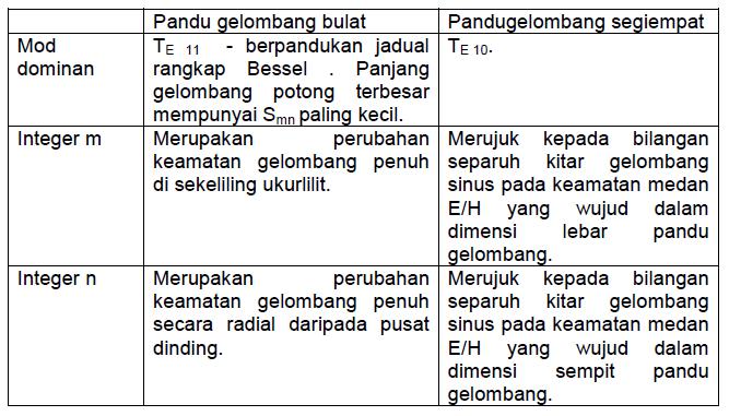
30 Rectangular Waveguide - Wave Propagation
31 Wave Guide Impedance Wave feature impedance for TE mode is ZTE = with; ZTE = characteristic impedance for TE mode 377 = free space feature impedance = free space wavelength 0 = wavelength cut. 2
32 Wave Guide Impedance Wave feature impedance for TM mode is ZTM = ( 0 ) 2 where; ZTM = characteristic impedance for TM mode 377 = free space feature impedance = free space wavelength 0 = wavelength cut.
33 Question Waveguide
34
35
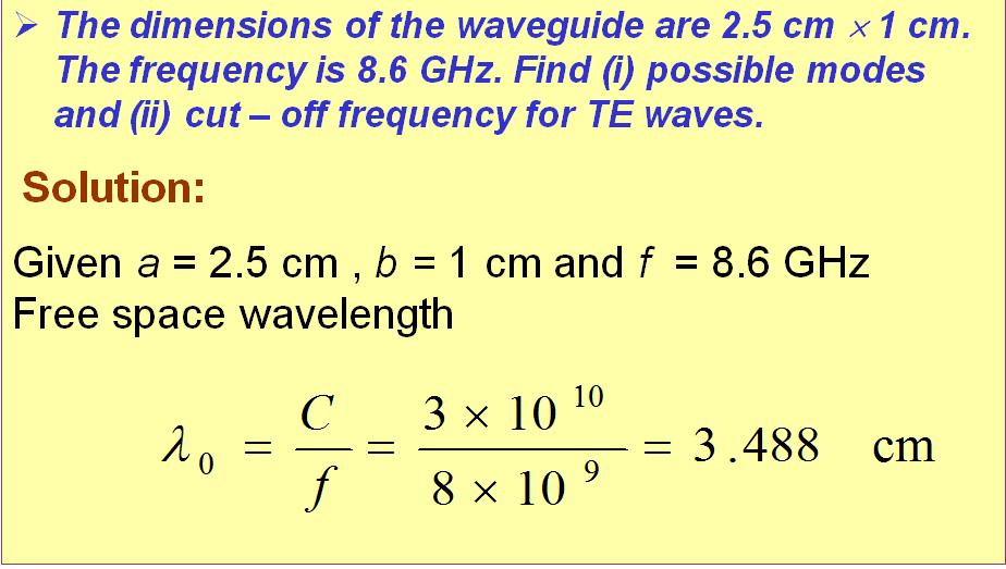
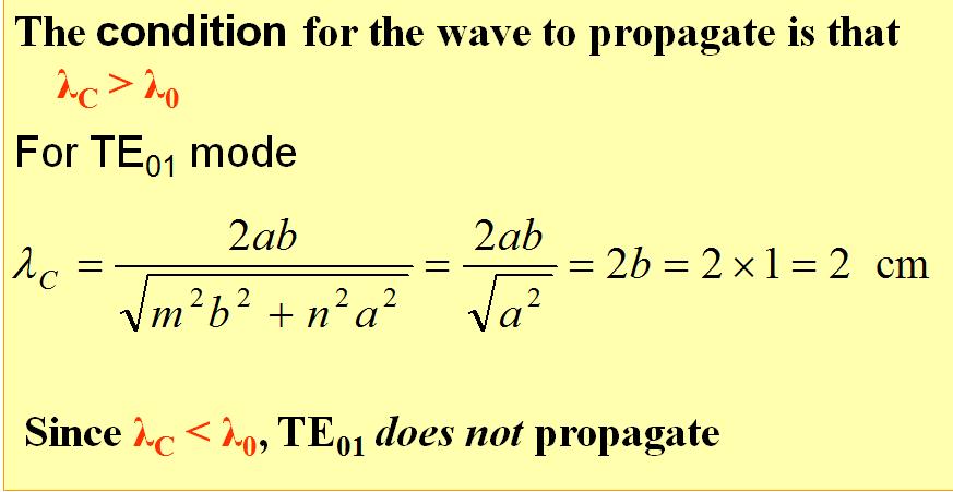
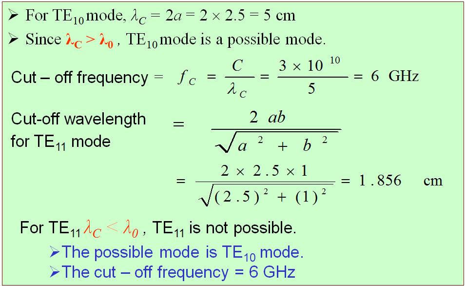
36 The circular waveguide is used in many special applications in microwave techniques. It has the advantage of greater power handling capacity and lower attenuation for a given cutoff wavelength. However, the disadvantage of somewhat greater size and weight. The polarization of the transmitted wave can be altered due to the minor irregularities of the wall surface of the circular guide, whereas the rectangular wave guide the polarization is fixed
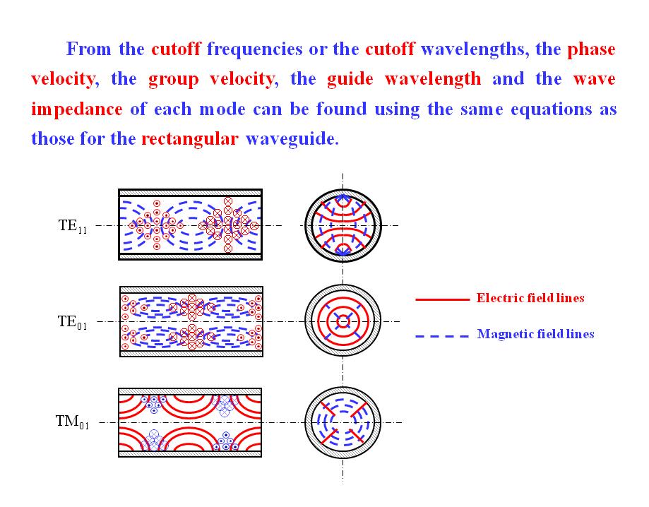
37 Description The wave of lowest frequency or the dominant mode in the circular waveguide is the TE 11 mode. The first subscript m indicates the number of full wave variations of the radial component of the electric field around the circumference of the waveguide. The second subscript n indicates the number of half wave variations across the diameter. The field configurations of TE 11 mode in the circular waveguide is shown in the diagram below
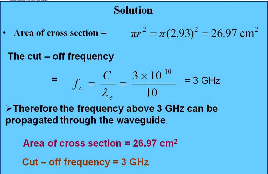
38
39 Applications of circular waveguide Rotating joints in radars to connect the horn antenna feeding a parabolic reflector (which must rotate for tracking) TE 01 mode suitable for long distance waveguide transmission above 10 GHz. Short and medium distance broad band communication (could replace / share coaxial and microwave links)
40 From the cutoff frequencies or the cutoff wavelengths, the phase velocity, the group velocity, the guide wavelength and the wave impedance of each mode can be found using the same equations as those for the rectangular waveguide.
41
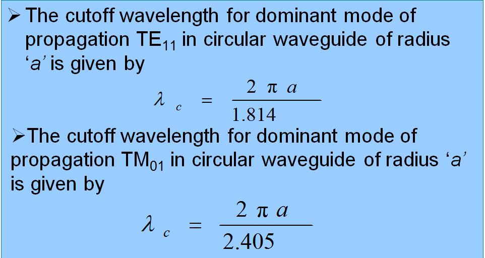
42 Cut Off Wavelength
43 Example 1
44
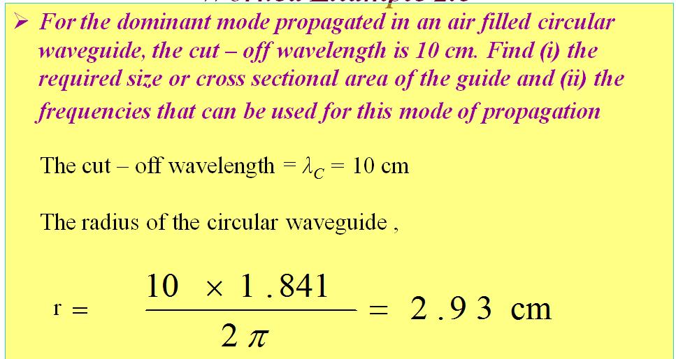
45 Example 2
46 Solution
47

48
ELEC4604. RF Electronics. Experiment 2
 ELEC4604 RF Electronics Experiment MICROWAVE MEASUREMENT TECHNIQUES 1. Introduction and Objectives In designing the RF front end of a microwave communication system it is important to appreciate that the
Waveguides GATE Problems
 Waveguides GATE Problems One Mark Questions. The interior of a 20 20 cm cm rectangular waveguide is completely 3 4 filled with a dielectric of r 4. Waves of free space wave length shorter than..can be
Photograph of the rectangular waveguide components
 Waveguides Photograph of the rectangular waveguide components BACKGROUND A transmission line can be used to guide EM energy from one point (generator) to another (load). A transmission line can support
Microwave and optical systems Introduction p. 1 Characteristics of waves p. 1 The electromagnetic spectrum p. 3 History and uses of microwaves and
 Microwave and optical systems Introduction p. 1 Characteristics of waves p. 1 The electromagnetic spectrum p. 3 History and uses of microwaves and optics p. 4 Communication systems p. 6 Radar systems p.
INTRODUCTION OF WAVEGUIDES
 INTRODUCTION OF WAVEGUIDES Under guidance of Joydeep Sengupta sir VNIT BT14ECE031 CHARAN SAI KATAKAM 1 INTRODUCTION TO WAVEGUIDES In a waveguide energy is transmitted in the form of electromagnetic waves
Waveguides. Metal Waveguides. Dielectric Waveguides
 Waveguides Waveguides, like transmission lines, are structures used to guide electromagnetic waves from point to point. However, the fundamental characteristics of waveguide and transmission line waves
COAXIAL / CIRCULAR HORN ANTENNA FOR A STANDARD
 COAXIAL / CIRCULAR HORN ANTENNA FOR 802.11A STANDARD Petr Všetula Doctoral Degree Programme (1), FEEC BUT E-mail: xvsetu00@stud.feec.vutbr.cz Supervised by: Zbyněk Raida E-mail: raida@feec.vutbr.cz Abstract:
EC Transmission Lines And Waveguides
 EC6503 - Transmission Lines And Waveguides UNIT I - TRANSMISSION LINE THEORY A line of cascaded T sections & Transmission lines - General Solution, Physical Significance of the Equations 1. Define Characteristic
ECSE 352: Electromagnetic Waves
 December 2008 Final Examination ECSE 352: Electromagnetic Waves 09:00 12:00, December 15, 2008 Examiner: Zetian Mi Associate Examiner: Andrew Kirk Student Name: McGill ID: Instructions: This is a CLOSED
ELECTROMAGNETIC WAVES AND ANTENNAS
 Syllabus ELECTROMAGNETIC WAVES AND ANTENNAS - 83888 Last update 20-05-2015 HU Credits: 4 Degree/Cycle: 1st degree (Bachelor) Responsible Department: Applied Phyisics Academic year: 1 Semester: 2nd Semester
EC6503 Transmission Lines and WaveguidesV Semester Question Bank
 UNIT I TRANSMISSION LINE THEORY A line of cascaded T sections & Transmission lines General Solution, Physicasignificance of the equations 1. Derive the two useful forms of equations for voltage and current
Lec7 Transmission Lines and waveguides (II)
") Lec7 Transmission Lines and waveguides (II) 3.4 CIRCULAR WAVEGUIDE A hollow, round metal pipe also supports TE and TM waveguide modes. we can derive the cylindrical components of the transverse fields
Lec7 Transmission Lines and waveguides (II) 3.4 CIRCULAR WAVEGUIDE A hollow, round metal pipe also supports TE and TM waveguide modes. we can derive the cylindrical components of the transverse fields
Unit 5 Waveguides P a g e 1
 Unit 5 Waveguides P a g e Syllabus: Introduction, wave equation in Cartesian coordinates, Rectangular waveguide, TE, TM, TEM waves in rectangular guides, wave impedance, losses in wave guide, introduction
USE OF MICROWAVES FOR THE DETECTION OF CORROSION UNDER INSULATION
 USE OF MICROWAVES FOR THE DETECTION OF CORROSION UNDER INSULATION R. E. JONES, F. SIMONETTI, M. J. S. LOWE, IMPERIAL COLLEGE, London, UK I. P. BRADLEY, BP Exploration and Production Company, Sunbury on
Rectangular waveguides
 Introduction Rectangular waveguides Waveguides are transmission lines commonly used in electronics, especially in higher frequency ranges like microwaves. A waveguide can be simply described as a metal
Keywords Cross-polarization, phasing length, return loss, multimode horn
 Volume 4, Issue, February 014 ISSN: 18X International Journal of Advanced Research in Computer Science and Software Engineering Research Paper Available online at: www.ijarcsse.com Cross Polarization Reduction
SRI VENKATESWARA COLLEGE OF ENGINEERING DEPARTMENT OF ELECTRONICS AND COMMUNICATION ENGINEERING Date : UNIVERSITY QUESTIONS AND ANSWERS
 SRI VENKATESWARA COLLEGE OF ENGINEERING DEPARTMENT OF ELECTRONICS AND COMMUNICATION ENGINEERING Date : 02.07.2015 UNIVERSITY QUESTIONS AND ANSWERS Subject : Transmission lines & Wave Guides Sub Code :
Practical Measurements of Dielectric Constant and Loss for PCB Materials at High Frequency
 8 th Annual Symposium on Signal Integrity PENN STATE, Harrisburg Center for Signal Integrity Practical Measurements of Dielectric Constant and Loss for PCB Materials at High Frequency Practical Measurements
2/18/ Transmission Lines and Waveguides 1/3. and Waveguides. Transmission Line A two conductor structure that can support a TEM wave.
 2/18/2009 3 Transmission Lines and Waveguides 1/3 Chapter 3 Transmission Lines and Waveguides First, some definitions: Transmission Line A two conductor structure that can support a TEM wave. Waveguide
UNIT - V WAVEGUIDES. Part A (2 marks)
") Part A (2 marks) UNIT - V WAVEGUIDES 1. What is the need for guide termination? (Nov / Dec 2011) To avoid reflection loss. The termination should provide a wave impedance equal to that of the transmission
Part A (2 marks) UNIT - V WAVEGUIDES 1. What is the need for guide termination? (Nov / Dec 2011) To avoid reflection loss. The termination should provide a wave impedance equal to that of the transmission
We are IntechOpen, the world s leading publisher of Open Access books Built by scientists, for scientists. International authors and editors
 We are IntechOpen, the world s leading publisher of Open Access books Built by scientists, for scientists 3,900 116,000 120M Open access books available International authors and editors Downloads Our
THE ELECTROMAGNETIC FIELD THEORY. Dr. A. Bhattacharya
 1 THE ELECTROMAGNETIC FIELD THEORY Dr. A. Bhattacharya The Underlying EM Fields The development of radar as an imaging modality has been based on power and power density It is important to understand some
EC TRANSMISSION LINES AND WAVEGUIDES TRANSMISSION LINES AND WAVEGUIDES
 TRANSMISSION LINES AND WAVEGUIDES UNIT I - TRANSMISSION LINE THEORY 1. Define Characteristic Impedance [M/J 2006, N/D 2006] Characteristic impedance is defined as the impedance of a transmission line measured
Fundamentals of Electromagnetics With Engineering Applications by Stuart M. Wentworth Copyright 2005 by John Wiley & Sons. All rights reserved.
 Figure 7-1 (p. 339) Non-TEM mmode waveguide structures include (a) rectangular waveguide, (b) circular waveguide., (c) dielectric slab waveguide, and (d) fiber optic waveguide. Figure 7-2 (p. 340) Cross
Aperture Antennas. Reflectors, horns. High Gain Nearly real input impedance. Huygens Principle
 Antennas 97 Aperture Antennas Reflectors, horns. High Gain Nearly real input impedance Huygens Principle Each point of a wave front is a secondary source of spherical waves. 97 Antennas 98 Equivalence
7. Experiment K: Wave Propagation
 7. Experiment K: Wave Propagation This laboratory will be based upon observing standing waves in three different ways, through coaxial cables, in free space and in a waveguide. You will also observe some
 VALLIAMMAI ENGINEERING COLLEGE SRM Nagar, Kattankulathur-603 203 DEPARTMENT OF ELECTRONICS AND COMMUNICATION ENGINEERING EC6503 TRANSMISSION LINES AND WAVEGUIDES YEAR / SEMESTER: III / V ACADEMIC YEAR:
TCET 2220/TC 410 Transmission Systems
 NEW YORK CITY COLLEGE OF TECHNOLOGY The City University of New York DEPARTMENT: SUBJECT CODE AND TITLE: Electrical and Telecommunications Engineering Technology TCET 2220/TC 410 Transmission Systems Required
Fiber Optic Communications Communication Systems
 INTRODUCTION TO FIBER-OPTIC COMMUNICATIONS A fiber-optic system is similar to the copper wire system in many respects. The difference is that fiber-optics use light pulses to transmit information down
Microwave Engineering
 Microwave Circuits 1 Microwave Engineering 1. Microwave: 300MHz ~ 300 GHz, 1 m ~ 1mm. a. Not only apply in this frequency range. The real issue is wavelength. Historically, as early as WWII, this is the
3. (a) Derive an expression for the Hull cut off condition for cylindrical magnetron oscillator. (b) Write short notes on 8 cavity magnetron [8+8]
![3. (a) Derive an expression for the Hull cut off condition for cylindrical magnetron oscillator. (b) Write short notes on 8 cavity magnetron [8+8]](/thumbs/73/68588725.jpg "3. (a) Derive an expression for the Hull cut off condition for cylindrical magnetron oscillator. (b) Write short notes on 8 cavity magnetron [8+8]") Code No: RR320404 Set No. 1 1. (a) Compare Drift space bunching and Reflector bunching with the help of Applegate diagrams. (b) A reflex Klystron operates at the peak of n=1 or 3 / 4 mode. The dc power
Code No: RR320404 Set No. 1 1. (a) Compare Drift space bunching and Reflector bunching with the help of Applegate diagrams. (b) A reflex Klystron operates at the peak of n=1 or 3 / 4 mode. The dc power
CHAPTER 2 MICROSTRIP REFLECTARRAY ANTENNA AND PERFORMANCE EVALUATION
 43 CHAPTER 2 MICROSTRIP REFLECTARRAY ANTENNA AND PERFORMANCE EVALUATION 2.1 INTRODUCTION This work begins with design of reflectarrays with conventional patches as unit cells for operation at Ku Band in
Γ L = Γ S =
 TOPIC: Microwave Circuits Q.1 Determine the S parameters of two port network consisting of a series resistance R terminated at its input and output ports by the characteristic impedance Zo. Q.2 Input matching
EMG4066:Antennas and Propagation Exp 1:ANTENNAS MMU:FOE. To study the radiation pattern characteristics of various types of antennas.
 OBJECTIVES To study the radiation pattern characteristics of various types of antennas. APPARATUS Microwave Source Rotating Antenna Platform Measurement Interface Transmitting Horn Antenna Dipole and Yagi
RAJIV GANDHI COLLEGE OF ENGINEERING AND TECHNOLOGY Kirumampakkam,Puducherry DEPARTMENT OF ELECTRONICS AND COMMUNICATION ENGINEERING
 RAJIV GANDHI COLLEGE OF ENGINEERING AND TECHNOLOGY Kirumampakkam,Puducherry-607402 DEPARTMENT OF ELECTRONICS AND COMMUNICATION ENGINEERING QUESTION BANK FOR EC T55 - TRANSMISSION LINES AND WAVEGUIDES G.LAXMINARAYANAN,
RF AND MICROWAVE ENGINEERING
 RF AND MICROWAVE ENGINEERING FUNDAMENTALS OF WIRELESS COMMUNICATIONS Frank Gustrau Dortmund University of Applied Sciences and Arts, Germany WILEY A John Wiley & Sons, Ltd., Publication Preface List of
R.K.YADAV. 2. Explain with suitable sketch the operation of two-cavity Klystron amplifier. explain the concept of velocity and current modulations.
 Question Bank DEPARTMENT OF ELECTRONICS AND COMMUNICATION SUBJECT- MICROWAVE ENGINEERING(EEC-603) Unit-III 1. What are the high frequency limitations of conventional tubes? Explain clearly. 2. Explain
DESIGN AND FABRICATION OF CAVITY RESONATORS
 &2@?%3 DESIGN AND FABRICATION OF CAVITY RESONATORS CHAPTER 3 DESIGN AND FABRICATION OFCAVITY RESONATORS 3.1 Introduction In the cavity perturbation techniques, generally rectangular or cylindrical waveguide
Monoconical RF Antenna
 Page 1 of 8 RF and Microwave Models : Monoconical RF Antenna Monoconical RF Antenna Introduction Conical antennas are useful for many applications due to their broadband characteristics and relative simplicity.
Useful general references for this experiment are Cheng [1], and Ramo et al [2].
![Useful general references for this experiment are Cheng [1], and Ramo et al [2].](/thumbs/74/70212276.jpg "Useful general references for this experiment are Cheng [1], and Ramo et al [2].") Experiment 7. Wave Propagation Updated RWH 21 August 2012 1 Aim In this experiment you will measure the radiation pattern of a half-wave dipole antenna, determine the resonant frequencies of a microwave
Experiment 7. Wave Propagation Updated RWH 21 August 2012 1 Aim In this experiment you will measure the radiation pattern of a half-wave dipole antenna, determine the resonant frequencies of a microwave
1. Evolution Of Fiber Optic Systems
 OPTICAL FIBER COMMUNICATION UNIT-I : OPTICAL FIBERS STRUCTURE: 1. Evolution Of Fiber Optic Systems The operating range of optical fiber system term and the characteristics of the four key components of
SUPPLEMENTARY INFORMATION
 A full-parameter unidirectional metamaterial cloak for microwaves Bilinear Transformations Figure 1 Graphical depiction of the bilinear transformation and derived material parameters. (a) The transformation
INSTITUTE OF AERONAUTICAL ENGINEERING Dundigal, Hyderabad ELECTRONICS AND COMMUNIACTION ENGINEERING QUESTION BANK
 INSTITUTE OF AERONAUTICAL ENGINEERING Dundigal, Hyderabad - 500 04 ELECTRONICS AND COMMUNIACTION ENGINEERING QUESTION BANK Course Name : Antennas and Wave Propagation (AWP) Course Code : A50418 Class :
Hours / 100 Marks Seat No.
 17656 16117 3 Hours / 100 Seat No. Instructions (1) All Questions are Compulsory. (2) Answer each next main Question on a new page. (3) Assume suitable data, if necessary. (4) Use of Non-programmable Electronic
Introduction: Planar Transmission Lines
 Chapter-1 Introduction: Planar Transmission Lines 1.1 Overview Microwave integrated circuit (MIC) techniques represent an extension of integrated circuit technology to microwave frequencies. Since four
Wave & Electromagnetic Spectrum Notes
 Wave & Electromagnetic Spectrum Notes December 17, 2011 I.) Properties of Waves A) Wave: A periodic disturbance in a solid, liquid or gas as energy is transmitted through a medium ( Waves carry energy
Lecture #3 Microstrip lines
 November 2014 Ahmad El-Banna Benha University Faculty of Engineering at Shoubra Post-Graduate ECE-601 Active Circuits Lecture #3 Microstrip lines Instructor: Dr. Ahmad El-Banna Agenda Striplines Forward
PRINCIPLES OF RADAR. By Members of the Staff of the Radar School Massachusetts Institute of Technology. Third Edition by J.
 PRINCIPLES OF RADAR By Members of the Staff of the Radar School Massachusetts Institute of Technology Third Edition by J. Francis Reintjes ASSISTANT PBOFESSOR OF COMMUNICATIONS MASSACHUSETTS INSTITUTE
Dielectric Circular Waveguide Loaded with Dielectric Material
 Dielectric Circular Waveguide Loaded with Dielectric Material Dimple N. Agrawal 1, Raj Hakani 2 PG Student, Dept. of Electronics and Communication, Silver Oak College of Engineering and Technology, Ahmedabad,
A NOVEL DUAL-BAND PATCH ANTENNA FOR WLAN COMMUNICATION. E. Wang Information Engineering College of NCUT China
 Progress In Electromagnetics Research C, Vol. 6, 93 102, 2009 A NOVEL DUAL-BAND PATCH ANTENNA FOR WLAN COMMUNICATION E. Wang Information Engineering College of NCUT China J. Zheng Beijing Electro-mechanical
EC ANTENNA AND WAVE PROPAGATION
 EC6602 - ANTENNA AND WAVE PROPAGATION FUNDAMENTALS PART-B QUESTION BANK UNIT 1 1. Define the following parameters w.r.t antenna: i. Radiation resistance. ii. Beam area. iii. Radiation intensity. iv. Directivity.
KULLIYYAH OF ENGINEERING
 KULLIYYAH OF ENGINEERING DEPARTMENT OF ELECTRICAL & COMPUTER ENGINEERING ANTENNA AND WAVE PROPAGATION LABORATORY (ECE 4103) EXPERIMENT NO 3 RADIATION PATTERN AND GAIN CHARACTERISTICS OF THE DISH (PARABOLIC)
Fiber Optic Communication Systems. Unit-04: Theory of Light. https://sites.google.com/a/faculty.muet.edu.pk/abdullatif
 Unit-04: Theory of Light https://sites.google.com/a/faculty.muet.edu.pk/abdullatif Department of Telecommunication, MUET UET Jamshoro 1 Limitations of Ray theory Ray theory describes only the direction
COMPARATIVE ANALYSIS BETWEEN CONICAL AND GAUSSIAN PROFILED HORN ANTENNAS
 Progress In Electromagnetics Research, PIER 38, 147 166, 22 COMPARATIVE ANALYSIS BETWEEN CONICAL AND GAUSSIAN PROFILED HORN ANTENNAS A. A. Kishk and C.-S. Lim Department of Electrical Engineering The University
CHAPTER 5 THEORY AND TYPES OF ANTENNAS. 5.1 Introduction
 CHAPTER 5 THEORY AND TYPES OF ANTENNAS 5.1 Introduction Antenna is an integral part of wireless communication systems, considered as an interface between transmission line and free space [16]. Antenna
1. What are the applications of loop antenna? (May2011) 2. Define Pattern Multiplication (May2011)
 2. Define Pattern Multiplication (May2011)") UNIT-II WIRE ANTENNAS AND ANTENNA ARRAYS 1. What are the applications of loop antenna? (May2011) 2. Define Pattern Multiplication (May2011) 3. A uniform linear array contains 50 isotropic radiation with
UNIT-II WIRE ANTENNAS AND ANTENNA ARRAYS 1. What are the applications of loop antenna? (May2011) 2. Define Pattern Multiplication (May2011) 3. A uniform linear array contains 50 isotropic radiation with
(i) Determine the admittance parameters of the network of Fig 1 (f) and draw its - equivalent circuit.
 Determine the admittance parameters of the network of Fig 1 (f) and draw its - equivalent circuit.") I.E.S-(Conv.)-1995 ELECTRONICS AND TELECOMMUNICATION ENGINEERING PAPER - I Some useful data: Electron charge: 1.6 10 19 Coulomb Free space permeability: 4 10 7 H/m Free space permittivity: 8.85 pf/m Velocity
I.E.S-(Conv.)-1995 ELECTRONICS AND TELECOMMUNICATION ENGINEERING PAPER - I Some useful data: Electron charge: 1.6 10 19 Coulomb Free space permeability: 4 10 7 H/m Free space permittivity: 8.85 pf/m Velocity
Dual-band Antenna Feed Solution for 5G. A dual-band coaxial- and waveguide fed antenna feed for reflector LUKAS MARED
 Dual-band Antenna Feed Solution for 5G A dual-band coaxial- and waveguide fed antenna feed for reflector antenna systems Master s thesis in Wireless, photonics and space engineering LUKAS MARED Department
MICROWAVE WAVEGUIDES and COAXIAL CABLE
 MICROWAVE WAVEGUIDES and COAXIAL CABLE In general, a waveguide consists of a hollow metallic tube of arbitrary cross section uniform in extent in the direction of propagation. Common waveguide shapes are
Keysight Technologies Techniques for Advanced Cable Testing
 Keysight Technologies Techniques for Advanced Cable Testing Using FieldFox handheld analyzers Application Note Transmission lines are used to guide the flow of energy from one point to another. Line types
FINAL EXAM 12/12/03 EECS FALL 2003
 EECS 412 - FALL 2003 FINAL EXAM 12/12/03 NAME: CWRUnet e-mail address: IMPORTANT INFORMATION: 1. All questions are worth the same. 2. Exam is due December 12 th at 12 noon in Glennan 518. Possible 1. 10
Waveguide Calibration with Copper Mountain Technologies VNA
 Clarke & Severn Electronics Ph: +612 9482 1944 BUY NOW www.cseonline.com.au Introduction Waveguide components possess certain advantages over their counterpart devices with co-axial connectors: they can
MICROWAVE AND RADAR LAB (EE-322-F) LAB MANUAL VI SEMESTER
 LAB MANUAL VI SEMESTER") 1 MICROWAVE AND RADAR LAB (EE-322-F) MICROWAVE AND RADAR LAB (EE-322-F) LAB MANUAL VI SEMESTER RAO PAHALD SINGH GROUP OF INSTITUTIONS BALANA(MOHINDERGARH)123029 Department Of Electronics and Communication
1 MICROWAVE AND RADAR LAB (EE-322-F) MICROWAVE AND RADAR LAB (EE-322-F) LAB MANUAL VI SEMESTER RAO PAHALD SINGH GROUP OF INSTITUTIONS BALANA(MOHINDERGARH)123029 Department Of Electronics and Communication
Simulation and manufacturing of a miniaturized Exponential UWB TEM horn antenna for UWB Radar applications
 Journal of Microwaves, Optoelectronics and Electromagnetic Applications, Vol. 12, No. 2, December 2013 655 Simulation and manufacturing of a miniaturized Exponential UWB TEM horn antenna for UWB Radar
Waves, Wavelength, Frequency and. Bands. Al Penney VO1NO
 Waves, Wavelength, Frequency and Bands Objective On completion, you should be able to: Define Frequency, Wavelength, Band; Perform simple calculations involving frequency and wavelength; and Be familiar
Antennas 1. Antennas
 Antennas Antennas 1! Grading policy. " Weekly Homework 40%. " Midterm Exam 30%. " Project 30%.! Office hour: 3:10 ~ 4:00 pm, Monday.! Textbook: Warren L. Stutzman and Gary A. Thiele, Antenna Theory and
Projects in microwave theory 2009
 Electrical and information technology Projects in microwave theory 2009 Write a short report on the project that includes a short abstract, an introduction, a theory section, a section on the results and
ECE 3065: Electromagnetic Applications Final Exam (Spring 2004)
") Name: GTID: ECE 3065: Electromagnetic Applications Final Exam (Spring 2004) Please read all instructions before continuing with the test. This is a closed notes, closed book, closed calculator, closed
Name: GTID: ECE 3065: Electromagnetic Applications Final Exam (Spring 2004) Please read all instructions before continuing with the test. This is a closed notes, closed book, closed calculator, closed
A Mode Based Model for Radio Wave Propagation in Storm Drain Pipes
 PIERS ONLINE, VOL. 4, NO. 6, 008 635 A Mode Based Model for Radio Wave Propagation in Storm Drain Pipes Ivan Howitt, Safeer Khan, and Jumanah Khan Department of Electrical and Computer Engineering The
ANTENNA INTRODUCTION / BASICS
 ANTENNA INTRODUCTION / BASICS RULES OF THUMB: 1. The Gain of an antenna with losses is given by: 2. Gain of rectangular X-Band Aperture G = 1.4 LW L = length of aperture in cm Where: W = width of aperture
A New TEM Horn Antenna Designing Based on Plexiglass Antenna Cap
 Journal of Applied Science and Engineering, Vol. 21, No. 3, pp. 413 418 (2018) DOI: 10.6180/jase.201809_21(3).0012 A New TEM Horn Antenna Designing Based on Plexiglass Antenna Cap Lin Teng and Jie Liu*
DEPARTMENT OF ELECTRONICS AND COMMUNICATION ENGINEERING SUBJECT CODE: EC 1305 SUBJECT: TRANSMISSION LINES AND WAVEGUIDES (FOR FIFTH SEMESTER ECE)
") DEPARTMENT OF ELECTRONICS AND COMMUNICATION ENGINEERING SUBJECT CODE: EC 1305 SUBJECT: TRANSMISSION LINES AND WAVEGUIDES (FOR FIFTH SEMESTER ECE) TWO MARKS QUESTIONS UNIT I-TRANSMISSION LINE THEORY 1.Define
DEPARTMENT OF ELECTRONICS AND COMMUNICATION ENGINEERING SUBJECT CODE: EC 1305 SUBJECT: TRANSMISSION LINES AND WAVEGUIDES (FOR FIFTH SEMESTER ECE) TWO MARKS QUESTIONS UNIT I-TRANSMISSION LINE THEORY 1.Define
Chapter 15: Radio-Wave Propagation
 Chapter 15: Radio-Wave Propagation MULTIPLE CHOICE 1. Radio waves were first predicted mathematically by: a. Armstrong c. Maxwell b. Hertz d. Marconi 2. Radio waves were first demonstrated experimentally
Design of a prime-focus feed with backward radiation
 Design of a prime-focus feed with backward radiation Libor SLÁMA 1, Rastislav GALUŠČÁK - OM6AA 1, Pavel HAZDRA 1 1 Dept. of Electromagnetic Field, Czech Technical University, Technická 2, 166 27 Praha,
Chapter 4 The RF Link
 Chapter 4 The RF Link The fundamental elements of the communications satellite Radio Frequency (RF) or free space link are introduced. Basic transmission parameters, such as Antenna gain, Beamwidth, Free-space
ELEC4604. RF Electronics. Experiment 1
 ELEC464 RF Electronics Experiment ANTENNA RADATO N PATTERNS. ntroduction The performance of RF communication systems depend critically on the radiation characteristics of the antennae it employs. These
Department of Electrical Engineering University of North Texas
 Name: Shabuktagin Photon Khan UNT ID: 10900555 Instructor s Name: Professor Hualiang Zhang Course Name: Antenna Theory and Design Course ID: EENG 5420 Email: khan.photon@gmail.com Department of Electrical
PRIME FOCUS FEEDS FOR THE COMPACT RANGE
 PRIME FOCUS FEEDS FOR THE COMPACT RANGE John R. Jones Prime focus fed paraboloidal reflector compact ranges are used to provide plane wave illumination indoors at small range lengths for antenna and radar
Electromagnetic Wave Analysis of Waveguide and Shielded Microstripline 1 Srishti Singh 2 Anupma Marwaha
 Electromagnetic Wave Analysis of Waveguide and Shielded Microstripline 1 Srishti Singh 2 Anupma Marwaha M.Tech Research Scholar 1, Associate Professor 2 ECE Deptt. SLIET Longowal, Punjab-148106, India
Cut-off of Resonant Modes in Truncated Conical Cavities
 Cut-off of Resonant Modes in Truncated Conical Cavities José J. Rodal, Ph.D. June 2015 Although the fact that a truncated conical cavity displays an absence of sharp cut-off frequencies has been remarked
APPLIED ELECTROMAGNETICS: EARLY TRANSMISSION LINES APPROACH
 APPLIED ELECTROMAGNETICS: EARLY TRANSMISSION LINES APPROACH STUART M. WENTWORTH Auburn University IICENTBN Nlfll 1807; WILEY 2 OO 7 ; Ttt^TlLtftiTTu CONTENTS CHAPTER1 Introduction 1 1.1 1.2 1.3 1.4 1.5
Antenna & Propagation. Basic Radio Wave Propagation
 For updated version, please click on http://ocw.ump.edu.my Antenna & Propagation Basic Radio Wave Propagation by Nor Hadzfizah Binti Mohd Radi Faculty of Electric & Electronics Engineering hadzfizah@ump.edu.my
Design and Implementation of Quasi Planar K-Band Array Antenna Based on Travelling Wave Structures
 Design and Implementation of Quasi Planar K-Band Array Antenna Based on Travelling Wave Structures Zunnurain Ahmad This thesis is presented as part of Degree of Master of Science in Electrical Engineering
UWB leaky lens antenna design and simulation for waveguide measurements
 Master s Thesis UWB leaky lens antenna design and simulation for waveguide measurements By Liu Jin Department of Electrical and Information Technology Faculty of Engineering, LTH, Lund University SE-221
EFFECT ON PERFORMANCE CHARACTERISTICS OF RECTANGULAR PATCH ANTENNA WITH VARYING HEIGHT OF DIELECTRIC COVER
 International Journal of Power Control Signal and Computation (IJPCSC) Vol. 2 No. 1 ISSN : 0976-268X EFFECT ON PERFORMANCE CHARACTERISTICS OF RECTANGULAR PATCH ANTENNA WITH VARYING HEIGHT OF DIELECTRIC
Chapter 41 Deep Space Station 13: Venus
 Chapter 41 Deep Space Station 13: Venus The Venus site began operation in Goldstone, California, in 1962 as the Deep Space Network (DSN) research and development (R&D) station and is named for its first
An Introduction to Antennas
 May 11, 010 An Introduction to Antennas 1 Outline Antenna definition Main parameters of an antenna Types of antennas Antenna radiation (oynting vector) Radiation pattern Far-field distance, directivity,
I.E.S-(Conv.)-1996 Some useful data:
-1996 Some useful data:") I.E.S-(Conv.)-1996 ELECTRONICS AND TELECOMMUNICATION ENGINEERING PAPER - I Time allowed: 3 Hours Maximum Marks : 200 Candidates should attempt question ONE which is compulsory and any FOUR of the remaining
I.E.S-(Conv.)-1996 ELECTRONICS AND TELECOMMUNICATION ENGINEERING PAPER - I Time allowed: 3 Hours Maximum Marks : 200 Candidates should attempt question ONE which is compulsory and any FOUR of the remaining
Notes 21 Introduction to Antennas
 ECE 3317 Applied Electromagnetic Waves Prof. David R. Jackson Fall 018 Notes 1 Introduction to Antennas 1 Introduction to Antennas Antennas An antenna is a device that is used to transmit and/or receive
MEASUREMENT OF COMPLEX PERMITTIVITY AND COMPLEX PERMEABILITY OF MATERIALS. H. Alenkowicz*, B. Levitas**
 MEAUREMEN OF COMPLEX PERMIIVIY AND COMPLEX PERMEABILIY OF MAERIAL H. Alenkowicz*, B. Levitas** ime Domain measurement of complex permittivity and complex permeability in the 8 to 18 GHz frequency band
Fiber Optic Communication Systems. Unit-05: Types of Fibers. https://sites.google.com/a/faculty.muet.edu.pk/abdullatif
 Unit-05: Types of Fibers https://sites.google.com/a/faculty.muet.edu.pk/abdullatif Department of Telecommunication, MUET UET Jamshoro 1 Optical Fiber Department of Telecommunication, MUET UET Jamshoro
KINGS COLLEGE OF ENGINEERING. DEPARTMENT OF ELECTRONICS AND COMMUNICATION ENGINEERING Academic Year (Even Sem) QUESTION BANK (AUTT-R2008)
 QUESTION BANK (AUTT-R2008)") KINGS COLLEGE OF ENGINEERING DEPARTMENT OF ELECTRONICS AND COMMUNICATION ENGINEERING Academic Year 2012-2013(Even Sem) QUESTION BANK (AUTT-R2008) SUBJECT CODE /NAME: EC 1352 / ANTENNEA AND WAVE PROPAGATION
KINGS COLLEGE OF ENGINEERING DEPARTMENT OF ELECTRONICS AND COMMUNICATION ENGINEERING Academic Year 2012-2013(Even Sem) QUESTION BANK (AUTT-R2008) SUBJECT CODE /NAME: EC 1352 / ANTENNEA AND WAVE PROPAGATION
Impedance Matching For L-Band & S- Band Navigational Antennas
 Impedance Matching For L-Band & S- Band Navigational Antennas 1 Jigar A Soni, 2 Anil K Sisodia 1 PG student, 2 Professor. Electronics & Communication Department, L.J.Institute of technology, Ahmedabad,
L-BAND COPLANAR SLOT LOOP ANTENNA FOR INET APPLICATIONS
 L-BAND COPLANAR SLOT LOOP ANTENNA FOR INET APPLICATIONS Jeyasingh Nithianandam Electrical and Computer Engineering Department Morgan State University, 500 Perring Parkway, Baltimore, Maryland 5 ABSTRACT
Antennas and Propagation. Chapter 4: Antenna Types
 Antennas and Propagation : Antenna Types 4.4 Aperture Antennas High microwave frequencies Thin wires and dielectrics cause loss Coaxial lines: may have 10dB per meter Waveguides often used instead Aperture
CHAPTER 3 METHODOLOGY AND SOFTWARE TOOLS
 CHAPTER 3 METHODOLOGY AND SOFTWARE TOOLS Microstrip Patch Antenna Design In this chapter, the procedure for designing of a rectangular microstrip patch antenna is described. The proposed broadband rectangular
ANTENNAS AND WAVE PROPAGATION EC602
 ANTENNAS AND WAVE PROPAGATION EC602 B.Tech Electronics & Communication Engineering, Semester VI INSTITUTE OF TECHNOLOGY NIRMA UNIVERSITY 1 Lesson Planning (L-3,P-2,C-4) Chapter No. Name Hours 1. Basic
Antenna Fundamentals
 HTEL 104 Antenna Fundamentals The antenna is the essential link between free space and the transmitter or receiver. As such, it plays an essential part in determining the characteristics of the complete
Localization and Identifying EMC interference Sources of a Microwave Transmission Module
 Localization and Identifying EMC interference Sources of a Microwave Transmission Module Ph. Descamps 1, G. Ngamani-Njomkoue 2, D. Pasquet 1, C. Tolant 2, D. Lesénéchal 1 and P. Eudeline 2 1 LaMIPS, Laboratoire
University of KwaZulu-Natal
 University of KwaZulu-Natal School of Engineering Electrical, Electronic & Computer Engineering Instructions to Candidates: UNIVERSITY EXAMINATIONS DECEMBER 2016 ENEL3EM: EM THEORY Time allowed: 2 hours