Geology 228/378 Environmental Geophysics Lecture 10. Electromagnetic Methods (EM) I And frequency EM (FEM)
|
|
|
- Elisabeth Bishop
- 6 years ago
- Views:
Transcription
1 Geology 228/378 Environmental Geophysics Lecture 10 Electromagnetic Methods (EM) I And frequency EM (FEM)
2 Lecture Outline Introduction Principles Systems and Methods Case Histories
3 Introduction Many EM systems available EM has a wide application Mineral exploration Ground water contamination Salt water intrusion Mapping geology and soil Locating buried objects ( pipes, barrels, tanks, walls) Archeology Locating frozen permafrost Locating Gravel Locating cavities (caves, abandon mines)
4 Advantages relative to other electrical methods EM is based on induction Does not require electrodes in ground. Faster surveys over larger areas. Can be used from: Land, Airborne, seaborne. Downhole
5 Disadvantages EM is based on induction Fixed depth of investigation depending on frequency used and Tx-Rx separation. More sophisticated interpretation skill.
6 Types of EM Systems 1. TEM vs FEM Time-domain (TEM) Measurements as a function of time Frequency-domain (FEM) Measurements at one or more frequencies 2. Passive vs Active Passive: Uses natural ground signals (e.g., magnetotellurics), sources are lightning, magnetosphere activities, etc. Active: use transmitter to induce ground current Near-field ( ground conductivity meters) Far-field (VLF uses very low frequency signals used to communicate with submarines ).
7 Types of EM Systems Inductive Small loop Most FEM (EM 31, EM 34, etc.) but some TEM Most widely used in environmental investigations Large loop (5 m to 100 m loops) Many TEM systems ( esp. airborne) Mineral exploration, environmental investigations Plane wave (VLF, Magnetotelluric) Mineral exploration, deep geologic structure
 Pole, two small coils, one transmitter")

8 Small Loop Systems FEM ( frequency domain EM) Pole, two small coils, one transmitter and one receiver, separated by a constant spacing moved along a survey transect. Geonics EM31

9 Small loop systems Two coils( transmitter and receiver) connected by wires that permit several different separations and configurations Geonics EM34
10 Loop configurations HCP (horizontal co-planer) VCP (vertical co-planer) VCA (vertical Coaxial) Others


11 How does EM Induction work? Magnetism Magnetic lines of force ( owing to alignment of atoms, the H-field)

12 EM Theory (1) In 1820, Hans Oersted discovered that a magnetic compass could be deflected from its resting position if a wire carrying electric current were placed near the compass. Magnetic Field Any wire in which an electric current is flowing is surrounded by an invisible force field called a magnetic field. This phenomenon is described as the Ampere s law. H = Idl r 2πr 0 2

13 EM Theory (2) Electromagnetism The term electromagnetism is defined as the production of a magnetic field by current flowing in a conductor. Coiling a current-carrying conductor around a core material that can be easily magnetized, such as iron, can form an electromagnet. The magnetic field will be concentrated in the core. This arrangement is called a solenoid. The more turns we wrap on this core, the stronger the electromagnet and the stronger the magnetic lines of force become.
.")
14 Right hand being used to find the polarity of the magnetic field around a coil of wire (the thumb is pointing towards the North pole) when you know the direction of the current around the coil (the fingers are wrapping around the coil in the same direction as the current). Notice that all of the lines of force pass through the center of the coil material, regardless of how they extend outside the coil of wire.
15 EM Theory (3) The magnetic field that surrounds a currentcarrying conductor is made up of concentric lines of force. The strength of these circular lines of force gets progressively smaller the further away from the conductor. if a stronger current is made to flow through the conductor, the magnetic lines of force become stronger. the strength of the magnetic field is directly proportional to the current that flows through the conductor. H = Idl r 2πr 2 0
16 EM Theory (4) The term field intensity is used to describe the strength of the magnetic field. We have now seen that if electrical current is flowing in a conductor, there is an associated magnetic field created around the wire. In a similar manner, if we move a wire inside a magnetic field there will be an electrical current that will be generated in the wire. This is described as the Faraday s law.
17 EM Theory (5) Induction Current is produced in a conductor when it is moved through a magnetic field because the magnetic lines of force are applying a force on the free electrons in the conductor and causing them to move. The direction that the induced current flows is determined by the direction of the lines of force and by the direction the wire is moving in the field. If an AC current is fed through a piece of wire, the electromagnetic field that is produced is constantly growing and shrinking due to the constantly changing current in the wire. This growing and shrinking magnetic field can induce electrical current in another wire that is held close to the first wire. The current in the second wire will also be AC and in fact will look very similar to the current flowing in the first wire.

18 If we move a wire in a magnetic field, the movement will create a current in the wire. Essentially, as we cut through the magnetic lines of force, we cause the electrons to move in the wire. The faster we move the wire, the more current we generate. Again, the right hand helps determine which way the current is going to flow. If you hold your hand as is shown in the diagram below, point your index finger in the direction of the magnetic lines of force (N to S...) and your thumb in the direction of the movement of the wire relative to the lines of force, your middle finger will point in the direction of the current.
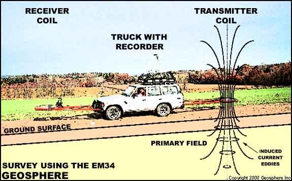
19 Principles of EM Surveying Generate EM field by passing an AC through a wire coil ( transmitter) EM field propagates above and below ground. If there is conductive material in ground, magnetic component of the EM wave induces eddy currents (AC) in conductor. The eddy currents produce a secondary EM field which is detected by the receiver. The receiver also detects the primary field (the resultant field is a combination of primary and secondary which differs from the primary field in phase and amplitude). After compensating for the primary field (which can be computed from the relative positions and orientations of the coils), both the magnitude and relative phase of the secondary field can be measured. The difference in the resultant field from the primary provides information about the geometry, size and electrical properties of the subsurface conductor.
20 Secondary field can be converted to components in-phase and 90 out of phase with the transmitted field. The out-of-phase (or quadrature-phase ) component, using certain simplifying assumptions, can be converted to a measure of apparent ground conductivity. The in-phase component, while generally not responsive to changes in bulk conductivity, is especially responsive to discrete, highly-conductive bodies such as metal objects. The apparent conductivity measurement is the average conductivity of one or more layers in the ground in the proximity of the instrument, to a depth of investigation dependent on the coil spacing, orientation, operating frequency of the instrument, and the individual conductivity of each ground layer.
21
22 Depth of penetration Function of frequency and ground EC Skin depth (SD): amplitude of plane wave has decreased to 1/e or 37% relative to the initial amplitude (Ao) or Az = Ao e -1 SD = (2/ωσ).5 = 503(fσ).5 ω = 2πf, f = frequency (HZ), σ = EC (S/m)
23 FEM: General Principles of EM Operation Transmitter produces continuous EM field, secondary field is determined by nulling the primary field ( need two coils) TEM Primary field is applied in pulses ( 20-40ms) then switched off and the secondary field measured ( same coil can be transmitter and receiver, more often large coil on ground and move small coil around)
24 Factors influencing subsurface electrical conductivity Mineralogy Clays more conductive (relates to CEC) Moisture content Porosity EC of the subsurface water Stratigraphy Structure Temporal Changes in soil EC due to soil moisture change, water table changes, soils are frozen ( Low EC), soil temperature changes (lowers EC of soil water). Adding or subtracting soluble constituents (contaminants) source strength variations and directions of ground water flow. Presence of NAPLs
25 EC = 1/R crystalline rock 10 5 ohm-m <=> 10-5 S/m = 10-2 ms/m = 10µS/m = 0.1 µs/cm Clay soil 10 ohm-m <=> 0.1 S/m = 10 2 ms/m = 10 5 µs/m = 10 3 µs/cm Water EC = TDS(mg/l)/.5
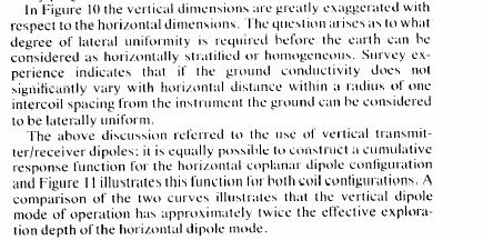
26 Relative Response φ Horizontal dipole Vertical dipole z dz z = normalized depth: =depth/(inter-coil spacing); φ= relative contribution to Hs from a thin layer at depth z; For Vertical dipole, max contribution of layer is at.4z, not sensitive to surface conditions.

27 Layered Earth Models 25% of Hs below 2z or 25% of σ below 2z
28

29 Using different spacing and configurations in Modeling
30 Advantages Relative to DC Resistivity Less sensitive to conditions at surface of ground No problems with coupling to ground since it is inductive. Perform simple multilayered earth calcs. Easy and Rapid Measurements On plane and boat
31 Disadvantages relative to DC resistivity Limited dynamic range ( mmhos/m) Low EC: can t readily induce current High EC: EC not linear function of H Setting instrument to zero Ideally needs to suspending in free space Reality set to zero rel. prevailing conditions Limited vertical sounding capability
32 Survey Instruments
33

34 EM 31 GEONICS
35 EM 31 Characteristics Intercoil spacing of 3.7 m. Effective depth of exploration = 6 m (pole horizontal), 3 m (pole vertical) Detect layering by rasing and lower instrument. Procedure: Lay out survey line with a measuring tape, walk to measurement location, turn on transmitter read apparent conductivity ( in millimhos/m)

36 EM 34 GEONICS
37 EM 34 Characteristics Two person instrument Intercoil spacing of 10, 20 and 40M Intercoil spacing is measured electronically, read meter to accurately set spacing.
38 Survey procedure: (1) Lay out survey line with tape (2) Transmitter operator stops at measurement station. (3) The receiver operator moves coil forward and back until his meter indicates correct intercoil spacing. (4) The transmitter operator reads apparent conductivity in millimhos/m. (5) Takes sec per reading. (6) Normally survey in horizontal dipole mode ( coils vertical) which is less subject to coil misalignment. (7) you can also use vertical dipole ( coils horizontal).
39 EM 31 and 34 relation of H to σ Instruments are designed to operate at: Specific fixed frequencies, Fixed inter-coil spacings and at Fixed Hp Given above instrument constraints: σ directly proportional to Hs/Hp Depth of penetration primarily function of instrument configuration

40 The basic GEM-3 Package consists of: a 64-cm diameter sensing head, handle boom, console and display unit, and battery charger. Standard software includes WinGEMv3, Windows-based operation software. The optional 96-cm head, due to its size, must be mounted on a cart. Programmable Operation Bandwidth 30 Hz to 24 khz Frequency domain Single, multiple, or stepping frequencies Maximum sampling rate Approx. 15 Hz at one frequency or 8 Hz at 10 frequencies
41


42 Airborne Surveying GEOTEM T and R separations m
43


44 The World s Most Advanced HEM System Redefining Helicopter Electromagnetics Reliable, Repeatable, Precise 3D RESISTIVITY Unsurpassed Horizontal and Vertical RESOLUTION RESOLVE your Questions. SOLVE your Exploration Problems RESOLVE -a unique six frequency system with horizontal coplanar coils capable of measuring the EM response at 400Hz, 1500Hz, 6400Hz, 25kHz, 100kHz, and one coaxial coil pair at 3300Hz. Designed for the calculation of 3D earth resitivity models, overburden thickness, layered inversions, EM-derived susceptibility and other advanced products. Horizontal coplanar coil pairs combined with a coaxial coil pair are excellent for interpreting conductors. RESOLVE is fully digital, offering lower noise and real-time signal processing as well as internal calibration coils for automatic phase and gain calibration in the air - out of ground effect - resulting in higher accuracy and reduced drift. RESOLVE offers the exploration professional horizontal and vertical resolution unparalleled in an airborne EM system. Multiple coplanar coils are exceptional for mapping horizontal layers.

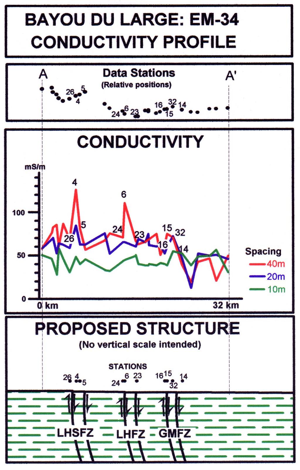
45 Saltwater intrusion along the Baton Rouge Fault (Kuecher, 2004)
46
47 Modeling 3 Layer Earth
48

49 GEONICS EM 61
Geology 228 Applied Geophysics Lecture 10. Electromagnetic Methods (EM) (Reynolds, Ch. 10, 11)
 (Reynolds, Ch. 10, 11)") Geology 228 Applied Geophysics Lecture 10 Electromagnetic Methods (EM) (Reynolds, Ch. 10, 11) Lecture Outline Introduction Principles Systems and Methods (FDEM & TDEM) Case Histories APPLICATIONS 1. Mineral
Geology 228 Applied Geophysics Lecture 10 Electromagnetic Methods (EM) (Reynolds, Ch. 10, 11) Lecture Outline Introduction Principles Systems and Methods (FDEM & TDEM) Case Histories APPLICATIONS 1. Mineral
Electromagnetic Induction
 Electromagnetic Induction Recap the motivation for using geophysics We have problems to solve Slide 1 Finding resources Hydrocarbons Minerals Ground Water Geothermal Energy SEG Distinguished Lecture slide
Old & New? INTRODUCTION. The Best Proximal Geophysical Detector Ever!
 Measuring Soil Conductivity with Geonics Limited Electromagnetic Geophysical Instrumentation INTRODUCTION This presentation will briefly discuss the principles of operation and the practical applications
Here the goal is to find the location of the ore body, and then evaluate its size and depth.
 Geophysics 223 March 2009 D3 : Ground EM surveys over 2-D resistivity models D3.1 Tilt angle measurements In D2 we discussed approaches for mapping terrain conductivity. This is appropriate for many hydrogeology
In this lecture. Electromagnetism. Electromagnetism. Oersted s Experiment. Electricity & magnetism are different aspects of the same basic phenomenon:
 In this lecture Electromagnetism Electromagnetic Effect Electromagnets Electromechanical Devices Transformers Electromagnetic Effect Electricity & magnetism are different aspects of the same basic phenomenon:
HELICOPTER-BORNE GEOPHYSICAL SURVEY SYSTEMS
 HELICOPTER-BORNE GEOPHYSICAL SURVEY SYSTEMS APPLICATIONS: base & precious metals exploration diamondiferous kimberlite exploration geological mapping mapping of fault zones for engineering and mining applications
Electrical Resistivity Imaging
 Approved for Public Release; Distribution Unlimited Electrical Resistivity Imaging David Hull US Army Research Lab hull@arl.army.mil 17 Jun 2009 ARL Workshop on Personnel, Vehicle, and Tunnel Detection
Technical Note TN-30 WHY DOESN'T GEONICS LIMITED BUILD A MULTI-FREQUENCY EM31 OR EM38? J.D. McNeill
 Tel: (905) 670-9580 Fax: (905) 670-9204 GEONICS LIMITED E-mail:geonics@geonics.com 1745 Meyerside Dr. Unit 8 Mississauaga, Ontario Canada L5T 1C6 URL:http://www.geonics.com Technical Note TN-30 WHY DOESN'T
3. Electromagnetic methods 3.1 Introduction
 3. Electromagnetic methods 3.1 Introduction The electromagnetic techniques have the broadest range of different instrumental systems. They can be classified as either time domain (TEM) of frequency domain
Presented by: Mike Catalano GEONICS LIMITED
 What s In The Ground: A Non-Invasive Soil Mapping Tool! Presented by: Mike Catalano GEONICS LIMITED INTRODUCTION Measuring Soil Conductivity with Geonics Limited Electromagnetic Geophysical Instrumentation
CHAPTER 5 CONCEPTS OF ALTERNATING CURRENT
 CHAPTER 5 CONCEPTS OF ALTERNATING CURRENT INTRODUCTION Thus far this text has dealt with direct current (DC); that is, current that does not change direction. However, a coil rotating in a magnetic field
GCM mapping Vildbjerg - HydroGeophysics Group - Aarhus University
 GCM mapping Vildbjerg - HydroGeophysics Group - Aarhus University GCM mapping Vildbjerg Report number 06-06-2017, June 2017 Indholdsfortegnelse 1. Project information... 2 2. DUALEM-421s... 3 2.1 Setup
Technical Note TN-31 APPLICATION OF DIPOLE-DIPOLE ELECTROMAGNETIC SYSTEMS FOR GEOLOGICAL DEPTH SOUNDING. Introduction
 Technical Note TN-31 APPLICATION OF DIPOLE-DIPOLE ELECTROMAGNETIC SYSTEMS FOR GEOLOGICAL DEPTH SOUNDING Introduction In Geonics Limited Technical Note TN-30 Why Doesn t Geonics Limited Build a Multi- Frequency
Electromagnetic Induction - A
 Electromagnetic Induction - A APPARATUS 1. Two 225-turn coils 2. Table Galvanometer 3. Rheostat 4. Iron and aluminum rods 5. Large circular loop mounted on board 6. AC ammeter 7. Variac 8. Search coil
Stratagem EH4 Geometrics, Inc.
 Stratagem EH4 Geometrics, Inc. Stratagem EH4 Hybrid-Source Magnetotellurics Frequency range of 10 Hz to 90k Hz Approx. depth of investigation from 5m to 1km Portable with rapid setup and teardown Full
Ground Penetrating Radar
 Ground Penetrating Radar Begin a new section: Electromagnetics First EM survey: GPR (Ground Penetrating Radar) Physical Property: Dielectric constant Electrical Permittivity EOSC 350 06 Slide Di-electric
WHAT ARE WE MEASURING?
 WHAT ARE WE MEASURING? ASEG Workshop on Airborne Electromagnetics P th Perth November 7th 2012 P. Mutton, Consulting Geophysicist Southern Geoscience Consultants www.sgc.com.au WHAT ARE WE MEASURING? OUTLINE
In an unmagnetized piece of iron, the atoms are arranged in domains. In each domain the atoms are aligned, but the domains themselves are random.
 4/7 Properties of the Magnetic Force 1. Perpendicular to the field and velocity. 2. If the velocity and field are parallel, the force is zero. 3. Roughly (field and vel perp), the force is the product
GCM mapping Gedved - HydroGeophysics Group - Aarhus University
 GCM mapping Gedved - HydroGeophysics Group - Aarhus University GCM mapping Gedved Report number 23-06-2017, June 2017 1. INDHOLDSFORTEGNELSE 1. Indholdsfortegnelse... 1 2. Project information... 2 3. DUALEM-421s...
Automated anomaly picking from broadband electromagnetic data in an unexploded ordnance (UXO) survey
 survey") GEOPHYSICS, VOL. 68, NO. 6 (NOVEMBER-DECEMBER 2003); P. 1870 1876, 10 FIGS., 1 TABLE. 10.1190/1.1635039 Automated anomaly picking from broadband electromagnetic data in an unexploded ordnance (UXO) survey
GEOPHYSICS, VOL. 68, NO. 6 (NOVEMBER-DECEMBER 2003); P. 1870 1876, 10 FIGS., 1 TABLE. 10.1190/1.1635039 Automated anomaly picking from broadband electromagnetic data in an unexploded ordnance (UXO) survey
7. Consider the following common offset gather collected with GPR.
 Questions: GPR 1. Which of the following statements is incorrect when considering skin depth in GPR a. Skin depth is the distance at which the signal amplitude has decreased by a factor of 1/e b. Skin
Sferic signals for lightning sourced electromagnetic surveys
 Sferic signals for lightning sourced electromagnetic surveys Lachlan Hennessy* RMIT University hennessylachlan@gmail.com James Macnae RMIT University *presenting author SUMMARY Lightning strikes generate
A COMPARISON OF ELECTRODE ARRAYS IN IP SURVEYING
 A COMPARISON OF ELECTRODE ARRAYS IN IP SURVEYING John S. Sumner Professor of Geophysics Laboratory of Geophysics and College of Mines University of Arizona Tucson, Arizona This paper is to be presented
Chapter Moving Charges and Magnetism
 100 Chapter Moving Charges and Magnetism 1. The power factor of an AC circuit having resistance (R) and inductance (L) connected in series and an angular velocity ω is [2013] 2. [2002] zero RvB vbl/r vbl
CHAPTER 5 Test B Lsn 5-6 to 5-8 TEST REVIEW
 IB PHYSICS Name: Period: Date: DEVIL PHYSICS BADDEST CLASS ON CAMPUS CHAPTER 5 Test B Lsn 5-6 to 5-8 TEST REVIEW 1. This question is about electric circuits. (a) (b) Define (i) (ii) electromotive force
Identification of UXO by regularized inversion for Surface Magnetic Charges Nicolas Lhomme, Leonard Pasion and Doug W. Oldenburg
 Identification of UXO by regularized inversion for Surface Magnetic Charges Nicolas Lhomme, Leonard Pasion and Doug W. Oldenburg The University of British Columbia, Vancouver, BC, Canada Sky Research Inc.,
GEONICS LIMITED LEADERS IN ELECTROMAGNETICS GEOPHYSICAL INSTRUMENTATION FOR EXPLORATION & THE ENVIRONMENT
 GEONICS LIMITED LEADERS IN ELECTROMAGNETICS GEOPHYSICAL INSTRUMENTATION FOR EXPLORATION & THE ENVIRONMENT GEONICS LIMITED 1745 Meyerside Drive, Unit 8 Mississauga, Ontario Canada L5T 1C6 Telephone: +1
Detection of Pipelines using Sub-Audio Magnetics (SAM)
") Gap Geophysics Australia Pty Ltd. Detection of Pipelines using Sub-Audio Magnetics is a patented technique developed by Gap Geophysics. The technique uses a fast sampling magnetometer to monitor magnetic
Gap Geophysics Australia Pty Ltd. Detection of Pipelines using Sub-Audio Magnetics is a patented technique developed by Gap Geophysics. The technique uses a fast sampling magnetometer to monitor magnetic
TABLETOP MODELS FOR ELECTRICAL AND ELECTROMAGNETIC GEOPHYSICS
 TABLETOP MODELS FOR ELECTRICAL AND ELECTROMAGNETIC GEOPHYSICS Charles T. Young Department of Geological Engineering and Sciences, Michigan Technological University, Houghton, MI 49931, (906) 487-2072,
Locating good conductors by using the B-field integrated from partial db/dt waveforms of timedomain
 Locating good conductors by using the integrated from partial waveforms of timedomain EM systems Haoping Huang, Geo-EM, LLC Summary An approach for computing the from time-domain data measured by an induction
GEONICS LIMITED LEADERS IN ELECTROMAGNETICS GEOPHYSICAL INSTRUMENTATION FOR EXPLORATION & THE ENVIRONMENT
 GEONICS LIMITED LEADERS IN ELECTROMAGNETICS GEOPHYSICAL INSTRUMENTATION FOR EXPLORATION & THE ENVIRONMENT GEONICS LIMITED 1745 Meyerside Drive, Unit 8 Mississauga, Ontario Canada L5T 1C6 Telephone: +1
Geophysical Survey Rock Hill Bleachery TBA Site Rock Hill, South Carolina EP-W EPA, START 3, Region 4 TABLE OF CONTENTS Section Page Signature
 Geophysical Survey Rock Hill Bleachery TBA Site Rock Hill, South Carolina EP-W-05-054 EPA, START 3, Region 4 Prepared for: Tetra Tech EM, Inc. October 12, 2012 Geophysical Survey Rock Hill Bleachery TBA
ELECTROMAGNETIC INDUCTION AND ALTERNATING CURRENT (Assignment)
") ELECTROMAGNETIC INDUCTION AND ALTERNATING CURRENT (Assignment) 1. In an A.C. circuit A ; the current leads the voltage by 30 0 and in circuit B, the current lags behind the voltage by 30 0. What is the
ELECTROMAGNETIC INDUCTION AND ALTERNATING CURRENT (Assignment) 1. In an A.C. circuit A ; the current leads the voltage by 30 0 and in circuit B, the current lags behind the voltage by 30 0. What is the
Electromagnet Motor Generator
 Magnetism and Electromagnetic Induction Study Guide Chapter 36 & 37 Key Terms: Magnetic Pole Magnetic Field Magnetic Domain Electromagnet Motor Generator Electromagnetic Induction Faraday s Law Transformer
Conceptual Physics Fundamentals
 Conceptual Physics Fundamentals Chapter 11: MAGNETISM AND ELECTROMAGNET INDUCTION This lecture will help you understand: Magnetic Poles Magnetic Fields Magnetic Domains Electric Currents and Magnetic Fields
Report. Mearns Consulting LLC. Former Gas Station 237 E. Las Tunas Drive San Gabriel, California Project # E
 Mearns Consulting LLC Report Former Gas Station 237 E. Las Tunas Drive San Gabriel, California Project #1705261E Charles Carter California Professional Geophysicist 20434 Corisco Street Chatsworth, CA
12. Electromagnetic Induction
 Leaving Cert Physics Long Questions: 2017-2002 12. Electromagnetic Induction Please remember to photocopy 4 pages onto one sheet by going A3 A4 and using back to back on the photocopier Contents Electromagnetic
Electromagnetism - Grade 11
 OpenStax-CNX module: m32837 1 Electromagnetism - Grade 11 Rory Adams Free High School Science Texts Project Mark Horner Heather Williams This work is produced by OpenStax-CNX and licensed under the Creative
STANDARD OPERATING PROCEDURES SOP:: 2057 PAGE: 1 of 6 REV: 0.0 DATE: 07/11/03
 PAGE: 1 of 6 1.0 SCOPE AND APPLICATION 2.0 METHOD SUMMARY CONTENTS 3.0 SAMPLE PRESERVATION, CONTAINERS, HANDLING, AND STORAGE 4.0 INTERFERENCES AND POTENTIAL PROBLEMS 5.0 EQUIPMENT/APPARATUS 6.0 REAGENTS
The use of high frequency transducers, MHz, allowing the resolution to target a few cm thick in the first half meter suspect.
 METHODOLOGY GPR (GROUND PROBING RADAR). In recent years the methodology GPR (Ground Probing Radar) has been applied with increasing success under the NDT thanks to the high speed and resolving power. As
DEEP FLAW DETECTION WITH GIANT MAGNETORESISTIVE (GMR) BASED SELF-NULLING PROBE
 BASED SELF-NULLING PROBE") DEEP FLAW DETECTION WITH GIANT MAGNETORESISTIVE (GMR) BASED SELF-NULLING PROBE Buzz Wincheski and Min Namkung NASA Langley Research Center Hampton, VA 23681 INTRODUCTION The use of giant magnetoresistive
DEEP FLAW DETECTION WITH GIANT MAGNETORESISTIVE (GMR) BASED SELF-NULLING PROBE Buzz Wincheski and Min Namkung NASA Langley Research Center Hampton, VA 23681 INTRODUCTION The use of giant magnetoresistive
CH 1. Large coil. Small coil. red. Function generator GND CH 2. black GND
 Experiment 6 Electromagnetic Induction "Concepts without factual content are empty; sense data without concepts are blind... The understanding cannot see. The senses cannot think. By their union only can
Exercise 9. Electromagnetism and Inductors EXERCISE OBJECTIVE DISCUSSION OUTLINE DISCUSSION. Magnetism, magnets, and magnetic field
 Exercise 9 Electromagnetism and Inductors EXERCISE OBJECTIVE When you have completed this exercise, you will be familiar with the concepts of magnetism, magnets, and magnetic field, as well as electromagnetism
Fastener Hole Crack Detection Using Adjustable Slide Probes
 Fastener Hole Crack Detection Using Adjustable Slide Probes General The guidelines for the adjustable sliding probes are similar to the fixed types, therefore much of the information that is given here
Welcome to AntennaSelect Volume 1 August 2013
 Welcome to AntennaSelect Volume 1 August 2013 This is the first issue of our new periodic newsletter, AntennaSelect. AntennaSelect will feature informative articles about antennas and antenna technology,
TECHNICAL NOTE EXTREMELY LOW FREQUENCY (ELF) EM SYSTEM
 EM SYSTEM") TECHNICAL NOTE 2012-01 EXTREMELY LOW FREQUENCY (ELF) EM SYSTEM Dave Hildes, Ph.D, P. Geol Aurora Geoscicences Ltd. 34A Laberge Road, Whitehorse, YT, Y1A 5Y9 techniques such as MT / CSAMT / large-loop TEM.
TECHNICAL NOTE 2012-01 EXTREMELY LOW FREQUENCY (ELF) EM SYSTEM Dave Hildes, Ph.D, P. Geol Aurora Geoscicences Ltd. 34A Laberge Road, Whitehorse, YT, Y1A 5Y9 techniques such as MT / CSAMT / large-loop TEM.
A Method of Mapping Resistive or Conductive offshore Targets also an Apparatus for Applying the Method
 A Method of Mapping Resistive or Conductive offshore Targets also an Apparatus for Applying the Method BACKGROUND OF THE INVENTION 1. Field of the Invention The present invention is related to a method
Lab 1. Resonance and Wireless Energy Transfer Physics Enhancement Programme Department of Physics, Hong Kong Baptist University
 Lab 1. Resonance and Wireless Energy Transfer Physics Enhancement Programme Department of Physics, Hong Kong Baptist University 1. OBJECTIVES Introduction to the concept of resonance Observing resonance
Joint MT/CSEM Anisotropic Inversion Olympic Dam
 Joint MT/CSEM Anisotropic Inversion Olympic Dam T.J. Ritchie* P.A. Rowston* Practical 1 Day Workshop Geophysical Inversion for Mineral Explorers * Geophysical Resources and Services Pty. Ltd. Brisbane
VLSI is scaling faster than number of interface pins
 High Speed Digital Signals Why Study High Speed Digital Signals Speeds of processors and signaling Doubled with last few years Already at 1-3 GHz microprocessors Early stages of terahertz Higher speeds
DEVELOPMENT OF VERY LOW FREQUENCY SELF-NULLING PROBE FOR INSPECTION OF THICK LAYERED ALUMINUM STRUCTURES
 DEVELOPMENT OF VERY LOW FREQUENCY SELF-NULLING PROBE FOR INSPECTION OF THICK LAYERED ALUMINUM STRUCTURES Buzz Wincheski and Min Namkung NASA Langley Research Center Hampton, VA 23681 INTRODUCTION Nondestructive
End-of-Chapter Exercises
 End-of-Chapter Exercises Exercises 1 12 are primarily conceptual questions designed to see whether you understand the main concepts of the chapter. 1. The four areas in Figure 20.34 are in a magnetic field.
PRELIMINARIES. Generators and loads are connected together through transmission lines transporting electric power from one place to another.
 TRANSMISSION LINES PRELIMINARIES Generators and loads are connected together through transmission lines transporting electric power from one place to another. Transmission line must, therefore, take power
Main Menu. Summary: Introduction:
 UXO Detection and Prioritization Using Combined Airborne Vertical Magnetic Gradient and Time-Domain Electromagnetic Methods Jacob Sheehan, Les Beard, Jeffrey Gamey, William Doll, and Jeannemarie Norton,
Development and Field Testing of a Seismic System for Locating Trapped Miners - Progress Report. Yi Luo, Keith A. Heasley and Syd S.
 Development and Field Testing of a Seismic System for Locating Trapped Miners - Progress Report Yi Luo, Keith A. Heasley and Syd S. Peng Department of Mining Engineering West Virginia University Acknowledgements
Magnetic Field of the Earth
 Magnetic Field of the Earth Name Section Theory The earth has a magnetic field with which compass needles and bar magnets will align themselves. This field can be approximated by assuming there is a large
Ground Penetrating Radar (day 1) EOSC Slide 1
 EOSC Slide 1") Ground Penetrating Radar (day 1) Slide 1 Introduction to GPR Today s Topics Setup: Motivational Problems Physical Properties - Dielectric Permittivity and Radiowaves - Microwave Example Basic Principles:
Ground Penetrating Radar (day 1) Slide 1 Introduction to GPR Today s Topics Setup: Motivational Problems Physical Properties - Dielectric Permittivity and Radiowaves - Microwave Example Basic Principles:
10 Electromagnetic Interactions
 Lab 10 Electromagnetic Interactions What You Need To Know: The Physics Electricity and magnetism are intrinsically linked and not separate phenomena. A changing magnetic field can create an electric field
ARCHAEOLOGICAL GEOPHYSICS: SENSOR SELECTION AND SITE SUITABILITY
 ARCHAEOLOGICAL GEOPHYSICS: SENSOR SELECTION AND SITE SUITABILITY A SPARC Webinar presented on October 17, 2014 Eileen G. Ernenwein, PhD ETSU: http://faculty.etsu.edu/ernenwei/ CAST: http://goo.gl/wyzlp
INVERSION OF EM DATA TO RECOVER 1-D CONDUCTIVITY AND A GEOMETRIC SURVEY PARAMETER. Sean Eugene Walker
 INVERSION OF EM DATA TO RECOVER 1-D CONDUCTIVITY AND A GEOMETRIC SURVEY PARAMETER By Sean Eugene Walker B. Sc. (Honours), Geology & Physics, McMaster University, 1996 a thesis submitted in partial fulfillment
1. If the flux associated with a coil varies at the rate of 1 weber/min,the induced emf is
 1. f the flux associated with a coil varies at the rate of 1 weber/min,the induced emf is 1 1. 1V 2. V 60 3. 60V 4. Zero 2. Lenz s law is the consequence of the law of conservation of 1. Charge 2. Mass
Pitfalls in GPR Data Interpretation: Differentiating Stratigraphy and Buried Objects from Periodic Antenna and Target Effects
 GEOPHYSICAL RESEARCH LETTERS, VOL. 27, NO. 20, PAGES 3393-3396, OCTOBER 15, 2000 Pitfalls in GPR Data Interpretation: Differentiating Stratigraphy and Buried Objects from Periodic Antenna and Target Effects
Radar Methods General Overview
 Environmental and Exploration Geophysics II Radar Methods General Overview tom.h.wilson tom.wilson@mail.wvu.edu Department of Geology and Geography West Virginia University Morgantown, WV Brown (2004)
I p = V s = N s I s V p N p
 UNIT G485 Module 1 5.1.3 Electromagnetism 11 For an IDEAL transformer : electrical power input = electrical power output to the primary coil from the secondary coil Primary current x primary voltage =
Single-turn and multi-turn coil domains in 3D COMSOL. All rights reserved.
 Single-turn and multi-turn coil domains in 3D 2012 COMSOL. All rights reserved. Introduction This tutorial shows how to use the Single-Turn Coil Domain and Multi-Turn Coil Domain features in COMSOL s Magnetic
Airborne resistivity and susceptibility mapping in magnetically polarizable areas
 GEOPHYSICS, VOL. 65, NO. 2 (MARCH-APRIL 2000); P. 502 511, 10 FIGS., 1 TABLE. Airborne resistivity and susceptibility mapping in magnetically polarizable areas Haoping Huang and Douglas C. Fraser ABSTRACT
Cornerstone Electronics Technology and Robotics I Week 17 Magnetism Tutorial
 Cornerstone Electronics Technology and Robotics I Week 17 Magnetism Tutorial Administration: o Prayer o Voltage Divider Review: Divide +9 V source in half using 1K resistors. Solve for current. Electricity
CHAPTER 8 ANTENNAS 1
 CHAPTER 8 ANTENNAS 1 2 Antennas A good antenna works A bad antenna is a waste of time & money Antenna systems can be very inexpensive and simple They can also be very expensive 3 Antenna Considerations
Archaeo-Geophysical Associates, LLC
 Geophysical Survey at the Parker Cemetery Rockwall, Texas. AGA Report 2010-6 Report Submitted To: Texas Cemetery Restoration 10122 Cherry Tree Dr. Dallas, Texas 75243 May 14, 2010 Chester P. Walker, Ph.D.
Development of a TDEM Data Acquisition System Based on a SQUID Magnetometer for Mineral Exploration
 Development of a TDEM Data Acquisition System Based on a SQUID Magnetometer for Mineral Exploration Eiichi ARAI Toshihiko HAYASHI Tatsuoki NAGAISHI and Hajime OHTA Metals Exploration Group, Japan Oil,
Magnetic and Electromagnetic Microsystems. 4. Example: magnetic read/write head
 Magnetic and Electromagnetic Microsystems 1. Magnetic Sensors 2. Magnetic Actuators 3. Electromagnetic Sensors 4. Example: magnetic read/write head (C) Andrei Sazonov 2005, 2006 1 Magnetic microsystems
On measuring electromagnetic surface impedance - Discussions with Professor James R. Wait
 On measuring electromagnetic surface impedance - Discussions with Professor James R. Wait Author Thiel, David Published 2000 Journal Title IEEE Transactions on Antennas and Propagation DOI https://doi.org/10.1109/8.899667
Mapping of the resistivity, susceptibility, and permittivity of the earth using a helicopter-borne electromagnetic system
 GEOPHYSICS, VOL. 66, NO. 1 (JANUARY-FEBRUARY 2001); P. 148 157, 11 FIGS. Mapping of the resistivity, susceptibility, and permittivity of the earth using a helicopter-borne electromagnetic system Haoping
Advanced Utility Locating Technologies (R01B)
") Advanced Utility Locating Technologies (R01B) Jacob Sheehan Senior Geophysicist Olson Engineering Phil Sirles Principal Geophysicist Olson Engineering Introduction: Utility Bundle Overview SHRP2 Strategic
Advanced Utility Locating Technologies (R01B) Jacob Sheehan Senior Geophysicist Olson Engineering Phil Sirles Principal Geophysicist Olson Engineering Introduction: Utility Bundle Overview SHRP2 Strategic
R. W. Erickson. Department of Electrical, Computer, and Energy Engineering University of Colorado, Boulder
 R. W. Erickson Department of Electrical, Computer, and Energy Engineering University of Colorado, Boulder 13.2.3 Leakage inductances + v 1 (t) i 1 (t) Φ l1 Φ M Φ l2 i 2 (t) + v 2 (t) Φ l1 Φ l2 i 1 (t)
Bakiss Hiyana binti Abu Bakar JKE, POLISAS BHAB
 1 Bakiss Hiyana binti Abu Bakar JKE, POLISAS 1. Explain AC circuit concept and their analysis using AC circuit law. 2. Apply the knowledge of AC circuit in solving problem related to AC electrical circuit.
Chapter 6 Antenna Basics. Dipoles, Ground-planes, and Wires Directional Antennas Feed Lines
 Chapter 6 Antenna Basics Dipoles, Ground-planes, and Wires Directional Antennas Feed Lines Some General Rules Bigger is better. (Most of the time) Higher is better. (Most of the time) Lower SWR is better.
Intermediate Physics PHYS102
 Intermediate Physics PHYS102 Dr Richard H. Cyburt Assistant Professor of Physics My office: 402c in the Science Building My phone: (304) 384-6006 My email: rcyburt@concord.edu My webpage: www.concord.edu/rcyburt
Lab E2: B-field of a Solenoid. In the case that the B-field is uniform and perpendicular to the area, (1) reduces to
 reduces to") E2.1 Lab E2: B-field of a Solenoid In this lab, we will explore the magnetic field created by a solenoid. First, we must review some basic electromagnetic theory. The magnetic flux over some area A is
E2.1 Lab E2: B-field of a Solenoid In this lab, we will explore the magnetic field created by a solenoid. First, we must review some basic electromagnetic theory. The magnetic flux over some area A is
RESISTIVITY METHODS MT
 Presented at Short Course V on Exploration for Geothermal Resources, organized by UNU-GTP, GDC and KenGen, at Lake Bogoria and Lake Naivasha, Kenya, Oct. 29 Nov. 19, 2010. GEOTHERMAL TRAINING PROGRAMME
Magnetism. Kate, Haley, Jackson, Cole, Tristan, & Taylor Period 1
 Magnetism Kate, Haley, Jackson, Cole, Tristan, & Taylor Period 1 B=μ 0 I/(2πr) µ0 = 4π 10-7 Tm/A *measured in Teslas Review of Concepts -The magnetic field in the Earth is created by the rotation of the
Chapter 25. Electromagnetic Induction
 Lecture 28 Chapter 25 Electromagnetic Induction Electromagnetic Induction Voltage is induced (produced) when the magnetic field changes near a stationary conducting loop or the conductor moves through
Active induction balance method for metal detector sensing head utilizing transmitterbucking and dual current source
 University of Zagreb Faculty of Electrical Engineering and Computing Department of Electronic Systems and Information Processing Active induction balance method for metal detector sensing head utilizing
ECNDT We.2.6.4
 ECNDT 006 - We..6.4 Towards Material Characterization and Thickness Measurements using Pulsed Eddy Currents implemented with an Improved Giant Magneto Resistance Magnetometer V. O. DE HAAN, BonPhysics
Exercise 4: Electric and magnetic fields
 Astronomy 102 Name: Exercise 4: Electric and magnetic fields Learning outcome: Ultimately, to understand how a changing electric field induces a magnetic field, and how a changing magnetic field induces
Note on Posted Slides
 Note on Posted Slides These are the slides that I intended to show in class on Tue. Mar. 25, 2014. They contain important ideas and questions from your reading. Due to time constraints, I was probably
MRI SYSTEM COMPONENTS Module One
 MRI SYSTEM COMPONENTS Module One 1 MAIN COMPONENTS Magnet Gradient Coils RF Coils Host Computer / Electronic Support System Operator Console and Display Systems 2 3 4 5 Magnet Components 6 The magnet The
Today: Finish Chapter 24. Begin Chapter 25 (Magnetic Induction)
") Today: Finish Chapter 24 Begin Chapter 25 (Magnetic Induction) Next Homework posted, due next Fri Dec 11 Electromagnetic Induction Voltage can be induced (created) by a changing magnetic field. C.f. last
Today: Finish Chapter 24 Begin Chapter 25 (Magnetic Induction) Next Homework posted, due next Fri Dec 11 Electromagnetic Induction Voltage can be induced (created) by a changing magnetic field. C.f. last
UTILITY LOCATING EQUIPMENT
 RIDGID SEEKTECH LOCATING RECEIVERS RIDGID locating receivers feature an easy-to-use visual mapping display that allows you to locate utility lines and sondes/beacons with confidence. Use with a SeeSnake
Electronic Pipeline Technology
 Pipe and Cable Locator Pearson Holiday Detector Model EPT- 1000 Electronic Pipeline Technology Electronic Pipeline Technology 26 Palomino Drive, Richmond Hill, Ontario, Canada, L4C 0P8 Tel: (905) 918-0025
Lecture 3: Data Transmission
 Lecture 3: Data Transmission 1 st semester 1439-2017 1 By: Elham Sunbu OUTLINE Data Transmission DATA RATE LIMITS Transmission Impairments Examples DATA TRANSMISSION The successful transmission of data
Magnetic Loop Antenna - Topbands
 Magnetic Loop Antenna - Topbands Instruction Manual Thank you for purchasing this new product small Magnetic Loop Antenna Topbands. Manual contains important information. Please read all instructions carefully
Overview. GEM Systems Inc. 135 Spy Crt. Markham Ontario, L3R 5H6 Ph /20/2017 1
 Overview Since 1980, GEM Systems has been the business leader in the advancement of magnetometer technology. GEM is the number one global leader in the manufacture and sale of high precision magnetometers.
SPH3U UNIVERSITY PHYSICS
 SPH3U UNIVERSITY PHYSICS ELECTRICITY & MAGNETISM L Faraday s Discovery (P.588-591) Faraday s Discovery In 1819, when Oersted demonstrated the ability of a steady current to produce a steady magnetic field,
Walchand Institute of Technology. Basic Electrical and Electronics Engineering. Transformer
 Walchand Institute of Technology Basic Electrical and Electronics Engineering Transformer 1. What is transformer? explain working principle of transformer. Electrical power transformer is a static device
CSAMT Geophysical Survey K2 Groundwater Project
 CSAMT Geophysical Survey K2 Groundwater Project Strawberry, Arizona Prepared for: Pine Water Company January 30, 2008 by Zonge Engineering & Research Organization, Inc. 3322 E Fort Lowell Rd. Tucson, Arizona,
PHYS 1441 Section 001 Lecture #22 Wednesday, Nov. 29, 2017
 PHYS 1441 Section 001 Lecture #22 Chapter 29:EM Induction & Faraday s Law Transformer Electric Field Due to Changing Magnetic Flux Chapter 30: Inductance Mutual and Self Inductance Energy Stored in Magnetic
LFR: flexible, clip-around current probe for use in power measurements
 LFR: flexible, clip-around current probe for use in power measurements These technical notes should be read in conjunction with the LFR short-form datasheet. Power Electronic Measurements Ltd Nottingham
4.4 The transient electromagnetic method (TEM)
") 4.4 The transient electromagnetic method (TEM) 4.4 The transient electromagnetic method (TEM) 4.4.1 Basic principles and measuring techniques in TEM By the transient electromagnetic method, TEM, the electrical
4.4 The transient electromagnetic method (TEM) 4.4 The transient electromagnetic method (TEM) 4.4.1 Basic principles and measuring techniques in TEM By the transient electromagnetic method, TEM, the electrical
Inductive Conductivity Measurement of Seawater
 Inductive Conductivity Measurement of Seawater Roger W. Pryor, Ph.D. Pryor Knowledge Systems *Corresponding author: 498 Malibu Drive, Bloomfield Hills, MI, 48302-223, rwpryor@pksez.com Abstract: Approximately