MRI SYSTEM COMPONENTS Module One
|
|
|
- Fay Gilmore
- 5 years ago
- Views:
Transcription

1 MRI SYSTEM COMPONENTS Module One 1
2 MAIN COMPONENTS Magnet Gradient Coils RF Coils Host Computer / Electronic Support System Operator Console and Display Systems 2
3 3
4 4
5 5
6 Magnet Components 6

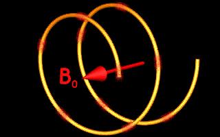
7 The magnet The magnet applies a static (homogeneous) magnetic field which align and precess the nuclei in the body. 7
8 The Shim Coils Shim coils create a homogeneous field by conforming the magnetic flux lines reducing in-homogeneities in the field. 8


9 Gradient Coils The gradient coils apply a variant of magnetic field strengths over the patient for spatial localization. 9

10 RF Coil or Antennae Radio frequencies are applied, the atoms absorb it and net magnetization changes. 10

11 Electronic Support System Processes the instructions of the Host Computer to the Pulse Sequence Controller 11
12 PULSE SEQUENCE CONTROLLER The pulse sequence controller is responsible for the timing and performance of each system component. The pulse sequence controller dictates when and how much gradient power is needed to vary the magnetic field and spatially encode the MR signal. 12
13 PULSE SEQUENCE CONTROLLER The pulse sequence controller also dictates when the RF energy must be transmitted and for how long. The signal power amplifier must be converted into an analog continuous waveform. The conversion is performed by the digital- to- analog converter (DAC). 13
14 DIGITAL-TO-ANALOG CONVERTER DAC The digital-to-analog converter is responsible for converting the digital instructions from the pulse sequence controller into a continuous analog wave form that is then passed through the RF power amplifier. 14
15 ARRAY PROCESSOR / The array processor is used to reconstruct images from raw data. It is in the array processor that the Fourier transform is applied. DISPLAY 15


16 The strength of a magnetic field is measured in units of induction, either Tesla or Gauss. 1 Tesla =10,000 Gauss = 10 kilogauss 16

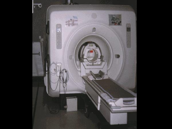
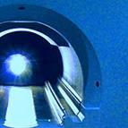
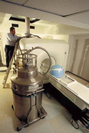
17 OVERVIEW of the MRI SYSTEM A magnet used for MRI must provide a high degree of magnetic field homogeneity over a large volume of a minimum of 36 centimeters. Magnet Bore 17

18 PERMANENT MAGNET Permanent magnets can be constructed from magnetized ceramic bricks. 18


19 The bricks are assembled such that their magnetic fields all face in the same direction above and below. Once assembled, their magnetic fields add together to make a strong opposing magnetic field between them. 19

20 PERMANENT MAGNET Magnetic fields can also be generated from a magnetized iron frame which acts to support the weight of the magnet as well as focus and constrain the field. These configurations establish a vertical magnetic field design. 20
21 Permanent Magnet Costs less to operate Allow larger bore size Accommodate larger patients Less chemical shift Smaller space requirements Heavy Field to about 0.3 tesla Cannot be turned off Require air-conditioning at a constant temperature to keep stable Require longer scan times 21

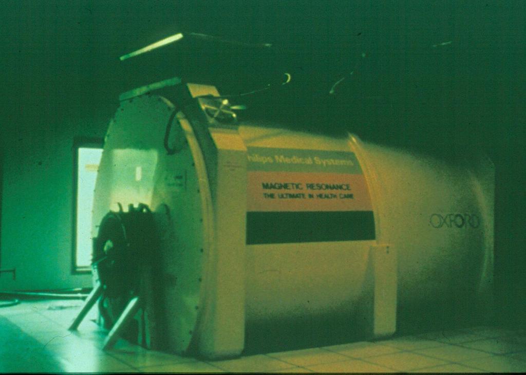
22 ELECTROMAGNET Electromagnets are made from coils of wire through which an electric current is passed. 22
23 ELECTRO or RESISTIVE MAGNET 23
24 24
25 wire FIELD By passing an electrical current through a coil made from looped niobium titanium wire, a magnetic field through the center of the coil is generated. Both resistive and superconducting magnets share this basic principle. 25

26 A basic law of magnetism states that if a charged particle is moved a distance along a path, a magnetic field will be generated perpendicular to the direction of the particle s motion. The direction of the magnetic field, when current flows through a coil of wire, is determined by the direction of the current. 26

27 To create strong electromagnetic fields, large amounts of currents must be used. The resistance built up in the wire will produce heat reducing the efficiency of the current and the reduction of the magnetic field through heat loss. 27
28 RESISTIVE MAGNET Can be quickly turned off Low- to mid- magnetic field Field strengths up to.38t Can be vertical or horizontal fields High power consumption Water cooling is required 28
29 SUPERCONDUCTIVE MAGNET 29

30 The entire system must be super cooled using liquid helium. By reducing the temperature down to near absolute zero, there is virtually no resistance in the wires. Stronger magnetic fields can be obtained with a superconducting magnet. 30

31 SUPERCONDUCTING MAGNETS Superconducting magnets are electromagnets super-cooled to near absolute zero. The coil of wire is made of Niobium Titanium. 31


32 CRYOGENS 32
33 SUPERCONDUCTIVE MAGNETS Large service requirements Cryogen maintenance requirements Large magnetic fringe field Magnetic field can be turned off Low power consumption High magnetic fields Stable magnetic field with homogeneity 33
34 Quench Unexpected loss of superconductivity in a superconducting magnet that causes heating and very rapid vaporization of the cryogens such as liquid helium. This can cause damage to the magnet and can force the atmosphere out of the scanner room potentially causing anoxic conditions. 34
35 Magnetic Shielding Magnetic shielding constricts the magnetic field flux lines to the magnetic room. With shielding the fringe field drops off to approximately the 5 Gauss limit line when outside of the scan room. 35
36 Magnetic Shielding Magnetic fringe fields must be minimized for patient safety and can be compensated for by the use of magnetic shielding. Passive-shielding Active-shielding Self-shielding 36
37 Shielding Design Passive-shielding uses steel in the walls of the scan room. Active-shielding uses solenoid magnets outside the cryogen bath that restrict the magnetic field lines to an acceptable location. Self-shielding uses steel in the magnet housing. 37
38 RF Shielding RF shielding assures that radio frequencies in the outside environment do not penetrate the MR scan room. Copper and stainless steel are used to create a Faraday cage inside the scan room to assure that no stray radio frequencies get in or out of the scan room. 38
39 The Shims Shimming is the process by which magnetic field inhomogeneities are greatly reduced. Shimming can be accomplished in two ways: passively and actively. 39

40 PASSIVE SHIM Passive shimming uses iron plates arranged at specific locations on the surface of the cylinder. 40

41 ACTIVE SHIM Coils of various geometry are selectively energized in order to produce local changes in the magnetic field where necessary. 41
42 GRADIENT COILS 42

43 GRADIENT COILS The gradient coils are thick bands of conductive material wrapped around a cylinder that fits inside the shim cylinder. There are three sets of coil pairs wrapped onto the cylinder s surface. There are also three gradient power amplifiers that drive electrical current through the gradient coils. 43

44 Magnet Cross-Section Patient Y gradient coil Z gradient coil Transceiver X gradient coil Main coil 44
 from one point in space to")
45 Gradient magnetic fields are used to spatially vary the magnetic field (amplitude/slope) from one point in space to another. 45
46 46
47 Gradient Polarity refers to whether the gradient magnetic field is creating a field greater than or less than the B0 field (at isocenter). Gradient fields are measured in millitesla per meter (mt/m). The speed at which a gradient produces it maximum field is its rise time (µsec). Slew rate is the acceleration of the gradient field to it maximum over time (T/m/sec). 47
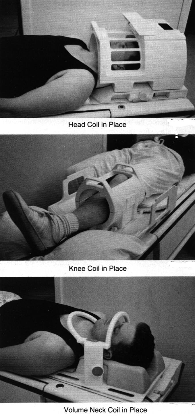
48 RF or IMAGING COILS The patient is placed in a RF coil. In its simplest form the RF coil is a loop of wire which acts as an antenna. 48
49 IMAGING COILS The closer a coil is to the area to be excited, the less RF energy needed to create transverse magnetization. The closer the receiver coil to the excited volume, the more signal detected. Therefore, surface coils improve the signal-tonoise ratio(snr). 49
50 COIL FUNCTION Two types of RF coils: transmitter coils and receiver coils. A single RF coil used for both transmitting the RF energy and receiving it. One coil as a transmitter and a second coil as a receiver. The transmitter coil must be large enough and positioned and shaped in such a way as to distribute the RF energy uniformly. When two different coils are used the coils must be decoupled or electrically isolated from one another so that energy is applied to only one coil at a time. 50

51 RECEIVER COILS 51
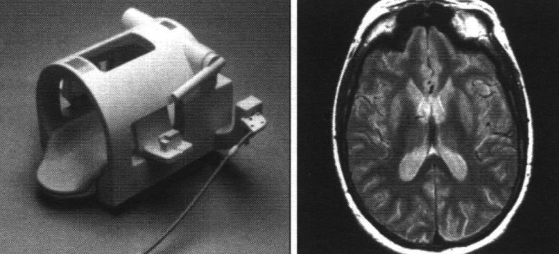
52 Volumetric Coils A volume coil both transmits RF and receives MR signal and is often called a transceiver. Even though volume coils are responsible for uniform excitation over a large area, because of their large size produce images with a lower SNR than other types of coils. The signal quality produced by volume coils has been significantly increased by doubling the coil sets within the imaging coil creating quadrature excitation and detection. This enables the signal to be transmitted and received by two pairs of coils. 52
53 Helmholtz Coil A Helmholtz configuration can be described as two coils working in tandem. The Helmholtz pair differs from the quadrature coil in that it is actually two linear coils. The purpose is to improve the signal through a volume of tissue. Only useful in horizontal magnetic fields designs. 53
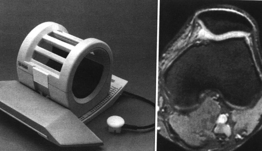
54 Solenoid Coils Solenoid coils are used with vertical field magnet designs. Most are separate transmit and receive coil configurations. Cannot be used with horizontal magnetic fields. 54
55 Quadrature / Multi-channel Coils Use two or more sets of coils sensitive to signal from only one polarization. Increased signal-to-noise, compared to linear coils. Increase speed of reception. Multi-channel coils can be transmit and/or receive coils. 55
56 Phased Array Several small coils in a coil holder is an array coil. Can switch between using one coil by itself or by using multiple coils together for larger coverage. In this way, the signal-to-noise ratios of a small coil can be combined to image a large area of interest. 56

57 57
58 Prescan These tasks must be done before scanning can be done: Shim magnetic field Tunes coil Set center frequency at isocenter Adjust transmit attenuation (RF Power Level) Adjust receiver attenuation (Receiver Gain) Failure to properly tune and match the coil may result in noisy images with poor contrast. 58
Weber State University Radiologic Technology 4603
 Weber State University Radiologic Technology 4603 MRI Physics and Instrumentation Instructor: Rex T. Christensen MHA R.T. (R) (MR) (CT) (ARRT) CIIP Contact Info: E-mail: rexchristensen@weber.edu Phone:
Background (~EE369B)
") Background (~EE369B) Magnetic Resonance Imaging D. Nishimura Overview of NMR Hardware Image formation and k-space Excitation k-space Signals and contrast Signal-to-Noise Ratio (SNR) Pulse Sequences 13
Background (~EE369B) Magnetic Resonance Imaging D. Nishimura Overview of NMR Hardware Image formation and k-space Excitation k-space Signals and contrast Signal-to-Noise Ratio (SNR) Pulse Sequences 13
M R I Physics Course. Jerry Allison Ph.D., Chris Wright B.S., Tom Lavin B.S., Nathan Yanasak Ph.D. Department of Radiology Medical College of Georgia
 M R I Physics Course Jerry Allison Ph.D., Chris Wright B.S., Tom Lavin B.S., Nathan Yanasak Ph.D. Department of Radiology Medical College of Georgia M R I Physics Course Magnetic Resonance Imaging Spatial
2 Hardware for Magnetic Resonance Imaging
 Hardware for Magnetic Resonance Imaging 13 2 Hardware for Magnetic Resonance Imaging Kenneth W. Fishbein, Joseph C. McGowan, and Richard G. Spencer CONTENTS 2.1 Introduction 13 2.2 Magnets 13 2.2.1 Permanent
Magnetic Resonance Imaging Principles, Methods, and Techniques
 Magnetic Resonance Imaging Principles, Methods, and Techniques Perry Sprawls Jr., Emory University Publisher: Medical Physics Publishing Corporation Publication Place: Madison, Wisconsin Publication Date:
Magnetic Resonance Imaging
 Magnetic Resonance Imaging Principles, Methods, and Techniques Perry Sprawls, Ph.D., FACR, FAAPM, FIOMP Distinguished Emeritus Professor Department of Radiology Emory University Atlanta, Georgia Medical
In an unmagnetized piece of iron, the atoms are arranged in domains. In each domain the atoms are aligned, but the domains themselves are random.
 4/7 Properties of the Magnetic Force 1. Perpendicular to the field and velocity. 2. If the velocity and field are parallel, the force is zero. 3. Roughly (field and vel perp), the force is the product
SPECIFICATION FOR A 7.0 TESLA/400MM ROOM TEMPERATURE BORE MAGNET SYSTEM
 SPECIFICATION FOR A 7.0 TESLA/400MM ROOM TEMPERATURE BORE MAGNET SYSTEM Prepared by:- Magnex Scientific Limited The Magnet Technology Centre 6 Mead Road Oxford Industrial Park Yarnton, Oxford OX5 1QU,
Magnetic Resonance Imaging and Radio Frequency. Part 1. Produced on behalf of Mid Sussex Amateur Radio Society by M5BTB
 Magnetic Resonance Imaging and Radio Frequency Part 1 Produced on behalf of Mid Sussex Amateur Radio Society by M5BTB Why Now? During 2011 my physical health was deteriorating, and a brain tumour was diagnosed
MRI Systems and Coil Technology
 MRI for Technologists MRI Systems and Coil Technology PROGRAM INFORMATION MRI for Technologists is a training program designed to meet the needs of radiologic technologists entering or working in the field
(N)MR Imaging. Lab Course Script. FMP PhD Autumn School. Location: C81, MRI Lab B0.03 (basement) Instructor: Leif Schröder. Date: November 3rd, 2010
MR Imaging. Lab Course Script. FMP PhD Autumn School. Location: C81, MRI Lab B0.03 (basement) Instructor: Leif Schröder. Date: November 3rd, 2010") (N)MR Imaging Lab Course Script FMP PhD Autumn School Location: C81, MRI Lab B0.03 (basement) Instructor: Leif Schröder Date: November 3rd, 2010 1 Purpose: Understanding the basic principles of MR imaging
(N)MR Imaging Lab Course Script FMP PhD Autumn School Location: C81, MRI Lab B0.03 (basement) Instructor: Leif Schröder Date: November 3rd, 2010 1 Purpose: Understanding the basic principles of MR imaging
MAGNETIC RESONANCE IMAGING
 CSEE 4620 Homework 3 Fall 2018 MAGNETIC RESONANCE IMAGING 1. THE PRIMARY MAGNET Magnetic resonance imaging requires a very strong static magnetic field to align the nuclei. Modern MRI scanners require
SPECIFICATIONS FOR A 4.7 TESLA/310MM BORE ACTIVELY SHIELDED MAGNET SYSTEM
 SPECIFICATIONS FOR A 4.7 TESLA/310MM BORE ACTIVELY SHIELDED MAGNET SYSTEM Prepared by:- Magnex Scientific Limited The Magnet Technology Centre 6 Mead Road Oxford Industrial Park Yarnton, Oxford OX5 1QU,
Hardware. MRI System. MRI system Multicoil Microstrip. Part1
 Hardware MRI system Multicoil Microstrip MRI System Part1 1 The MRI system is made up of a variety of subsystems. the Operator Workspace Gradient Driver subsystem The Physiological Acquisition Controller
Potential Risks of MRI in Device Patients
 Outline Potential Risks of MRI in Device Patients Redha Boubertakh r.boubertakh@qmul.ac.uk MRI and cardiac implantable electronic devices (CIED) Components of an MRI scanner MRI implant and device safety
The Pulsed Resistive Low-Field MR Scanner
 39 Chapter 3 The Pulsed Resistive Low-Field MR Scanner 3.1 Background In the remaining part of this work we are going to describe hyperpolarized gas relaxation, diffusion and MR imaging experiments. These
SPECIFICATIONS FOR AN MRBR 7.0 TESLA / 210MM ACTIVELY SHIELDED MAGNET SYSTEM
 SPECIFICATIONS FOR AN MRBR 7.0 TESLA / 210MM ACTIVELY SHIELDED MAGNET SYSTEM Prepared by:- Magnex Scientific Limited The Magnet Technology Centre 6 Mead Road Oxford Industrial Park Yarnton, Oxford OX5
Magnetic Resonance Imaging (MRI)
") C. A. Bouman: Digital Image Processing - February 15, 2 1 Magnetic Resonance Imaging (MRI) Can be very high resolution No radiation exposure Very flexible and programable Tends to be expensive, noisy,
C. A. Bouman: Digital Image Processing - February 15, 2 1 Magnetic Resonance Imaging (MRI) Can be very high resolution No radiation exposure Very flexible and programable Tends to be expensive, noisy,
SQUID - Superconducting QUantum Interference Device. Introduction History Operation Applications
 SQUID - Superconducting QUantum Interference Device Introduction History Operation Applications Introduction Very sensitive magnetometer Superconducting quantum interference device based on quantum effects
PRELIMINARY SPECIFICATIONS MRBR 7.0 TESLA / 210MM ACTIVELY SHIELDED CRYO-COOLED MAGNET SYSTEM
 PRELIMINARY SPECIFICATIONS MRBR 7.0 TESLA / 210MM ACTIVELY SHIELDED CRYO-COOLED MAGNET SYSTEM Prepared by:- Magnex Scientific Limited The Magnet Technology Centre 6 Mead Road Oxford Industrial Park Yarnton,
2015 Spin echoes and projection imaging
 1. Spin Echoes 1.1 Find f0, transmit amplitudes, and shim settings In order to acquire spin echoes, we first need to find the appropriate scanner settings using the FID GUI. This was all done last week,
MRI MRI REGISTRY REVIEW PHYSICAL PRINCIPLES OF IMAGE FORMATION ARTIFACTS SUPERCONDUCTIVE MAGNET ANAIBI MOLINA(R) (RT) (MR) (CT) T2 DEPHASING
 (RT) (MR) (CT) T2 DEPHASING") MRI ANAIBI MOLINA(R) (RT) (MR) (CT) T2 DEPHASING SUPERCONDUCTIVE MAGNET FREE INDUCTION DECAY ARTIFACTS MRI REGISTRY REVIEW PHYSICAL PRINCIPLES OF IMAGE FORMATION Mri Registry Review Physical Principles
MRI ANAIBI MOLINA(R) (RT) (MR) (CT) T2 DEPHASING SUPERCONDUCTIVE MAGNET FREE INDUCTION DECAY ARTIFACTS MRI REGISTRY REVIEW PHYSICAL PRINCIPLES OF IMAGE FORMATION Mri Registry Review Physical Principles
Field Simulation Software to Improve Magnetic Resonance Imaging
 Field Simulation Software to Improve Magnetic Resonance Imaging a joint project with the NRI in South Korea CST Usergroup Meeting 2010 Darmstadt Institute for Biometry and Medicine Informatics J. Mallow,
MARP. MR Accreditation Program Quality Control Beyond Just the Scans and Measurements July 2005
 ACR MRI accreditation program MR Accreditation Program Quality Control Beyond Just the Scans and Measurements July 2005 Carl R. Keener, Ph.D., DABMP, DABR keener@marpinc.com MARP Medical & Radiation Physics,
HETERONUCLEAR IMAGING. Topics to be Discussed:
 HETERONUCLEAR IMAGING BioE-594 Advanced MRI By:- Rajitha Mullapudi 04/06/2006 Topics to be Discussed: What is heteronuclear imaging. Comparing the hardware of MRI and heteronuclear imaging. Clinical applications
Receive Arrays and Circuitry
 Receive Arrays and Circuitry Cecilia Possanzini, Ph.D. Philips Healthcare, The Netherlands Email: cecilia.possanzini@philips.com Introduction This session provides an overview of the design principles
2.3 PF System. WU Weiyue PF5 PF PF1
 2.3 PF System WU Weiyue 2.3.1 Introduction The poloidal field (PF) system consists of fourteen superconducting coils, including 6 pieces of central selenoid coils, 4 pieces of divertor coils and 4 pieces
Introduction to MR Hardware. RF Coils C M L C T. = g * B 0. Rotating magnetization produces alternating magnetic field
 Introduction to MR Hardware RF Coils Dominik v. Elverfeldt Sep 5 th 2012 Courtesy of Hans Weber, Freiburg C M R = 50 Transmission = B 0 Reception L C T R Oscillating with Lamor frequency. B 1 field perpendicular
High Field MRI: Technology, Applications, Safety, and Limitations
 High Field MRI: Technology, Applications, Safety, and Limitations R. Jason Stafford, Ph.D. The University of Texas M. D. Anderson Cancer Center, Houston, TX Introduction The amount of available signal
The Battle of Carbon Steel
 More info ab The Battle of Carbon Steel Advantages of Eddy Current Array over Magnetic Particle and Penetrant Testing for Inspecting the Surface of Carbon Steel Welds Terence Burke Product Application
TECHNICAL SPECIFICATIONS. FOR AN MRBR 7.0 TESLA / 160mm ACTIVELY SHIELDED ROOM TEMPERATURE BORE MAGNET SYSTEM
 TECHNICAL SPECIFICATIONS FOR AN MRBR 7.0 TESLA / 160mm ACTIVELY SHIELDED ROOM TEMPERATURE BORE MAGNET SYSTEM Prepared by:- Magnex Scientific Limited The Magnet Technology Centre 6 Mead Road Oxford Industrial
7 Equipments. Spectrometers
 7 Equipments Spectrometers There are three spectrometers located in the NMR laboratory: Varian UNITYplus 500 MHz (NMR500), Varian UNITYplus 500 MHz (Nightmare) and Varian INOVA 600 MHz. All spectrometers
MAGNETOSCOP Measurement of magnetic field strengths in the range 0.1 nanotesla to 1 millitesla
 MAGNETOSCOP Measurement of magnetic field strengths in the range 0.1 nanotesla to 1 millitesla Extremely high sensitivity of 0.1 nanotesla with field and gradient probe Measurement of material permeabilities
DEVELOPMENT OF A BETA 0.12, 88 MHZ, QUARTER WAVE RESONATOR AND ITS CRYOMODULE FOR THE SPIRAL2 PROJECT
 DEVELOPMENT OF A BETA 0.12, 88 MHZ, QUARTER WAVE RESONATOR AND ITS CRYOMODULE FOR THE SPIRAL2 PROJECT G. Olry, J-L. Biarrotte, S. Blivet, S. Bousson, C. Commeaux, C. Joly, T. Junquera, J. Lesrel, E. Roy,
Analysis of magnetic and electromagnetic field emissions produced by a MRI device
 Sept. 8-1, 21, Kosice, Slovakia Analysis of magnetic and electromagnetic field emissions produced by a MRI device D. Giordano, M. Borsero, G. Crotti, M. ucca INRIM Istituto Nazionale di Ricerca Metrologica,
A Study of Magnetic Shielding Performance of a Fermilab International Linear Collider Superconducting RF Cavity Cryomodule
 A Study of Magnetic Shielding Performance of a Fermilab International Linear Collider Superconducting RF Cavity Cryomodule Anthony C. Crawford Fermilab Technical Div. / SRF Development Dept. acc52@fnal.gov
Welcome at MR Achieva 3.0T TX. About the system. Index. 1.1 Introduction
 1 Welcome at MR Achieva 3.0T TX Welcome to the Introduction of and e-learning module for the Achieva 3 Tesla TX-system. This CBT is setup for those engineers who will soon receive a Achieva 3Tesla TX system.
RF STATUS OF SUPERCONDUCTING MODULE DEVELOPMENT SUITABLE FOR CW OPERATION: ELBE CRYOSTATS
 RF STATUS OF SUPERCONDUCTING MODULE DEVELOPMENT SUITABLE FOR CW OPERATION: ELBE CRYOSTATS J. Teichert, A. Büchner, H. Büttig, F. Gabriel, P. Michel, K. Möller, U. Lehnert, Ch. Schneider, J. Stephan, A.
Installation und Kommissionierung des Viewray MRIdian Linac Hamburg, 28. Mai 2018 Sebastian Klüter
 Installation und Kommissionierung des Viewray MRIdian Linac Hamburg, 28. Mai 2018 Sebastian Klüter MR-guided RT in Heidelberg Funded by the German Research Foundation (DFG) Heidelberg consortium received
MRI Systems and Coil Technology
 MRI for Technologists MRI Systems and Coil Technology PROGRAM INFORMATION MRI for Technologists is a training program designed to meet the needs of radiologic technologists entering or working in the field
Compact yet Sophisticated
 Compact yet Sophisticated Hitachi has brought Open MRI one step further in its evolution, to better assist medical professionals who work at the forefront of healthcare. AIRIS Light MSK offers radiologists
Combined micropet /MR System: Performance Assessment of the Full PET Ring with Split Gradients 4.8
 Combined micropet /MR System: Performance Assessment of the Full PET Ring with Split Gradients 4.8 UNIVERSITY OF CAMBRIDGE 1.2 Rob C. Hawkes 1, Tim D. Fryer 1, Alun J. Lucas 1,2, Stefan B. Siegel 3, Richard
Ultrasonic Cleaning: How to select the best option
 Ultrasonic Cleaning: How to select the best option Marais 36 Phone/Fax: +41- (0)-32-9314045 2400, Le Locle email: mpi@mpi-ultrasonics.com Switzerland http://www.mpi-ultrasonics.com mpi@bluewin.ch http://mastersonic.com
New developments in near-field acoustic holography
 Please leave this heading unchanged! New developments in near-field acoustic holography N.B. Roozen*, A.C. Geerlings, B.T. Verhaar, T. Vliegenthart. Philips Applied Technologies, High Tech Campus 7, 5656
Designing an MR compatible Time of Flight PET Detector Floris Jansen, PhD, Chief Engineer GE Healthcare
 GE Healthcare Designing an MR compatible Time of Flight PET Detector Floris Jansen, PhD, Chief Engineer GE Healthcare There is excitement across the industry regarding the clinical potential of a hybrid
RF and Electronic Design Perspective on Ultra-High Field MRI systems
 RF and Electronic Design Perspective on Ultra-High Field MRI systems A DISSERTATION SUBMITTED TO THE FACULTY OF THE GRADUATE SCHOOL OF THE UNIVERSITY OF MINNESOTA BY SUNG-MIN SOHN IN PARTIAL FULFILLMENT
Electromagnet Motor Generator
 Magnetism and Electromagnetic Induction Study Guide Chapter 36 & 37 Key Terms: Magnetic Pole Magnetic Field Magnetic Domain Electromagnet Motor Generator Electromagnetic Induction Faraday s Law Transformer
1.5T HIGH FIELD SMALL ANIMAL MRI
 1.5T HIGH FIELD SMALL ANIMAL MRI Designed Specifically for Veterinarians TECHNICAL GUIDE ADVANCING THE ART AND SCIENCE OF VETERINARY MRI The PetVet is the only high-field MRI system designed specifically
S600X SQUID M AGNETOMETER. S600X - For better magnetic measurements. The Better Choice. AC and DC measurements.
 S600X SQUID M AGNETOMETER S600X - For better magnetic measurements AC and DC measurements. lo -8 EMU sensitivity for total moment. Oscillator and extraction mode. MilliTesla field resolution and setting.
Ileana-Diana Nicolae ICMET CRAIOVA UNIVERSITY OF CRAIOVA MAIN BUILDING FACULTY OF ELECTROTECHNICS
 The Designing, Realization and Testing of a Network Filter used to Reduce Electromagnetic Disturbances and to Improve the EMI for Static Switching Equipment Petre-Marian Nicolae Ileana-Diana Nicolae George
Suppression of Powerline Noise with Isolation Transformers
 Published and presented at EMC EXPO87, May 19-21, 1987, San Diego, CA Abstract Suppression of Powerline Noise with Isolation Transformers Bruce C. Gabrielson and Mark J. Reimold Sachs/Freeman Associates,
Central Time-of-Flight Magnetic Shield Performance Studies
 Central Time-of-Flight Magnetic Shield Performance Studies D.S. Carman, Jefferson Laboratory G. Asryan, A. Alikhanyan National Science Laboratory A. Ni, Kyungpook National University ctof field.tex July
7 Telsa SQUID Magnetometer
 7 Telsa SQUID Magnetometer Cryogen Free / Liquid Helium Cooled www.cryogenic.co.uk Introduction S700X - For better magnetic measurements Cryogen free or Liquid Helium based system High homogeneity 7 Tesla
Design of ESS-Bilbao RFQ Linear Accelerator
 Design of ESS-Bilbao RFQ Linear Accelerator J.L. Muñoz 1*, D. de Cos 1, I. Madariaga 1 and I. Bustinduy 1 1 ESS-Bilbao *Corresponding author: Ugaldeguren III, Polígono A - 7 B, 48170 Zamudio SPAIN, jlmunoz@essbilbao.org
Spiral MRI on a 9.4T Vertical-bore Superconducting Magnet Using Unshielded and Self-shielded Gradient Coils
 Magn Reson Med Sci doi:10.2463/mrms.tn.2016-0049 Published Online: March 27, 2017 TECHNICAL NOTE Spiral MRI on a 9.4T Vertical-bore Superconducting Magnet Using Unshielded and Self-shielded Gradient Coils
Acoustic noise reduction of MRI systems by means of magnetic shielding
 Acoustic noise reduction of MRI systems by means of magnetic shielding D. Biloen, N.B. Roozen Philips Applied Technologies, P.O.Box 218/Bldg. SAQ 2121, 56MD Eindhoven, The Netherlands {david.biloen, n.b.roozen}@philips.com,
TITLE: Prostate Cancer Detection Using High-Spatial Resolution MRI at 7.0 Tesla: Correlation with Histopathologic Findings at Radical Prostatectomy
 Award Number: W81XWH-11-1-0253 TITLE: Prostate Cancer Detection Using High-Spatial Resolution MRI at 7.0 Tesla: Correlation with Histopathologic Findings at Radical Prostatectomy PRINCIPAL INVESTIGATOR:
Chapter 21. Alternating Current Circuits and Electromagnetic Waves
 Chapter 21 Alternating Current Circuits and Electromagnetic Waves AC Circuit An AC circuit consists of a combination of circuit elements and an AC generator or source The output of an AC generator is sinusoidal
H 2 O and fat imaging
 H 2 O and fat imaging Xu Feng Outline Introduction benefit from the separation of water and fat imaging Chemical Shift definition of chemical shift origin of chemical shift equations of chemical shift
Medical Imaging. X-rays, CT/CAT scans, Ultrasound, Magnetic Resonance Imaging
 Medical Imaging X-rays, CT/CAT scans, Ultrasound, Magnetic Resonance Imaging From: Physics for the IB Diploma Coursebook 6th Edition by Tsokos, Hoeben and Headlee And Higher Level Physics 2 nd Edition
CHAPTER 5 Test B Lsn 5-6 to 5-8 TEST REVIEW
 IB PHYSICS Name: Period: Date: DEVIL PHYSICS BADDEST CLASS ON CAMPUS CHAPTER 5 Test B Lsn 5-6 to 5-8 TEST REVIEW 1. This question is about electric circuits. (a) (b) Define (i) (ii) electromotive force
A Complete Digital Magnetic Resonance Imaging (MRI) System at Low Magnetic Field (0.1 Tesla)
 System at Low Magnetic Field (0.1 Tesla)") IEEE Instrumentation and Measurement Technology Conference Anchorage, AK, USA, 21-23 May 2002 A Complete igital Magnetic Resonance Imaging (MRI) System at Low Magnetic Field (0.1 Tesla) Kosai RAOOF*, IEEE
IEEE Instrumentation and Measurement Technology Conference Anchorage, AK, USA, 21-23 May 2002 A Complete igital Magnetic Resonance Imaging (MRI) System at Low Magnetic Field (0.1 Tesla) Kosai RAOOF*, IEEE
Electro-optic components and system
 Electro-optic components and system Optical Isolators 700 Series Faraday Rotator and Accessories The unique feature of a Faraday rotator is its nonreciprocity, that is, the fact that the "handedness" of
Use of inductive heating for superconducting magnet protection*
 PSFC/JA-11-26 Use of inductive heating for superconducting magnet protection* L. Bromberg, J. V. Minervini, J.H. Schultz, T. Antaya and L. Myatt** MIT Plasma Science and Fusion Center November 4, 2011
Review of Progress in Quantitative Nondestructive Evaluation, Vol. 14 Edited by D.O. Thompson and D.E. Chimenti, Plenum Press, New Yorlc,l99S 1749
 MAGNETIC RESONANCE IMAGING AND SPECI'ROSCOPY USING SQUID DETECTION S. Kumar, W.F. Avrin, and B.D. Thorson Quantum Magnetics, Inc. 11578 Sorrento Valley Road San Diego, CA 92121 INTRODUCTION Magnetic Resonance
ABB flowmeter technology FSM4000 AC-excited magmeter
 White paper ABB flowmeter technology FSM4000 AC-excited magmeter Innovative AC-excited magmeter benefits pulp and paper operations by Greg Livelli, ABB Measurement Products Design innovations in AC-excited
A Conceptual Tour of Pulsed NMR*
 A Conceptual Tour of Pulsed NMR* Many nuclei, but not all, possess both a magnetic moment, µ, and an angular momentum, L. Such particles are said to have spin. When the angular momentum and magnetic moment
Chapter 2. Introduction to Functional MRI Hardware. Luis Hernandez-Garcia, Scott Peltier, and William Grissom. Abstract.
 Chapter 2 Introduction to Functional MRI Hardware Luis Hernandez-Garcia, Scott Peltier, and William Grissom Abstract The chapter gives an overview of peripheral devices commonly used in fmri experiments,
EE469B: Assignment 2 Solutions
 EE469B Fall 26-7 RF Pulse Design for MRI EE469B: Assignment 2 s Due Thursday Oct 3 Introduction This assignment concerns the design of small-tip-angle 2D excitation pulses based on spiral k-space trajectories.
Portable MRI Scanner by
 Portable MRI Scanner by ENSC 305/440 Simon Fraser University Team J: Anterpal Singh Sandhu Barry Yim Evangeline Yee Gagandeep Kaur Robin Wisniewski Date: 22 December 2015 Team Profile Evangeline Yee, CEO
Micro-manipulated Cryogenic & Vacuum Probe Systems
 Janis micro-manipulated probe stations are designed for non-destructive electrical testing using DC, RF, and fiber-optic probes. They are useful in a variety of fields including semiconductors, MEMS, superconductivity,
Lesson 06: Pulse-echo Imaging and Display Modes. These lessons contain 26 slides plus 15 multiple-choice questions.
 Lesson 06: Pulse-echo Imaging and Display Modes These lessons contain 26 slides plus 15 multiple-choice questions. These lesson were derived from pages 26 through 32 in the textbook: ULTRASOUND IMAGING
The promise of high-field MRI. High Field MRI Technology, Applications, Safety, and Limitations. High-field Scanners
 High Field MRI Technology, Applications, Safety, and Limitations R. Jason Stafford, Ph.D. Department of Imaging Physics The University of Texas M. D. Anderson Cancer Center Houston, TX The promise of high-field
Sample Testing with the Quadrupole Resonator A way to obtain RF results over a wide parameter range
 Sample Testing with the Quadrupole Resonator A way to obtain RF results over a wide parameter range Motivation Power consumption in a superconducting cavity is proportional to its surface resistance R
RAD 229: MRI Signals and Sequences
 RAD 229: MRI Signals and Sequences Brian Hargreaves All notes are on the course website web.stanford.edu/class/rad229 Course Goals Develop Intuition Understand MRI signals Exposure to numerous MRI sequences
Packaging of Cryogenic Components
 Packaging of Cryogenic Components William J. Schneider Senior Mechanical Engineer Emeritus November 19-23 2007 1 Packaging of Cryogenic Components Day one Introduction and Overview 2 What is important?
Analysis of spatial dependence of acoustic noise transfer function in magnetic resonance imaging
 Analysis of spatial dependence of acoustic noise transfer function in magnetic resonance imaging Award: Magna Cum Laude Poster No.: C-1988 Congress: ECR 2014 Type: Scientific Exhibit Authors: T. Hamaguchi,
CTOF Magnetic Shield Test Plan with FROST Magnet
 CTOF Magnetic Shield Test Plan with FROST Magnet D.S. Carman, Jefferson Laboratory A. Ni, Kyungpook National University shield-test.tex May 21, 2015 Abstract This document outlines the test plan for the
MRI RF-Coils. Innovation with Integrity. Highest sensitivity for your preclinical MRI and MRS applications. Preclinical Imaging
 MRI RF-Coils Highest sensitivity for your preclinical MRI and MRS applications Innovation with Integrity Preclinical Imaging Molecular and Preclinical Imaging Preclinical magnetic resonance imaging of
INDUCTOR. Inductors are electronic components that oppose a change in current. Air Core Inductor Symbol
 BASIC ELECTRICAL INDUCTOR INTRODUCTION are used for their ability to lter high frequencies out of the audio in a sound system. As an introduction to the focus of this lesson will be to discuss the different
General Physics (PHY 2140)
") General Physics (PHY 2140) Lecture 11 Electricity and Magnetism AC circuits and EM waves Resonance in a Series RLC circuit Transformers Maxwell, Hertz and EM waves Electromagnetic Waves 6/18/2007 http://www.physics.wayne.edu/~alan/2140website/main.htm
General Physics (PHY 2140) Lecture 11 Electricity and Magnetism AC circuits and EM waves Resonance in a Series RLC circuit Transformers Maxwell, Hertz and EM waves Electromagnetic Waves 6/18/2007 http://www.physics.wayne.edu/~alan/2140website/main.htm
NMR Basics. Lecture 2
 NMR Basics Lecture 2 Continuous wave (CW) vs. FT NMR There are two ways of tuning a piano: - key by key and recording each sound (or frequency). - or, kind of brutal, is to hit with a sledgehammer and
Magnetron. Physical construction of a magnetron
 anode block interaction space cathode filament leads Magnetron The magnetron is a high-powered vacuum tube that works as self-excited microwave oscillator. Crossed electron and magnetic fields are used
Name: Lab Partner: Section: The purpose of this lab is to study induction. Faraday s law of induction and Lenz s law will be explored. B = B A (8.
 Chapter 8 Induction - Faraday s Law Name: Lab Partner: Section: 8.1 Purpose The purpose of this lab is to study induction. Faraday s law of induction and Lenz s law will be explored. 8.2 Introduction It
Superconducting RF Cavity Performance Degradation after Quenching in Static Magnetic Field
 Superconducting RF Cavity Performance Degradation after Quenching in Static Magnetic Field T. Khabiboulline, D. Sergatskov, I. Terechkine* Fermi National Accelerator Laboratory (FNAL) *MS-316, P.O. Box
Electronic Systems - B1 23/04/ /04/ SisElnB DDC. Chapter 2
 Politecnico di Torino - ICT school Goup B - goals ELECTRONIC SYSTEMS B INFORMATION PROCESSING B.1 Systems, sensors, and actuators» System block diagram» Analog and digital signals» Examples of sensors»
ELECTRONIC SYSTEMS. Introduction. B1 - Sensors and actuators. Introduction
 Politecnico di Torino - ICT school Goup B - goals ELECTRONIC SYSTEMS B INFORMATION PROCESSING B.1 Systems, sensors, and actuators» System block diagram» Analog and digital signals» Examples of sensors»
RECENT ADVANCEMENTS IN THE APPLICATION OF EMATS TO NDE
 RECENT ADVANCEMENTS IN THE APPLICATION OF EMATS TO NDE D. MacLauchlan, S. Clark, B. Cox, T. Doyle, B. Grimmett, J. Hancock, K. Hour, C. Rutherford BWXT Services, Non Destructive Evaluation and Inspection
ISMRM weekend educational course, MR Systems Engineering, Console Electronics
 ISMRM weekend educational course, MR Systems Engineering, Console Electronics. 2013-4-20 Declaration of Relevant Financial Interests or Relationships Speaker Name: Katsumi Kose, Ph.D. I have the following
Ambient Conditions. Operating Conditions. Pressure
 Temperature Relative Humidity -20 C +75 C 0% 100 RH to 65 C non condensing 86 106 bar 4.0MPa (DN10 DN80) 1.6MPa (DN100 DN150) 1.0MPa (DN200 DN1000) Remote version < 80 C (rubber coating) Compact version
3D-Printed Microstrip Resonators for 4.7T MRI. Saeed Javidmehr. A thesis submitted in partial fulfillment of the requirements for the degree of
 3D-Printed Microstrip Resonators for 4.7T MRI by Saeed Javidmehr A thesis submitted in partial fulfillment of the requirements for the degree of Master of Science in Electromagnetics and Microwaves Department
3. What is hysteresis loss? Also mention a method to minimize the loss. (N-11, N-12)
") DHANALAKSHMI COLLEGE OF ENGINEERING, CHENNAI DEPARTMENT OF ELECTRICAL AND ELECTRONICS ENGINEERING EE 6401 ELECTRICAL MACHINES I UNIT I : MAGNETIC CIRCUITS AND MAGNETIC MATERIALS Part A (2 Marks) 1. List
DHANALAKSHMI COLLEGE OF ENGINEERING, CHENNAI DEPARTMENT OF ELECTRICAL AND ELECTRONICS ENGINEERING EE 6401 ELECTRICAL MACHINES I UNIT I : MAGNETIC CIRCUITS AND MAGNETIC MATERIALS Part A (2 Marks) 1. List
MR in RTP. MR Data for Treatment Planning: Spatial Accuracy Issues, Protocol Optimization, and Applications (Preview of TG117 Report) Acknowledgements
 Acknowledgements") MR Data for Treatment Planning: Issues, Protocol Optimization, and s (Preview of TG117 Report) Debra H. Brinkmann Mayo Clinic, Rochester MN Acknowledgements TG-117 Use of MRI Data in Treatment Planning
MR Data for Treatment Planning: Issues, Protocol Optimization, and s (Preview of TG117 Report) Debra H. Brinkmann Mayo Clinic, Rochester MN Acknowledgements TG-117 Use of MRI Data in Treatment Planning
Field Instrument Cable. Electrical Noise
 Field Instrument Cable Electrical Noise 1 Electrical Noise Instrument Cables are Susceptible to 4 Types of Noise: Static Magnetic Cross-Talk Common Mode 2 Static Noise Static Noise is caused by an electric
Inductors & Resonance
 Inductors & Resonance The Inductor This figure shows a conductor carrying a current. A magnetic field is set up around the conductor as concentric circles. If a coil of wire has a current flowing through
MRI & NMR spectrometer
 AMOS MRI & NMR spectrometer The AMOS Spectrometer is a highly modular and flexible unit that provides the ability to customize synchronized configurations for preclinical and clinical MR applications.
Properties of Inductor and Applications
 LABORATORY Experiment 3 Properties of Inductor and Applications 1. Objectives To investigate the properties of inductor for different types of magnetic material To calculate the resonant frequency of a
Fundamentals of NMR MRI Workshop Dayananda Sagar Institutes 29 May 2014 K.V.RAMANATHAN NMR Research Centre Indian Institute of Science Bangalore
 Fundamentals of NMR MRI Workshop Dayananda Sagar Institutes 29 May 2014 K.V.RAMANATHAN NMR Research Centre Indian Institute of Science Bangalore NMR It is an Ubiquitous Technique Physics Chemistry Structural
Basic NC and CNC. Dr. J. Ramkumar Professor, Department of Mechanical Engineering Micro machining Lab, I.I.T. Kanpur
 Basic NC and CNC Dr. J. Ramkumar Professor, Department of Mechanical Engineering Micro machining Lab, I.I.T. Kanpur Micro machining Lab, I.I.T. Kanpur Outline 1. Introduction to CNC machine 2. Component
T/R Switches, Baluns, and Detuning Elements in MRI RF coils Xiaoyu Yang 1,2, Tsinghua Zheng 1,2 and Hiroyuki Fujita 1,2,3.
 T/R Switches, Baluns, and Detuning Elements in MRI RF coils Xiaoyu Yang 1,2, Tsinghua Zheng 1,2 and Hiroyuki Fujita 1,2,3 1 Department of Physics, Case Western Reserve University 2 Department of Radiology,