Lesson 06: Pulse-echo Imaging and Display Modes. These lessons contain 26 slides plus 15 multiple-choice questions.
|
|
|
- May Watts
- 5 years ago
- Views:
Transcription

1 Lesson 06: Pulse-echo Imaging and Display Modes These lessons contain 26 slides plus 15 multiple-choice questions. These lesson were derived from pages 26 through 32 in the textbook:
2 ULTRASOUND IMAGING AND INSTRUMENTATION

3 Pulse-echo Imaging Voltage Sound Rectification Amplification Compensation Demodulation Compression Rejection Scan conversion Preprocessing Postprocessing Magnification All pulse-echo ultrasound systems contain the same basic components. The major components and their functions are best understood by referring to a block diagram.

4 TRANSDUCER EXCITATION AND OUTPUT POWER TRANSMITTER TRANSMIT POWER OUTPUT ACOUSTIC POWER ENERGY OUTPUT coded excitation: a method used to energize transducers by transmitting a long broadband pulse containing coded waveforms in order to increase the signal-to-noise ratio without loss of resolution The BEAMFORMER section of a pulseecho system provides the excitation to the TRANSDUCER. The excitation voltage from the beam former can be varied in some ultrasound systems. Varying the transducer's excitation voltage affects the amount of acoustic energy leaving the transducer. Various excitation methods are in use today including coded excitation, which improves signal-to-noise ratio. The frequency of the sound is not affected.
, which is determined by the TIMING section.")

5 TIMING PRF >1000 Hz The rate of recurrence of the beamformer s excitation to the transducer is the pulse repetition frequency (PRF), which is determined by the TIMING section. The timing section also provides synchronization to the rest of the system so that the returning echoes will be processed and displayed according to their proper axial positions (along the path of propagation).
6 RECEIVER TGC GAIN MASTER GAIN digital: a signal occurring in discrete steps over time and in sequence; signals converted into multiple discrete numerical values OVERALL GAIN The RECEIVER is used to provide the initial processing of the radio frequency echo information. After rectification, which eliminates either the positive or negative half of the received analog signal, some ultrasound systems immediately convert the information into digital signals prior to further receiver processing. The receiver s sensitivity is a measure of the weakest echoes that it can detect.


7 TIME GAIN COMPENSATION amplification: the process of increasing smaller voltages to larger ones Time Gain Compensation (TGC), often called Depth Gain Compensation is a receiver function that is used to equalize differences in received echo amplitudes due to reflector depth. TGC provides gradually increasing amplification with depth. The TGC control is just one of the receiverassociated controls that affect the amplification of echoes. The Overall Gain control affects all echoes regardless of depth. The actual names of the various controls will vary with each manufacturer.

8 TIME GAIN COMPENSATION Many manufacturers incorporate a group of sliding potentiometers to control the amplification of received echoes. Each TGC potentiometer is programmed to affect echoes returning from a specific depth. The TGC Curve is a graphic display of the settings of the receiver controls. More prominent TGC slopes are required when using higher frequency transducers.

9 GAIN vs. OUTPUT Nearly identical images may be obtained by using a low transducer outputpower setting along with high receiver-gain settings or by using a high transducer output-power setting along with low receiver-gain settings. From a safety standpoint, it is better to use higher gain settings and a lower outputpower setting.

10 TGC INCORRECT SETTINGS

11 DYNAMIC RANGE DYNAMIC RANGE COMPRESSION LOG COMPRESSION COMPRESS Another RECEIVER function is Dynamic Range, which is the ability to display both strong and weak echoes. It is the spectrum of values between minimum and maximum echo signal amplitudes.


12 DYNAMIC RANGE Increased dynamic range; decreased compression; wider range of displayed gray levels Decreased dynamic range; increased compression; smaller range of displayed gray levels contrast resolution: the ability to distinguish between shades of gray 50 db 30 db A wider dynamic range, which is often expressed in db, increases the contrast resolution by ensuring a wider range of displayed gray levels. Compression is a related function that decreases the difference between small and large amplitude signals. Compression effectively reduces the dynamic range of the receiver and the contrast resolution of the image.

13 NOISE REDUCTION REJECT low-level echoes (noise) anechoic noise: signals conveying unwanted echoes anechoic: the property of being echo-free or without echoes BEFORE REJECT AFTER REJECT In some receivers, a REJECT control is used to establish a threshold to suppress noise or background information. These unwanted echoes, occasionally appearing in an area that is normally anechoic, are often caused by electrical interference.
14 NOISE REDUCTION Other methods commonly used to suppress noise and improve signal-to-noise ratio include: Frame averaging (persistence), which reduces image noise by averaging and overlapping sequential real-time frames to provide spatial smoothing of the image. Frequency compounding, which is a method of transmitting a single broadband pulse and then using different receive frequency sub-bands. It reduces speckle and electronic noise to improve axial and contrast resolutions. Spatial compounding, which is the process of steering ultrasound beams offaxis to provide multiple transmit angles, or lines of sight while combining them in real-time during a single cross-sectional scan. Tissue interfaces are encountered from numerous directions rather than from a single direction. This helps eliminate certain artifact patterns to provide a more realistic anatomic representation. Reducing the acoustic shadows enables the scanner to essentially see around obstructions.
15 HARMONICS harmonic: a wave whose frequency is a wholenumber multiple of that of another Harmonic echoes are non-linear, high frequency signals created when a contrast agent or tissue interacts with ultrasound energy during pulse-echo and Doppler studies. Some harmonics are native to specific types and characteristics of tissue and are often produced without the use of a contrast agent. These tissue harmonics are decreased when lower transmit power is used.
16 HARMONIC IMAGING frame rate: the number of complete real-time images per second Harmonic imaging is a procedure in which the receiver detects only echoes at the second harmonic, which is twice the fundamental (transmitted) frequency. Harmonic imaging, to be effective, requires the use of broadband transducers. Harmonic imaging, by reducing unwanted artifacts caused by interaction with the fundamental frequency sound waves, provides improved contrast resolution, and reduced visible noise. By reducing side lobes and slice thickness, it improves lateral resolution. However, the lower fundamental frequency produces a longer spatial pulse length resulting in somewhat degraded axial resolution. Pulse inversion harmonic imaging is a non-linear imaging method specifically made for enhanced detection of microbubble ultrasound contrast media. Pulse inversion harmonic imaging has half the frame rate as conventional imaging. Axial resolution is somewhat improved compared to fundamental harmonic imaging.
17 DISPLAY MODES In an ultrasound imaging system, there are two basic modes that are used for the display of echoes that return to the transducer. The A-mode, which was routinely used in the early days of ultrasound, provides an amplitude-modulated display. The escalation of the displayed spikes is a relative indication of the intensity, or strength, of returning echoes. Although some ultrasound systems have A-mode display capabilities, its current use is limited. A-mode, when used for ophthalmic ultrasound applications, is called A-scan.
18 DISPLAY MODES B-mode provides a brightness-modulated display in which there is a change in spot brightness for each echo that is received by the transducer. In a B-mode ultrasound imaging system, the returning echoes are eventually displayed on a television monitor as shades of gray, which are discrete brightness levels. Typically, the brighter gray shades represent echoes with greater intensity levels.
19 DISPLAY MODES M-mode (motion-mode), which is often called TM-mode for time motion, produces a graphic B-mode pattern that represents the motion of structures along a single dimension time display, penetrated by a single ultrasound beam.


20 M-mode B-SCAN (2-D) M-MODE To assure accuracy of transducer positioning, a single-line cursor representing the M-mode line-of-sight is positioned on a 2D image to guide the M-mode ultrasound beam. M-mode, which is commonly used during echocardiographic studies, is often provided as an option on general-purpose ultrasound systems.
21 M-mode Although cardiac structures in an M-mode display are less identifiable than in a two-dimensional image, the resolution of the M-mode display is far superior. This is due to the typically narrow dimensions of the single M-mode ultrasound beam. M-mode is often preferable for evaluating subtle changes or rapid movements of the heart, which are too fast for the eye to see during twodimensional echocardiography. The use of M-mode is also dictated when precise timing of cardiac events is required.

22 B-scan B-mode is most commonly used to produce B-scans, or B-mode slices, which are two-dimensional (2-D) cross-sectional displays of objects through scanning planes. Real-time B-scanners produce live cross-sectional images.

23 B-scan Real-time B-scanners produce live cross-sectional images.
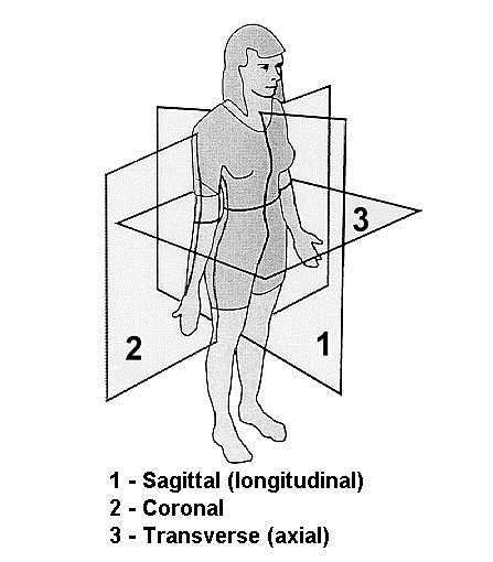
24 PATIENT-ORIENTED B-SCAN PLANES
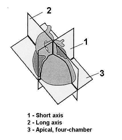
25 ORGAN-ORIENTED B-SCAN PLANES

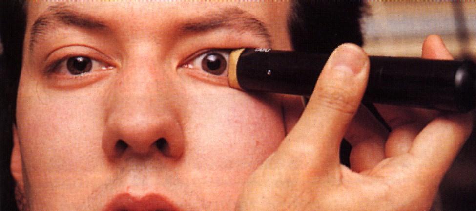
26 B-SCAN WITH A-SCAN OPHTHALMIC IMAGE
27 OBSTETRICAL IMAGES 2D 3D Scanners with 3-D capability collect volumetric data by manually (freehand) or automatically storing a series of 2-D slices in real-time and then performing the processing necessary to produce static (frozen) 3-D images. Live 3-D images are called 4-D.
28 Answers to the following FIFTEEN practice questions were derived from material in the textbook:
29 Question 1 Which of the following controls is part of the receiver in a pulse-echo ultrasound system? BRIGHTNESS XMTR PWR RES TGC POST PROCESSING Page 28
30 Question 1 Which of the following controls is part of the receiver in a pulse-echo ultrasound system? BRIGHTNESS XMTR PWR RES TGC POST PROCESSING Page 28
31 Question 2 The sensitivity of an ultrasound system may be determined by measuring the duty factor strongest echoes that are received bandwidth amplitude range of the received echoes weakest echoes that are received Page 27
32 Question 2 The sensitivity of an ultrasound system may be determined by measuring the duty factor strongest echoes that are received bandwidth amplitude range of the received echoes weakest echoes that are received Page 27
33 Question 3 If the OVERALL GAIN is decreased, only the brightness of the near echoes will decrease the energy to the patient is decreased the brightness of all echoes will decrease equally the frequency will decrease only the brightness of the far echoes will decrease Page 28
34 Question 3 If the OVERALL GAIN is decreased, only the brightness of the near echoes will decrease the energy to the patient is decreased the brightness of all echoes will decrease equally the frequency will decrease only the brightness of the far echoes will decrease Page 28
35 Question 4 If the ultrasound system displays only the echoes from strong reflectors and nothing else, the sonographer should increase the lateral resolution decrease the output power increase the overall gain decrease the slope of the TGC adjust the far gain Page 28
36 Question 4 If the ultrasound system displays only the echoes from strong reflectors and nothing else, the sonographer should increase the lateral resolution decrease the output power increase the overall gain decrease the slope of the TGC adjust the far gain Page 28
37 Question 5 The control that is used to suppress unwanted, low level echoes or background information is TGC POST PROCESSING DYNAMIC RANGE REJECT WRITE MAGNIFICATION Page 29
38 Question 5 The control that is used to suppress unwanted, low level echoes or background information is TGC POST PROCESSING DYNAMIC RANGE REJECT WRITE MAGNIFICATION Page 29
39 Question 6 Electrical interference could appear in an image as shadowing behind a poorly attenuating structure a decrease in far field penetration enhancement behind a highly reflective structure low-level echoes within a cyst a loss of axial resolution Page 29
40 Question 6 Electrical interference could appear in an image as shadowing behind a poorly attenuating structure a decrease in far field penetration enhancement behind a highly reflective structure low-level echoes within a cyst a loss of axial resolution Page 29
41 Question 7 The receiver dynamic range that provides the best opportunity for the display of a wide range of gray shades is 3 db 6 db 9 db 60 db 0 db Page 29
42 Question 7 The receiver dynamic range that provides the best opportunity for the display of a wide range of gray shades is 3 db 6 db 9 db 60 db 0 db Page 29
43 Question 8 Compression is used in the receiver of an ultrasound system to reduce the duty factor increase the difference between small and large amplitude signals reduce the range of signal amplitudes provide post processing reduce the sound energy entering the patient Page 29
44 Question 8 Compression is used in the receiver of an ultrasound system to reduce the duty factor increase the difference between small and large amplitude signals reduce the range of signal amplitudes provide post processing reduce the sound energy entering the patient Page 29
45 Question 9 The OUTPUT control on a pulse-echo ultrasound system controls the amount of amplification in the receiver varies the dynamic range in the receiver is used to equalize differences in received echo amplitudes due to differences in the depths of the reflectors varies the voltage that the beamformer supplies to the transducer does not have any affect on the amount of sound energy that enters a patient Page 26
46 Question 9 The OUTPUT control on a pulse-echo ultrasound system controls the amount of amplification in the receiver varies the dynamic range in the receiver is used to equalize differences in received echo amplitudes due to differences in the depths of the reflectors varies the voltage that the beamformer supplies to the transducer does not have any affect on the amount of sound energy that enters a patient Page 26
47 Question 10 The OUTPUT control in a pulse-echo system does NOT affect the excitation voltage that is applied to the transducer frequency of the sound that leaves the transducer energy that enters the patient amount of energy leaving a transducer overall gain that may be required Page 26
48 Question 10 The OUTPUT control in a pulse-echo system does NOT affect the excitation voltage that is applied to the transducer frequency of the sound that leaves the transducer energy that enters the patient amount of energy leaving a transducer overall gain that may be required Page 26
49 Question 11 From a safety standpoint, which one of the following methods is BEST? Low transmitter output and high receiver gain High near gain and low far gain High reject and high transmitter output High transmitter output and low receiver gain Low near gain and high far gain Page 28
50 Question 11 From a safety standpoint, which one of the following methods is BEST? Low transmitter output and high receiver gain High near gain and low far gain High reject and high transmitter output High transmitter output and low receiver gain Low near gain and high far gain Page 28
51 Question 12 The dynamic range of the receiver of an ultrasound system refers to the ability of the receiver to track a rapidly moving structure range of echo signal frequencies that can be processed without distortion speed with which the receiver recovers following the excitation pulse to the transducer depth range in tissue over which moving echoes can be received range of echo signal amplitudes that can be processed without distortion Page 29
52 Question 12 The dynamic range of the receiver of an ultrasound system refers to the ability of the receiver to track a rapidly moving structure range of echo signal frequencies that can be processed without distortion speed with which the receiver recovers following the excitation pulse to the transducer depth range in tissue over which moving echoes can be received range of echo signal amplitudes that can be processed without distortion Page 29
53 Question 13 Which of the following results in an increased acoustic exposure to the patient? application of reject increase in the swept gain slope rate increase in the television monitor brightness increase in the beamformer voltage to the transducer increase in the overall gain Page 26
54 Question 13 Which of the following results in an increased acoustic exposure to the patient? application of reject increase in the swept gain slope rate increase in the television monitor brightness increase in the beamformer voltage to the transducer increase in the overall gain Page 26
55 Question 14 Which of the following is NOT a brightness-modulated display, based on the amplitude of received echoes? B mode B scan A mode Real time gray scale M mode Page 31
56 Question 14 Which of the following is NOT a brightness-modulated display, based on the amplitude of received echoes? B mode B scan A mode Real time gray scale M mode Page 31
57 Question 15 Increasing the gain of a pulse-echo system results in higher A-mode echoes. This is due to increased amount of sound emitted by the transducer increased amount of sound reflected increased efficiency of transducer conversion of sound into electricity increased amplification in the receiver decreased amplification in the receiver Pages 28 and 31
58 Question 15 Increasing the gain of a pulse-echo system results in higher A-mode echoes. This is due to increased amount of sound emitted by the transducer increased amount of sound reflected increased efficiency of transducer conversion of sound into electricity increased amplification in the receiver decreased amplification in the receiver Pages 28 and 31
59 END OF LESSON 06
Lesson 06: Pulse-echo Imaging and Display Modes. This lesson contains 22 slides plus 15 multiple-choice questions.
 Lesson 06: Pulse-echo Imaging and Display Modes This lesson contains 22 slides plus 15 multiple-choice questions. Accompanying text for the slides in this lesson can be found on pages 26 through 32 in
Answer: TGC is needed to amplify echoes from deeper structures so that they appear as bright as similar structures located at more shallow depths.
 Q47. When performing a sonogram why the sonographer needs to use the TGC? TGC is needed to amplify echoes from deeper structures so that they appear as bright as similar structures located at more shallow
Artifacts. Artifacts. Causes. Imaging assumptions. Common terms used to describe US images. Common terms used to describe US images
 Artifacts Artifacts Chapter 20 What are they? Simply put they are an error in imaging These artifacts include reflections that are: not real incorrect shape, size or position incorrect brightness displayed
Optimisation of Image Acquisition Bordeaux 16th November J.S. McGhie W.B. Vletter R. Frowijn No disclosures
 Optimisation of Image Acquisition Bordeaux 16th November 2016 J.S. McGhie W.B. Vletter R. Frowijn No disclosures Image optimisation: The Echo machine It looks difficult to drive an echo machine!! Some
The Physics of Echo. The Physics of Echo. The Physics of Echo Is there pericardial calcification? 9/30/13
 Basic Ultrasound Physics Kirk Spencer MD Speaker has no disclosures to make Sound Audible range 20Khz Medical ultrasound Megahertz range Advantages of imaging with ultrasound Directed as a beam Tomographic
Physics of Ultrasound Ultrasound Imaging and Artifacts รศ.นพ.เดโช จ กราพาน ชก ล สาขาหท ยว ทยา, ภาคว ชาอาย รศาสตร คณะแพทยศาสตร ศ ร ราชพยาบาล
 Physics of Ultrasound Ultrasound Imaging and Artifacts รศ.นพ.เดโช จ กราพาน ชก ล สาขาหท ยว ทยา, ภาคว ชาอาย รศาสตร คณะแพทยศาสตร ศ ร ราชพยาบาล Diagnosis TTE TEE ICE 3D 4D Evaluation of Cardiac Anatomy Hemodynamic
Ultrasound Beamforming and Image Formation. Jeremy J. Dahl
 Ultrasound Beamforming and Image Formation Jeremy J. Dahl Overview Ultrasound Concepts Beamforming Image Formation Absorption and TGC Advanced Beamforming Techniques Synthetic Receive Aperture Parallel
Ultrasound & Artifacts
 ISSN 2005-7881 Journal of Neurosonology 3(Suppl. 2):1-17, 2011 Ultrasound & Artifacts Siryung Han The Catholic University of Korea Artifacts False image- echoes without anatomic correlate US image dose
Ultrasound Imaging Ultr Michael Dadd 2007
 Ultrasound Imaging Ultrasound Physics & Instrumentation - Recommended Reading 1. Diagnostic Ultrasound: Principles and Instruments (7th Ed) Frederick W Kremkau W B Saunders Company 2. Applied Physics &
Pass Ultrasound Physics Exam
 Pass Ultrasound Physics Exam Match the Answers By Mansoor Khan MBBS, RDMS, RDCS 1 Copyright 2014 Blue Cube Venture, LLC All rights reserved. The Pass Ultrasound Physics Exam Match the Answers is protected
Ultrasound physical principles in today s technology
 Education Ultrasound physical principles in today s technology Brian Starkoff M.App.Sc.(Med. Ultrasound), AMS Holland Park Brisbane Queensland Australia Correspondence to email starkoff@optusnet.com.au
Ultrasound Bioinstrumentation. Topic 2 (lecture 3) Beamforming
 Beamforming") Ultrasound Bioinstrumentation Topic 2 (lecture 3) Beamforming Angular Spectrum 2D Fourier transform of aperture Angular spectrum Propagation of Angular Spectrum Propagation as a Linear Spatial Filter Free
Ultrasound Bioinstrumentation Topic 2 (lecture 3) Beamforming Angular Spectrum 2D Fourier transform of aperture Angular spectrum Propagation of Angular Spectrum Propagation as a Linear Spatial Filter Free
Ultrasound Physics. History: Ultrasound 2/13/2019. Ultrasound
 Ultrasound Physics History: Ultrasound Ultrasound 1942: Dr. Karl Theodore Dussik transmission ultrasound investigation of the brain 1949-51: Holmes and Howry subject submerged in water tank to achieve
The physics of ultrasound. Dr Graeme Taylor Guy s & St Thomas NHS Trust
 The physics of ultrasound Dr Graeme Taylor Guy s & St Thomas NHS Trust Physics & Instrumentation Modern ultrasound equipment is continually evolving This talk will cover the basics What will be covered?
12/26/2017. Alberto Ardon M.D.
 Alberto Ardon M.D. 1 Preparatory Work Ultrasound Physics http://www.nysora.com/mobile/regionalanesthesia/foundations-of-us-guided-nerve-blockstechniques/index.1.html Basic Ultrasound Handling https://www.youtube.com/watch?v=q2otukhrruc
3. Ultrasound Imaging(2)
") 3. Ultrasound Imaging(2) Lecture 13, 14 Medical Imaging Systems Jae Gwan Kim, Ph.D. jaekim@gist.ac.kr, X 2220 Department of BioMedical Science and Engineering Gwangju Institute of Sciences and Technology
3. Ultrasound Imaging(2) Lecture 13, 14 Medical Imaging Systems Jae Gwan Kim, Ph.D. jaekim@gist.ac.kr, X 2220 Department of BioMedical Science and Engineering Gwangju Institute of Sciences and Technology
4 Working With Scan Modes
 4 Working With Scan Modes Scan Modes Overview All of the information in this chapter pertains to live imaging. Many of the controls and functions change when you freeze the scan. For information on using
MAKING TRANSIENT ANTENNA MEASUREMENTS
 MAKING TRANSIENT ANTENNA MEASUREMENTS Roger Dygert, Steven R. Nichols MI Technologies, 1125 Satellite Boulevard, Suite 100 Suwanee, GA 30024-4629 ABSTRACT In addition to steady state performance, antennas
Chapter 4. Pulse Echo Imaging. where: d = distance v = velocity t = time
 Chapter 4 Pulse Echo Imaging Ultrasound imaging systems are based on the principle of pulse echo imaging. These systems require the use of short pulses of ultrasound to create two-dimensional, sectional
ULTRASONIC IMAGING of COPPER MATERIAL USING HARMONIC COMPONENTS
 ULTRASONIC IMAGING of COPPER MATERIAL USING HARMONIC COMPONENTS T. Stepinski P. Wu Uppsala University Signals and Systems P.O. Box 528, SE- 75 2 Uppsala Sweden ULTRASONIC IMAGING of COPPER MATERIAL USING
Lesson 12: Doppler Principles. This lesson contains 50 slides plus 26 multiple-choice questions.
 Lesson 12: Doppler Principles This lesson contains 50 slides plus 26 multiple-choice questions. Accompanying text for the slides in this lesson can be found on pages 59 through 80 in the textbook: DOPPLER
Lesson 02: Sound Wave Production. This lesson contains 24 slides plus 11 multiple-choice questions.
 Lesson 02: Sound Wave Production This lesson contains 24 slides plus 11 multiple-choice questions. Accompanying text for the slides in this lesson can be found on pages 2 through 7 in the textbook: ULTRASOUND
Introduction. Parametric Imaging. The Ultrasound Research Interface: A New Tool for Biomedical Investigations
 The Ultrasound Research Interface: A New Tool for Biomedical Investigations Shelby Brunke, Laurent Pelissier, Kris Dickie, Jim Zagzebski, Tim Hall, Thaddeus Wilson Siemens Medical Systems, Issaquah WA
CHAPTER 1 INTRODUCTION
 CHAPTER 1 INTRODUCTION Spatial resolution in ultrasonic imaging is one of many parameters that impact image quality. Therefore, mechanisms to improve system spatial resolution could result in improved
An Overview Algorithm to Minimise Side Lobes for 2D Circular Phased Array
 An Overview Algorithm to Minimise Side Lobes for 2D Circular Phased Array S. Mondal London South Bank University; School of Engineering 103 Borough Road, London SE1 0AA More info about this article: http://www.ndt.net/?id=19093
Photomultiplier Tube
 Nuclear Medicine Uses a device known as a Gamma Camera. Also known as a Scintillation or Anger Camera. Detects the release of gamma rays from Radionuclide. The radionuclide can be injected, inhaled or
Image Optimization: The Sonographer s Responsibility. Prepared by Cathy Daniels, EdD, RTR, RDMS, RDCS, RVT
 Image Optimization: The Sonographer s Responsibility Prepared by Cathy Daniels, EdD, RTR, RDMS, RDCS, RVT Image Optimization: The Sonographer s Responsibility Cathy Daniels, EdD, RTR, RDMS, RDCS, RVT Disclosure
Performing ultrasound probe quality assurance assessments: A How-to Guide
 Performing ultrasound probe quality assurance assessments: A How-to Guide A comprehensive quality assurance program has the potential to directly contribute to better patient outcomes. Regular testing
Medical Imaging (EL582/BE620/GA4426)
") Medical Imaging (EL582/BE620/GA4426) Jonathan Mamou, PhD Riverside Research Lizzi Center for Biomedical Engineering New York, NY jmamou@riversideresearch.org On behalf of Prof. Daniel Turnbull Outline
Medical Imaging (EL582/BE620/GA4426) Jonathan Mamou, PhD Riverside Research Lizzi Center for Biomedical Engineering New York, NY jmamou@riversideresearch.org On behalf of Prof. Daniel Turnbull Outline
The quality of the transmission signal The characteristics of the transmission medium. Some type of transmission medium is required for transmission:
 Data Transmission The successful transmission of data depends upon two factors: The quality of the transmission signal The characteristics of the transmission medium Some type of transmission medium is
Lecture 6 SIGNAL PROCESSING. Radar Signal Processing Dr. Aamer Iqbal Bhatti. Dr. Aamer Iqbal Bhatti
 Lecture 6 SIGNAL PROCESSING Signal Reception Receiver Bandwidth Pulse Shape Power Relation Beam Width Pulse Repetition Frequency Antenna Gain Radar Cross Section of Target. Signal-to-noise ratio Receiver
Chapter-15. Communication systems -1 mark Questions
 Chapter-15 Communication systems -1 mark Questions 1) What are the three main units of a Communication System? 2) What is meant by Bandwidth of transmission? 3) What is a transducer? Give an example. 4)
Breast Ultrasound QA Phantom Recommended by Japan Association of Breast and Thyroid Sonology
 Breast Ultrasound QA Phantom Recommended by Japan Association of Breast and Thyroid Sonology Product supervision: Japan Association of Breast and Thyroid Sonology, Quality Assurance Committee Working Team.
SECTION I - CHAPTER 2 DIGITAL IMAGING PROCESSING CONCEPTS
 RADT 3463 - COMPUTERIZED IMAGING Section I: Chapter 2 RADT 3463 Computerized Imaging 1 SECTION I - CHAPTER 2 DIGITAL IMAGING PROCESSING CONCEPTS RADT 3463 COMPUTERIZED IMAGING Section I: Chapter 2 RADT
Using Frequency Diversity to Improve Measurement Speed Roger Dygert MI Technologies, 1125 Satellite Blvd., Suite 100 Suwanee, GA 30024
 Using Frequency Diversity to Improve Measurement Speed Roger Dygert MI Technologies, 1125 Satellite Blvd., Suite 1 Suwanee, GA 324 ABSTRACT Conventional antenna measurement systems use a multiplexer or
Principles of Ultrasound Imaging Image Optimization
 Principles of Ultrasound Imaging Image Optimization Robert A. Levine, MD, FACE, ECNU Thyroid Center of New Hampshire Geisel School of Medicine at Dartmouth College Disclosures: No relevant financial or
Lecture 3: Data Transmission
 Lecture 3: Data Transmission 1 st semester 1439-2017 1 By: Elham Sunbu OUTLINE Data Transmission DATA RATE LIMITS Transmission Impairments Examples DATA TRANSMISSION The successful transmission of data
Nuove tecnologie per ecografia ad ultrasuoni: da 2D a 4D
 DINFO Dipartimento di Ingegneria dell Informazione Department of Information Engineering Nuove tecnologie per ecografia ad ultrasuoni: da 2D a 4D Piero Tortoli Microelectronics Systems Design Lab 1 Introduction
Physics of ultrasound
 1 Physics of ultrasound Basic principles Nature of ultrasound Sound = longitudinal, mechanical wave particles move parallel to direction of travel Audible sound < 20 khz Ultrasound > 20 khz Sound cannot
DC-6. Diagnostic Ultrasound System
 DC-6 Diagnostic Ultrasound System DC-6 is a general purpose color Doppler ultrasound system aiming at most clinical areas both in exam and research with various transducers and multi software packages
Real Time Deconvolution of In-Vivo Ultrasound Images
 Paper presented at the IEEE International Ultrasonics Symposium, Prague, Czech Republic, 3: Real Time Deconvolution of In-Vivo Ultrasound Images Jørgen Arendt Jensen Center for Fast Ultrasound Imaging,
Some key functions implemented in the transmitter are modulation, filtering, encoding, and signal transmitting (to be elaborated)
") 1 An electrical communication system enclosed in the dashed box employs electrical signals to deliver user information voice, audio, video, data from source to destination(s). An input transducer may be
1 An electrical communication system enclosed in the dashed box employs electrical signals to deliver user information voice, audio, video, data from source to destination(s). An input transducer may be
Signal Characteristics
 Data Transmission The successful transmission of data depends upon two factors:» The quality of the transmission signal» The characteristics of the transmission medium Some type of transmission medium
Analog Circuits and Systems
 Analog Circuits and Systems Prof. K Radhakrishna Rao Lecture 21: Filters 1 Review Integrators as building blocks of filters Frequency compensation in negative feedback systems Opamp and LDO frequency compensation
The Middle East Distributor for AMBISEA Technology Corp. Electro-Medical Product Line
 The Middle East Distributor for AMBISEA Technology Corp. Electro-Medical Product Line AV-9100 Single Channel ECG 1 2 AV-9300 3-Channels ECG 3 4 5 AV-9000B Multi-Parameter Patient Monitor 6 7 8 AV-9000C
Data Communication. Chapter 3 Data Transmission
 Data Communication Chapter 3 Data Transmission ١ Terminology (1) Transmitter Receiver Medium Guided medium e.g. twisted pair, coaxial cable, optical fiber Unguided medium e.g. air, water, vacuum ٢ Terminology
Structure of Speech. Physical acoustics Time-domain representation Frequency domain representation Sound shaping
 Structure of Speech Physical acoustics Time-domain representation Frequency domain representation Sound shaping Speech acoustics Source-Filter Theory Speech Source characteristics Speech Filter characteristics
Introduction to Ultrasound Physics
 Introduction to Ultrasound Physics Vassilis Sboros Medical Physics and Cardiovascular Sciences University of Edinburgh Transverse waves Water remains in position Disturbance traverse producing more wave
Terminology (1) Chapter 3. Terminology (3) Terminology (2) Transmitter Receiver Medium. Data Transmission. Direct link. Point-to-point.
 Chapter 3. Terminology (3) Terminology (2) Transmitter Receiver Medium. Data Transmission. Direct link. Point-to-point.") Terminology (1) Chapter 3 Data Transmission Transmitter Receiver Medium Guided medium e.g. twisted pair, optical fiber Unguided medium e.g. air, water, vacuum Spring 2012 03-1 Spring 2012 03-2 Terminology
Terminology (1) Chapter 3 Data Transmission Transmitter Receiver Medium Guided medium e.g. twisted pair, optical fiber Unguided medium e.g. air, water, vacuum Spring 2012 03-1 Spring 2012 03-2 Terminology
Retrospective Transmit Beamformation. Whitepaper. ACUSON SC2000 Volume Imaging Ultrasound System. Answers for life.
 Whitepaper Retrospective Transmit Beamformation ACUSON SC2000 Volume Imaging Ultrasound System Chuck Bradley, Ph.D. Siemens Healthcare Sector Ultrasound Business Unit Mountain View, California USA Answers
High Dynamic Range Receiver Parameters
 High Dynamic Range Receiver Parameters The concept of a high-dynamic-range receiver implies more than an ability to detect, with low distortion, desired signals differing, in amplitude by as much as 90
MRI Summer Course Lab 2: Gradient Echo T1 & T2* Curves
 MRI Summer Course Lab 2: Gradient Echo T1 & T2* Curves Experiment 1 Goal: Examine the effect caused by changing flip angle on image contrast in a simple gradient echo sequence and derive T1-curves. Image
Doppler in Obstetrics: book by K Nicolaides, G Rizzo, K Hecher. Chapter on Doppler ultrasound: principles and practice by Colin Deane
 Doppler in Obstetrics: book by K Nicolaides, G Rizzo, K Hecher Chapter on Doppler ultrasound: principles and practice by Colin Deane INTRODUCTION Competent use of Doppler ultrasound techniques requires
Data Transmission. ITS323: Introduction to Data Communications. Sirindhorn International Institute of Technology Thammasat University ITS323
 ITS323: Introduction to Data Communications Sirindhorn International Institute of Technology Thammasat University Prepared by Steven Gordon on 23 May 2012 ITS323Y12S1L03, Steve/Courses/2012/s1/its323/lectures/transmission.tex,
Lecture Fundamentals of Data and signals
 IT-5301-3 Data Communications and Computer Networks Lecture 05-07 Fundamentals of Data and signals Lecture 05 - Roadmap Analog and Digital Data Analog Signals, Digital Signals Periodic and Aperiodic Signals
COMPUTER PHANTOMS FOR SIMULATING ULTRASOUND B-MODE AND CFM IMAGES
 Paper presented at the 23rd Acoustical Imaging Symposium, Boston, Massachusetts, USA, April 13-16, 1997: COMPUTER PHANTOMS FOR SIMULATING ULTRASOUND B-MODE AND CFM IMAGES Jørgen Arendt Jensen and Peter
AN EMAT ARRAY FOR THE RAPID INSPECTION OF LARGE STRUCTURES USING GUIDED WAVES. Paul Wilcox 1, Mike Lowe 2
 AN EMAT ARRAY FOR THE RAPID INSPECTION OF LARGE STRUCTURES USING GUIDED WAVES Paul Wilcox 1, Mike Lowe 2 least as important as the issue of modal selectivity. For example, a defect free rectangular plate
Data Communications & Computer Networks
 Data Communications & Computer Networks Chapter 3 Data Transmission Fall 2008 Agenda Terminology and basic concepts Analog and Digital Data Transmission Transmission impairments Channel capacity Home Exercises
Understanding How Frequency, Beam Patterns of Transducers, and Reflection Characteristics of Targets Affect the Performance of Ultrasonic Sensors
 Characteristics of Targets Affect the Performance of Ultrasonic Sensors By Donald P. Massa, President and CTO of Massa Products Corporation Overview of How an Ultrasonic Sensor Functions Ultrasonic sensors
Key Physics and Doppler Principles
 Key Physics and Doppler Principles Robert A. Levine, MD, FACE, ECNU Thyroid Center of New Hampshire Geisel School of Medicine at Dartmouth College AACE/ACE Advanced Neck Ultrasound Training Course Disclosures:
Contents. Telecom Service Chae Y. Lee. Data Signal Transmission Transmission Impairments Channel Capacity
 Data Transmission Contents Data Signal Transmission Transmission Impairments Channel Capacity 2 Data/Signal/Transmission Data: entities that convey meaning or information Signal: electric or electromagnetic
Terminology (1) Chapter 3. Terminology (3) Terminology (2) Transmitter Receiver Medium. Data Transmission. Simplex. Direct link.
 Chapter 3. Terminology (3) Terminology (2) Transmitter Receiver Medium. Data Transmission. Simplex. Direct link.") Chapter 3 Data Transmission Terminology (1) Transmitter Receiver Medium Guided medium e.g. twisted pair, optical fiber Unguided medium e.g. air, water, vacuum Corneliu Zaharia 2 Corneliu Zaharia Terminology
Chapter 3 Data Transmission Terminology (1) Transmitter Receiver Medium Guided medium e.g. twisted pair, optical fiber Unguided medium e.g. air, water, vacuum Corneliu Zaharia 2 Corneliu Zaharia Terminology
Antenna Measurements using Modulated Signals
 Antenna Measurements using Modulated Signals Roger Dygert MI Technologies, 1125 Satellite Boulevard, Suite 100 Suwanee, GA 30024-4629 Abstract Antenna test engineers are faced with testing increasingly
Data and Computer Communications Chapter 3 Data Transmission
 Data and Computer Communications Chapter 3 Data Transmission Eighth Edition by William Stallings Transmission Terminology data transmission occurs between a transmitter & receiver via some medium guided
White Rose Research Online URL for this paper: Version: Accepted Version
 This is a repository copy of Enhancement of contrast and resolution of B-mode plane wave imaging (PWI) with non-linear filtered delay multiply and sum () beamforming. White Rose Research Online URL for
Quick Reference Guide
 siemens.com/nx3 Quick Reference Guide ACUSON NX3 Series Contents 2 System Overview 3 Getting Started 8 2D Mode and M-mode 12 Color and Spectral Doppler 24 Measurements and Calculations 38 Text, Arrows
Architecture of Quality Imaging Mary K. Henne, MS, CNMT, RDMS, RVT Ultrasound Education Specialist GE Healthcare
 Architecture of Quality Imaging Mary K. Henne, MS, CNMT, RDMS, RVT Ultrasound Education Specialist GE Healthcare 2 DOC1292532 Architecture of Quality Imaging Agile Acoustic Architecture E-Series and XDclear
CHAPTER -15. Communication Systems
 CHAPTER -15 Communication Systems COMMUNICATION Communication is the act of transmission and reception of information. COMMUNICATION SYSTEM: A system comprises of transmitter, communication channel and
Overview. Lecture 3. Terminology. Terminology. Background. Background. Transmission basics. Transmission basics. Two signal types
 Lecture 3 Transmission basics Chapter 3, pages 75-96 Dave Novak School of Business University of Vermont Overview Transmission basics Terminology Signal Channel Electromagnetic spectrum Two signal types
Chapter 2 Channel Equalization
 Chapter 2 Channel Equalization 2.1 Introduction In wireless communication systems signal experiences distortion due to fading [17]. As signal propagates, it follows multiple paths between transmitter and
Multi-Element Synthetic Transmit Aperture Method in Medical Ultrasound Imaging Ihor Trots, Yuriy Tasinkevych, Andrzej Nowicki and Marcin Lewandowski
 Multi-Element Synthetic Transmit Aperture Method in Medical Ultrasound Imaging Ihor Trots, Yuriy Tasinkevych, Andrzej Nowicki and Marcin Lewandowski Abstract The paper presents the multi-element synthetic
Basic Radar Definitions Introduction p. 1 Basic relations p. 1 The radar equation p. 4 Transmitter power p. 9 Other forms of radar equation p.
 Basic Radar Definitions Basic relations p. 1 The radar equation p. 4 Transmitter power p. 9 Other forms of radar equation p. 11 Decibel representation of the radar equation p. 13 Radar frequencies p. 15
Keywords: Ultrasonic Testing (UT), Air-coupled, Contact-free, Bond, Weld, Composites
, Air-coupled, Contact-free, Bond, Weld, Composites") Single-Sided Contact-Free Ultrasonic Testing A New Air-Coupled Inspection Technology for Weld and Bond Testing M. Kiel, R. Steinhausen, A. Bodi 1, and M. Lucas 1 Research Center for Ultrasonics - Forschungszentrum
Single-Sided Contact-Free Ultrasonic Testing A New Air-Coupled Inspection Technology for Weld and Bond Testing M. Kiel, R. Steinhausen, A. Bodi 1, and M. Lucas 1 Research Center for Ultrasonics - Forschungszentrum
Multiple Access System
 Multiple Access System TDMA and FDMA require a degree of coordination among users: FDMA users cannot transmit on the same frequency and TDMA users can transmit on the same frequency but not at the same
Unraveling Zero Crossing and Full Spectrum What does it all mean?
 Unraveling Zero Crossing and Full Spectrum What does it all mean? Ian Agranat Wildlife Acoustics, Inc. 2 nd Symposium on Bat Echolocation Research, Tucson AZ March 29, 2017 Let s start with a sound wave
Part II Data Communications
 Part II Data Communications Chapter 3 Data Transmission Concept & Terminology Signal : Time Domain & Frequency Domain Concepts Signal & Data Analog and Digital Data Transmission Transmission Impairments
UNIT-1. Basic signal processing operations in digital communication
 UNIT-1 Lecture-1 Basic signal processing operations in digital communication The three basic elements of every communication systems are Transmitter, Receiver and Channel. The Overall purpose of this system
INTRODUCTION. Have applications for imaging, detection and navigation.
 ULTRASONICS INTRODUCTION The word ultrasonic combines the Latin roots ultra - beyond sonic - sound. Having frequencies above the audible range i.e. above 20000Hz Have applications for imaging, detection
We are IntechOpen, the world s leading publisher of Open Access books Built by scientists, for scientists. International authors and editors
 We are IntechOpen, the world s leading publisher of Open Access books Built by scientists, for scientists 4, 6, 2M Open access books available International authors and editors Downloads Our authors are
Chapter 3. Data Transmission
 Chapter 3 Data Transmission Reading Materials Data and Computer Communications, William Stallings Terminology (1) Transmitter Receiver Medium Guided medium (e.g. twisted pair, optical fiber) Unguided medium
Physics in Modern Medicine Fall 2010
 Physics in Modern Medicine Fall 2010 Homework #3 Chapter 3 Lasers in Medicine Questions Q3.1 Absorption in melanin increases with decreasing wavelength, and has a maximum, according to figure 3.23 in the
Technician License Course Chapter 2. Lesson Plan Module 2 Radio Signals and Waves
 Technician License Course Chapter 2 Lesson Plan Module 2 Radio Signals and Waves The Basic Radio Station What Happens During Radio Communication? Transmitting (sending a signal): Information (voice, data,
Sonic Distance Sensors
 Sonic Distance Sensors Introduction - Sound is transmitted through the propagation of pressure in the air. - The speed of sound in the air is normally 331m/sec at 0 o C. - Two of the important characteristics
Physics of Ultrasound & Doppler. Sang Jae Rhee. MD., PhD. Division of Cardiovascular Medicine Wonkwang University Hospital
 Physics of Ultrasound & Doppler Sang Jae Rhee. MD., PhD. Division of Cardiovascular Medicine Wonkwang University Hospital Classification of Sound Infrasound Audible sound Ultrasound < 20 Hz 20-20,000 Hz
Chapter 2: Fundamentals of Data and Signals
 Chapter 2: Fundamentals of Data and Signals TRUE/FALSE 1. The terms data and signal mean the same thing. F PTS: 1 REF: 30 2. By convention, the minimum and maximum values of analog data and signals are
Medical Imaging. X-rays, CT/CAT scans, Ultrasound, Magnetic Resonance Imaging
 Medical Imaging X-rays, CT/CAT scans, Ultrasound, Magnetic Resonance Imaging From: Physics for the IB Diploma Coursebook 6th Edition by Tsokos, Hoeben and Headlee And Higher Level Physics 2 nd Edition
Session: 1E CONTRAST AGENTS II Chair: K. Ferrara University of California-Davis. 1E-1 10:30 a.m.
 Session: 1E CONTRAST AGENTS II Chair: K. Ferrara University of California-Davis 1E-1 10:30 a.m. PULSE INVERSION DOPPLER FOR BLOOD FLOW DETECTION IN THE MACRO- AND MICRO-VASCULATURE WITH ULTRASOUND CONTRAST
Rev 2.0 September 2010 Copyright Lecoeur Electronique corporation all rights reserved -
 USER MANUAL Rev 2.0 September 2010 Copyright Lecoeur Electronique corporation all rights reserved - US-Key 1 TABLE OF CONTENTS 1- INTRODUCTION. 4 2- GENERAL OVERVIEW. 5 2-1- PAREMETER SETTING 8 3- GRAPHICAL
Keysight Technologies Pulsed Antenna Measurements Using PNA Network Analyzers
 Keysight Technologies Pulsed Antenna Measurements Using PNA Network Analyzers White Paper Abstract This paper presents advances in the instrumentation techniques that can be used for the measurement and
SONOGRAPHIC PHYSICS, INSTRUMENTATION & DOPPLER REVIEW Part 3
 SONOGRAPHIC PHYSICS, INSTRUMENTATION & DOPPLER REVIEW 2012 Part 3 1 Doppler Imaging 2 DOPPLER TRANSDUCER SAME FREQUENCY During Doppler operation, the reflected sound has the same frequency as the transmitted
Chapter 3 Data Transmission
 Chapter 3 Data Transmission COSC 3213 Instructor: U.T. Nguyen 1 9/27/2007 3:21 PM Terminology (1) Transmitter Receiver Medium Guided medium e.g. twisted pair, optical fiber Unguided medium e.g. air, water,
Ultrasonic Linear Array Medical Imaging System
 Ultrasonic Linear Array Medical Imaging System R. K. Saha, S. Karmakar, S. Saha, M. Roy, S. Sarkar and S.K. Sen Microelectronics Division, Saha Institute of Nuclear Physics, 1/AF Bidhannagar, Kolkata-700064.
Basic Communications Theory Chapter 2
 TEMPEST Engineering and Hardware Design Dr. Bruce C. Gabrielson, NCE 1998 Basic Communications Theory Chapter 2 Communicating Information Communications occurs when information is transmitted or sent between
2. By convention, the minimum and maximum values of analog data and signals are presented as voltages.
 Chapter 2: Fundamentals of Data and Signals Data Communications and Computer Networks A Business Users Approach 8th Edition White TEST BANK Full clear download (no formatting errors) at: https://testbankreal.com/download/data-communications-computer-networksbusiness-users-approach-8th-edition-white-test-bank/
Lecture 2 Physical Layer - Data Transmission
 DATA AND COMPUTER COMMUNICATIONS Lecture 2 Physical Layer - Data Transmission Mei Yang Based on Lecture slides by William Stallings 1 DATA TRANSMISSION The successful transmission of data depends on two
Principles of Pulse-Doppler Radar p. 1 Types of Doppler Radar p. 1 Definitions p. 5 Doppler Shift p. 5 Translation to Zero Intermediate Frequency p.
 Preface p. xv Principles of Pulse-Doppler Radar p. 1 Types of Doppler Radar p. 1 Definitions p. 5 Doppler Shift p. 5 Translation to Zero Intermediate Frequency p. 6 Doppler Ambiguities and Blind Speeds
Introduction. Chapter 16 Diagnostic Radiology. Primary radiological image. Primary radiological image
 Introduction Chapter 16 Diagnostic Radiology Radiation Dosimetry I Text: H.E Johns and J.R. Cunningham, The physics of radiology, 4 th ed. http://www.utoledo.edu/med/depts/radther In diagnostic radiology
Enabling autonomous driving
 Automotive fuyu liu / Shutterstock.com Enabling autonomous driving Autonomous vehicles see the world through sensors. The entire concept rests on their reliability. But the ability of a radar sensor to
EC 554 Data Communications
 EC 554 Data Communications Mohamed Khedr http://webmail. webmail.aast.edu/~khedraast.edu/~khedr Syllabus Tentatively Week 1 Week 2 Week 3 Week 4 Week 5 Week 6 Week 7 Week 8 Week 9 Week 10 Week 11 Week