RAD 229: MRI Signals and Sequences
|
|
|
- Christina Cain
- 6 years ago
- Views:
Transcription


1 RAD 229: MRI Signals and Sequences Brian Hargreaves All notes are on the course website web.stanford.edu/class/rad229
2 Course Goals Develop Intuition Understand MRI signals Exposure to numerous MRI sequences and naming: gradient-echo spiral T2* BOLD many, many confusing acronyms Expand EE369B, Complement EE369C, EE469B 2
 Mon/Wed 1:30am-2:50pm CCSR 4107 (see calendar for")
3 General Course Logistics website: web.stanford.edu/class/rad229 3 Units, Letter or Cr/No Cr (EE300 Equivalent) Mon/Wed 1:30am-2:50pm CCSR 4107 (see calendar for changes) Texts (NOT required, but useful) Bernstein M. Nishimura D. 3
4 Prerequisites / Grading Prerequisite: EE369B /equivalent (complements EE369C / EE469B) Paper / Matlab assignments / no MRI scanning Grading: 10% Attendance / Participation 10% Midterm 50% Homework + Project 30% Final Auditing: Please participate, but allow for-credit students to do so first 4
5 Homework / Project Options Replace a HW Question: Spend <10min explaining how you d do a question Replace it with a problem and solution that you choose, related to recent lectures Project: (details to follow) Approximately 1-2 Homeworks Simulate and present a sequence / signals / recon A sequence we didn t cover or simulate A novel sequence that you devise A sequence/recon with EE369C 5
6 Lectures 75 min lectures -- Notes online at website PDF, whole slide (print 4-6 per page) Try to keep numbered. Read ahead, but try not to ruin suspense(!) Please no , texting etc in class I try to stay on time - please help by being on time Come early, I will try to entertain with questions etc! Class participation: questions, exercises 6
7 Homework Due Wednesday 11:59pm, (minus 10% per day late) Paper: Lucas Center Rm P260 (under door) Frank Chavez (nearest cubicle) Electronically as PDF (encouraged): w/ subject RAD229: HW1 or similar, <10MB please! Purpose is to learn the material. Note honor code Please do not share solutions without permission 7
8 Other Information Instructor: Brian Hargreaves Office Hours - See Calendar Other Lecturers: Jennifer McNab, Others? No Teaching Assistant Web Site: web.stanford.edu/class/rad229 Lecture notes, homework assignments, code Schedule / Room info, Announcements 8
9 Working Together - Rules Follow Honor Code Work together on homeworks, Discuss freely, but write your own matlab code Use resources, but not solutions No discussion of exams with others In general your responsibility is to learn! You should be able to explain anything you submit 9
?")
10 Participation! FB: 1/10 (willing to answer, but not likely to be correct)? (unlikely to answer but likely to be correct) Balance??!! 10
11 Introductions Your name? Who do you work with? Your Research? Comments - What you Hope to Learn? 11
12 Course Overview / Topics Review of Basic MRI (EE369B) Signal Calculation Tools, System Imperfections Pulse Sequences Advanced Acquisition Methods The RAD229 class will continue to evolve! Things might change, and your input will shape the course! You may know more than me about some topics 12
13 Background (~EE369B) Magnetic Resonance Imaging D. Nishimura Overview of NMR Hardware Image formation and k-space Excitation k-space Signals and contrast Signal-to-Noise Ratio (SNR) Pulse Sequences 13
 Relaxation (Recovery) Gradients (Relative Precession)")
14 MRI: Basic Concepts N Static Magnetic Field (B0) 1H S B0 B0 B1 Excitation Precession (Reception) Relaxation (Recovery) Gradients (Relative Precession) 14

15 Precession and Relaxation Relaxation and precession are independent. Magnetization returns exponentially to equilibrium: Longitudinal recovery time constant is T 1 Transverse decay time constant is T 2 Precession Decay Recovery 15
16 Magnetic Resonance Imaging (MRI) Polarization Excitation Signal Reception Relaxation 16
 ~ 50-80")
17 MRI Hardware Strong Static Field (B0) ~ T Radio-frequency (RF) field (B1) ~ 0.1uT Transmit, often built-in Receive, often many coils Gradients (Gx, Gy, Gz) ~ mt/m 17
18 B0: Static Magnetic Field Goal: Strong AND Homogeneous magnetic field Typically 0.3 to 7.0 T Resonance prοportional to B0 : γ/2π = MHz/T Superconducting magnetic fields - always on ~1000 turns, 700 A of current Passively shimmed by adjusting coil locations The following increase with with B0: Polarization, Larmor Frequency, Spectral separation, T1 RF power for given B1 B0 variations due to susceptibility, chemical shift 18

19 B0: The Rotating Coordinate Frame Usually demodulate by Larmor frequency to baseband Also called the rotating frame 19
20 B1 + : RF Transmit Field Goal: Homogeneous rotating magnetic field Typically up to about 25 ut (Amplifier, SAR limits) Requires varying power based on subject size Dielectric effects cause B1 + variations at higher B0 Amplifier power: kw to tens of kw Specific Absorption Rate (SAR) Limits: Power proportional to B0 2 and B1 2 Goal is to limit heating to <1 C 20
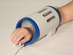
21 B1 - : RF Receive Goal: High sensitivity, spatially limited, low noise Birdcage coils Uniform B1 - but single channel Surface coils Varying B1 - but high sensitivity Coil arrays Multiple channels with Varying B1 - Allows some spatial localization: Parallel Imaging 21


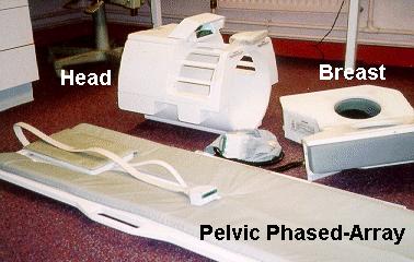

22 RF Coils 22
23 Receiver System 500 to 1000 k samples/s Complex sampling Low-pass filter capability Typically channels Time-varying frequency and phase modulation (Typically single-channel) 23
24 Gradients Goal: Strong, switchable, linear Bz variation with x,y,z Peak amplitude ~ mt/m (~ 200A) Switching 200 mt/m/ms (~1500 V) Limits: Amplifier power, heating, coil heating db/dt limitation due to peripheral nerve stimulation Switching induces Eddy Currents Concomitant terms (Bx and By variations) Non-linearities (often correctable) 24
25 Gradient Waveforms Mapping of position to frequency, slope = γg Typically waveforms are trapezoidal Constant amplitude and slew-rate limits Frequency G read Amplitude Time Position 25
26 Shims Goal usually to make B0 more uniform with subject Center frequency Linear shims (Up to ~1% offset to gradients) Higher-order (HO) shims (Spherical Harmonics) Shim arrays, Shim+RF (Current Research) Usually HO shims not dynamically switchable 26
27 Review Questions Which field is the receive field? B1 - Which field is always on? B0 What receive bandwidth corresponds to 500,000 samples/second? ±250 khz Why might small surface coils (or arrays) be useful? High sensitivity, Low noise, Spatially limiting 27
28 Image Formation and k-space Gradients and phase Signal equation Sampling / Aliasing Parallel Imaging Many reconstruction methods in EE369C 28
29 Gradient Strength and Sign Positive Gradient x Negative Gradient Double Strength Half-Duration x x Can control both amplitude and duration 29
30 Gradient Along Both x and y y Gx Gy x Can also vary along z 30
31 Ribbon Analogy x Gradients induce phase twist Twist has a number of cycles and a sign Twist can be along any direction 31
32 Gradients and Phase Control gradient amplitude and duration Can control frequency: Frequency = γ(gx x + Gy y) Can encode phase over duration t Angle = γt (Gx x + Gy y + Gz z) Z Z Generally: = (x G x dt + y G y dt) = (x Z Z G x dt + y G y dt) What are the units of Frequency and Angle (φ) here? 32
33 Signal Equations For a single spin: = (x Z G x dt + y Z G y dt) Represent as exponential: s = e i (x R G x dt+y R G y dt) Sum over many spins: Signal equation: s = Z 1 Z s = Z 1 Z (x, y)e 2 i(k xx+k y y) dxdy (x, y)e i (x R G x dt+y R G y dt) dxdy k x,y (t) = 2 Z t s(t) =FT[ (x, y)] kx (t),k y (t) 0 G x,y ( )d 33
34 Fourier Transform in MRI s(t) =FT[ (x, y)] kx (t),k y (t) M(k) Fourier Transform ρ(r) Given M(k) at enough k locations, we can find ρ(r) It does not matter how we got to k! What are the units of kx(t) and ky(t)? 34
35 Fourier Encoding and Reconstruction Encoding k y x Sum over image k x Reconstruction k y Gradient-induced Phase k-space k x x Sum over k-space k-space Spatial Harmonic 35


36 k-space: Spatial Frequency Map k y k-space k x In terms of pixel-width, what is the width of k-space? 36


37 Image Formation and Sampling Readout Gradient time Phase-Encode Gradient time k read k phase 37 k-space Readout Direction
")
38 k space Extent and Image Resolution Data Acquisition k space Image Space Fourier Transform x =1/(2k max ) 38


39 Sampling and Field of View Sampling density determines FOV Sparse sampling results in aliasing Phase-Encode FOV =1/ k y Readout FOV FOV k read k read k phase k phase 39
40 Phase-Encoding with Two Coils k y k-space k x 40
41 Readout Parameters Bandwidth linked to readout half-bandwidth (GE) = 0.5 x sample rate Same as Filter bandwidth (baseband) Pixel-bandwidth often useful Frequency G read Bandwidth per Pixel Full Bandwidth BW pix = G read x BW half = G read FOV/2 FOV Pixel Position 41
42 Imaging Example Desired Image Parameters: 256 x 256, over 25cm FOV (±)125 khz bandwidth What are the... Sampling period? Readout duration? Gradient strength? Bandwidth per pixel? k-space extent? 1/(2*125kHz) = 4µs 4µs * 256 = 1ms 250kHz / 0.25m / 42.58kHz/mT 23 mt/m (2.3 G/cm) 250kHz/256 pix = ~ 1kHz/pixel 0.5 / 1mm = 0.5 mm -1 = 5cm -1 42
43 2D Multislice vs 3D Slab Imaging 2D 3D Shorter scan times, reduced motion artifact Continuous coverage Thinner slices, reformats 43
44 Imaging Summary Gradients impose time-varying linear phase k-space is time-integral of gradients k-space samples Fourier Transform to/from image Density of k-space <> FOV (image extent) Extent of k-space <> Resolution (image density) 3D k-space is possible Parallel imaging uses coils to extend FOV 44
45 Excitation General principles of excitation Selective Excitation with gradients Relationships for slice excitation Excitation k-space Much more covered in EE469B 45
46 Excitation: B1 Field Direction of B1 is perpendicular to B0 Magnetization precesses about B1 Turn on and off B1 to tip magnetization Problem: We can t turn off B0! Precession still around B0 46
47 Excitation Magnetization precesses about net field (B 0 +B 1 ) B 1 << B 0 Must tune B 1 frequency to Larmor frequency B 1 B 0 Magnetization Static B 1 Field Rotating B 1 Field 47
48 Excitation: Rotating Frame Excite spins out of their equilibrium state. B 1 << B 0 Transverse RF field (B 1 ) rotates at γb 0 about z-axis. B 1 B 0 Magnetization Static Frame Rotating Frame, On resonance 48
49 Position Selective Excitation Slope = 1 γ G Frequency 49
50 Selective Excitation Position Slope = 1 γ G Larmor Frequency Slice width = BWRF / γgz Slice center = Frequency / γgz Magnitude RF Amplitude = + + B 1 Frequency Time 50
51 Excitation Example Given a 2 khz RF pulse bandwidth, and desired 5mm thick slice Slices at -2cm, 0, 2cm What are the... Gradient strength? (γ/2π)gz Excitation frequencies? 2kHz/5mm = 400kHz/m ~ 9.4 mt/m (0.94 G/cm) BW/slice = 2kHz/5mm, so -8, 0, 8 khz (9.4/50)*5mm ~1mm slice Thinnest slice possible with 50mT/m max gradients? 51
52 Excitation k-space Excitation k-space goes backwards from end of RF/ gradient pair: k e (t) = 2 Z T t Excited profile = Fourier Transform of excitation k-space Central flip angle = area under pulse (may be zero!): = G( )d Z B 1 ( )d k r (t) = 2 Z t 0 G( )d 52
53 Excitation Example For a 1ms, constant RF pulse of amplitude 10µT What is the flip angle? (42.58 khz/mt)(0.01mt)(1ms) = cycles = 153º How does RF energy change if the duration is halved and amplitude doubled? Doubles - (2A) 2 (T/2) = 2(A 2 T) 53
")
54 Signals and Contrast Simple Bloch Equation Solutions Basic contrast mechanisms: T1, T2, IR, Steady-State T2-Weighted T2-w FLAIR T1-w FLAIR Gradient Echo Diffusion-Weighted Apparent Diffusion Coefficient (ADC) 54
55 Signals and Contrast Bloch Equation Solutions (Relaxation): M xy (t) =M xy (0)e t/t 2 M z (t) =M 0 +[M z (0) M 0 ]e t/t 1 M z M0 0 M0 time Rotations due to excitation: Mxy 0 time M 0 xy = M xy cos + M z sin M 0 z = M z cos M xy sin 55
56 Echo Time (TE): T2 weighting 90º 90º RF 1 TE = Time from RF to echo Signal M z 0 Short TE Long TE 56


57 T2 Contrast TE = 20 Signal TE = 40 TE = 60 TE = 80 Echo Time (ms) Dardzinski BJ, et al. Radiology, 205: ,
58 Repetition Time (TR) : T 1 Weighting 90º 90º RF 90º 1 M z Signal M z 0 M xy Each excitation starts with reduced M z 58
59 T1-Weighted Spin Echo Short Repetition Long Repetition Signal Signal Bone Time Joint Fluid Time 59
 Full Recovery Signal Decay T2 Weighting 60 Images Courtesy of Anne")
60 Basic Contrast Question (TE, TR) Short TE Incomplete Recovery Minimal Decay T1 Weighting Short TR Full Recovery Minimal Decay Proton Density Weighting Long TR Long TE Incomplete Recovery Signal Decay Mixed Contrast (Not used much) Full Recovery Signal Decay T2 Weighting 60 Images Courtesy of Anne Sawyer
61 RF Inversion-Recovery TI 180º 180º 1 Signal 0-1 Fat suppression based on T 1 Short TI Inversion Recovery (STIR) 61

62 Long Inversion Time (TI) - FLAIR Long TI suppresses fluid signal 62
63 RF Signal Question TR TI 180º 90º 180º TE Inversion Recovery Sequence: TR = 1s, TI = 0.5s, TE=50ms What is the signal for T1=0.5s, T2=100ms? Signal (Mxy) decays to 0 At TI, Mz-M0 = 1.63 exp(-1) Mz does not fully recover Mz ~ 0.4 M0 exp(-1) = 037 T2 decay ~ exp(-0.5) ~ 0.6 Mz is 0.63 M0 before 180º Signal = 0.4 x 0.6 = 0.24 M0 63
64 Steady-State Sequences Repeated sequences always lead to a steady state Sometimes includes equilibrium (easier) Otherwise trace magnetization and solve equations Example: Small-tip, TE=0 TR TE M z (TE)=M z (TR) cos M z (TR)=M 0 +[M z (TE) M 0 ]e TR/T 1... Combining... M z (TR)=M 0 1 e TR/T 1 1 e TR/T 1 cos 64
65 Summary ~ Background I Overview of NMR Hardware Image formation and k-space Excitation k-space Signals and contrast 65
Background (~EE369B)
") Background (~EE369B) Magnetic Resonance Imaging D. Nishimura Overview of NMR Hardware Image formation and k-space Excitation k-space Signals and contrast Signal-to-Noise Ratio (SNR) Pulse Sequences 13
Background (~EE369B) Magnetic Resonance Imaging D. Nishimura Overview of NMR Hardware Image formation and k-space Excitation k-space Signals and contrast Signal-to-Noise Ratio (SNR) Pulse Sequences 13
Pulse Sequences: Rapid Gradient Echo
 Pulse Sequences: Rapid Gradient Echo M229 Advanced Topics in MRI Holden H. Wu, Ph.D. 2018.04.17 Department of Radiological Sciences David Geffen School of Medicine at UCLA Class Business Office hours -
H 2 O and fat imaging
 H 2 O and fat imaging Xu Feng Outline Introduction benefit from the separation of water and fat imaging Chemical Shift definition of chemical shift origin of chemical shift equations of chemical shift
EE225E/BIOE265 Spring 2014 Principles of MRI. Assignment 6. Due Friday March 7th, 2014, Self Grading Due Monday March 10th, 2014
 EE225E/BIOE265 Spring 2014 Principles of MRI Miki Lustig 1. Read Nishimura Ch. 6 Assignment 6 Due Friday March 7th, 2014, Self Grading Due Monday March 10th, 2014 2. Nishimura assignment 6.5 3. Mimimum-Phase
Principles of MRI EE225E / BIO265. Lecture 21. Instructor: Miki Lustig UC Berkeley, EECS. M. Lustig, EECS UC Berkeley
 Principles of MRI Lecture 21 EE225E / BIO265 Instructor: Miki Lustig UC Berkeley, EECS Question What is the difference between the images? Answer Both T1-weighted spin-echo gradient-echo Lower SNR Meniscus
Module 2. Artefacts and Imaging Optimisation for single shot methods. Content: Introduction. Phase error. Phase bandwidth. Chemical shift review
 MRES 7005 - Fast Imaging Techniques Module 2 Artefacts and Imaging Optimisation for single shot methods Content: Introduction Phase error Phase bandwidth Chemical shift review Chemical shift in pixels
EE225E/BIOE265 Spring 2012 Principles of MRI. Assignment 7. Due March 16, 2012
 EE225E/BIOE265 Spring 2012 Principles of MRI Miki Lustig Assignment 7 Due March 16, 2012 1. From Midterm I 2010: You ve just programmed up your first 2DFT pulse sequence, and are trying it out on the scanner.
Pulse Sequence Design Made Easier
 Pulse Sequence Design Made Easier Gregory L. Wheeler, BSRT(R)(MR) MRI Consultant gurumri@gmail.com 1 2 Pulse Sequences generally have the following characteristics: An RF line characterizing RF Pulse applications
Pulse Sequence Design and Image Procedures
 Pulse Sequence Design and Image Procedures 1 Gregory L. Wheeler, BSRT(R)(MR) MRI Consultant 2 A pulse sequence is a timing diagram designed with a series of RF pulses, gradients switching, and signal readout
M R I Physics Course. Jerry Allison Ph.D., Chris Wright B.S., Tom Lavin B.S., Nathan Yanasak Ph.D. Department of Radiology Medical College of Georgia
 M R I Physics Course Jerry Allison Ph.D., Chris Wright B.S., Tom Lavin B.S., Nathan Yanasak Ph.D. Department of Radiology Medical College of Georgia M R I Physics Course Magnetic Resonance Imaging Spatial
EE225E/BIOE265 Spring 2011 Principles of MRI. Assignment 6 Solutions. (y 0 + vt) dt. 2 y 0T + 3 )
 dt. 2 y 0T + 3 )") EE225E/BIOE265 Spring 211 Principles of MRI Miki Lustig Handout Assignment 6 Solutions 1. Nishimura 6.7 (Thanks Galen!) a) After the 9 y pulse, the spin is in the ˆx direction (using left-handed rotations).
EE225E/BIOE265 Spring 211 Principles of MRI Miki Lustig Handout Assignment 6 Solutions 1. Nishimura 6.7 (Thanks Galen!) a) After the 9 y pulse, the spin is in the ˆx direction (using left-handed rotations).
2015 Spin echoes and projection imaging
 1. Spin Echoes 1.1 Find f0, transmit amplitudes, and shim settings In order to acquire spin echoes, we first need to find the appropriate scanner settings using the FID GUI. This was all done last week,
RF pulse design and the Small Tip Angle Approximation
 RF pulse design and the Small Tip Angle Approximation Dr Shaihan J Malik Lecturer in Imaging Sciences Division of Imaging Sciences & Biomedical Engineering King s College London shaihan.malik@kcl.ac.uk
System/Imaging Imperfections
 System/Imaging Imperfections B0 variations: Shim, Susceptibility B1 variations: Transmit, Receive Gradient Imperfections: Non-linearities Delays and Eddy currents Concomitant terms 1 B0 Variations - Off-Resonance
(N)MR Imaging. Lab Course Script. FMP PhD Autumn School. Location: C81, MRI Lab B0.03 (basement) Instructor: Leif Schröder. Date: November 3rd, 2010
MR Imaging. Lab Course Script. FMP PhD Autumn School. Location: C81, MRI Lab B0.03 (basement) Instructor: Leif Schröder. Date: November 3rd, 2010") (N)MR Imaging Lab Course Script FMP PhD Autumn School Location: C81, MRI Lab B0.03 (basement) Instructor: Leif Schröder Date: November 3rd, 2010 1 Purpose: Understanding the basic principles of MR imaging
(N)MR Imaging Lab Course Script FMP PhD Autumn School Location: C81, MRI Lab B0.03 (basement) Instructor: Leif Schröder Date: November 3rd, 2010 1 Purpose: Understanding the basic principles of MR imaging
EE469B: Assignment 1 Solutions
 EE469B Fall 26-7 RF Pulse Design for MRI EE469B: Assignment Solutions Due Thursday Oct 6 Introduction This assignment concerns typical Fourier transform designs of excitation pulses. This includes designing
Half-Pulse Excitation Pulse Design and the Artifact Evaluation
 Half-Pulse Excitation Pulse Design and the Artifact Evaluation Phillip Cho. INRODUCION A conventional excitation scheme consists of a slice-selective RF excitation followed by a gradient-refocusing interval
Lab 8 6.S02 Spring 2013 MRI Projection Imaging
 1. Spin Echos 1.1 Find f0, TX amplitudes, and shim settings In order to acquire spin echos, we first need to find the appropriate scanner settings using the FID GUI. This was all done last week, but these
MAGNETIC RESONANCE IMAGING
 CSEE 4620 Homework 3 Fall 2018 MAGNETIC RESONANCE IMAGING 1. THE PRIMARY MAGNET Magnetic resonance imaging requires a very strong static magnetic field to align the nuclei. Modern MRI scanners require
Gradient Spoiling. Average balanced SSFP magnetization Reduce sensitivity to off-resonance. FFE, FISP, GRASS, GRE, FAST, Field Echo
 Gradient Spoiling Average balanced SSFP magnetization Reduce sensitivity to off-resonance FFE, FISP, GRASS, GRE, FAST, Field Echo 1 Gradient-Spoiled Sequence (GRE, FFE, FISP, GRASS) RF TR G z G y G x Signal
k y 2k y,max k x 2k x,max
 EE225E/BIOE265 Spring 2012 Principles of MRI Miki Lustig Assignment 5 Due Feb 26, 2012 1. Finish reading Nishimura Ch. 5. 2. For the 16 turn spiral trajectory, plotted below, what is the a) Spatial resolution,
MRI: From Signal to Image
 MRI: From Signal to Image Johannes Koch physics654 2013-05-06 1 / 27 Tomography Magnetic Resonance Tomography Tomography: tomos: section graphein: to write Signal measured as function of space 2 / 27 Tomography
RF Pulse Toolkit: Application Specific Design
 RF Pulse Toolkit: Application Specific Design William A Grissom Department of Biomedical Engineering, Vanderbilt University, Nashville, TN, USA will.grissom@vanderbilt.edu Introduction RF excitation is
MR Basics: Module 6 Pulse Sequences
 Module 6 Transcript For educational and institutional use. This transcript is licensed for noncommercial, educational inhouse or online educational course use only in educational and corporate institutions.
Advanced MSK MRI Protocols at 3.0T. Garry E. Gold, M.D. Associate Professor Department of Radiology Stanford University
 Advanced MSK MRI Protocols at 3.0T Garry E. Gold, M.D. Associate Professor Department of Radiology Stanford University Outline Why High Field for MSK? SNR and Relaxation Times Technical Issues Example
10. Phase Cycling and Pulsed Field Gradients Introduction to Phase Cycling - Quadrature images
 10. Phase Cycling and Pulsed Field Gradients 10.1 Introduction to Phase Cycling - Quadrature images The selection of coherence transfer pathways (CTP) by phase cycling or PFGs is the tool that allows the
EE469B: Assignment 2 Solutions
 EE469B Fall 26-7 RF Pulse Design for MRI EE469B: Assignment 2 s Due Thursday Oct 3 Introduction This assignment concerns the design of small-tip-angle 2D excitation pulses based on spiral k-space trajectories.
EE469B: Assignment 4 Solutions
 EE469B Fall 26-7 RF Pulse Design for MRI EE469B: Assignment 4 Solutions Due Thursday Oct 27. True Null/Flyback Spectral-Spatial Pulses True null and flyback designs are very closely related. In this problem
NMR Basics. Lecture 2
 NMR Basics Lecture 2 Continuous wave (CW) vs. FT NMR There are two ways of tuning a piano: - key by key and recording each sound (or frequency). - or, kind of brutal, is to hit with a sledgehammer and
Cardiac MR. Dr John Ridgway. Leeds Teaching Hospitals NHS Trust, UK
 Cardiac MR Dr John Ridgway Leeds Teaching Hospitals NHS Trust, UK Cardiac MR Physics for clinicians: Part I Journal of Cardiovascular Magnetic Resonance 2010, 12:71 http://jcmr-online.com/content/12/1/71
Lecture 7: Basics of magnetic resonance imaging (MRI): one dimensional Fourier imaging
: one dimensional Fourier imaging") Lecture 7: Basics of magnetic resonance imaging (MRI): one dimensional Fourier imaging Lecture aims to explain: 1. Basic aims of magnetic resonance imaging 2. Signal demodulation in magnetic resonance
Lecture 7: Basics of magnetic resonance imaging (MRI): one dimensional Fourier imaging Lecture aims to explain: 1. Basic aims of magnetic resonance imaging 2. Signal demodulation in magnetic resonance
MRI SYSTEM COMPONENTS Module One
 MRI SYSTEM COMPONENTS Module One 1 MAIN COMPONENTS Magnet Gradient Coils RF Coils Host Computer / Electronic Support System Operator Console and Display Systems 2 3 4 5 Magnet Components 6 The magnet The
1 Introduction. 2 The basic principles of NMR
 1 Introduction Since 1977 when the first clinical MRI scanner was patented nuclear magnetic resonance imaging is increasingly being used for medical diagnosis and in scientific research and application
Gradients. Effects of B0 gradients on transverse magnetisation Similar to figure 10 of Sattler review Progr. NMR 34 (1999), 93
, 93") Gradients 1. What are gradients? Modern high-resolution NMR probes contain -besides the RF coils - additional coils that can be fed a DC current. The coils are built so that a pulse (~1 ms long) of DC
Gradients 1. What are gradients? Modern high-resolution NMR probes contain -besides the RF coils - additional coils that can be fed a DC current. The coils are built so that a pulse (~1 ms long) of DC
RF Pulse Design. Multi-dimensional Excitation II. M229 Advanced Topics in MRI Kyung Sung, Ph.D Class Business
 RF Pulse Design Multi-dimensional Excitation II M229 Advanced Topics in MRI Kyung Sung, Ph.D. 2018.04.12 Class Business - Homework 1 will be due on 4/26 - Office hours Instructors: Fri 10-12 noon TAs:
functional MRI: A primer
 Activation Leads to: functional MRI: A primer CBF Increased +ΔR CBV Increased +ΔR (C+) O Utilization Increased slightly? Venous [O ] Increased -ΔR* Glucose Utilization Increased? Lactate BOLD R=/T R=/T
NIH Public Access Author Manuscript Magn Reson Med. Author manuscript; available in PMC 2010 July 21.
 NIH Public Access Author Manuscript Published in final edited form as: Magn Reson Med. 2010 April ; 63(4): 1092 1097. doi:10.1002/mrm.22223. Spatially Varying Fat-Water Excitation Using Short 2DRF Pulses
2014 M.S. Cohen all rights reserved
 2014 M.S. Cohen all rights reserved mscohen@g.ucla.edu IMAGE QUALITY / ARTIFACTS SYRINGOMYELIA Source http://gait.aidi.udel.edu/res695/homepage/pd_ortho/educate/clincase/syrsco.htm Surgery is usually recommended
RF and Electronic Design Perspective on Ultra-High Field MRI systems
 RF and Electronic Design Perspective on Ultra-High Field MRI systems A DISSERTATION SUBMITTED TO THE FACULTY OF THE GRADUATE SCHOOL OF THE UNIVERSITY OF MINNESOTA BY SUNG-MIN SOHN IN PARTIAL FULFILLMENT
Improving high-field MRI using parallel excitation
 review Improving high-field MRI using parallel excitation MRI at high magnetic field strengths promises to deliver clearer images of the body s structure and function. However, high-field MRI currently
Spiral MRI on a 9.4T Vertical-bore Superconducting Magnet Using Unshielded and Self-shielded Gradient Coils
 Magn Reson Med Sci doi:10.2463/mrms.tn.2016-0049 Published Online: March 27, 2017 TECHNICAL NOTE Spiral MRI on a 9.4T Vertical-bore Superconducting Magnet Using Unshielded and Self-shielded Gradient Coils
MR in RTP. MR Data for Treatment Planning: Spatial Accuracy Issues, Protocol Optimization, and Applications (Preview of TG117 Report) Acknowledgements
 Acknowledgements") MR Data for Treatment Planning: Issues, Protocol Optimization, and s (Preview of TG117 Report) Debra H. Brinkmann Mayo Clinic, Rochester MN Acknowledgements TG-117 Use of MRI Data in Treatment Planning
MR Data for Treatment Planning: Issues, Protocol Optimization, and s (Preview of TG117 Report) Debra H. Brinkmann Mayo Clinic, Rochester MN Acknowledgements TG-117 Use of MRI Data in Treatment Planning
Image Quality/Artifacts Frequency (MHz)
") The Larmor Relation 84 Image Quality/Artifacts (MHz) 42 ω = γ X B = 2πf 84 0.0 1.0 2.0 Magnetic Field (Tesla) 1 A 1D Image Magnetic Field Gradients Magnet Field Strength Field Strength / Gradient Coil
The Larmor Relation 84 Image Quality/Artifacts (MHz) 42 ω = γ X B = 2πf 84 0.0 1.0 2.0 Magnetic Field (Tesla) 1 A 1D Image Magnetic Field Gradients Magnet Field Strength Field Strength / Gradient Coil
MRI Metal Artifact Reduction
 MRI Metal Artifact Reduction PD Dr. med. Reto Sutter University Hospital Balgrist Zurich University of Zurich OUTLINE Is this Patient suitable for MR Imaging? Metal artifact reduction Is this Patient suitable
3D-Printed Microstrip Resonators for 4.7T MRI. Saeed Javidmehr. A thesis submitted in partial fulfillment of the requirements for the degree of
 3D-Printed Microstrip Resonators for 4.7T MRI by Saeed Javidmehr A thesis submitted in partial fulfillment of the requirements for the degree of Master of Science in Electromagnetics and Microwaves Department
HETERONUCLEAR IMAGING. Topics to be Discussed:
 HETERONUCLEAR IMAGING BioE-594 Advanced MRI By:- Rajitha Mullapudi 04/06/2006 Topics to be Discussed: What is heteronuclear imaging. Comparing the hardware of MRI and heteronuclear imaging. Clinical applications
A Conceptual Tour of Pulsed NMR*
 A Conceptual Tour of Pulsed NMR* Many nuclei, but not all, possess both a magnetic moment, µ, and an angular momentum, L. Such particles are said to have spin. When the angular momentum and magnetic moment
MR Basics: Module 8 Image Quality
 Module 8 Transcript For educational and institutional use. This transcript is licensed for noncommercial, educational inhouse or online educational course use only in educational and corporate institutions.
Chapter 2. The Physics of Magnetic Resonance Imaging
 Chapter 2. The Physics of Magnetic Resonance Imaging 2.1. Introduction The origins of the Nuclear Magnetic Resonance (NMR) signal and how it is manipulated to form images are the subjects of this chapter.
Echo-Planar Imaging for a 9.4 Tesla Vertical-Bore Superconducting Magnet Using an Unshielded Gradient Coil
 Magn Reson Med Sci, Vol. XX, No. X, pp. XXX XXX, 2015 2016 Japanese Society for Magnetic Resonance in Medicine TECHNICAL NOTE by J-STAGE doi:10.2463/mrms.tn.2015-0123 Echo-Planar Imaging for a 9.4 Tesla
MR in Tx Planning. Acknowledgements. Outline. Overview MR in RTP
 MR Data for Treatment Planning and Stereotactic Procedures: Sources of Distortion, Protocol Optimization, and Assessment (Preview of TG117 Report) Debra H. Brinkmann Mayo Clinic, Rochester MN Acknowledgements
6.S02 MRI Lab Acquire MR signals. 2.1 Free Induction decay (FID)
") 6.S02 MRI Lab 1 2. Acquire MR signals Connecting to the scanner Connect to VMware on the Lab Macs. Download and extract the following zip file in the MRI Lab dropbox folder: https://www.dropbox.com/s/ga8ga4a0sxwe62e/mit_download.zip
6.S02 MRI Lab 1 2. Acquire MR signals Connecting to the scanner Connect to VMware on the Lab Macs. Download and extract the following zip file in the MRI Lab dropbox folder: https://www.dropbox.com/s/ga8ga4a0sxwe62e/mit_download.zip
High Field MRI: Technology, Applications, Safety, and Limitations
 High Field MRI: Technology, Applications, Safety, and Limitations R. Jason Stafford, Ph.D. The University of Texas M. D. Anderson Cancer Center, Houston, TX Introduction The amount of available signal
Weber State University Radiologic Technology 4603
 Weber State University Radiologic Technology 4603 MRI Physics and Instrumentation Instructor: Rex T. Christensen MHA R.T. (R) (MR) (CT) (ARRT) CIIP Contact Info: E-mail: rexchristensen@weber.edu Phone:
Mapping the Flip Angle in Magnetic Resonance Imaging Using the Accelerated 3D Look-Locker Sequence
 Western University Scholarship@Western Electronic Thesis and Dissertation Repository January 2011 Mapping the Flip Angle in Magnetic Resonance Imaging Using the Accelerated 3D Look-Locker Sequence Trevor
Steady-state sequences: Spoiled and balanced methods
 Steady-state sequences: Spoiled and balanced methods Karla L Miller, FMRIB Centre, University of Oxford What is steady-state imaging? In the context of MRI pulse sequences, the term steady state typically
2 Hardware for Magnetic Resonance Imaging
 Hardware for Magnetic Resonance Imaging 13 2 Hardware for Magnetic Resonance Imaging Kenneth W. Fishbein, Joseph C. McGowan, and Richard G. Spencer CONTENTS 2.1 Introduction 13 2.2 Magnets 13 2.2.1 Permanent
MRI Summer Course Lab 2: Gradient Echo T1 & T2* Curves
 MRI Summer Course Lab 2: Gradient Echo T1 & T2* Curves Experiment 1 Goal: Examine the effect caused by changing flip angle on image contrast in a simple gradient echo sequence and derive T1-curves. Image
Magnetic Resonance Imaging (MRI)
") C. A. Bouman: Digital Image Processing - February 15, 2 1 Magnetic Resonance Imaging (MRI) Can be very high resolution No radiation exposure Very flexible and programable Tends to be expensive, noisy,
C. A. Bouman: Digital Image Processing - February 15, 2 1 Magnetic Resonance Imaging (MRI) Can be very high resolution No radiation exposure Very flexible and programable Tends to be expensive, noisy,
PHY3902 PHY3904. Nuclear magnetic resonance Laboratory Protocol
 PHY3902 PHY3904 Nuclear magnetic resonance Laboratory Protocol PHY3902 PHY3904 Nuclear magnetic resonance Laboratory Protocol GETTING STARTED You might be tempted now to put a sample in the probe and try
Encoding of inductively measured k-space trajectories in MR raw data
 Downloaded from orbit.dtu.dk on: Apr 10, 2018 Encoding of inductively measured k-space trajectories in MR raw data Pedersen, Jan Ole; Hanson, Christian G.; Xue, Rong; Hanson, Lars G. Publication date:
IR/SR TrueFISP. Works-in-Progress package Version 1.2. For the SIEMENS Magnetom. Installation and User s Guide NUMARIS/4VA21B.
 Works-in-Progress package Version 1.2 For the Installation and User s Guide NUMARIS/4VA21B January 22, 2003 Section of Medical Physics, University Hospital Freiburg, Germany Contact: Klaus Scheffler PhD
The Pulsed Resistive Low-Field MR Scanner
 39 Chapter 3 The Pulsed Resistive Low-Field MR Scanner 3.1 Background In the remaining part of this work we are going to describe hyperpolarized gas relaxation, diffusion and MR imaging experiments. These
SIEMENS MAGNETOM Skyra syngo MR D13
 Page 1 of 12 SIEMENS MAGNETOM Skyra syngo MR D13 \\USER\CIND\StudyProtocols\PTSA\*ep2d_M0Map_p2_TE15 TA:7.9 s PAT:2 Voxel size:2.5 2.5 3.0 mm Rel. SNR:1.00 :epfid Properties Routine Contrast Prio Recon
Magnetic Resonance Imaging Principles, Methods, and Techniques
 Magnetic Resonance Imaging Principles, Methods, and Techniques Perry Sprawls Jr., Emory University Publisher: Medical Physics Publishing Corporation Publication Place: Madison, Wisconsin Publication Date:
In a typical biological sample the concentration of the solute is 1 mm or less. In many situations,
 Water suppression n a typical biological sample the concentration of the solute is 1 mm or less. n many situations, the signals of interest are those of amide protons that exchange with the solvent water.
A. SPECIFIC AIMS: phase graph (EPG) algorithms to cover a wide range of MRI
 algorithms to cover a wide range of MRI") A. SPECIFIC AIMS: A.. Overview: The promise of improved MRI results at high field strength is compromised by the difficulties encountered at high field, including: i) Non-uniform excitation, due to the
A. SPECIFIC AIMS: A.. Overview: The promise of improved MRI results at high field strength is compromised by the difficulties encountered at high field, including: i) Non-uniform excitation, due to the
Magnetic Resonance Imaging
 Magnetic Resonance Imaging Principles, Methods, and Techniques Perry Sprawls, Ph.D., FACR, FAAPM, FIOMP Distinguished Emeritus Professor Department of Radiology Emory University Atlanta, Georgia Medical
INSTRUMENTATION FOR PARALLEL MAGNETIC RESONANCE IMAGING. A Dissertation DAVID GERALD BROWN
 INSTRUMENTATION FOR PARALLEL MAGNETIC RESONANCE IMAGING A Dissertation by DAVID GERALD BROWN Submitted to the Office of Graduate Studies of Texas A&M University in partial fulfillment of the requirements
PULSED NUCLEAR MAGNETIC RESONANCE. Advanced Laboratory, Physics 407 University of Wisconsin Madison, Wisconsin 53706
 (revised, 2/12/07) PULSED NUCLEAR MAGNETIC RESONANCE Advanced Laboratory, Physics 407 University of Wisconsin Madison, Wisconsin 53706 Abstract A pulsed nuclear magnetic resonance technique (spin-echo)
The promise of high-field MRI. High Field MRI Technology, Applications, Safety, and Limitations. High-field Scanners
 High Field MRI Technology, Applications, Safety, and Limitations R. Jason Stafford, Ph.D. Department of Imaging Physics The University of Texas M. D. Anderson Cancer Center Houston, TX The promise of high-field
H Micro-Imaging. Tuning and Matching. i. Open any 1H data set and type wobb.
 - 1-1 H Micro-Imaging The NMR-specific properties of the objects are visualized as multidimensional images. Translational motion can be observed and spectroscopic information can be spatially resolved.
3T Unlimited. ipat on MAGNETOM Allegra The Importance of ipat at 3T. medical
 3T Unlimited ipat on MAGNETOM Allegra The Importance of ipat at 3T s medical ipat on MAGNETOM Allegra The Importance of ipat at 3T The rise of 3T MR imaging Ultra High Field MR (3T) has flourished during
MRI Systems and Coil Technology
 MRI for Technologists MRI Systems and Coil Technology PROGRAM INFORMATION MRI for Technologists is a training program designed to meet the needs of radiologic technologists entering or working in the field
Simultaneous Multi-Slice (Slice Accelerated) Diffusion EPI
 Diffusion EPI") Simultaneous Multi-Slice (Slice Accelerated) Diffusion EPI Val M. Runge, MD Institute for Diagnostic and Interventional Radiology Clinics for Neuroradiology and Nuclear Medicine University Hospital Zurich
Simultaneous Multi-Slice (Slice Accelerated) Diffusion EPI Val M. Runge, MD Institute for Diagnostic and Interventional Radiology Clinics for Neuroradiology and Nuclear Medicine University Hospital Zurich
Localization of microscale devices in vivo using addressable transmitters operated as magnetic spins
 SUPPLEMENTARY INFORMATION Articles DOI: 10.1038/s41551-017-0129-2 In the format provided by the authors and unedited. Localization of microscale devices in vivo using addressable transmitters operated
MRI Anatomy and Positioning Series Module 12: Fat Suppression Techniques
 MRI Anatomy and Positioning Series Module 12: Fat Suppression Techniques 1 Introduction... 3 RF FatSat... 4 HOAST... 4 FatSat... 5 Segment FS... 8 PhaseCycle... 9 Water Excitation... 10 STIR... 12 FatSep...
Hardware. MRI System. MRI system Multicoil Microstrip. Part1
 Hardware MRI system Multicoil Microstrip MRI System Part1 1 The MRI system is made up of a variety of subsystems. the Operator Workspace Gradient Driver subsystem The Physiological Acquisition Controller
Your first NMR measurement
 Your first NMR measurement Introduction Select 10mM water in D2O as NMR sample. The NMR spectrum of such sample consists of only two signals: the water signal and the peak of the reference (TSP). Follow
EE225E/BIOE265 Spring 2013 Principles of MRI. Assignment 3. x 2 + y 2 0
 EE225E/BIOE265 Spring 213 Principles of MRI Miki Lustig Assignment 3 1 Finish reading Ch 4 2 Nishimura, Q 33 Solutions: 2D circularly symmetric objects can be expressed as m(r) and, G r = db z dr, r =
Page 1 of 9. Protocol: adult_other_adni3_study_human_ge_3t_25w_ _ _1. 3 Plane Localizer. 3 Plane Localizer PATIENT POSITION
 3 Localizer FOV 26.0 Slice Thickness 5.0 Slice Spacing 0.0 Freq 256 Phase 128 3-PLANE 3 Localizer Unswap Phase Correction Gradient Echo Imaging Options Seq, Fast Recon All Images Contrast Yes/ 3 Localizer
Introduction to MR Hardware. RF Coils C M L C T. = g * B 0. Rotating magnetization produces alternating magnetic field
 Introduction to MR Hardware RF Coils Dominik v. Elverfeldt Sep 5 th 2012 Courtesy of Hans Weber, Freiburg C M R = 50 Transmission = B 0 Reception L C T R Oscillating with Lamor frequency. B 1 field perpendicular
1.5T HIGH FIELD SMALL ANIMAL MRI
 1.5T HIGH FIELD SMALL ANIMAL MRI Designed Specifically for Veterinarians TECHNICAL GUIDE ADVANCING THE ART AND SCIENCE OF VETERINARY MRI The PetVet is the only high-field MRI system designed specifically
Supplementary Figure 1. Scanning Electron Microscopy images of the pristine electrodes. (a) negative electrode and (b) positive electrode.
 negative electrode and (b) positive electrode.") a b Supplementary Figure 1. Scanning Electron Microscopy images of the pristine electrodes. (a) negative electrode and (b) positive electrode. Images were performed using a FEI/Philips XL4 microscope with
a b Supplementary Figure 1. Scanning Electron Microscopy images of the pristine electrodes. (a) negative electrode and (b) positive electrode. Images were performed using a FEI/Philips XL4 microscope with
Radio Frequency Detector Arrays for High-Field Magnetic Resonance Imaging
 Radio Frequency Detector Arrays for High-Field Magnetic Resonance Imaging by Atefeh Kordzadeh A thesis submitted in partial fulfillment of the requirements for the degree of Doctor of Philosophy Departments
Waveform Encoding - PCM. BY: Dr.AHMED ALKHAYYAT. Chapter Two
 Chapter Two Layout: 1. Introduction. 2. Pulse Code Modulation (PCM). 3. Differential Pulse Code Modulation (DPCM). 4. Delta modulation. 5. Adaptive delta modulation. 6. Sigma Delta Modulation (SDM). 7.
Nuclear Magnetic Resonance (NMR)
") California Institute of Technology Physics 77 Nuclear Magnetic Resonance (NMR) Eric D. Black October 3, 2008 1 Theory Read Section 14.4 of Shankar, Spin Dynamics, including the optional digression on negative
California Institute of Technology Physics 77 Nuclear Magnetic Resonance (NMR) Eric D. Black October 3, 2008 1 Theory Read Section 14.4 of Shankar, Spin Dynamics, including the optional digression on negative
Challenges of Field Inhomogeneities and a Method for Compensation. Angela Lynn Styczynski Snyder. Michael Garwood, Ph.D., Adviser
 Challenges of Field Inhomogeneities and a Method for Compensation A DISSERTATION SUBMITTED TO THE FACULTY OF THE GRADUATE SCHOOL OF THE UNIVERSITY OF MINNESOTA BY Angela Lynn Styczynski Snyder IN PARTIAL
Design and Implementation of Calculated Readout by Spectral Parallelism (CRISP) in Magnetic Resonance Imaging (MRI)
 in Magnetic Resonance Imaging (MRI)") Design and Implementation of Calculated Readout by Spectral Parallelism (CRISP) in Magnetic Resonance Imaging (MRI) by Simon So A thesis presented to the University of Waterloo in fulfillment of the thesis
Design and Implementation of Calculated Readout by Spectral Parallelism (CRISP) in Magnetic Resonance Imaging (MRI) by Simon So A thesis presented to the University of Waterloo in fulfillment of the thesis
ELT Receiver Architectures and Signal Processing Fall Mandatory homework exercises
 ELT-44006 Receiver Architectures and Signal Processing Fall 2014 1 Mandatory homework exercises - Individual solutions to be returned to Markku Renfors by email or in paper format. - Solutions are expected
Medical Imaging. X-rays, CT/CAT scans, Ultrasound, Magnetic Resonance Imaging
 Medical Imaging X-rays, CT/CAT scans, Ultrasound, Magnetic Resonance Imaging From: Physics for the IB Diploma Coursebook 6th Edition by Tsokos, Hoeben and Headlee And Higher Level Physics 2 nd Edition
Pulse Code Modulation
 Pulse Code Modulation EE 44 Spring Semester Lecture 9 Analog signal Pulse Amplitude Modulation Pulse Width Modulation Pulse Position Modulation Pulse Code Modulation (3-bit coding) 1 Advantages of Digital
ISMRM weekend educational course, MR Systems Engineering, Console Electronics
 ISMRM weekend educational course, MR Systems Engineering, Console Electronics. 2013-4-20 Declaration of Relevant Financial Interests or Relationships Speaker Name: Katsumi Kose, Ph.D. I have the following
The development of the RF-pulse for the low level SAR used by the MRI.
 The development of the RF-pulse for the low level SAR used by the MRI. Kojiro Yamaguchi a*, Eizo Umezawa a, Sachiko Ueoku b, Kazuhiro Katada c a Faculty of radiological technology, School of Health Science,
PULSED/CW NUCLEAR MAGNETIC RESONANCE
 PULSED/CW NUCLEAR MAGNETIC RESONANCE The Second Generation of TeachSpin s Classic Explore NMR for both Hydrogen (at 21 MHz) and Fluorine Nuclei Magnetic Field Stabilized to 1 part in 2 million Homogenize
BOLD fmri: signal source, data acquisition, and interpretation
 BOLD fmri: signal source, data acquisition, and interpretation Cheryl Olman 4 th year student, Department of Neuroscience and Center for Magnetic Resonance Research Discussion series Week 1: Biological
Noninvasive Blood Flow Mapping with Arterial Spin Labeling (ASL) Paul Kyu Han and Sung-Hong Park
 Paul Kyu Han and Sung-Hong Park") Noninvasive Blood Flow Mapping with Arterial Spin Labeling (ASL) Paul Kyu Han and Sung-Hong Park Department of Bio and Brain Engineering, Korea Advanced Institute of Science and Technology (KAIST), Daejeon,
Noninvasive Blood Flow Mapping with Arterial Spin Labeling (ASL) Paul Kyu Han and Sung-Hong Park Department of Bio and Brain Engineering, Korea Advanced Institute of Science and Technology (KAIST), Daejeon,
A Complete Digital Magnetic Resonance Imaging (MRI) System at Low Magnetic Field (0.1 Tesla)
 System at Low Magnetic Field (0.1 Tesla)") IEEE Instrumentation and Measurement Technology Conference Anchorage, AK, USA, 21-23 May 2002 A Complete igital Magnetic Resonance Imaging (MRI) System at Low Magnetic Field (0.1 Tesla) Kosai RAOOF*, IEEE
IEEE Instrumentation and Measurement Technology Conference Anchorage, AK, USA, 21-23 May 2002 A Complete igital Magnetic Resonance Imaging (MRI) System at Low Magnetic Field (0.1 Tesla) Kosai RAOOF*, IEEE
Signals and Systems Lecture 9 Communication Systems Frequency-Division Multiplexing and Frequency Modulation (FM)
") Signals and Systems Lecture 9 Communication Systems Frequency-Division Multiplexing and Frequency Modulation (FM) April 11, 2008 Today s Topics 1. Frequency-division multiplexing 2. Frequency modulation
Signals and Systems Lecture 9 Communication Systems Frequency-Division Multiplexing and Frequency Modulation (FM) April 11, 2008 Today s Topics 1. Frequency-division multiplexing 2. Frequency modulation
Works-in-Progress package Version 1.0. For the SIEMENS Magnetom. Installation and User s Guide NUMARIS/4VA21B. January 22, 2003
 Works-in-Progress package Version 1.0 For the Installation and User s Guide NUMARIS/4VA21B January 22, 2003 Section of Medical Physics, University Hospital Freiburg, Germany Contact: Klaus Scheffler PhD,