Bakiss Hiyana binti Abu Bakar JKE, POLISAS BHAB
|
|
|
- Rosalind Kennedy
- 5 years ago
- Views:
Transcription
1 1 Bakiss Hiyana binti Abu Bakar JKE, POLISAS

2 1. Explain AC circuit concept and their analysis using AC circuit law. 2. Apply the knowledge of AC circuit in solving problem related to AC electrical circuit. 2
3 CHAPTER CONTENT Use oscilloscope to measure waveforms Understand alternating current Understand the generation of an alternating current Understand the basic circuits laws of resistive AC circuits ALTERNATING VOLTAGE AND CURRENT Understand a sinusoidal voltage and current values Understand a phasor to represent a sine wave Understand angular measuremen t of a sine wave
4 1.1.1 DIFFERENTIATE BETWEEN DIRECT CURRENT AND ALTERNATING CURRENT DC The flow of electrical charge is only in one direction AC The movement of electrical charge periodically reverses directions. The output voltage will remain essentially constant over time AC source of electrical power charges constantly in amplitude & regularly changes polarity
5 1.1.2 EXPLAIN WHY AC IS USED IN PREFERENCE TO DC DC CRITERIA AC When a large amount of electrical energy is required, it is much difficult to generate DC (Expensive) Difficult to convert voltage. DC AC : complex, expensive & less efficient. DC does get used in some local commercial applications COST CONVERT VOLTAGE When a large amount of electrical energy is required, it is much economical & easier to generate & transmit AC (Cheaper) Easy to change AC voltage to a low voltage using transformer. Easy to convert to DC, so can be used to operate various types of DC equipment USAGE AC is the form in which electrical power is delivered to business & residences. AC may also converted into electromagnetic waves (radio waves) which can travel through space. (wireless). Use extensively in electronic to carry information from 1 point to another. 5
6 1.1.3 LIST THE SOURCES OF ALTERNATING CURRENT Dry cell battery Solar cell Car battery DC AC Alternating current generator Generating plant Wind power station **WHERE IS AC USED? - In any application where a large quantities of power are needed. 6
7 1.2.1 EXPLAIN FARADAY S & LENZ S LAW INVOLVED IN GENERATING AC CURRENT - Faraday s Law: Any change in the magnetic environment of a coil of wire will cause a voltage (emf) to be induced in the coil. - Lenz s Law: There is an induced current in a closed conducting loop if and only if the magnetic flux through the loop is changing. The direction of the induced current is such that the induced magnetic field always opposes the change in the flux. 7
8 » In accordance with Faraday's Law of electromagnetic induction, an alternating current (AC) is generated when: 1. a magnet field is rotated within a wire coil or 2. a wire coil is rotated around a magnet field. 8
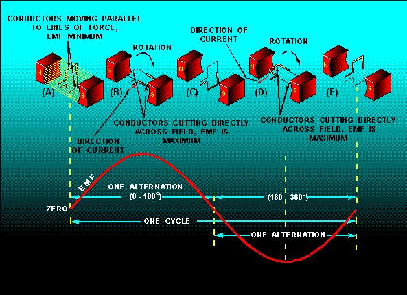
 Conductor rotates in a constant magnetic field, a sinusoidal wave is generated N B C D S A B C D A When the conductor is moving parallel with")
9 Generation of a sine wave:» Sinusoidal voltages are produced by ac generators and electronic oscillators.» 2 way to generate AC current: (a) Conductor rotates in a constant magnetic field, a sinusoidal wave is generated N B C D S A B C D A When the conductor is moving parallel with the lines of flux, no voltage is induced. Motion of conductor Conduc tor 9

10 (b) Conductor remain constant whole the magnetic field moved. - A bar magnet passes through a coil When magnet s S-pole is leaving the coil, induced I flows in such a direction as to produce a N-pole to oppose the leaving of magnet. The induced I become zero. I is about to change direction. When magnet s N-pole is moving into coil, induced I flows in such a direction as to produce a N-pole to oppose the approaching of magnet. Induced Voltage: the voltage produced within the conductor. The voltage induced in a conductor is directly proportional to the rate at which the conductor cuts the magnetic lines of forces. 10
11 The speed of conductor movement The faster the conductor moves, the greater the induced voltage coz it cut more lines of force in a given period of time, voltage increase. The strength of magnetic field Stronger magnetic field will result in more lines of force, induced voltage will higher. The length of the conductor in the field The longer the conductor, the greater the induced voltage coz longer conductor cut more line of force as it moves through the field. The angle at which the conductor cuts the field. If the conductor moves at a right angle with respect to the field, maximum amount of voltage is induced. 11
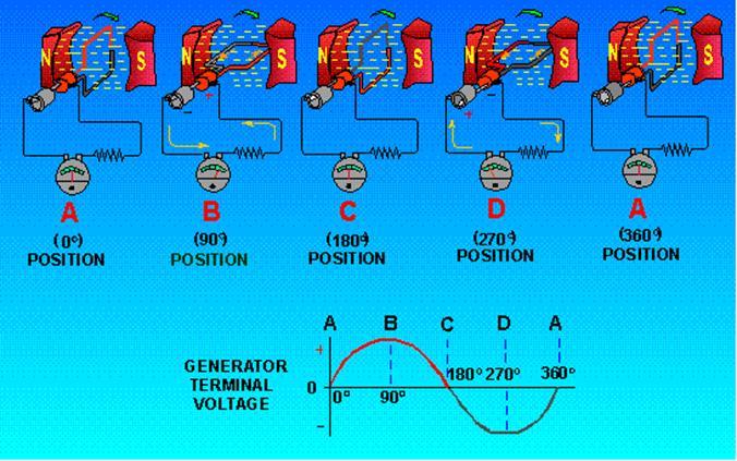
12 1.2.2 DRAW AC WAVEFORMS PRODUCED BY A SIMPLE ALTERNATING CURRENT GENERATOR ( 1 LOOP 2 POLE MAGNET )» Generators convert rotational energy to electrical energy. When a conductor is in a magnetic field and either the field or the conductor moves, an emf (voltage) is induced in the conductor. This effect is called electromagnetic induction.» A loop of wire rotating in a magnetic field produces a voltage which constantly changes in amplitude and direction.» The waveform produced is called a sine wave and is a graphical picture of alternating current (ac). One complete revolution (360 ) of the conductor produces one cycle of ac.» The cycle is composed of two alternations: a positive alternation and a negative alternation. One cycle of ac in one second is equal to 1 hertz (1 Hz). 12
13 AC GENERATOR: - The AC generator has slip rings that pick up the induces voltage through a complete relation cycle. - The induced voltage is related to the number of lines flux cut. - When the loop in moving parallel with the lines of flux, no voltage is induced. - When the loop in moving perpendicular to the lines of flux, the maximum voltage is induced. N S brushes arm ature slip rings 13
14 14
15 15
16 Basic Single Coil AC Generator 16
17 MULTI POLE AC GENERATOR: - By increasing the number of poles, the number of cycle per revolution can be increased. 17
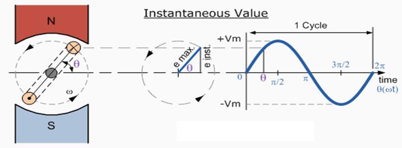
18 1.2.3 DEVELOP AN EQUATION OF A SINUSOIDAL WAVEFORM, e = Em sin ( ωt ± θ ) e = Em sin ( ωt ± θ )» Em = is the peak current. (unit: A).» ω = is the angular frequency (unit: radians per second; rads) The angular frequency is related to the physical frequency, (unit = hertz), which represents the number of cycles per second, by the equation.» t = is the time (unit: second).» θ = the phase, specifies where in its cycle the oscillation begin at t= 0. 18
19 Basic trigonometry: 19
20 Sinusoidal equation: θ 20
21 » An elementary four pole generator with a six turn rotor coil generates the following voltage wave e = 24.2 sin 36t» Determine the frequency. So; ω = 2πf f = ω/2π = 36 / 2π = Hz 21
22 1.3.1 DEFINE FREQUENCY, PERIOD, PEAK VALUE OR AMPLITUDE AND THEIR RELATIONS. FREQUENCY: - Frequency ( f ) is the number of cycles that a sine wave completes in one second. - Frequency is measured in hertz (Hz). - The more cycles completed in 1 sec, the higher the frequency. - Relationship between frequency (f) & period (T) is f = 1/T 1.0 s 22 If 3 cycles of a wave occur in one second, the frequency is 3.0 Hz
23 - The period and frequency are reciprocals of each other. 1 f T AND 1 T f - Thus, if you know one, you can easily find the other. If the period is 50 ms, the frequency is 0.02 MHz = 20 khz. 23
24 PERIOD: - The time required for a sine wave to complete 1 full cycle is called a period (T). - A cycle consists of 1 complete +ve and 1 complete ve alternation. - The period of sine wave can be measured between any 2 corresponding points on the waveform. AMPLITUDE@ PEAK VALUE (Vp/Ip): - The amplitude is the maximum value of a voltage or current. - The amplitude of a sine wave is only measured from the center to the maximum point. 20 V The amplitude (A) of this sine wave is 20 V The period is 50.0 ms 15 V 10 V 0 V A t ( ms) -10 V -15 V -20 V T 24
25 PEAK TO PEAK VALUE: - The current from the +ve and ve peak. - The peak to peak values are represented as Ipp. - Where: Vpp = Ipp = 2Ip 20 V 15 V 10 V 0 V t ( ms) -10 V -15 V -20 V V PP 25
26 1.3.2 DATERMINE THE VARIOUS VOLTAGE AND CURRENT VALUES OF A SINE WAVE a. INSTANTANEOUS VALUE AT ANY POINT: - The instantaneous values of a sine wave current are different at any different point along the curve, having +ve and ve value. - Represent as: I b. RMS VALUE: - The rms ( root mean square ) effective value of a sinusoidal voltage is equal to the dc voltage that produces the same amount of heat in a resistance as does the sinusoidal voltage. - V rms = Vp - I rms = Ip NOTE: = 1_ 2 26

27 c. AVERAGE VALUE: - By definition, the average value is as times the peak value - The average value is the total area under the half cycle curve divided by the distance in radians of the curve along the horizontal axis. - Vavg = /π Vp - Iavg = /π Ip The peak voltage of this waveform is 20 V. 20 V 15 V The rms voltage is 10 V V P V avg V rms 14.1 V. 0 V t ( ms) The average value for the sinusoidal voltage is 12.7 V. -10 V -15 V -20 V 27
28 d. FORM FACTOR: - Rms value _ = 1.11 Average value e. PEAK FACTOR: - Peak maximum value = peak value rms value 28

29 1.3.3 CALCULATE MEAN VALUE, RMS VALUE AND PEAK FACTOR FOR A GIVEN WAVEFORM: EXAMPLE: Mean/ average value = = Vp = V = 12.74V Rms value = = Vp = V Peak factor = = Vp / rms value = 20V / = = V 29
30 FORMULA UNIT Frequency 1 Hz f T Period 1 Sec T f Amplitude Ip A Peak to Peak value 2 x 2 x Ip A RMS value x x Ip A Average value x x Ip A Form Factor RMS value = 1.11 Average value Peak Factor Peak value = RMS value
31 » An alternating voltage is given by v = sin 314t v. Find; a) The r.m.s voltage b) The frequency c) The instantaneous value of voltage when t = 4ms Solution: a) Vrms = x Vp = x 282.8V = 200V b) ω = 314 rad/s = 2πf f = 314 / 2π = 50Hz Note: radians. Convert radians degree x 180 / π = a) v = sin ( 314 x 4ms ) = sin = sin = 268.9V 31
32 » An alternating voltage is given by v = 310 sin 100πt Determine; a) The amplitude b) The root mean square voltage c) The average voltage d) The instantaneous value of voltage when t = 5ms e) The time when the voltage first reach maximum value Solution: a) Amplitude = Vp = 310V b) Vrms = x Vp = x 310V = V c) Vavg = x Vp = x 310V = V d) V = 310 sin [ 100 π x 5ms ] + 30 = 310 sin [ ] = 310 sin [ ] = V e) 310 = 310 sin [100πt + 30 ] 310 / 310 = sin [100πt + 30 ] 1 = sin [100πt + 30 ] sin -1 1 = 100πt = 100πt Convert radian degree x 180 / π = 90 Convert degree radian 60 x π / 180 = rad 60 = 100πt rad = 100πt 32 so; t = rad / 100π = 3.33ms
 or radians.")
33 1.4.1 SHOW HOW TO MEASURE A SINE WAVE IN TERMS OF ANGLES» Angular measurements can be made in degrees ( o ) or radians. 33

34 1.4.1 SHOW HOW TO MEASURE A SINE WAVE IN TERMS OF ANGLES R R As angle A increases, the values of the trigonometric functions of A undergo a periodic cycle from 0, to a maximum of 1, down to a minimum of -1, and back to 0. There are several ways to express the measure of the angle A. One way is in degrees, where 360 degrees defines a complete circle. Another way to measure angles is in a unit called the radian, where 2π radians defines a complete circle. 34
35 35

36 1.4.2 DEFINE RADIAN - The Radian, (rad) is defined mathematically as a quadrant of a circle where the distance subtended on the circumference equals the radius (r) of the circle. - There are 360 o or 2p radians in one complete revolution. - Since the circumference of a circle is equal to 2π x radius, so 1 radian = 360 o /2π = 57.3 o. - Radian = the standard unit of angular measurement. 36
37 1.4.3 CONVERT RADIANS TO DEGREE - Because there are 2p radians in one complete revolution and 360 o in a revolution, the conversion between radians and degrees is easy to write. - To find the number of radians, given the number of degrees: rad 2 rad p 360 degrees - To find the number of degrees, given the radians: 360 deg 2 p rad rad 37
38 1.4.4 DETERMINE THE PHASE ANGLE OF A SINE WAVE Phase shift: - The phase of a sine wave is an angular measurement that specifies the position of a sine wave relative to a reference. - To show that a sine wave is shifted to the left or right of this reference, a term is added to the equation given previously. e Em sin t Where, θ = phase shift 38
39 Voltage (V) Example of a wave that lags the reference: Referenc e Peak voltage v = 30 V sin (wt - 45 o ) and the equation has a negative phase shift Notice that a lagging sine wave is below the axis at 0 o Angle ( ) 39
40 Voltage (V) Example of a wave that leads the reference: Referenc e Notice that a leading sine wave is above the axis at 0 o Peak voltage v = 30 V sin (wt + 45 o ) and the equation has a positive phase shift 360 Angle ( ) 40
41 1.5.1 DEFINE PHASOR - A phasor is a straight line drawn in such a way that its length is related to the amplitude of the sine wave represented, and its angular position relative to other phasors is related to the phase difference between the quantities. - Phase denotes the particular point in the cycle of a waveform, measured as an angle in degrees. 41
42 1.5.2 EXPLAIN HOW PHASORS ARE RELATED TO THE SINE WAVE FORMULA - The sine wave can be represented as the projection of a vector rotating at a constant rate. This rotating vector is called a phasor. - The phasor represented by the arrow is rotating in an anticlockwise direction about the centre origin point, describing the sine wave as it rotates. - Phasors allow AC calculations to use basic trigonometry. The sine function in trigonometry is the ratio of the opposite side of a right triangle to the adjacent side. 90 V p v = V p sin = 19.2 V V p = 25 V = V p 42
43 1.5.3 DRAW A PHASOR DIAGRAM Phasor Diagram a. At any point in time, the length of the red dotted line represents the instantaneous value of the wave. b. The length of the phasor represents the amplitude of the wave. c. The angle of the phasor gives the phase of the waveform. d. Increments in phasor angle in the circular diagram are equivalent to time or angle increments along the horizontal axis of the waveform diagram. e. So with this addition of angular information, the phasor gives a relatively simple way to show the complex relationships that exist between sine waves in an ac circuit. 43
44 » The position of a phasor at any instant can be expressed as a positive angle, measured counterclockwise from 0 or as a negative angle equal to positive angle of phasor negative angle of
45 1.5.4 DISCUSS ANGULAR VELOCITY» When a phasor rotates through 360 or 2p radians, one complete cycle (since 1 revolution = 360 )» In 1 second, phasor will rotate through f through f x 360» In calculation, it is more common to use angular unit RADIAN (rad) where 360 = 2π rads.» The phasor therefore rotate through 2π f radians per second.» The velocity of rotation is called the angular velocity (w). w = 2pf (Note that this angular velocity is expressed in radians per second.) 45
46 1.6.1 APPLY OHM S LAW TO RESISTIVE CIRCUITS WITH AC SOURCES - The voltage V across a resistor is proportional to the current I travelling through it. - This is true at all times: V = RI. ohm law 46
47 1.6.1 APPLY OHM S LAW TO RESISTIVE CIRCUITS WITH AC SOURCES - The voltage V across a resistor is proportional to the current I travelling through it. - This is true at all times: V = RI. ohm law 47
48 1.6.2 APPLY KIRCHHOFF S VOLTAGE LAW AND CURRENT LAW TO RESISTIVE CIRCUITS WITH AC SOURCES» Kirchhoff's Voltage and Current Laws apply to all AC circuits as well as DC circuits. Kirchhoff's Current Law: - The sum of current into a junction equals the sum of current out of the junction. - i 2 + i 3 = i 1 + i 4 - The sum of all currents at a node must equal to zero. 48
49 1.6.2 APPLY KIRCHHOFF S VOLTAGE LAW AND CURRENT LAW TO RESISTIVE CIRCUITS WITH AC SOURCES Kirchhoff's Voltage Law: - The algebraic sum of the voltage (potential) differences in any loop must equal zero. - Example: V1 + V2 Vs = 0 49
50 1.6.3 DETERMINE POWER IN RESISTIVE AC CIRCUITS - In a direct current circuit the power is equal to the voltage times the current, or P = E X I. - The TRUE POWER depends upon the phase angle between the current and voltage. - True power of a circuit is the power actually used in the circuit. - Measured in watts. 50
51 1.6.3 DETERMINE POWER IN RESISTIVE AC CIRCUITS - Note that the waveform for power is always positive, never negative for this resistive circuit. - This means that power is always being dissipated by the resistive load, and never returned to the source as it is with reactive loads. 51
52 Example: In this example, the current to the load would be 2 amps. The power dissipated at the load would be 240 watts. Because this load is purely resistive (no reactance), the current is in phase with the voltage, and calculations look similar to that in an equivalent DC circuit. 52

53 Calculate the current and power consumed in a single phase 240V AC circuit by a heating element which has an impedance of 60 Ohms. Also draw the corresponding phasor diagram.» The Active power consumed by the AC resistance is calculated as:» The corresponding phasor diagram is given as: 53
54 » A sinusoidal voltage supply defined as: V(t) = 100 x cos(ωt + 30 o ) is connected to a pure resistance of 50 Ohms. Determine its impedance and the value of the current flowing through the circuit. Draw the corresponding phasor diagram. Converting this voltage from the time-domain expression into the phasor-domain expression gives us: Applying Ohms Law gives us: The corresponding phasor diagram will be 54
55 1. In North America, the frequency of ac utility voltage is 60 Hz. The period is A. 8.3 ms B ms C. 60 ms D. 60 s 55
56 2. The amplitude of a sine wave is measured.. A. at the maximum point B. between the minimum and maximum points C. at the midpoint D. anywhere on the wave 56
57 3. Which property of a sine wave does the length of a phasor represent? A. Frequency B. Phase C. Amplitude D. Instantaneous value 57
58 4. In the equation v = V p sin ωt ±, the letter v stands for the A. peak value B. average value C. rms value D. instantaneous value 58
59 Voltage (V) Referenc e Peak voltage V Angle ( ) 5. Give the suitable sinusoidal equation for waveform V1 above A. V 1 = 30 sin ωt B. V 1 = 30 sin ωt + 45 C. V 1 = 30 sin ωt - 45 D. V 1 = 30 sin ωt ± 45 59
60 6. The number of radians in 90 o is A. p/2 B. p C. 2p/3 D. 2p 60
61 7. For the waveform shown, the same power would be delivered to a load with a dc voltage of A V 60 V B V 45 V 30 V C V D V 0 V t ( ms) -30 V -45 V -60 V 61
62 8. A control on the oscilloscope that is used to set the desired number of cycles of a wave on the display is A. volts per division control B. time per division control C. trigger level control D. horizontal position control 62
63 9. Convert the angle of 3π/5 radian to degree unit. A. 180 B. 118 C. 108 D
64 10. Alternating current changes in.. A. Direction only B. Value only C. Both value and direction D. Frequency and value but not direction 64
65 1. B 2. A 3. C 4. D 5. C 6. A 7. C 8. B 9. C 10. C 65
Circuit Analysis-II. Circuit Analysis-II Lecture # 2 Wednesday 28 th Mar, 18
 Circuit Analysis-II Angular Measurement Angular Measurement of a Sine Wave ü As we already know that a sinusoidal voltage can be produced by an ac generator. ü As the windings on the rotor of the ac generator
THE SINUSOIDAL WAVEFORM
 Chapter 11 THE SINUSOIDAL WAVEFORM The sinusoidal waveform or sine wave is the fundamental type of alternating current (ac) and alternating voltage. It is also referred to as a sinusoidal wave or, simply,
Ac fundamentals and AC CIRCUITS. Q1. Explain and derive an expression for generation of AC quantity.
 Ac fundamentals and AC CIRCUITS Q1. Explain and derive an expression for generation of AC quantity. According to Faradays law of electromagnetic induction when a conductor is moving within a magnetic field,
Alternating current circuits- Series RLC circuits
 FISI30 Física Universitaria II Professor J.. ersosimo hapter 8 Alternating current circuits- Series circuits 8- Introduction A loop rotated in a magnetic field produces a sinusoidal voltage and current.
ELECTROMAGNETIC INDUCTION AND ALTERNATING CURRENT (Assignment)
") ELECTROMAGNETIC INDUCTION AND ALTERNATING CURRENT (Assignment) 1. In an A.C. circuit A ; the current leads the voltage by 30 0 and in circuit B, the current lags behind the voltage by 30 0. What is the
ELECTROMAGNETIC INDUCTION AND ALTERNATING CURRENT (Assignment) 1. In an A.C. circuit A ; the current leads the voltage by 30 0 and in circuit B, the current lags behind the voltage by 30 0. What is the
Chapter 33. Alternating Current Circuits
 Chapter 33 Alternating Current Circuits Alternating Current Circuits Electrical appliances in the house use alternating current (AC) circuits. If an AC source applies an alternating voltage to a series
Alternating voltages and currents
 Alternating voltages and currents Introduction - Electricity is produced by generators at power stations and then distributed by a vast network of transmission lines (called the National Grid system) to
Chapter 6: Alternating Current. An alternating current is an current that reverses its direction at regular intervals.
 Chapter 6: Alternating Current An alternating current is an current that reverses its direction at regular intervals. Overview Alternating Current Phasor Diagram Sinusoidal Waveform A.C. Through a Resistor
CHAPTER 5 CONCEPTS OF ALTERNATING CURRENT
 CHAPTER 5 CONCEPTS OF ALTERNATING CURRENT INTRODUCTION Thus far this text has dealt with direct current (DC); that is, current that does not change direction. However, a coil rotating in a magnetic field
Electrical Theory. Power Principles and Phase Angle. PJM State & Member Training Dept. PJM /22/2018
 Electrical Theory Power Principles and Phase Angle PJM State & Member Training Dept. PJM 2018 Objectives At the end of this presentation the learner will be able to: Identify the characteristics of Sine
Phasor. Phasor Diagram of a Sinusoidal Waveform
 Phasor A phasor is a vector that has an arrow head at one end which signifies partly the maximum value of the vector quantity ( V or I ) and partly the end of the vector that rotates. Generally, vectors
Chapter 11. Alternating Current
 Unit-2 ECE131 BEEE Chapter 11 Alternating Current Objectives After completing this chapter, you will be able to: Describe how an AC voltage is produced with an AC generator (alternator) Define alternation,
QUESTION BANK ETE (17331) CM/IF. Chapter1: DC Circuits
 CM/IF. Chapter1: DC Circuits") QUESTION BANK ETE (17331) CM/IF Chapter1: DC Circuits Q1. State & explain Ohms law. Also explain concept of series & parallel circuit with the help of diagram. 3M Q2. Find the value of resistor in fig.
QUESTION BANK ETE (17331) CM/IF Chapter1: DC Circuits Q1. State & explain Ohms law. Also explain concept of series & parallel circuit with the help of diagram. 3M Q2. Find the value of resistor in fig.
AC Theory, Circuits, Generators & Motors
 PDH-Pro.com AC Theory, Circuits, Generators & Motors Course Number: EE-02-306 PDH: 6 Approved for: AK, AL, AR, GA, IA, IL, IN, KS, KY, MD, ME, MI, MN, MO, MS, MT, NC, ND, NE, NH, NJ, NM, NV, OH, OK, OR,
Chapter 6: Alternating Current
 hapter 6: Alternating urrent 6. Alternating urrent.o 6.. Define alternating current (A) An alternating current (A) is the electrical current which varies periodically with time in direction and magnitude.
CHAPTER 9. Sinusoidal Steady-State Analysis
 CHAPTER 9 Sinusoidal Steady-State Analysis 9.1 The Sinusoidal Source A sinusoidal voltage source (independent or dependent) produces a voltage that varies sinusoidally with time. A sinusoidal current source
Look over Chapter 31 sections 1-4, 6, 8, 9, 10, 11 Examples 1-8. Look over Chapter 21 sections Examples PHYS 2212 PHYS 1112
 PHYS 2212 Look over Chapter 31 sections 1-4, 6, 8, 9, 10, 11 Examples 1-8 PHYS 1112 Look over Chapter 21 sections 11-14 Examples 16-18 Good Things To Know 1) How AC generators work. 2) How to find the
PHYSICS WORKSHEET CLASS : XII. Topic: Alternating current
 PHYSICS WORKSHEET CLASS : XII Topic: Alternating current 1. What is mean by root mean square value of alternating current? 2. Distinguish between the terms effective value and peak value of an alternating
Chapter 33. Alternating Current Circuits
 Chapter 33 Alternating Current Circuits C HAP T E O UTLI N E 33 1 AC Sources 33 2 esistors in an AC Circuit 33 3 Inductors in an AC Circuit 33 4 Capacitors in an AC Circuit 33 5 The L Series Circuit 33
5.0 THREE PHASE SYSTEM
 5.0 THREE PHASE SYSTEM ET 201 BAKISS HIYANA BAU BAKAR JKE, POLISAS 1 COURSE LEARNING OUTCOME 1. Explain AC circuit concept and their analysis using AC circuit law. 2. Apply the knowledge of AC circuit
2.0 AC CIRCUITS 2.1 AC VOLTAGE AND CURRENT CALCULATIONS. ECE 4501 Power Systems Laboratory Manual Rev OBJECTIVE
 2.0 AC CIRCUITS 2.1 AC VOLTAGE AND CURRENT CALCULATIONS 2.1.1 OBJECTIVE To study sinusoidal voltages and currents in order to understand frequency, period, effective value, instantaneous power and average
Goals. Introduction. To understand the use of root mean square (rms) voltages and currents.
 voltages and currents.") Lab 10. AC Circuits Goals To show that AC voltages cannot generally be added without accounting for their phase relationships. That is, one must account for how they vary in time with respect to one another.
Lab 10. AC Circuits Goals To show that AC voltages cannot generally be added without accounting for their phase relationships. That is, one must account for how they vary in time with respect to one another.
Alternating Current. Slide 1 / 69. Slide 2 / 69. Slide 3 / 69. Topics to be covered. Sources of Alternating EMF. Sources of alternating EMF
 Slide 1 / 69 lternating urrent Sources of alternating EMF Transformers ircuits and Impedance Topics to be covered Slide 2 / 69 LR Series ircuits Resonance in ircuit Oscillations Sources of lternating EMF
Alternating Current. Slide 2 / 69. Slide 1 / 69. Slide 3 / 69. Slide 4 / 69. Slide 6 / 69. Slide 5 / 69. Topics to be covered
 Slide 1 / 69 lternating urrent Sources of alternating EMF ircuits and Impedance Slide 2 / 69 Topics to be covered LR Series ircuits Resonance in ircuit Oscillations Slide 3 / 69 Sources of lternating EMF
AC Circuits. Nikola Tesla
 AC Circuits Nikola Tesla 1856-1943 Mar 26, 2012 Alternating Current Circuits Electrical appliances in the house use alternating current (AC) circuits. If an AC source applies an alternating voltage of
AC Fundamental. Simple Loop Generator: Whenever a conductor moves in a magnetic field, an emf is induced in it.
 AC Fundamental Simple Loop Generator: Whenever a conductor moves in a magnetic field, an emf is induced in it. Fig.: Simple Loop Generator The amount of EMF induced into a coil cutting the magnetic lines
An induced emf is the negative of a changing magnetic field. Similarly, a self-induced emf would be found by
 This is a study guide for Exam 4. You are expected to understand and be able to answer mathematical questions on the following topics. Chapter 32 Self-Induction and Induction While a battery creates an
Electrical Engineering Fundamentals
 Electrical Engineering Fundamentals EE-238 Sheet 1 Series Circuits 1- For the circuits shown below, the total resistance is specified. Find the unknown resistance and the current for each circuit. 12.6
Exercise 9: inductor-resistor-capacitor (LRC) circuits
 circuits") Exercise 9: inductor-resistor-capacitor (LRC) circuits Purpose: to study the relationship of the phase and resonance on capacitor and inductor reactance in a circuit driven by an AC signal. Introduction
Exercise 9: inductor-resistor-capacitor (LRC) circuits Purpose: to study the relationship of the phase and resonance on capacitor and inductor reactance in a circuit driven by an AC signal. Introduction
1. If the flux associated with a coil varies at the rate of 1 weber/min,the induced emf is
 1. f the flux associated with a coil varies at the rate of 1 weber/min,the induced emf is 1 1. 1V 2. V 60 3. 60V 4. Zero 2. Lenz s law is the consequence of the law of conservation of 1. Charge 2. Mass
ECE 2006 University of Minnesota Duluth Lab 11. AC Circuits
 1. Objective AC Circuits In this lab, the student will study sinusoidal voltages and currents in order to understand frequency, period, effective value, instantaneous power and average power. Also, the
Table of Contents. Introduction...2 Conductors and Insulators...3 Current, Voltage, and Resistance...6
 Table of Contents Introduction...2 Conductors and Insulators...3 Current, Voltage, and Resistance...6 Ohm s Law... 11 DC Circuits... 13 Magnetism...20 Alternating Current...23 Inductance and Capacitance...30
15. the power factor of an a.c circuit is.5 what will be the phase difference between voltage and current in this
 1 1. In a series LCR circuit the voltage across inductor, a capacitor and a resistor are 30 V, 30 V and 60 V respectively. What is the phase difference between applied voltage and current in the circuit?
Electromagnetic Oscillations and Currents. March 23, 2014 Chapter 30 1
 Electromagnetic Oscillations and Currents March 23, 2014 Chapter 30 1 Driven LC Circuit! The voltage V can be thought of as the projection of the vertical axis of the phasor V m representing the time-varying
Alternating Current Study Guide. Preface. This module is DIFFICULT.
 Preface This module is DIFFICULT. This material will take more effort to understand and more effort to pass than tests from previous modules. This is on par with a college-level electrical engineering
Electromagnetic Induction - A
 Electromagnetic Induction - A APPARATUS 1. Two 225-turn coils 2. Table Galvanometer 3. Rheostat 4. Iron and aluminum rods 5. Large circular loop mounted on board 6. AC ammeter 7. Variac 8. Search coil
CHAPTER 2. Basic Concepts, Three-Phase Review, and Per Unit
 CHAPTER 2 Basic Concepts, Three-Phase Review, and Per Unit 1 AC power versus DC power DC system: - Power delivered to the load does not fluctuate. - If the transmission line is long power is lost in the
PHYS 1442 Section 004 Lecture #15
 PHYS 1442 Section 004 Lecture #15 Monday March 17, 2014 Dr. Andrew Brandt Chapter 21 Generator Transformer Inductance 3/17/2014 1 PHYS 1442-004, Dr. Andrew Brandt Announcements HW8 on Ch 21-22 will be
CHAPTER 6: ALTERNATING CURRENT
 CHAPTER 6: ALTERNATING CURRENT PSPM II 2005/2006 NO. 12(C) 12. (c) An ac generator with rms voltage 240 V is connected to a RC circuit. The rms current in the circuit is 1.5 A and leads the voltage by
AC generator theory. Resources and methods for learning about these subjects (list a few here, in preparation for your research):
:") AC generator theory This worksheet and all related files are licensed under the Creative Commons Attribution License, version 1.0. To view a copy of this license, visit http://creativecommons.org/licenses/by/1.0/,
AC generator theory This worksheet and all related files are licensed under the Creative Commons Attribution License, version 1.0. To view a copy of this license, visit http://creativecommons.org/licenses/by/1.0/,
Alternating Current Page 1 30
 Alternating Current 26201 11 Page 1 30 Calculate the peak and effective voltage of current values for AC Calculate the phase relationship between two AC waveforms Describe the voltage and current phase
EE42: Running Checklist of Electronics Terms Dick White
 EE42: Running Checklist of Electronics Terms 14.02.05 Dick White Terms are listed roughly in order of their introduction. Most definitions can be found in your text. Terms2 TERM Charge, current, voltage,
CHAPTER 14 ALTERNATING VOLTAGES AND CURRENTS
 CHAPTER 4 ALTERNATING VOLTAGES AND CURRENTS Exercise 77, Page 28. Determine the periodic time for the following frequencies: (a) 2.5 Hz (b) 00 Hz (c) 40 khz (a) Periodic time, T = = 0.4 s f 2.5 (b) Periodic
Sample Question Paper
 Scheme G Sample Question Paper Course Name : Electrical Engineering Group Course Code : EE/EP Semester : Third Subject Title : Electrical Circuit and Network 17323 Marks : 100 Time: 3 hrs Instructions:
ET1210: Module 5 Inductance and Resonance
 Part 1 Inductors Theory: When current flows through a coil of wire, a magnetic field is created around the wire. This electromagnetic field accompanies any moving electric charge and is proportional to
Chapt ha e pt r e r 11 Inductors
 Chapter 11 Inductors The Basic Inductor When a length of wire is formed onto a coil, it becomes a basic inductor Magnetic lines of force around each loop in the winding of the coil effectively add to the
UNIT-04 ELECTROMAGNETIC INDUCTION & ALTERNATING CURRNT
 UNIT-04 ELECTROMAGNETIC INDUCTION & ALTERNATING CURRNT.MARK QUESTIONS:. What is the magnitude of the induced current in the circular loop-a B C D of radius r, if the straight wire PQ carries a steady current
Chapter 24. Alternating Current Circuits
 Chapter 24 Alternating Current Circuits Objective of Lecture Generators and Motors Inductance RL Circuits (resistance and inductance) Transformers AC REMINDER: WORK ON THE EXAMPLES Read physics in perspective
AC Sources and Phasors
 AC Sources and Phasors Circuits powered by a sinusoidal emf are called AC circuits, where AC stands for alternating current. Steady-current circuits are called DC circuits, for direct current. The instantaneous
AP Physics C. Alternating Current. Chapter Problems. Sources of Alternating EMF
 AP Physics C Alternating Current Chapter Problems Sources of Alternating EMF 1. A 10 cm diameter loop of wire is oriented perpendicular to a 2.5 T magnetic field. What is the magnetic flux through the
Chapter 30 Inductance, Electromagnetic. Copyright 2009 Pearson Education, Inc.
 Chapter 30 Inductance, Electromagnetic Oscillations, and AC Circuits 30-7 AC Circuits with AC Source Resistors, capacitors, and inductors have different phase relationships between current and voltage
PHYS 1444 Section 003 Lecture #19
 PHYS 1444 Section 003 Lecture #19 Monday, Nov. 14, 2005 Electric Generators DC Generator Eddy Currents Transformer Mutual Inductance Today s homework is homework #10, due noon, next Tuesday!! 1 Announcements
CH 1. Large coil. Small coil. red. Function generator GND CH 2. black GND
 Experiment 6 Electromagnetic Induction "Concepts without factual content are empty; sense data without concepts are blind... The understanding cannot see. The senses cannot think. By their union only can
Sinusoids and Phasors (Chapter 9 - Lecture #1) Dr. Shahrel A. Suandi Room 2.20, PPKEE
 Dr. Shahrel A. Suandi Room 2.20, PPKEE") Sinusoids and Phasors (Chapter 9 - Lecture #1) Dr. Shahrel A. Suandi Room 2.20, PPKEE Email:shahrel@eng.usm.my 1 Outline of Chapter 9 Introduction Sinusoids Phasors Phasor Relationships for Circuit Elements
Sinusoids and Phasors (Chapter 9 - Lecture #1) Dr. Shahrel A. Suandi Room 2.20, PPKEE Email:shahrel@eng.usm.my 1 Outline of Chapter 9 Introduction Sinusoids Phasors Phasor Relationships for Circuit Elements
MAHARASHTRA STATE BOARD OF TECHNICAL EDUCATION
 Important Instructions to examiners: 1. The answers should be examined by key words and not as word-to-word as given in the model answer scheme. 2. The model answer and the answer written by candidate
KINGS COLLEGE OF ENGINEERING DEPARTMENT OF ELECTRICAL AND ELECTRONICS ENGINEERING QUESTION BANK UNIT I BASIC CIRCUITS ANALYSIS PART A (2-MARKS)
") KINGS COLLEGE OF ENGINEERING DEPARTMENT OF ELECTRICAL AND ELECTRONICS ENGINEERING QUESTION BANK YEAR / SEM : I / II SUBJECT CODE & NAME : EE 1151 CIRCUIT THEORY UNIT I BASIC CIRCUITS ANALYSIS PART A (2-MARKS)
KINGS COLLEGE OF ENGINEERING DEPARTMENT OF ELECTRICAL AND ELECTRONICS ENGINEERING QUESTION BANK YEAR / SEM : I / II SUBJECT CODE & NAME : EE 1151 CIRCUIT THEORY UNIT I BASIC CIRCUITS ANALYSIS PART A (2-MARKS)
Chapter 31 Alternating Current
 Chapter 31 Alternating Current In this chapter we will learn how resistors, inductors, and capacitors behave in circuits with sinusoidally vary voltages and currents. We will define the relationship between
CHAPTER 5 Test B Lsn 5-6 to 5-8 TEST REVIEW
 IB PHYSICS Name: Period: Date: DEVIL PHYSICS BADDEST CLASS ON CAMPUS CHAPTER 5 Test B Lsn 5-6 to 5-8 TEST REVIEW 1. This question is about electric circuits. (a) (b) Define (i) (ii) electromotive force
Experiment 9: AC circuits
 Experiment 9: AC circuits Nate Saffold nas2173@columbia.edu Office Hour: Mondays, 5:30PM-6:30PM @ Pupin 1216 INTRO TO EXPERIMENTAL PHYS-LAB 1493/1494/2699 Introduction Last week (RC circuit): This week:
Chapter 21. Alternating Current Circuits and Electromagnetic Waves
 Chapter 21 Alternating Current Circuits and Electromagnetic Waves AC Circuit An AC circuit consists of a combination of circuit elements and an AC generator or source The output of an AC generator is sinusoidal
Chapter Moving Charges and Magnetism
 100 Chapter Moving Charges and Magnetism 1. The power factor of an AC circuit having resistance (R) and inductance (L) connected in series and an angular velocity ω is [2013] 2. [2002] zero RvB vbl/r vbl
11. AC-resistances of capacitor and inductors: Reactances.
 11. AC-resistances of capacitor and inductors: Reactances. Purpose: To study the behavior of the AC voltage signals across elements in a simple series connection of a resistor with an inductor and with
Electrical Theory 2 Lessons for Fall Semester:
 Electrical Theory 2 Lessons for Fall Semester: Lesson 1 Magnetism Lesson 2 Introduction to AC Theory Lesson 3 Lesson 4 Capacitance and Capacitive Reactance Lesson 5 Impedance and AC Circuits Lesson 6 AC
PART B. t (sec) Figure 1
 Figure 1") Code No: R16128 R16 SET 1 I B. Tech II Semester Regular Examinations, April/May 217 ELECTRICAL CIRCUIT ANALYSIS I (Electrical and Electronics Engineering) Time: 3 hours Max. Marks: 7 Note: 1. Question
Code No: R16128 R16 SET 1 I B. Tech II Semester Regular Examinations, April/May 217 ELECTRICAL CIRCUIT ANALYSIS I (Electrical and Electronics Engineering) Time: 3 hours Max. Marks: 7 Note: 1. Question
ALTERNATING CURRENT. Lesson-1. Alternating Current and Voltage
 esson- ATENATING UENT Alternating urrent and oltage An alternating current or voltage is that variation of current or voltage respectively whose magnitude and direction vary periodically and continuously
PESIT Bangalore South Campus Hosur road, 1km before Electronic City, Bengaluru -100 Department of Electronics & Communication Engineering
 CONTINUOUS INTERNAL EVALUATION TEST -1 Date : 27/2/2018 Marks:60 Subject & Code : Basic Electrical Engineering, 17ELE25 Section: A,B,C,D,E Time : 8:30 am 11:30 a.m Name of faculty: Mrs. Dhanashree Bhate,
Electrical Circuits (2)
") Electrical Circuits (2) Lecture 1 Intro. & Review Dr.Eng. Basem ElHalawany Course Info Title Electric Circuits (2) Lecturer: Lecturer Webpage: Teaching Assistant (TA) Course Webpage References Software
Electrical Circuits (2) Lecture 1 Intro. & Review Dr.Eng. Basem ElHalawany Course Info Title Electric Circuits (2) Lecturer: Lecturer Webpage: Teaching Assistant (TA) Course Webpage References Software
END-OF-SUBCOURSE EXAMINATION
 END-OF-SUBCOURSE EXAMINATION Circle the letter of the correct answer to each question. When you have answered all of the questions, use a Number 2 pencil to transfer your answers to the TSC Form 59. 1.
ENGINEERING COUNCIL CERTIFICATE LEVEL ENGINEERING SCIENCE C103 TUTORIAL 18 ALTERNATING CURRENT
 ENGINEERING OUNIL ERTIFIATE LEVEL ENGINEERING SIENE 03 TUTORIAL 8 ALTERNATING URRENT On completion of this tutorial you should be able to do the following. Explain alternating current. Explain Root Mean
13. Magnetically Coupled Circuits
 13. Magnetically Coupled Circuits The change in the current flowing through an inductor induces (creates) a voltage in the conductor itself (self-inductance) and in any nearby conductors (mutual inductance)
ESO 210 Introduction to Electrical Engineering
 ESO 210 Introduction to Electrical Engineering Lecture-12 Three Phase AC Circuits Three Phase AC Supply 2 3 In general, three-phase systems are preferred over single-phase systems for the transmission
Intermediate Physics PHYS102
 Intermediate Physics PHYS102 Dr Richard H. Cyburt Assistant Professor of Physics My office: 402c in the Science Building My phone: (304) 384-6006 My email: rcyburt@concord.edu My webpage: www.concord.edu/rcyburt
APPLICATION NOTE - 018
 APPLICATION NOTE - 018 Power Transformers Background Power Transformers are used within an AC power distribution systems to increase or decrease the operating voltage to achieve the optimum transmission
Physics for Scientists & Engineers 2 2 = 1 LC. Review ( ) Review (2) Review (3) e! Rt. cos "t + # ( ) q = q max. Spring Semester 2005 Lecture 30 U E
 Review (2) Review (3) e! Rt. cos t + # ( ) q = q max. Spring Semester 2005 Lecture 30 U E") Review hysics for Scientists & Engineers Spring Semester 005 Lecture 30! If we have a single loop RLC circuit, the charge in the circuit as a function of time is given by! Where q = q max e! Rt L cos "t
Review hysics for Scientists & Engineers Spring Semester 005 Lecture 30! If we have a single loop RLC circuit, the charge in the circuit as a function of time is given by! Where q = q max e! Rt L cos "t
1. A battery has an emf of 12.9 volts and supplies a current of 3.5 A. What is the resistance of the circuit?
 1. A battery has an emf of 12.9 volts and supplies a current of 3.5 A. What is the resistance of the circuit? (a) 3.5 Ω (b) 16.4 Ω (c) 3.69 Ω (d) 45.15 Ω 2. Sign convention used for potential is: (a) Rise
Hours / 100 Marks Seat No.
 17323 14115 3 Hours / 100 Seat No. Instructions (1) All Questions are Compulsory. (2) Illustrate your answers with neat sketches wherever necessary. (3) Figures to the right indicate full marks. (4) Assume
DC and AC Circuits. Objective. Theory. 1. Direct Current (DC) R-C Circuit
 R-C Circuit") [International Campus Lab] Objective Determine the behavior of resistors, capacitors, and inductors in DC and AC circuits. Theory ----------------------------- Reference -------------------------- Young
[International Campus Lab] Objective Determine the behavior of resistors, capacitors, and inductors in DC and AC circuits. Theory ----------------------------- Reference -------------------------- Young
Aligarh College of Engineering & Technology (College Code: 109) Affiliated to UPTU, Approved by AICTE Electrical Engg.
 Affiliated to UPTU, Approved by AICTE Electrical Engg.") Aligarh College of Engineering & Technology (College Code: 19) Electrical Engg. (EE-11/21) Unit-I DC Network Theory 1. Distinguish the following terms: (a) Active and passive elements (b) Linearity and
Aligarh College of Engineering & Technology (College Code: 19) Electrical Engg. (EE-11/21) Unit-I DC Network Theory 1. Distinguish the following terms: (a) Active and passive elements (b) Linearity and
EXPERIMENT 4: RC, RL and RD CIRCUITs
 EXPERIMENT 4: RC, RL and RD CIRCUITs Equipment List An assortment of resistor, one each of (330, 1k,1.5k, 10k,100k,1000k) Function Generator Oscilloscope 0.F Ceramic Capacitor 100H Inductor LED and 1N4001
Chapter 28 Alternating Current Circuits
 History teaches us that the searching spirit of man required thousands of years for the discovery of the fundamental principles of the sciences, on which the superstructure was then raised in a comparatively
Physics 132 Quiz # 23
 Name (please (please print) print) Physics 132 Quiz # 23 I. I. The The current in in an an ac ac circuit is is represented by by a phasor.the value of of the the current at at some time time t t is is
Electrical Engineering / Electromagnetics
 Electrical Engineering / Electromagnetics. Plot voltage versus time and current versus time for the circuit with the following substitutions: A. esistor B. Capacitor C. Inductor t = 0 A/B/C A. I t t B.
Worksheet for Exploration 31.1: Amplitude, Frequency and Phase Shift
 Worksheet for Exploration 31.1: Amplitude, Frequency and Phase Shift We characterize the voltage (or current) in AC circuits in terms of the amplitude, frequency (period) and phase. The sinusoidal voltage
JEFFERSON COLLEGE COURSE SYLLABUS ETC104 AC CIRCUITS. 5 Credit Hours. Prepared by: Ronald S. Krive. Revised Date: October 2007 by Dennis Eimer
 JEFFERSON COLLEGE COURSE SYLLABUS ETC104 AC CIRCUITS 5 Credit Hours Prepared by: Ronald S. Krive Revised Date: October 2007 by Dennis Eimer Division of Technology Dr. John Keck, Dean Ms. Brenda Russell,
Module 1. Introduction. Version 2 EE IIT, Kharagpur
 Module 1 Introduction Lesson 1 Introducing the Course on Basic Electrical Contents 1 Introducing the course (Lesson-1) 4 Introduction... 4 Module-1 Introduction... 4 Module-2 D.C. circuits.. 4 Module-3
AC Theory and Electronics
 AC Theory and Electronics An Alternating Current (AC) or Voltage is one whose amplitude is not constant, but varies with time about some mean position (value). Some examples of AC variation are shown below:
Basics of Electricity
 Basics of Electricity A quickstep Online Course Siemens industry, Inc. www.usa.siemens.com/step Trademarks Siemens is a trademark of Siemens AG. Product names mentioned may be trademarks or registered
Magnetism and Induction
 Magnetism and Induction Before the Lab Read the following sections of Giancoli to prepare for this lab: 27-2: Electric Currents Produce Magnetism 28-6: Biot-Savart Law EXAMPLE 28-10: Current Loop 29-1:
AC Circuit Analysis. The Sine Wave CHAPTER 3. This chapter discusses basic concepts in the analysis of AC circuits.
 CHAPTER 3 AC Circuit Analysis This chapter discusses basic concepts in the analysis of AC circuits. The Sine Wave AC circuit analysis usually begins with the mathematical expression for a sine wave: v(t)
Trade of Electrician. Introduction to AC
 Trade of Electrician Standards Based Apprenticeship Introduction to AC Phase 2 Module No. 2.1 Unit No. 2.1.9 COURSE NOTES Created by Gerry Ryan - Galway TC Revision 1. April 2000 by Gerry Ryan - Galway
Introduction. Upon completion of Basics of Electricity you will be able to: Explain the difference between conductors and insulators
 Table of Contents Introduction...2 Electron Theory...4 Conductors, Insulators and Semiconductors...5 Electric Charges...7 Current...9 Voltage... 11 Resistance... 13 Simple Electric Circuit... 15 Ohm s
CHAPTER 6 ALTERNATING CURRENT
 HDR102 PHYSICS FOR RADIOGRAPHERS 1 CHAPTER 6 ALTERNATING CURRENT PREPARED BY: MR KAMARUL AMIN BIN ABDULLAH SCHOOL OF MEDICAL IMAGING FACULTY OF HEALTH SCIENCES LEARNING OUTCOMES At the end of the lesson,
SECTION 3 BASIC AUTOMATIC CONTROLS UNIT 12 BASIC ELECTRICITY AND MAGNETISM. Unit Objectives. Unit Objectives 2/29/2012
 SECTION 3 BASIC AUTOMATIC CONTROLS UNIT 12 BASIC ELECTRICITY AND MAGNETISM Unit Objectives Describe the structure of an atom. Identify atoms with a positive charge and atoms with a negative charge. Explain
AC CURRENTS, VOLTAGES, FILTERS, and RESONANCE
 July 22, 2008 AC Currents, Voltages, Filters, Resonance 1 Name Date Partners AC CURRENTS, VOLTAGES, FILTERS, and RESONANCE V(volts) t(s) OBJECTIVES To understand the meanings of amplitude, frequency, phase,
Contents. Core information about Unit
 1 Contents Core information about Unit UEENEEH114A - Troubleshoot resonance circuits......3 UEENEEG102A Solve problems in low voltage AC circuits...5 TextBook...7 Topics and material Week 1...9 2 Core
Direct Current Waveforms
 Cornerstone Electronics Technology and Robotics I Week 20 DC and AC Administration: o Prayer o Turn in quiz Direct Current (dc): o Direct current moves in only one direction in a circuit. o Though dc must
Part 9: Basic AC Theory
 Part 9: Basic AC Theory 9.1 Advantages Of AC Systes Dealing with alternating current (AC) supplies is on the whole ore coplicated than dealing with DC current, However there are certain advantages of AC
Downloaded from / 1
 PURWANCHAL UNIVERSITY II SEMESTER FINAL EXAMINATION-2008 LEVEL : B. E. (Computer/Electronics & Comm.) SUBJECT: BEG123EL, Electrical Engineering-I Full Marks: 80 TIME: 03:00 hrs Pass marks: 32 Candidates
PHYSICS - CLUTCH CH 29: ALTERNATING CURRENT.
 !! www.clutchprep.com CONCEPT: ALTERNATING VOLTAGES AND CURRENTS BEFORE, we only considered DIRECT CURRENTS, currents that only move in - NOW we consider ALTERNATING CURRENTS, currents that move in Alternating